ARCHITECTURAL PORTFOLIO
C H A R M I G A J J A R


 Library, University of Idaho


Idaho Museum of International Diaspora Digital Fabrication Design Build 15 19 25 Corgan: Aviation San Antonio International Airport TABLE OF CONTENT A Landing Space Green House Affordable Twin-House Project 11 Moscow Affordable Housing Trust Living Design 1 High Knit 7 Moscow- Pullman Regional Airport Airlift 29 MGMA: Industrail Dabney Industrial Warehouse Professional Work
High Knit
Mixed-Use Commerical Tower
Charlotte- North Carolina
Fall 2021
Academic work: Individual Project COTE Top Ten for Students Competition
Certification: LEED Silver
Softwares used: Revit, Enscape, AutoCAD, Energy Plus, Photoshop, Illustrator, Indesign
“A design for recovery of lost resources”
High Knit is a mixed use commercial tower located in uptown Charllotte, surrounded by the city’s prominent educational institutions including LEED certified UNC Center City building. The tower opens an opportunity to collobrate with the neighboring educational insititutions to develop a 198,120 gross sq.ft building with 150,000 sq ft of commerical space
The design is developed considering the intangible site elements. The deconstructive structure communicates the history of natural and manmade disasters through innovative smart facades.

2080

Design based on Climate Change 2020


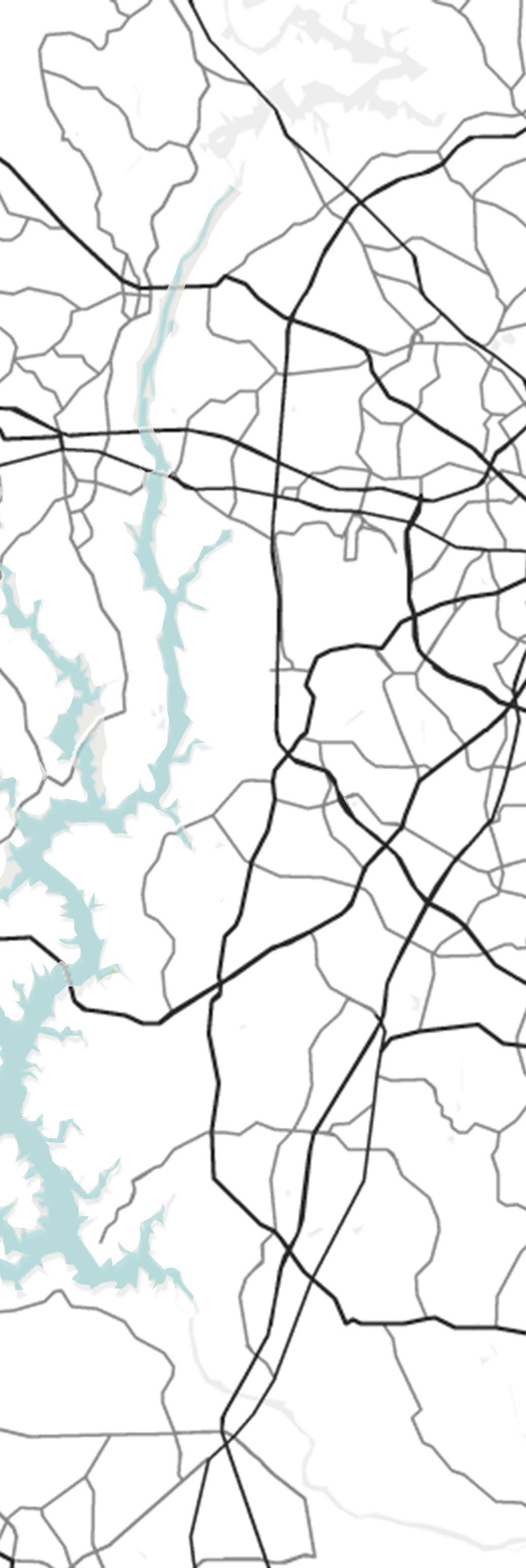
Connecting Tangible & Intangible context

 Dan River Coal-ash Spill 2014
Circulation LYNX Light
Hurricane Hugo 1989
Vehicular
Rail Track
Temperature
Temperature
1

1

Diagrid

Operable Windows

Rain-water collected through hollow wooden facade
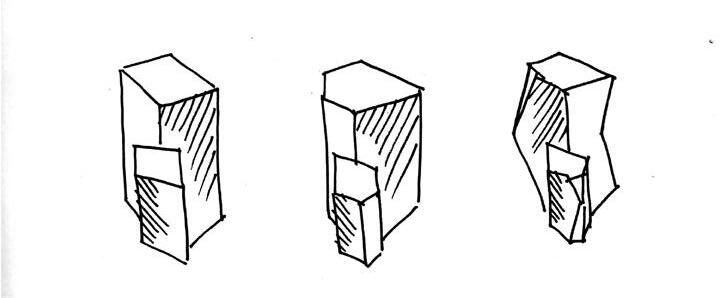
Form Development based on wind pattern
Design for Integration
Rain- water collected through hollow wooden facade

Design for Equitable Community
Farmer’s Market Pavilion Urban Boardwalk with Mural
Design for Water
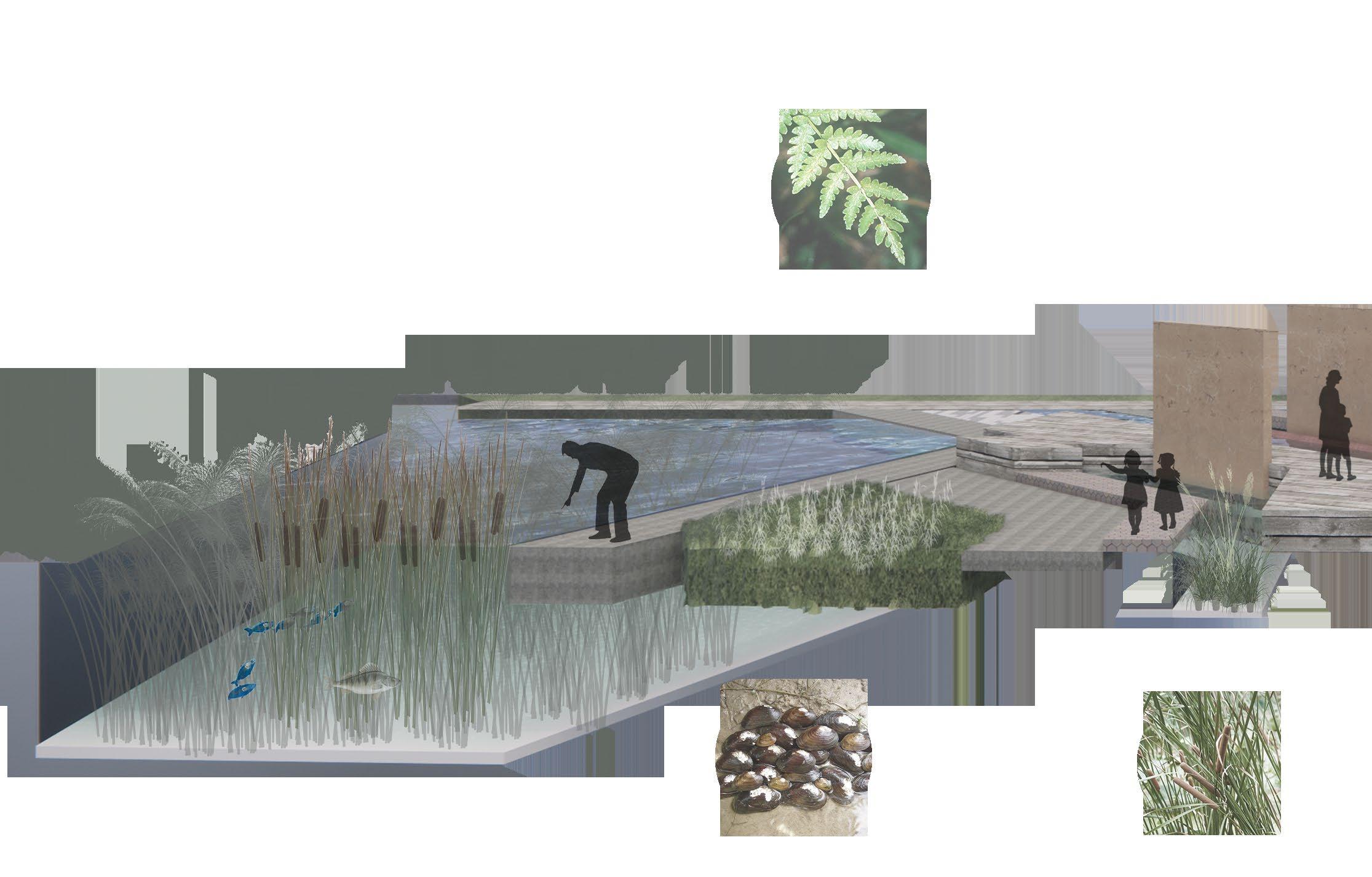
Grey-water treatment through constructed wetlands. Stored rain water in cisterns


 Wooden Facade
3

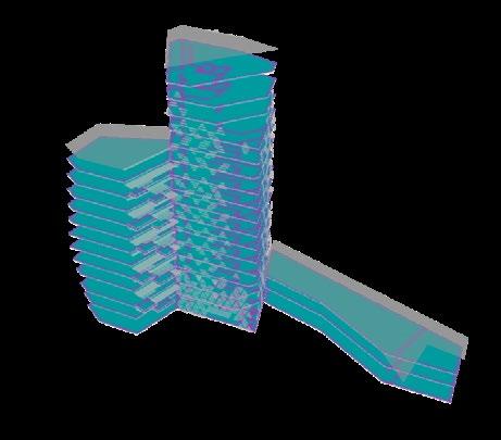
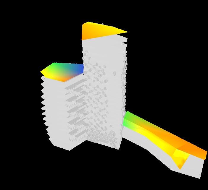
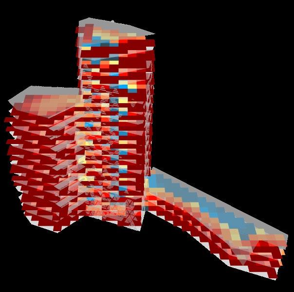


Design for Energy
Energy generated through Solar PV panels on horizontal louvers

Design for Resources
Recycled Coal Ash Pavers
Timber Clay Mural Wall

Design for Economy
Less labour cost for Mass Timber construction
Use of renewable energy resources
Spatial Daylight 71% COVID Safe 90% 1700 Occupany Sun Hours 12 hrs a day
5
Cattail, Narrow
Virginia Chainfern Herb
James spinymussel
 Constructed Wetland: Revit & Enscape leaved
Recycled coal-ash Permeable Pavers
Cutgrass, Rice
Button
Bush
Airlift
Moscow-Pullman Regional Airport
Idaho Concrete Masonry Association: Finalist Fall 2020
Academic work: Individual Project
Idaho Concrete Masonry Association Competition
Certification: Finalist
Softwares used: Revit, Enscape, AutoCAD, Photoshop, Illustrator, Indesign
“Every travel experience is influenced by some kind of expectations. Reaching out and achieving those expectations satisfy the purpose of travel. This volumetric space encourages a new spirit to push the limits of travel.”
The Idaho concrete masonry Association provided the third-year architectural students of the University of Idaho with an opportunity to design a regional Moscow-Pullman airport using concrete masonry units as the main material. The design challenges the acoustic characteristics of a masonry unit, by creating a soft curvilinear surface that directs the circulation movement inside the building. Incorporating the sky as a limit, the design allows the space to receive natural daylighting with the help of a massive overhang window situated on the East facade, while at the same time welcoming the new visitors with a spectacular view of Moscow Mountain.


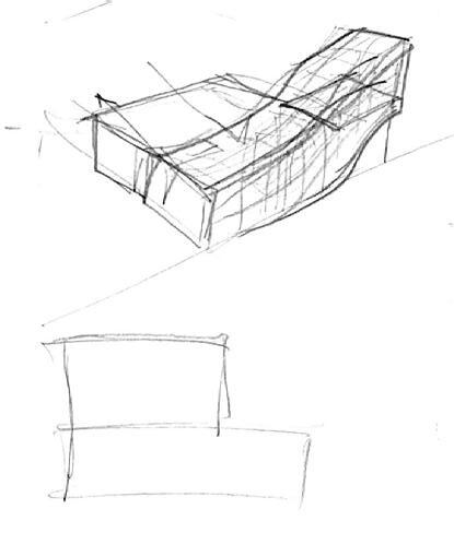
Volumetric sketches analyzing the circulation movement
7


 Sunlight through facade pattern
Concrete Roof
Private Public Inbound Baggage Outbound Baggage Departure Arrival Public Circulation Baggage Circulation Space Distribution 9
Concrete Waffle Slab

A Landing Space
Idaho Museum of International Diaspora Boise- Idaho
Fall 2020
Academic work: Group Project
Contribution: Site Analysis, Exterior Shading design, Exterior perspectives and Renders, Building Sections, Wall Section, Building Structure detail, 3D model
Softwares used: Revit, Enscape, AutoCAD, Photoshop, Illustrator
“As a landing place, the IMID provides belonging to all displaced people of the world. It contributes to the built, cultural, and economic vitality of the Boise community. The impression of the IMID story endures in the hearts and memories of all who visit”
The Idaho Museum of International Diaspora (IMID) displays a wide culture and history of the diverse communities settled in Boise, allowing every individual to celebrate and explore a variety of immersive global, cultural, and intellectual experiences right here in Idaho.
Inspired by the World Center for Birds of Prey, known for protecting extinct species and giving them a new home. The Idaho Museum of International Diaspora acts as a home for all wanderers of the world and their stories. Its form, representative of a nest symbolizes hope within. Along with the universal inclusive design, the building aligns with IMID’s goals to provide safety and well-being.

Values


Attraction Sustainability Well being Inclusive
11

Entrance Plaza: Revit & Enscape
The green exterior ramp seamlessly continues the circulation inside the building taking a form of a central spiral core. This way of movement is sensitive to all age groups and capabilities, ensuring an equal experience for everyone. The exposed douglas fir gridshell structure covered with zinc roof cladding provides protection against extreme Boise weather, while at the same time creating a comforting warmth throughout the building.

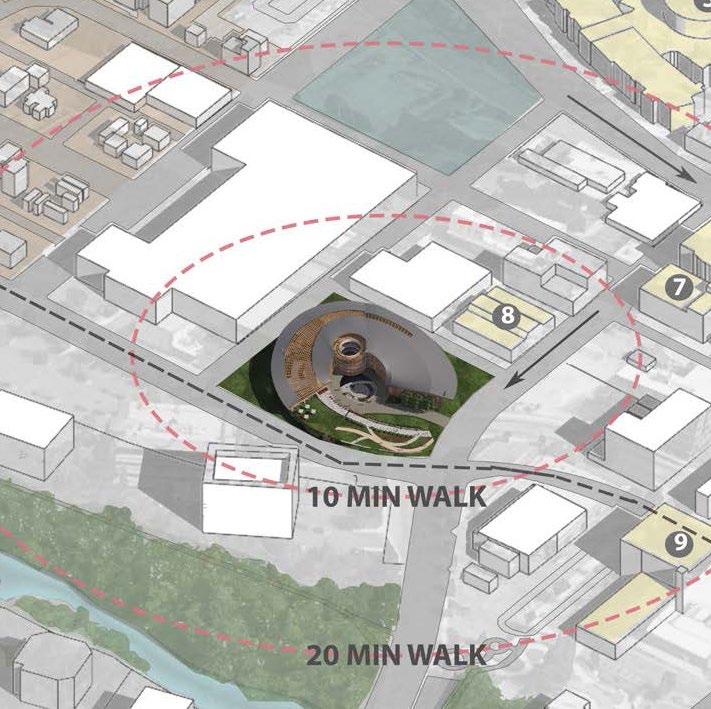

Site Plan


13
Weatherproof Zinc Roofing
Theater (LVL-2)
Library (LVL-1)
Theater(LVL-1)

Level
Program Exhibit Space Administration Office Theater Level
Program
Douglas Fir Gridshell Structure
3
2
South Eastern Asian Diaspora Exhibit Admin Office Library (LVL-2)
Program Gallery
Level 1
Gift Shop Court De Foodies
Isometric:
Exploded
Enscape & Photoshop
Green House
Digital Fabrication Studio
Blacksburg- Virginia Spring 2022
Academic work: Group Project
Softwares used: Revit, Lumion, Rhino, Grasshopper, AutoCAD, Photoshop, Illustrator, Indesign
Contribution: Design of the Wood fabric Door
“An innovative barn design with high-tech facility”
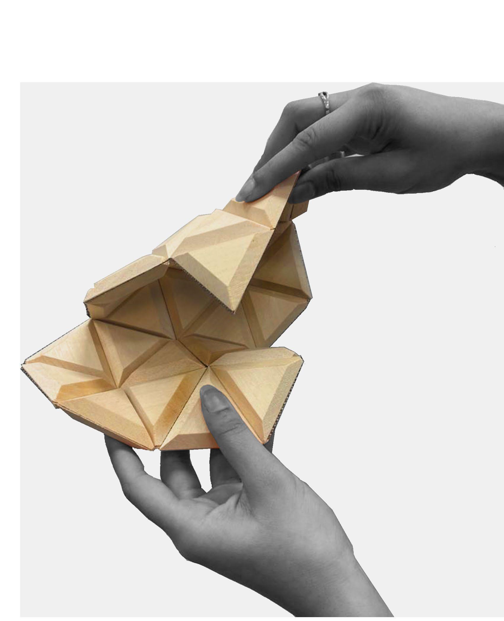
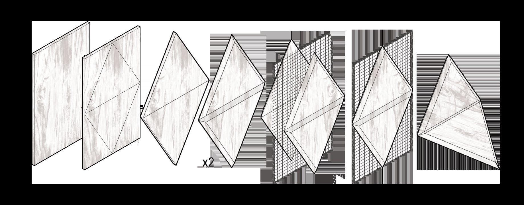
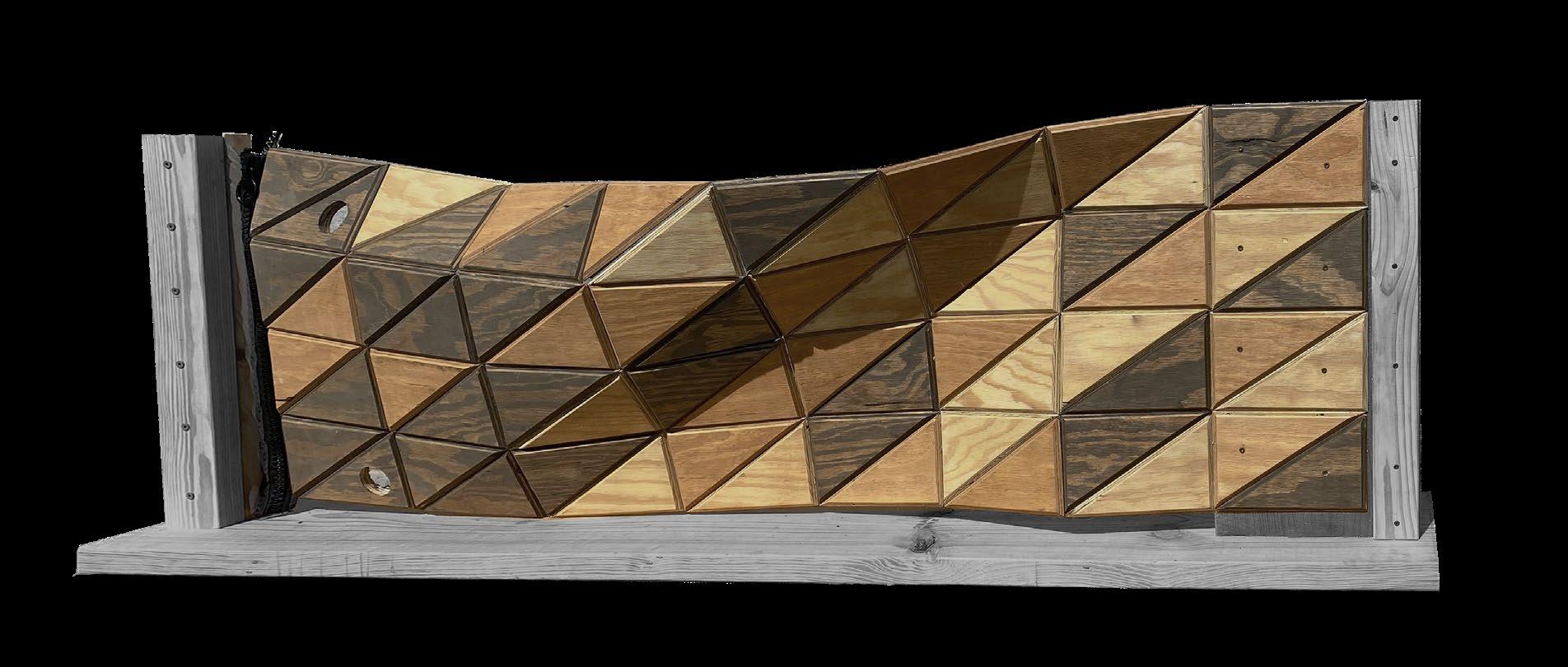
Digital Fabrication Studio at Virginia Tech provided a great platform to explore innovative strategies using smart materials to analyze a design problem. The wood Fabric Door is a newly experimented skin with a mesh sandwiched between the Chamfered Edged wood pieces that allow the layer to bend in multiple direction


15
Wood Triangular cut 45 deg Bevel cuts Insert Mesh Sandwich Mesh Final Bent Product



17

Prototype Model Wooden Frame Wood Fabric Mesh Wood Fabric Metal Hooks Wooden Frame 4” 1” 8” 41/2” Column Timber Frame Waterproofing Screen Mesh Metal Hook Wooden Handle Zipper Wood Fabric Screen Mesh
Mosow Affordable Housing Trust
Affordable Twin-House Project
Spring 2021
Academic work: Design Build
Group Role: Group Leader
Contribution: East Unit of the house, Site Analysis, Interior Perspectives, Floor plan design straegy, Overall contribution in formation of the structure, 3D model
Softwares used: Revit, Enscape, AutoCAD, Photoshop, Illustrator
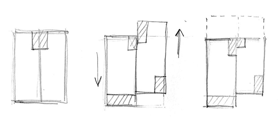
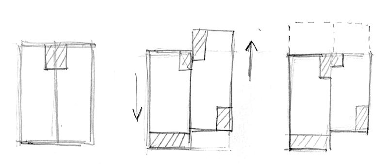
The Moscow Affordable Housing Trust is a twinhouse unit located in Moscow, Idaho. The project challenged us to satisfy the needs of the client to include having one ADA accessible bedroom & bathroom on the first floor, along with a community gathering space. Our team of final year undergraduate students were successful in providing spacious bedroom on the first floor with barrier-free circulation between the kitchen, dining, living, and personal deck area for the client. The shared entrance allowed for community interaction.

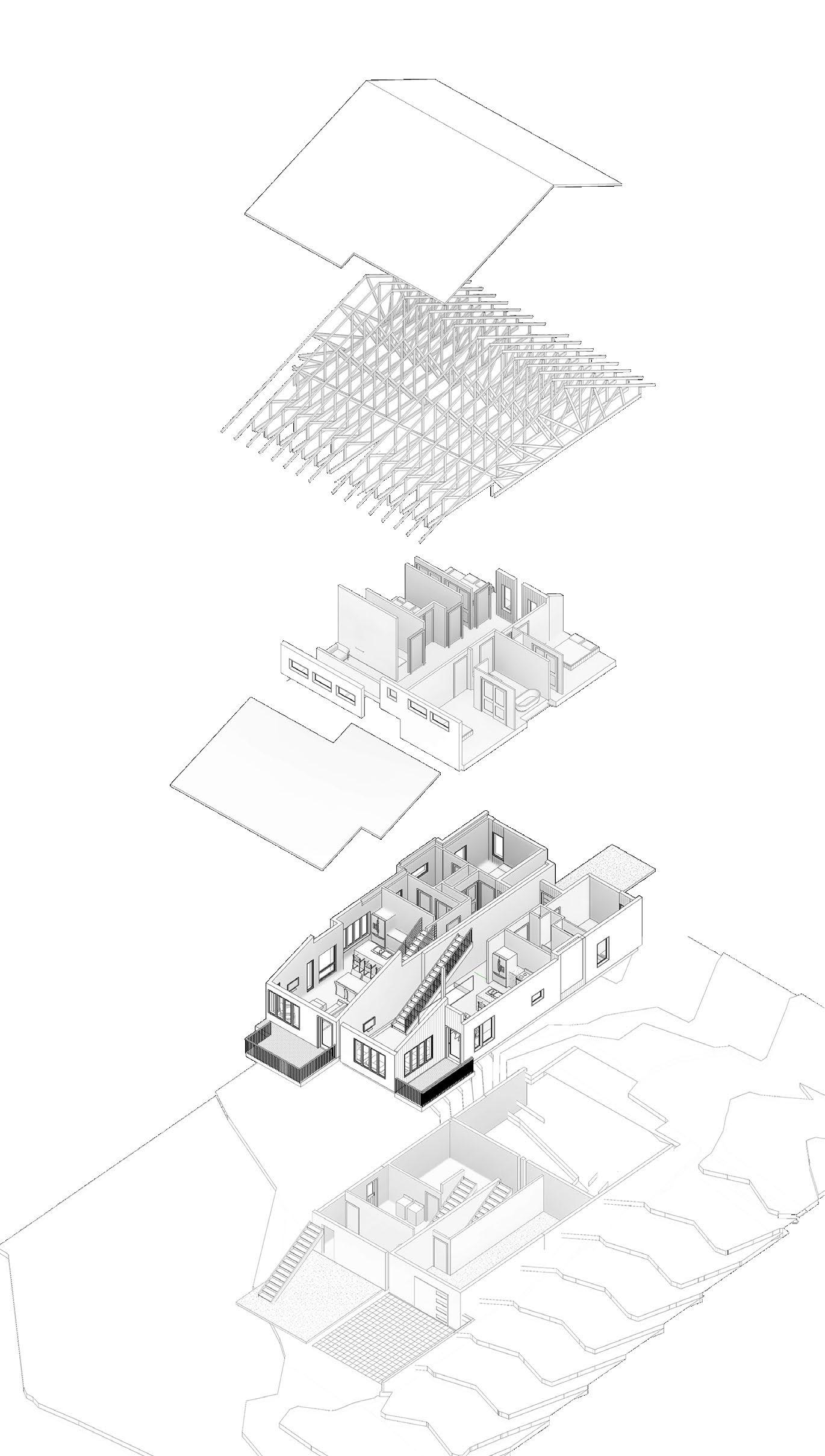
Basement
First Floor
Second Floor
19
Truss Roof

21 BEDROOM 128 SF 64 SF ENTRY 69 SF BATH 77 SF DINING ROOM LIVING ROOM 162 SF 101 120 SF DECK 6'-0" 10'-10" DOWN UP LIVING ROOM 138 SF DINING ROOM 100 SF BEDROOM 117 SF 11'-0" 4'-2" 102 109 DECK 77 SF 13'-0" 6'-7" DW DW 44'-6" 1 A118 1 A119 3 A134 105 106 104 103 107 115 108 JULIET BALCONY W/D 66 SF BATH A120 KITCHEN 127 SF BUILT IN SEATING DOWN UP 139 SF KITCHEN CHASE INSULATED 2X4 CLOSET 5'-10" 1'-4" A2 A2 A2 A2 A2 A2 A2 A2 A2 A1 A1 A3 A3 A3 A3 A3 A3 A3 A3 A3 A3 A3 A5 A5 A5 A4 A4 A5 A5 A5 A5 E5 E6 E8 E7 N5 N8 W6 W7 W8 E4 W9 S7 S8 W11 W10 1 A125 A132 1 2 A134 1 17' 17' A B C D E F G 1 2 3 4 11'-5" 9'-5" 10'-7" 8'-7" 8'-2" 3'-1" 6" 3' 2'-10" 1'-8" 5'-6" 1'-8" 1'-2" 9' 8'-3" 3' 4' 4'-6" 4'-9" 3' 7'-3" 5' 4'-8" 12'-4" 6'-2" 3' 13'-3" 3'-9" 6'-2" 5'-5" 8'-2" 3 1 4 2 3 1 4 5' 11'-7" 7'-3" 2'-1" 2'-6" 11'-11" 11'-8" 11'-11" 7'-8" 14'-6" 11' 3'-4" 2' 12' 10'-8" 5 6 5 3' A1 1' 2 A121 3 A121 1 A120 1 A122 1 A121 112 110 3'-0" 111 First Floor
Plan: Revit
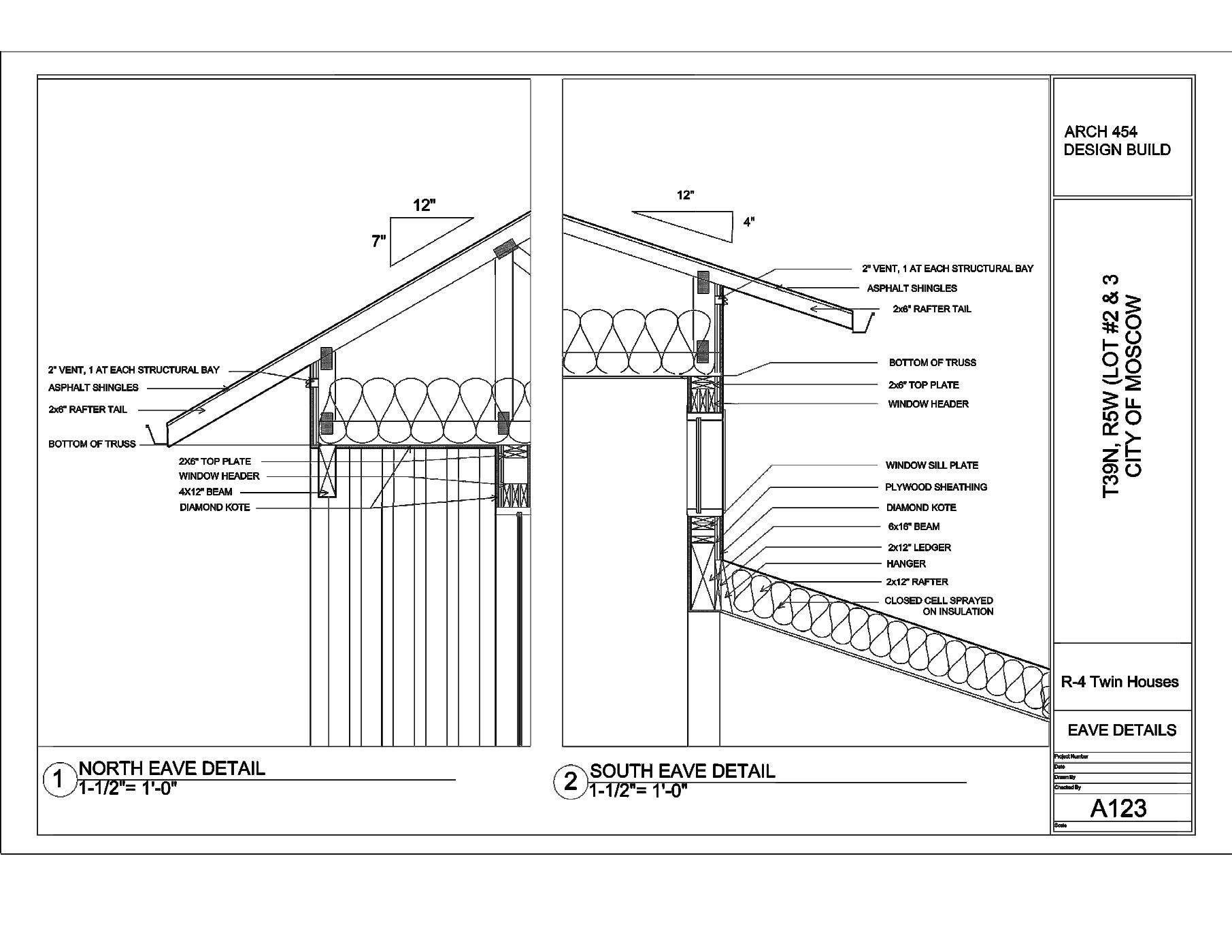
ARCH 454 DESIGN BUILD

FLASHING
SIDING TRIM ANCHOR BOLT FINISHED FLR. 1/2" P.W. FLASHING
HANGER WOOD TRUSS JOINT 3/4" P.W. 1/2" GYP. TRIM
Wall Section Detail: Revit
2X6”
2” VENT AT STRUCTURAL
ASPHALT SHINGLES Scale Date Drawn By Checked By Project Number 1/2" = 1'-0" 04/19/2021 EAST WALL SECTION T39N, R5W (LOT #2 & 3 CITY OF MOSCOW R-4 Twin Houses Checker Gregory 04/19/2021 Project Number A121 Basement -8' - 11 1/4" A126 2" X 6" KICKERS
N.T.S
BOTTOM OF TRUSS
RAFTER TRAIL
BAY
3 EAST WALL SECTION DETAIL 3" = 1' 0" 3 A121
#5 G60 @ 23" O,C. or per Table 404.1.2 (8) R-30
2X6” TOP PLATE WINDOW HEADER 4X12” BEAM DIAMOND KOTE


23
Level 1 0' - 0" Level 1 0' - 0" Level 2 10' - 0" Level 2 10' - 0" Basement -9' - 0" Basement -9' - 0" Bottom of Truss 18' - 0" Bottom of Truss 18' - 0" 3 Ridge Level 28' - 1 3/4" Ridge Level 28' - 1 3/4" LOBBYLOBBY LOBBYLOBBY CRAWL SPACE 2' 0" CRAWL SPACE 2' -0" SEPERATION FIREWALL SECTION 1 2"=1'-0" 1 A122 24" FRT PLY WOOD EACH SIDE SEPERATION FIREWALL SECTION DETAIL AT FOUNDATION 3"=1'-0" 4 5/8" TYPE X GYPSUM R-21 FIBERGLASS BATT INSULATION FILL CAVITY 3/4" AIR GAP TRIM WOOD FLOOR FINISH 3 4" PW HANGER ANCHOR BOLT CRAWL SPACE CRAWL SPACE 5/8" TYPE X GYPSUM R-21 FIBERGLASS BATT INSULATION FILL CAVITY 3/4" AIR GAP TRIM HANGER WOOD FLOOR FINISH 3 4" PW SEPERATION FIREWALL SECTION DETAIL AT FIRST LEVEL 3"=1'-0" 3 2" STEEL CHANNEL @BASE 2" FIRE-SHIELD SHAFTLINER 2" FIRE-SHIELD SHAFTLINER Date Drawn By Checked By Project Number WALL SECTION DETAIL CITY OF MOSCOW R-4 Twin Houses Checker Anjan 04/19/2021 Project Number A122 ARCH 454 DESIGN BUILD 415, 421 POWERS AVE
San Antonio International Airport
Corgan Associates Inc.
Summer 2023- Present
Professional work: Aviation
Project Architect: Andy Bell
Project Manager: Landon Moore
Contribution: 30 % Schematic Design Package, Life Safety Plans, Baggage Handling Studies, Vertical Circulation, Aircraft Layouts, Daylighting Analysis
Softwares used: Revit, Enscape, Bluebeam, Photoshop
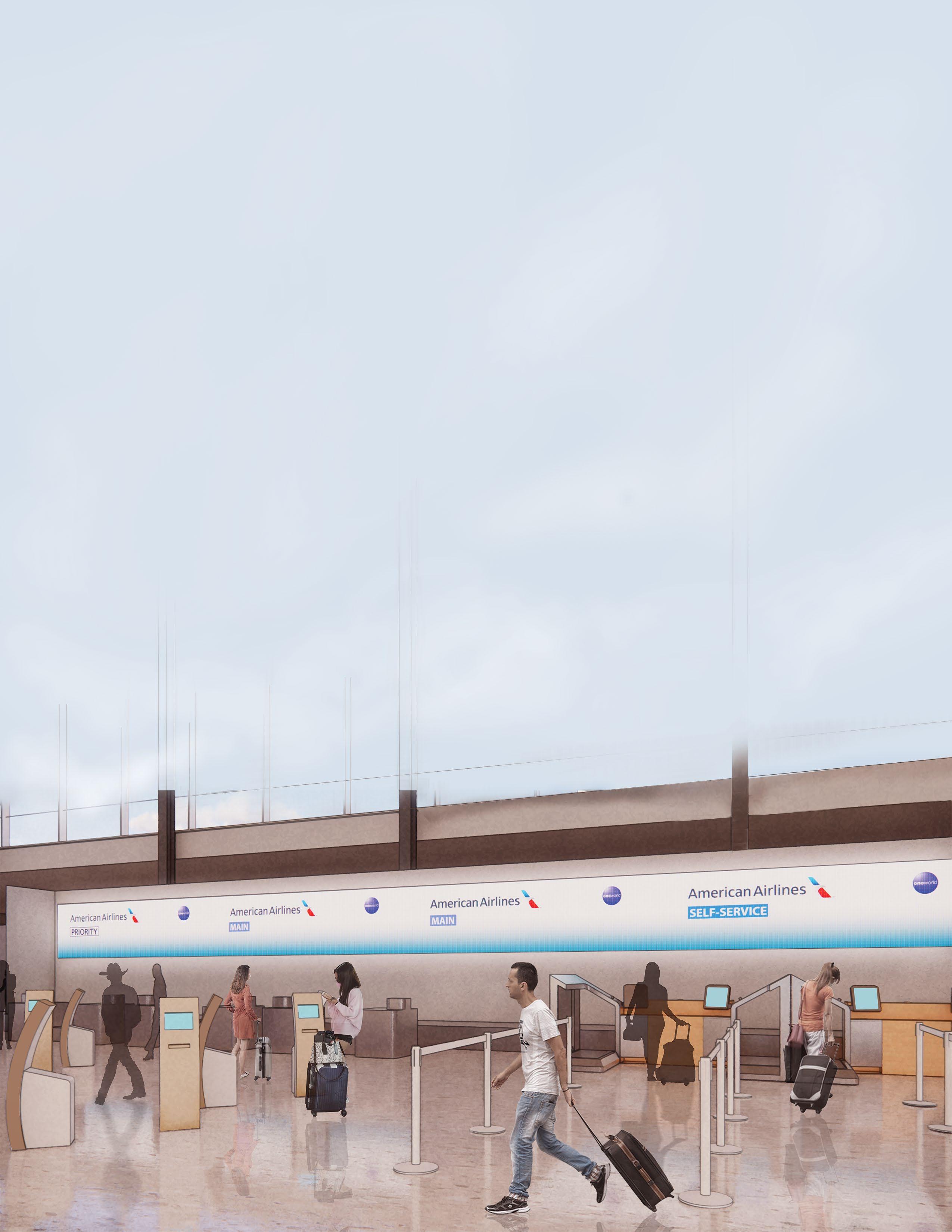
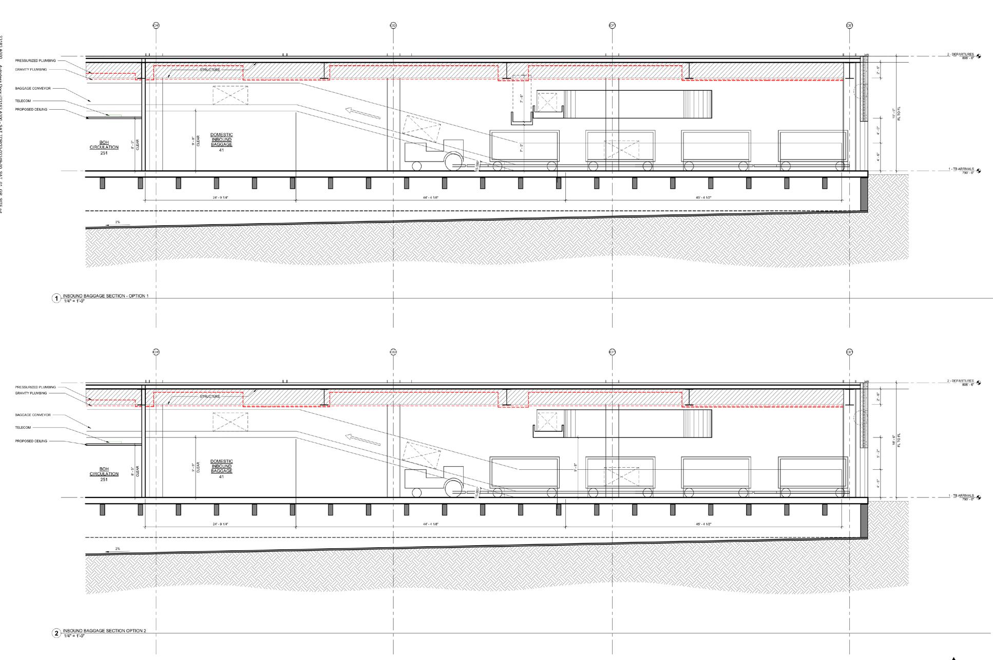
Located at the heart of a vibrant city, the San Antonio International Airport aims to overcome the rising growth of passenger demand through the construction of Terminal C. My contribution to the project began with multiple explorations of daylighting analysis for the ticketing area to provide glare reduction in highly active zone. Over the early schematic design phase, I created multiple study exhibits to understand the baggage handling systems, gatehouse programming, aircraft parking layouts, vertical circulation and hold room seating arrangements. With the progression of the project to a 30% Schematic Design set, I was accountable for generating life safety plans and understanding the occupant load for the terminal.


Daylighting Analyis Climate Studio
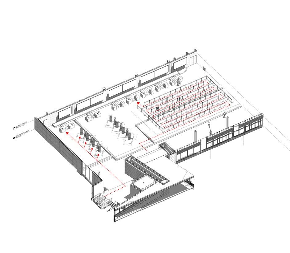
Ticketing Area 25

Baggage Handling Systems: Inbound
Baggage Handling Systems: Outbound
27


Gatehouse Study
Dabney Industrial Warehouse
Morgan Gick McBeath & Associates
Summer 2022
Professional work: Industrial
Project Architect: William McBeath
Project Manager: Anam Akhter
Contribution: Schematic Design Package, Promotional Design Set, Revit Model, Weekly Meetings
Softwares used: Revit, Enscape

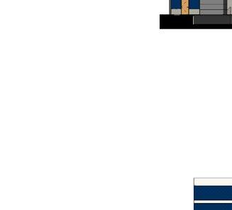
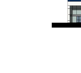

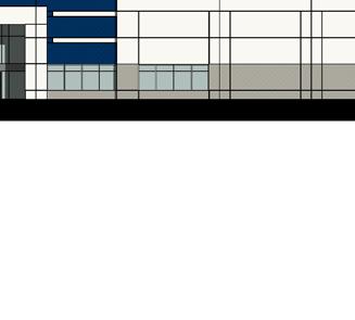
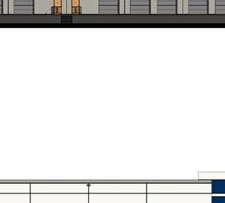


A E D C B 60' 0" 50' 0" 50' 0" 50' 0" 20' 0" 25' 0" 25' 0" 20' 0" 20' 0" 25' 0" 25' 0" 2' 6" 22' 6" 25' 0" A E D C B 25' 0" 25' 0" 20' 0" 20' 0" 20' 0" 25' 0" 25' 0" 22' 6" 2' 6" 25' 0" Level 1 0" 1 11 2 3 4 5 6 7 8 9 10 29 TO. PANEL 42' -0" 52' 0" 52' 0" 52' 0" 52' 0" 52' 0" 52' 0" 52' 0" 52' 0" 52' 0" 52' 0" Level 1 0" 1 11 2 3 4 5 6 7 8 9 10 52' 0" 52' 0" 52' 0" 52' 0" 104' 0" 52' 0" 52' 0" 52' - 0" 52' 0" 26' 0" 26' 0" 29 TO. PANEL 42' -0" 23' 6" 2' 6" 26' 0" 26' 0" 26' 0" 26' 0" 26' 0" 26' 0" 26' 0" 26' 0" 26' 0" 26' 0" 26' 0" 26' 0" 26' 0" 26' 0" 26' 0" 23' 6" 2' 6" 26' 0" 1/16" = 1'-0" 4 SOUTH ELEVATION Site
Front Elevation
Plan


 Library, University of Idaho


 Dan River Coal-ash Spill 2014


 Wooden Facade


 Constructed Wetland: Revit & Enscape leaved
Recycled coal-ash Permeable Pavers
Cutgrass, Rice
Button
Bush


 Sunlight through facade pattern
Concrete Roof


