Chapter 7.5
Canterbury-Bankstown Development Control Plan 2023
June 2023 (Amended May 2025)
Draft for exhibition
May 2025


Canterbury-Bankstown Development Control Plan 2023
June 2023 (Amended May 2025)
Draft for exhibition
May 2025
The City of Canterbury-Bankstown acknowledges the traditional custodians of the land, water and skies of Canterbury-Bankstown, the Darug (Darag, Dharug, Daruk, Dharuk) People.
We recognise and respect their cultural heritage, beliefs and relationship with the land. We acknowledge that they are continuing importance to Aboriginal and Torres Strait Islander peoples living today.
Council also acknowledges other Aboriginal and Torres Strait Islander language groups in the City and works closely with Aboriginal and Torres Strait Islander communities to advance reconciliation in the City.

We’re committed to creating a liveable and loveable City for all our residents


Great Cities
We believe in creating vibrant, dynamic, and diverse communities that offer opportunities for people to connect, pursue their passions, and contribute to the world around them.
We protect and prioritise nature in and around our city to enhance environmental sustainability and improve the quality of life for our residents.
Design Excellence
People First
We encourage buildings, spaces, and objects that are both beautiful and practical, enhancing the beauty, accessibility, and safety of our built environment. We prioritise the needs, preferences, and aspirations of our community in all aspects of urban planning and design, creating supportive and enriching places people love.
Community
We engage with our community to ensure their needs and aspirations are reflected in the outcome, creating sustainable, resilient, vibrant, diverse, and inclusive places.
Sustainability
We seek designs that reduce negative impacts on the environment while also promoting social and economic well-being.
Naturally Green Net-Zero
We encourage our community to design buildings and places that produce as much renewable energy as they consume, reducing greenhouse gas emissions, lowering energy bills, and increasing resilience to environmental shocks and stresses.
Canterbury Local Centre, along with other significant centres in the Canterbury-Bankstown Local Government Area, have an area specific Development Control Plan (DCP). This DCP contains the following parts:
Introduction Understanding Place Designing the Public Domain Building Layout, Form and Design
General Provisions Key Sites Definitions
This Chapter of the Canterbury-Bankstown DCP 2023, (CBDCP 2023), supports the Canterbury-Bankstown Local Environmental Plan 2023 (LEP), by providing additional objectives, principles and development controls to enhance the function, design and amenity of development within the Canterbury Local Centre, (also referred to as ‘the Local Centre’ in this Chapter).
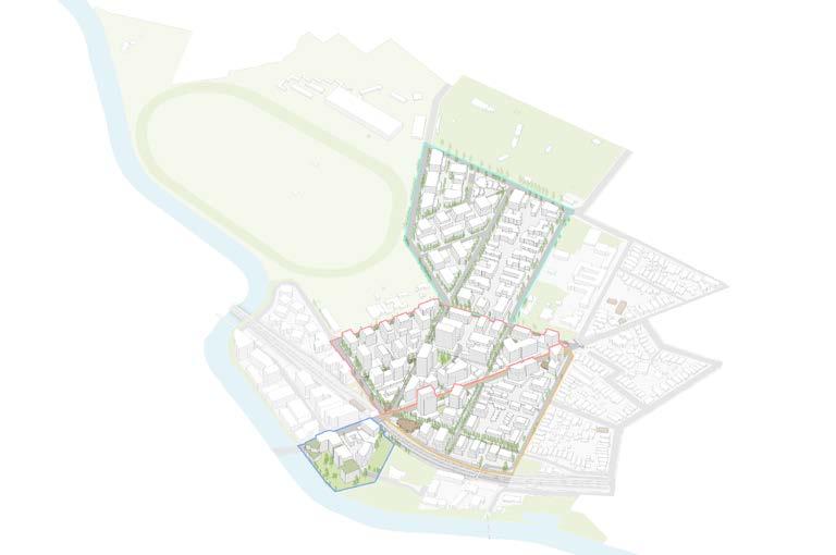
This Chapter of the CBDCP 2023 applies to all development on the land within the Canterbury Local Centre as identified in Figure 1. Other Chapters of the CBDCP 2023 must be addressed as part of Development Applications lodged for development in the Local Centre. Where there is an inconsistency between the controls in this Chapter and other Chapters in the CBDCP 2023 in relation to development in the Local Centre, this chapter prevails to the extent of the inconsistency.
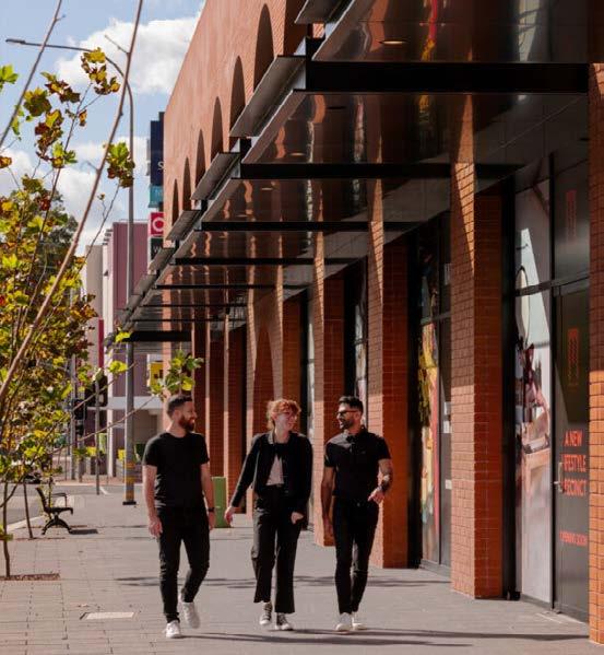
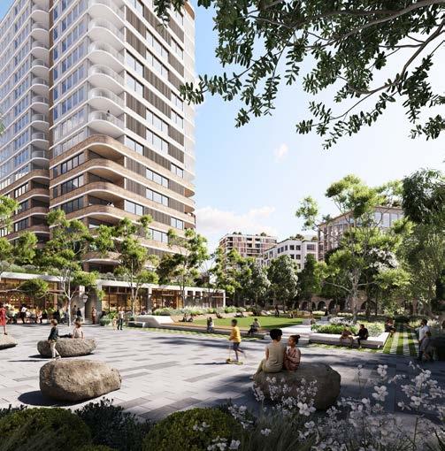
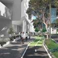
The Local Centre will celebrate its heritage, connection to the Cooks River, and green leafy character to create a lively and distinctive destination. A new civic street along with Canterbury Square will form the key feature of the precinct supported by improved cycle and pedestrian connections, access to sunlight and shade,and thoughtfully designed buildings. With excellent access to public transport and open space, the Local centre will be a thriving connected hub that invites people to gather, explore and belong.
This DCP Chapter is structured around a hierarchy of criteria encompassing objectives, principles and controls. The intent is to provide clear, direct and informative development controls and design guidance for all new development in the Canterbury Local Centre.
When addressing the criteria, it is important to consider the purpose of each step, as outlined on this page. Collectively these elements create a comprehensive framework that will enable Canterbury Local Centre to deliver high quality renewal opportunities that align with the vision.
These are the ‘why’ we have the principles and controls in place.
These are the ‘what’ we want statements. They provide clear direction as to what should be done, without saying how to do it. How these are achieved comes down to individual site circumstances, design and merit.
These tell the applicant ‘what’ we want, and ‘how’ to do it. They are definitive, and easily assessable, and provide clear guidance on exactly what is expected.
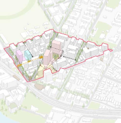
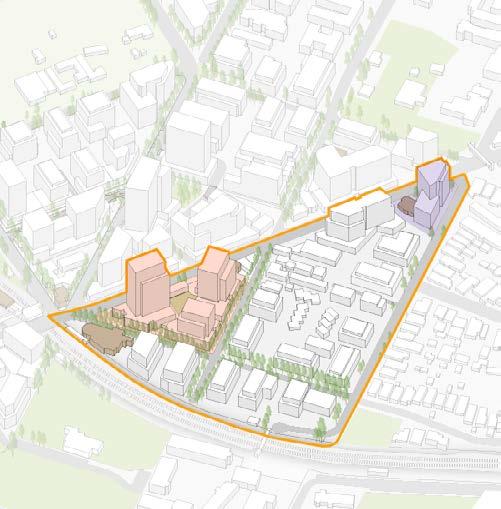
The Structure Plan provides an overview of the intended outcomes for the Local Centre. The Canterbury Local Centre Phase 1 Report informed the Structure Plan and based on the analysis of the opportunities, constraints and potential built form in Canterbury, consists of the following key elements:
• A new shared civic street with active edges on both sides of Robert Street.
• A new civic square, Canterbury Square, surrounded by high quality built form.
• New pedestrian links to provide good connectivity.
• An east-west cycle link proposed by the State government.
• Strengthen links to and from the Cooks River Pathway.
• Increased high density housing for apartment buildings to support and enliven the Local Centre
• Increased mixed use zoning to activate the Local Centre.
• Increased density in proximity to the railway and to open space.
• Increased open space located on the Cooks River and on the southern side of Canterbury Road.
The Structure Plan is shown in Figure 4.
Local Centre- mixed use zoning
Medium density residential
High density residential
New civic space
New civic space - location and dimensions subject to modeling carried out during the exhibition period.
Cooks River trail
High priority streets to increase tree canopy
Active edge
Active street frontage
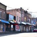
Historic shopfronts along Canterbury Road
Existing pedestrian through site link
Proposed pedestrian through site link
Existing laneway
Proposed new laneway
Planned East-West cycle link by State Government Agencies (location indicative)
Canterbury Road
Proposed High Street
Proposed Pedestrian connection above the metro line
Review traffic signal timing
Study Area
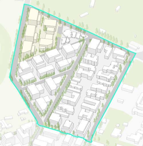
The Local Centre comprises four distinct character areas and a network of key streets and lanes, each with specific existing and desired future qualities. Applicants must identify the character area of their development site and demonstrate how their proposal responds to both the surrounding context and the future vision for that area and its street interface. A context and site analysis plan must be submitted with any Development Application to support this. A site analysis plan that demonstrates a context and site analysis is required with a Development Application to demonstrate understanding of the manner a site integrates with the desired character area.
The Local Centre is comprised of key streets with different desired future characters. The hierarchy, typology and character of streets will provide guidance as to how the building interface should be designed. As part of a Development Application, applicants must be cognisant of the desired future character of the street interface.
Canterbury Core:
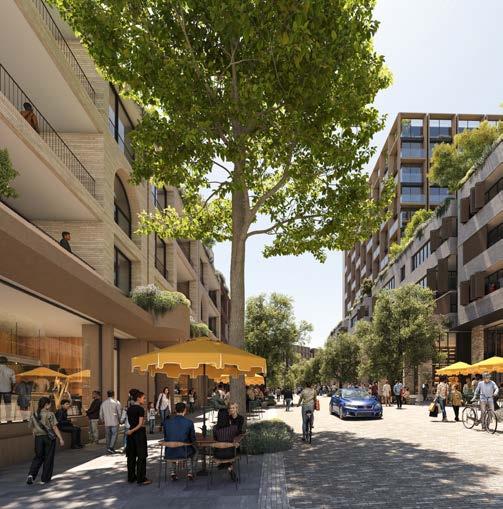
The Core will be the vibrant civic heart of the Local Centre, defined by a strong sense of place, new public spaces, and high-quality urban design. A new High Street along Robert Street, together with Jeffrey Street South and the future Canterbury Square (Canterbury Square), will create a welcoming, pedestrianfriendly precinct fostering a connected, engaged community. The Core will feature fine-grain retail, cafés, and dining experiences that bring energy and life to the street throughout the day and evening—supporting a thriving local economy. Taller buildings, softened with greenery and designed to a high architectural standard, will frame civic spaces and establish a strong local identity. The Core will be a walkable, inclusive, and lively destination.
P1. Development must achieve and satisfy the outcomes expressed in the identified character statement.
P2. Enhance pedestrian movement and support business activity by widening the footpaths.
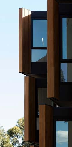
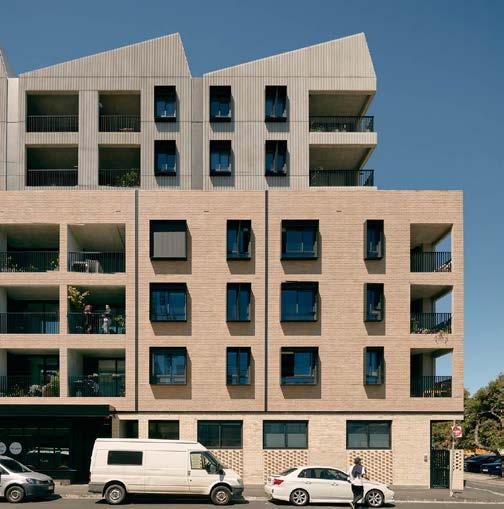
P3. Slender towers are designed with generous separation and a climate-responsive approach from all sides. Each façade responds uniquely to its orientation: the western façade is more enclosed, with vertical blades providing shade and reducing heat gain, while the northern façade is more open, with deep eaves and horizontal shading to welcome sunlight.
P4. Façade articulation is subtle and refined, using a restrained palette of materials and colours to convey simplicity and elegance. At street level, 3 to 4 storey podiums feature articulated facade where a mix of fine-grained shops, cafés, restaurants, and retail spill out onto the footpath, creating a vibrant, people-focused streetscape.
P5. Consider the design of the built form on the corner of Robert and Broughton Streets to assist with way finding from the Metro station to the central civic spaces.
P6. Facades should feature a higher solid-to-void ratio to reflect the local heritage character and integrate harmoniously with the surrounding context. The use of glazed balustrades and awnings is generally discouraged, as they detract from the desired materiality and context of the area.
P7. Ground-level facade treatment should contribute to a humanscaled, pedestrian-friendly streetscape that enhances the public realm and encourages activity and engagement.
P8. Developments should shape the built form to allow adequate sunlight into adjoining public spaces and incorporate depth and shade in facades to enhance visual interest.
P9. Awnings will provide a consistent height and width, typology/ materiality and detailing along all frontages within Robert Street and Jeffrey Street South and on the edges of Canterbury Square.
P10. Canterbury Square is the meeting place for the Local Centre. Buildings that surround the square must exhibit design excellence and set a benchmark for quality development. The Square must include public art and a playground. It should also be provided with shade for summer comfort, to be balanced with solar access to ensure trees grow and people can enjoy this community space all year round.
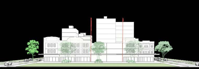
P11. Development along Canterbury Road should retain the two-threestorey historic street wall, with setbacks above. The buildings should revitalise the shopfront along Canterbury Road while ensuring connection to Canterbury Square, through features such as arcades and access points at the rear.
P12. Activation of Pierson Lane is essential to provide an activated edge to Canterbury Square and to allow for residents and visitor foot traffic into the Square from Canterbury Road.
P13. Street setback provide opportunity to widen the footpath to support growing number of pedestrians, outdoor dining and trading, expanded street tree planting.
The desired future character for key streets and lanes within the Canterbury Core is outlined as follows:
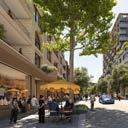
Robert Street – A new civic street located within a very short distance from the Metro station will become the main destination of the precinct. Both sides of the street will be activated by fine grained shopfronts and tenancies who will attract a diverse range of residents and visitors to linger, shop and access a range of daily services. The footpath will be widened to support the increase in pedestrian traffic and provide local business with outdoor dining and trading opportunities, increase tree planting. The towers above carefully articulated podium will be designed to maximize sunlight access to the street.
Robert Lane – A new two way service and pedestrian lane from Robert Street that continues as a pedestrian and cyclist lane through to John Street providing pedestrian permeability through to the racecourse. The intersection with Robert street will be activated by the ground floor tenancies who will spill out into the laneway, while access and servicing will be located at the back, optimising the active frontages along Robert Street.

Jeffrey Street South – is a civic and transit street that carries public transport and provides the main access to the new 1,500m² central square, Canterbury Square. The southern end of this street works in conjunction with Robert Street to form the Central Core for the Local Centre with shopfronts, tenancies and businesses activating the street. The northern part is residential, transitioning towards Canterbury North.
Pierson Lane - This laneway is located at the rear of the Canterbury Road sites. Forming a more intimate space that the other streets, the lane provides a secondary frontage for development on Canterbury Road and Jeffrey Street and provides rear lane access balancing activation with waste collection, deliveries and other servicing requirements.
John Street - John Street has a northern interface with the Canterbury Park Racecourse. The southern edge of this street will have new apartment buildings, providing residential density to the Local Centre in proximity to the Metro.
Canterbury Road - Canterbury Road is an important arterial but also currently lacks amenity. Leveraging the unique character of Canterbury, the historic shopfronts will be retained and integrated into the new developments. The towers will be generously setback above the podiums to maximise the amenity to the residents.
Canterbury North:
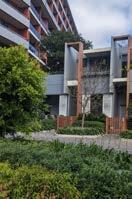
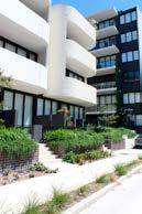
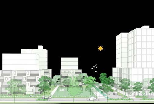
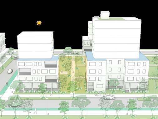
The desired future character is a green,leafy medium-density residential neighbourhood featuring apartment buildings of six to eight storeys set within a well-landscaped environment to create a liveable and attractive setting.
Well designed, generous landscaped setback along King street will establish a high quality street interface and enhance the amenity of both the public domain and the developments .
Landscape nodes on the corners of triangular sites will further reinforce the green and leafy character pf the area.
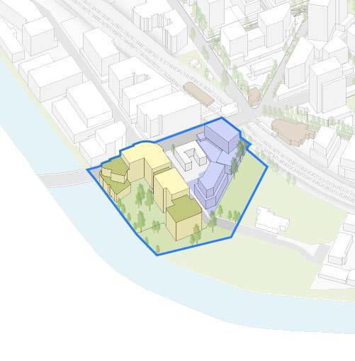
Key Site 1 presents a major opportunity to deliver quality homes in a well-designed, leafy urban setting, acing as gateway to the North of the local center.
P1. Development must achieve and satisfy the outcomes expressed in the above character statement.
P2. Apartments at street level provide individual entries to provide residents ownership to dwellings and to activate the street frontage.
P3. Apartments on King Street have a 6 metre front setback to allow for mature trees to grow in deep soil and provide a buffer to the busy road.
P4. Where blocks are irregular, such as Jeffrey Street North, allow for a 3m front setback for deep soil landscaping for mature trees. The corners of triangulated points of blocks should provide landscape nodes with deep soil for a mix of shrubs and mature trees to grow.
P5. Existing older apartment buildings with mature trees on the eastern edge of Jeffrey Street North contribute to the green, landscaped character that supports the area’s desired future character.
P6. Key Site 1 will provide internal pedestrian connections through the site.
The key streets within Canterbury North are Jeffrey Street North and King Street.
Jeffrey Street North - This is a neighbourhood street with apartment buildings of up to six storeys in height. The interface to existing apartments on the eastern side of the street provides openness and existing trees.
King Street - King Street aligns with the eastern boundary of the Canterbury Park Racecourse and has mature street trees. The street is a transit street that provides bus-public transport from the railway station through to Jeffrey Street and has an existing cycle link.
Canterbury East:
Canterbury East will have a mixed-use zone fronting on to Canterbury Road with setbacks and a landscape buffer to be employed where possible to provide better amenity for pedestrians. New apartments will feed into these commercial frontages that are located within 400m of the rail station. Behind, to the east, will be high density residential uses.
The desired future character area will include KS-4 at the corner of Canterbury Road and Tincombe Street which will be a mixed use, high density residential development that will provide community benefit in the form of pedestrian laneways and a new 500m2 civic plaza. This development will pull pedestrian away from noisy Canterbury Road and through to the Core and railway station.
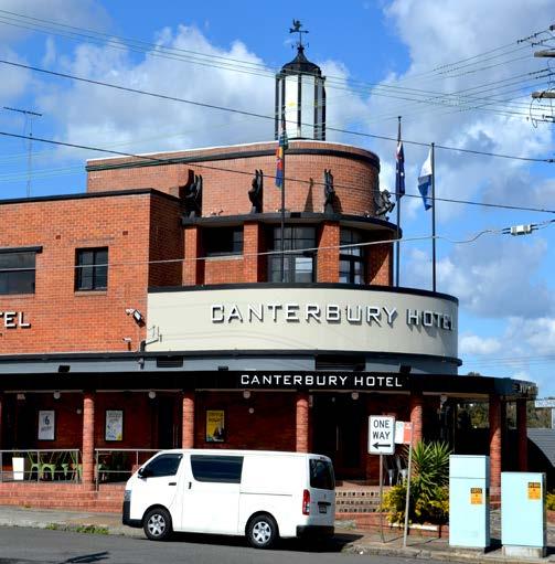
A second key site, KS-6, is located at the corner of Canterbury Road and Church Street. There is a mix of strata and heritage within this character area.
P1. Development must achieve and satisfy the outcomes expressed in the above character statement.
P2. Existing sites within this area are a tapestry of strata, heritage and single ownership large sites. New developments will provide sensitive interfaces to those sites through massing, landscape and material treatment.
P3. The eastern boundary to the character area is low density residential. A sensitive transition to the established R3 zone should be provided.
P4. A new pedestrian laneway to be provided for access from Minter Street to Canterbury Road.
P5. The Canterbury Hotel is a heritage item that has sat proudly in the public domain for many years. In any development, particularly the key site to the north, views to and from this hotel must be retained. Development must be setback away from the item at the corner of Canterbury Road and Tincombe Street in acknowledgment of the significant presence this building has in the public domain.
The desired future character for the key streets in Canterbury East include:
Tincombe Street - The desired future character of the Tincombe Street is to increase residential density and provide a landscaped setback, and respond to heritage in its materiality and architectural expression.
Church Street - The desired future character for the western side of Church Street is for low and medium density residential development with generous landscaped setback providing large tree canopy cover and greenery to the street.
Canterbury South:
This desired future character area is to enhance the interface with Leslie Muir Reserve and the Cooks River and establish fine grain shopfronts on Canterbury Road. Key site 5 is located in this area, will activate a new park and provide a pedestrian laneway from Canterbury Road to this new open space. The area has an old substation building and an existing block of walk-up flats fronting Canterbury Road. There are existing green links through to the heritage listed Sugar House buildings.
Close Street is the main street in Canterbury South along with the open space frontage from Key Site-5.
Close Street - A small industrial area on the southern side of Canterbury Road with an older residential flat building. Key site 5 is located to the north of Close Street and will have active frontage to a new open space. A new pedestrian link will be created from Canterbury Road through to the new open space and the existing Leslie Muir Reserve.
New Laneway
Train/Metro Line
Canterbury South
Cooks River Pathway
P1. Development must achieve and satisfy the outcomes expressed in the above character statement.
P2. The two key sites will create unique developments that are responsive to the natural environment, heritage and open space.
P3. The materials of newly proposed buildings should consist mainly of a simple palette of face brick or off form concrete with timber detailing. The facades should have a high masonry to void ratio to tie into Canterbury’s heritage. Render is not supported.
P4. Glazed awnings and balustrades are not supported.
P5. Landscaping is employed at the interface with Canterbury Road. Shopfronts should interface with the through site link to provide activation.
P6. A new pedestrian laneway provides a connection between Leslie Muir Reserve and Canterbury Road.
O1. To take a Country centred approach and thinking that is layered into new development in the Local Centre consistent with the Government Architect NSW ‘Connecting with Country framework’ (CWCF).
O2. To integrate Aboriginal cultural practices, history, narratives, and values in the design of proposed development.
O3. To encourage development to respond to the physical and cultural connection of the local Aboriginal community to the land.

G1. For development where clause 6.15 of the Canterbury-Bankstown
Local Environmental Plan 2023 applies, the development must demonstrate:
(a) how the design considers aspects of Country under Sections 3 and 4 of the Government Architect NSW ‘Connecting with Country framework’;
(b) how the design gives regard to the culture and heritage of the traditional custodians of the land, the Darug People, on which the development is proposed, including;
(c) connecting design with the existing site topography, natural environment and landscape setting,
(d) incorporating sustainable practices by using natural building materials.
G2. For development where Design Excellence clause of the Canterbury-Bankstown Local Environmental Plan 2023 applies, the development must determine the appropriate scope of engagement with the Aboriginal community and its representatives, whether it be high, medium or low as outlined in Section 3.1 of the Government Architect NSW ‘Connecting with Country framework’. If engaging with the Aboriginal community, development must:
(a) demonstrate the methods and outcomes from engagement with the Aboriginal community, (b) adhere to protocols outlined in the NSW Government’s Practice
Note ‘Engaging with Aboriginal Communities’ and ‘Aboriginal Cultural and Intellectual Property Protocol’.

G3 If significant items such as ancestral remains or artefacts are discovered during subsoil investigations, excavation, demolition or other earthworks, the applicant must engage with the Aboriginal community to determine culturally appropriate handling, repatriation or reburial.
G4. Development that proposes open space and landscaping should demonstrate consideration of ‘walking Country’ which reflects Aboriginal cultural practices, artefacts, artwork and narratives. Aspects involving the senses of seeing, hearing, touching, smelling and tasting, should be included.
G5. Design aspects of each development should give regard to the culture and heritage of the traditional custodians of the land, the Darug People, on which the development is proposed. The following design opportunities should be considered to ensure a Country-centred approach:
(a) Connect design with the natural environment and landscape setting, being: people, animals, resources and plants equally.
(b) Acknowledge shared history between Aboriginal and colonial settlers to promote healing and reconciliation by incorporating storytelling and knowledge of the past.
(c) Incorporate sustainable practices by using natural building materials that have a cultural and heritage significance.
(d) Incorporate Aboriginal place names, as guided by the Geographic Names Board, to foster understanding and raise awareness.
(e) Focus on details and patterns to insert cultural meaning.
G6. All work prepared to address the Connecting with Country objectives and design guidance must address the NSW Indigenous Cultural and Intellectual Property Protocol, to ensure applicants are aware of their duties with respect to the integration of this content.
Public space includes streets, squares, parks, through site links and laneways. Public spaces are the enduring elements of a city or place which people share as social and cultural space. These civic elements form the framework for the Local Centre and work in cooperation with the built form interface on private land to enliven and create a unique place inclusive to all people. To ensure for a high-quality functioning Local Centre, a public domain framework is essential, working together with the built form interface to create engagement, interest and elevating the pedestrian experience.
' A humane city-with carefully designed streets, squares and parks creates pleasure for those who live, work and play there every day, as well as visitors and passers-by. Everyone should have the right to easily accessible open spaces, just as they have the right to clean water. Welldesigned neighbourhoods inspire people to live in them.’ Richard Rogers.
The key public domain improvements for the Local Centre were derived from in depth urban design analysis. The key parts to the strategy include:
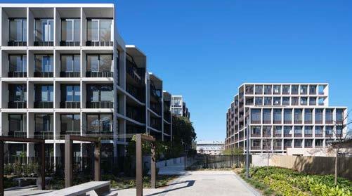
1. A new civic square, Canterbury Square, is proposed at the heart of the Canterbury Core. The square will accommodate community life and invite people to experience the Local Centre. The square will be edged with active uses to engage pedestrians while having spaces for repose and for active play. Solar access will be balance with shade and a tree canopy requirement will ensure for mature tree growth. Pierson Lane is extended North to free the new civic square from traffic.
2. Robert Street is to be transformed into a shared high street with active frontages on both sides. A new laneway is proposed connecting Robert Street with John Street to provide waste servicing away from the high street and to provide a mid-block pedestrian laneway through to John Street.
3. Improve pedestrian and cycling connectivity. Provide laneways and arcades to create a fine grained
pedestrian network. Improve and extend the existing cycle network. This includes providing additional off road cycleways connecting with the broader network. Enhance existing laneways with lighting and landscaping to make them safe and welcoming.
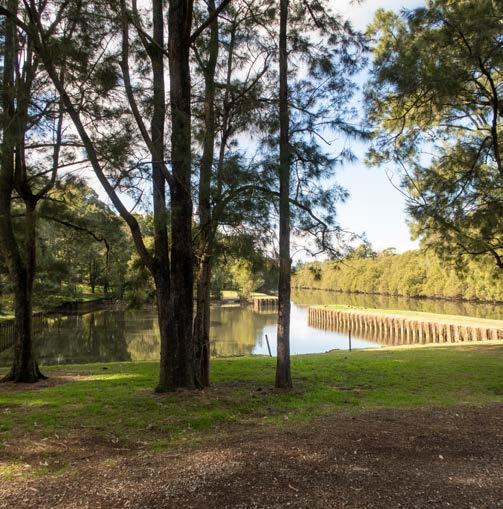
4. Enhance existing public domain assets. These include Warwick Reserve, Leslie Muir Reserve and the Cooks River active transport corridor.
5. Increase and maintain existing tree canopy cover and provide green cover. Tree canopy and green cover requirements apply to new development with new trees to be provided on private land and in the public domain. Green cover to development will be provided to ensure for softening using landscaping, greening podium and communal spaces and green walls.
6. Provide for new public open space to extend Leslie Muir Reserve within the Canterbury South character area.
7. Enhance pedestrian environment and support business activity by widening the footpaths in the center.
Primary shared path
Secondary quiet way
Public domain strategy
Proposed shared path links
Existing pedestrian and cycle links
Primary cycling network, off-road
Proposed laneways
Secondary cycling network, on-road quiet way
Proposed pedestrian crossing
Future primary cycling connection for investigation, off-road
Cooks River Trail
Proposed pedestrian and cycle through site links
Planned East-West Cycle Link by State Government (indicative)
Existing pedestrian and cycle links
Proposed laneways
Existing laneway
Proposed pedestrian crossing
Alternative route for East-West Cycle Link by State Government (indicative)
High priority street for increasing canopy coverage
High priority street for increasing canopy coverage
New civic space
Future primary shared path connection
New high street, shared space
Active frontage
Future crossing upgrades
Study Area
New civic space
New high street
Refer to Indicative public domain plan
Future crossing upgrades
Alternative route for East-West Cycle Link by State Government (indicative)
Planned East-West Cycle Link by State Government
This indicative plan illustrates a high level vision for the new civic heart of the precinct. This plan is for illustration purposes only, final configuration (including but not limited to material, tree type, number and location, car parking bay number and location, intersection design, street furniture) will be subject to future design development and other considerations.
Property boundary
Awning line above
Building footprint
Robert Lane is a new laneway providing access and servicing to Robert Street developments ensuring continuous fine grain retail experience along the street.
Street setbacks provide extended footpath space for pedestrian and businesses, anchoring Robert Street as the new high street of the Core.
Intersection upgrade with raised intersection, new pedestrian crossings and extended verge. Subject to future design and transport considerations.
Playground Jeffrey Lane
Pedestrianisation- a new laneway will provide vehicle access around the building north to the plaza
Public spaces are provided on public land and include squares, parks and streets, whereas publicly accessible space is located on private land and can be accessed by the public as a laneway, a square or a shopping arcade.
O1. To ensure that the size, type, accessibility and program of open spaces accommodates the future number of residents, workers and visitors and their recreational and passive needs throughout the day and night.
O2. To create new connections to open space to ensure residents, workers and visitors have easy, convenient access by walking and cycling to existing and proposed open space.
O3. To provide for inclusive and welcoming new open space and publicly accessible open space in underserved areas and upgrade existing open space.
O4. To ensure private development contributes to meeting the recreation needs of residents, workers, students and visitors.
O5. Ensure that any proposed privately owned publicly accessible space have a full public nature equivalent to the public domain.
O6. To ensure development contributes to a diverse network of quality and attractive open spaces comprised of well-connected parks and squares, green streets and laneways.
O7. To ensure open space has a high level of solar access and shade that is suitable to purpose.
O8. To establish a vibrant and attractive center where the network of streets, laneways and open space is supporting the increase in pedestrian movement and footpath trading activities from the growth in development.
P1. Provide equitable access and a variety of amenity and recreational options to accommodate different community needs.
P2. The design of new open space should use a palette of high quality and robust materials to maximise design lifespan and create beautiful places. Landscaping treatments and material selections must respond to the local character of each space and contribute to a cohesive and unified public domain throughout the town centre.
P3. Create and enhance natural ecologies within the urban fabric through the use of diverse native landscape species.
P4. Paths of travel through public open space must respond to ‘desire paths’ and should be lit in the evening to improve safety and accessibility for users.
P5. In high activity area where street space and footpath are constrained, create a suitable environment for pedestrian movement and business activity by widening existing footpath into private land.
C1. Development must provide frontage and address to engage with open space and publicly accessible space. This can be achieved by but is not limited to:
(a) ground level active frontage, (b) balconies addressing open space, and (c) access from development sites and laneways to and from open space.
C2. Buildings, (except for awnings), and building basements, are not permitted to be located on, above or under any proposed new open space.
C3. Where development is required to provide widened footpath areas as per figure 20, the footpath area is to be designed and constructed as an extension of the existing footpath, unencumbered of physical obstacle to facilitate pedestrian movement, street tree planting and business activity.
C4. Public art must be integrated into publicly accessible open spaces and located in accordance with the locations identified in Figure 20. The design and placement of public art must contribute meaningfully to the character, identity, and activation of the public domain.
C5. Where required by Council, publicly accessible space must be provided in the locations identified in Figure 20. The provision of publicly accessible space is to be delivered in accordance with the specifications outlined in table 1.
Primary shared path
Publicly accessible spaces map
Secondary quiet way
Proposed shared path links
Existing pedestrian and cycle links
Proposed laneways
Proposed pedestrian crossing
Cooks River Trail
Planned East-West Cycle Link by State Government (indicative)
Alternative route for East-West Cycle Link by State Government (indicative)
High priority street for increasing canopy coverage
New pedestrian and cycle through site link - 4m to 6m wide easement as per LEP.
Future primary shared path connection
New shared laneway (pedestrian, cyclist, vehicle access and services) 6m to 9m wide easement as per LEP.
Active frontage
New publicly accessible open space - Civic Square 1500m².
New civic space
New high street
New publicly accessible open space - Civic Plaza 500m² - Location and dimensions subject to modeling carried out during the exhibition period.
Widened footpath area - Extension of the footpath as per street setback control in the E1 center to accommodate increased footpath traffic, street tree planting and outdoor trading activity from growth in development.
Future crossing upgrades
Map legend Type of publicly accessible space Delivery mechanism Ownership Asset management and maintenance Accessibility
Asset are to be designed to:
Pedestrian and cycle through site link - 4m to 6m wide easement as per LEP. LEP bonus incentive Through-site links are to be an easement on title.
Shared laneway (pedestrian, cyclist, vehicle access and services) 6m to 9m easement as per LEP.
LEP bonus incentive
Land owner
a) Be fully accessible to the public 24 hours a day.
b) Ensure that buildings or structures (other than awnings) are not located over any proposed through-site link.
New shared laneways are to be dedicated to Council prior to a final Occupation Certificate being issued. Council reserves the right to not accept dedication and any proposed dedication must be discussed at a prelodgement meeting. Land owner or council As above
Publicly accessible open spaceCivic Square 1500m² LEP bonus incentive Land owner with positive easement on title. Land owner As above
* Publicly accessible open spaceCivic Plaza 500m² LEP bonus incentive Land owner with positive easement on title. Land owner As above
Widened footpath areaExtension of the footpath as per street setback control in the E1 center to accommodate increased footpath traffic, street tree planting and outdoor trading activity from growth in development.
Condition of consent Land owner with right of way
Table 1: Legend explanation of publicly accessible map of Canterbury.
Land owner or council
Asset are to be designed to be fully accessible to the public 24 hours a day.
Primary shared path
Secondary quiet way
Proposed shared path links
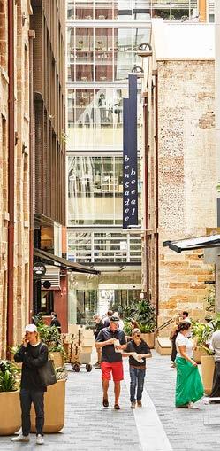
Laneways and through site links prioritise pedestrians and cyclists, are open to the sky and have awnings. Through site links are for pedestrians and cyclist only while laneways are shared with service vehicles and access. Arcades are internalised retail ‘lanes’ which provide permeability through development and often an engaging retail experience. Through site links and arcades are usually narrow, more intimate spaces for pedestrians to linger in and provide a connection through a street block to reduce walking distances.
Existing pedestrian and cycle links
Proposed laneways
Proposed pedestrian crossing
Cooks River Trail
Planned East-West Cycle Link by State Government (indicative)
Alternative route for East-West Cycle Link by State Government (indicative)
Cross section reference - figures 24 to 30
New through site link - 4m
High priority street for increasing canopy coverage
New through site link - 6m
Future primary shared path connection
New shared laneway (pedestrian, cyclist, vehicle access and services) 6m
New shared laneway 9m
Active frontage
New publicly accessible open space
New civic space
Primary cycling network, off-road
New high street
Secondary cycling network, on-road quiet way
station
Future primary cycling connection for investigation, ff-road
Future crossing upgrades
Cooks River Trail
Alternative route for East-West Cycle Link by State Government (indicative)
Planned East-West Cycle Link by State Government
O1. To provide a high quality, safe, connected cycle network that enables the community to choose to ride to work, home or a destination.
O2. To improve connectivity for pedestrians and cyclists between key destination points.
O3. To ensure laneways, through site links and arcades are accessible, attractive, continuous, well-lit, safe and where appropriate, open to the sky.
O4. To provide amenity and safety to existing and proposed laneways, through site links and arcades, and active uses to engage pedestrians, where appropriate.
O5. To design laneways, through site links and arcades that provide an intimate space to linger within a fine grain spatial network.
O6. To provide for vehicular entries and servicing away from primary street frontages using service lanes.
C1. Where required by Council, laneways, through site links and arcades must be provided in the locations identified in Figures 21, as per figure 23 to 30. These connections must be designed to ensure permeability, safety, and integration with the broader movement network.
C2. Laneways and through site links are to be designed to:
(a) Have a minimum width of 4m and cater for the movement of pedestrians and cyclists in both directions.
(b) Ensure that buildings or structures are not located over any proposed laneway, other than awnings.
Urban Neighbourhood Street
(c) Provide lighting, paving, street furniture and tree planting to clearly indicate the priority of the pedestrian or cycling user, (to be provided in accordance with Council’s specifications and design standards).
(d) Development must demonstrate the provision of physical and visual connections with neighbouring sites, including any necessary level adjustments. Detailed plans illustrating these connections are to be provided as part of the development application.
(e) Awnings must be provided for weather protection, offering shade and shelter from sun and rain. Awnings are to be designed and delivered in accordance with the requirements specified in Section 4.3.2 of this DCP.


(f) Stormwater management measures must be incorporated to minimise the flow of pollutants from the laneway. Treatments must be implemented in accordance with Section 3 – Stormwater Drainage Systems of the Canterbury Bankstown DCP 2023.
(g) Be clear of all obstructions, including stairs, escalators and columns and provide a clear line of sight from one end to the other for surveillance and accessibility, and
(h) Outdoor laneways and through site links will be open 24 hours a day, well-lit and adhere to the Crime Prevention Through Environmental Design (CPTED) principles.
(i) Where a development has the potential to create a laneway through block connection by extending an existing or proposed lane within its site, the lane should be completed or extended within the development site. If a development can deliver part of a lane or initiate a new lane, it should make provision for it.


C3. Through site links are to be an easement on title. New shared laneways are to be dedicated to Council prior to a final Occupation Certificate being issued. Council reserves the right to not accept dedication and any proposed dedication must be discussed at a pre-lodgement meeting.
C4. The maintenance of the laneway and through site link in perpetuity including cleaning, repairing and replacing damaged or worn paving, furniture and the like and maintaining landscaping in a healthy condition is the responsibility of the land owner, not Council. A management plan must accompany any development involving the provision of a laneway. The plan is to demonstrate how ongoing access, maintenance, and functionality of the laneway will be ensured, including through any future changes in ownership.


Controls (continued)
C5. Arcades within retail and commercial developments are to be designed to:
(a) Be two storeys in height or where proposed as a single storey ground level, have a minimum floor to ceiling height of 6m, (refer to Figure 30).
(b) Have Widths of 4m – 6m where the links are provided within a two storey height, or 5m – 8m wide where provided at a single floor level, (refer to Figure 30).
(c) Be located at ground level and lined with spaces to facilitate active uses.
(d) Be designed to have access to natural light.
(e) Be open at each end or, where air conditioned, provide entry doors that are glazed and comprise a minimum 70% of the width of the entrance,
(f) Be publicly accessible from 6am to 10pm each day.
Note:
Trees are essential for their contribution to the amenity and character of the Local Centre. When appropriately selected, located, planted and maintained, trees provide a multitude of benefits to the urban environment including reducing heat gain, providing shade and mitigating climate change.
Objectives
O1. To provide tree canopy for shade to maximise amenity to public space during the periods of the day they are most used for recreation or repose.
O2. To improve and enhance environmental biodiversity and mitigate heat at ground level.
O3. To ensure for maximum tree canopy in development and performance on private land and public land.
O4. To create a contiguous tree canopy, to mitigate climate change and to improve the health and wellbeing of people and ecosystems.
O5. To provide green cover to soften the building form, create amenity for occupants and provide for a green aesthetic to the public domain.
Principles
P1. To ensure existing trees are protected and that additional trees are planted in the public and private domains.
P2. Provide tree planting appropriate to the local climate.
P3. Provide for recreational equipment, seating, landscaping, absorptive ground treatments and an integrated consistent material palette for hard landscaped areas.
C1. As part of any Development Application for residential, mixed use or non-residential development, street trees are to be provided to all public frontages to the satisfaction of Council.
Streetscape Element Indicative Minimum Clearance
Street Intersectionapproach side 10m from intersection kerb line
Street Intersectionnon-approach side 7m from intersection kerb line
Traffic Signals >10m from signal pole on approach side
Bus Stops 3m
Pedestrian Crossings- approach side 10m
Pedestrian Crossings- nonapproach side 7m
Shared Lanes 1m
Driveways- approach side 3m
Driveways- nonapproach side 2m
Stormwater Inlet/ Outlet 2m
Street Light Pole 3m
Underground Service Pit 1m
Table 2: Indicative minimum clearance of streetscape elements
Cycleways 0.5m
C2. New street trees must have a minimum pot size of 75 litres but no greater than 200 litres.
C3. Street trees should be planted with clearances as set out in Table 2 on p43.
C4. Minimum tree canopy cover is required on private land as per Table 1.
C5. Tree canopy cover refers to the layer of leaves, branches, and stems of trees that cover the ground when viewed from above, expressed as proportion of the total site area, calculated in accordance with the following:
(a) Canopy area is to include the expected mature size, (crown spread at maturity), of existing and proposed trees.
(b) Only trees with a minimum crown spread of 3m in diameter are to be included. Trees with a crown spread less than 3m diameter are to be excluded from tree canopy cover calculations.
(c) Any overlap in canopy area is to be counted once.
Within B2 Local Centre Zone
Within R2 Low
Density Residential Zone, R4 High Density Residential Zone
Table 3: Minimum tree canopy cover for private land.
(d) Canopy area extending outside of site boundaries is to be excluded.
(e) Canopy area extending within a development site from trees planted in adjoining sites is to be excluded.
(f) Trees located over structures, including podiums and rooftops, are to be included.
C6. The design of the canopy trees should be laid out such that sufficient room is provided for the trees to achieve their desired mature size. Canopy overlap should not exceed 25%.
C7. New development within the B2 Local Centre, zone must deliver 50% of the site area as ‘green cover’ which can be any combination of the following:
(a) Deep soil zones
(b) Landscape areas
(c) Layered planting on structure (including small and medium trees, as per the Apartment Design Guide)
(d) Green roofs and awnings
(e) Permanent planting on balconies and podiums, (including built-in planter boxes).
Note: Photovoltaic (solar) panels are permitted on rooftop areas; however, they cannot be counted towards green cover or replace required green cover. Planting may be provided around the panels.
O1. To ensure for solar access to parks and spaces for the enjoyment of residents and visitors.
O2. To balance sunlight access to the principal useable parts of public open space with shaded areas to enable a range of activities and the planting of a variety of trees and vegetation.
O3. To maintain or maximise solar access to public space during periods of the day when they are most used.
O4. To ensure the successful growth and survival of trees and vegetation within parks and spaces.
P1. Provide high levels of solar access to ensure that tees and vegetation in public open spaces and publicly accessible open spaces thrive, amenity for the community and warmth in winter sun.
P2. Provide solar access on balance with shaded areas to ensure for amenity to all users all year around.
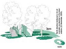
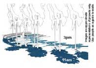
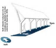
C1. Development Applications must demonstrate that the hours of solar access outlined in Figure 31 are maintained or preferably exceeded.
C2. Where overshadowing of parks and spaces is likely, a statement with supporting solar access studies must be submitted by a registered architect demonstrating that the proposed development mitigates overshadowing to the affected open space or publicly accessible space.
C3. Ancillary structures such as columns, pillars, spires, flag poles, public art, and architectural roof features including equipment for servicing the building, such as plant, lift motor rooms, fire stairs and the like, must not be excluded from any overshadowing analysis.
Note: Please refer to Section 6 Key Sites for more detailed controls for Jeffrey Street.
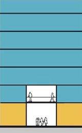
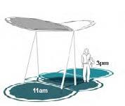
Minimum 2 hours of sun for 50% of the open space in the winter solstice in Civic Plaza.
Minimum 4 hours of sun for 50% of the open space in the winter solstice.
Minimum 5 hours of sun for 50% of the open space in the winter solstice.
Canterbury experiences a relatively high urban heat island effect due to climate change and a low tree canopy cover. This means the combination of roads, other infrastructure and buildings without many trees and a hot climate result in the absorption of heat in the Local Centre which re-radiates and increases temperatures. Summer temperatures reach to over 35 degrees Celsius and have reached 45.9 degrees in the past. Australia has one of the highest incidences of skin cancer in the world.
Shade refers to areas shielded from direct sunlight, often provided by natural elements or structures and is crucial for comfort, UV protection and promoting social activity. Shade can work together with water, permeable paving, ground cover and material selection to reduce heat gain. Shade and seating, together, support healthy communities, socially and economically.
For the Local Centre to be pleasurable to all users, there needs to be a focus of the provision of shade, balanced with solar access, through imaginative design implemented in public space and publicly accessible space.
O1. To ensure for refuge from hot summer sun in public and publicly accessible open space.
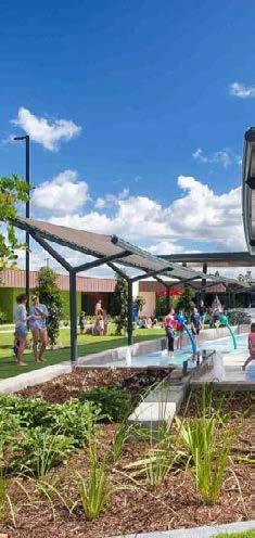
O2. To create imaginative responses for shade that integrate with playgrounds, water features and areas for the community to congregate in.
O3. To ensure for high amenity public and private spaces that are pleasurable to use.
O4. To reduce the contribution of new development to the urban heat island effect by retaining and providing design elements that store water, minimising impermeable surfaces to increase rainwater infiltration and allow for the improved cooling effects of evaporation.
O5. To improve user comfort in public domain and space accessible to the public.
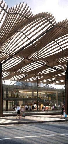
P1. Create shade linkages through implementing shade structures, awnings to shop fronts and planting trees.
P2. Integrate water features such as misting, sprays and water fountains and the like where shade is provided in public and publicly accessible open space.
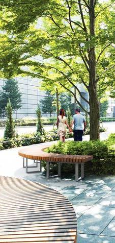
P3. Consider the location of trees and structures and the resultant shadow that will be created. Locate seating and areas where people can rest in these shaded areas.
P4. Maximise greenery throughout the Local Centre to reduce urban heat.
P5. Shade paved surfaces and walls where possible but also consider solar access in winter months
C1. Refer to Section 6- Key Sites for shade requirements for Canterbury Square.
C2. Retain existing trees to maintain shade.
C3. Improve cooling by locating trees to provide shade to exposed building walls, hard surfaces and pedestrian walkways.
C4. Use trees and shade structures in combination with water features to reduce temperatures in public open space and publicly accessible spaces.
C5. Store water in the landscape using fountains and water play features and the like.
C6. If a dark roof is used, green cover must cover the roof form. Consider reflectivity in the choice of roof material and the colour.
C7. Minimise the reflection of solar heat from facades by selecting appropriate materials.
A minimum lot size for certain residential dwellings is proposed to ensure lots are large enough to accommodate certain residential development, particularly residential flat buildings, and maintain adequate frontage and amenity.
O1. Ensure lots for residential accommodation are large enough to accommodate proposed dwellings, setbacks to adjoining residential land, private open space and landscaped areas, driveways and vehicle manoeuvring areas,
O2. Ensure lots for non-residential accommodation are large enough to accommodate setbacks to adjoining land, private open space and landscaped areas, play areas, pedestrian access, set down and pick up areas, car parks, driveways and vehicle manoeuvring areas,
O3. Minimise the likely adverse impact of development on the amenity of the area,
O4. Require lot amalgamation to achieve minimum lot frontage and size requirements,
O5. Ensure lots are large enough to protect special attributes, including natural or cultural features, heritage items, heritage conservation areas, trees and natural topographical features,
O6. Prevent fragmentation or isolation of land.
C1 Development consent must not be granted to development above 8 storey on land specified in Column 1 of the table to this subclause for a purpose specified in Column 2 unless—
(a) the lot is at least the size specified in Column 3, and
(b) the width of the lot at the front building line is at least the width specified in Column 4.
Zone E1 in Area 9 (except where a lot has a secondary frontage or access via a laneway)
Zone E1 in Area 9 (except where a lot has a secondary frontage or access via a laneway)
Zone E1 in Area 9 (except where a lot has a secondary frontage or access via a laneway)
flat buildings -
4.2.1 Building height and storeys
The building heights in the Local Centre:
⚬ Provide for the intensification of development around the station to maximise housing provision.
⚬ Minimise overshadowing to existing and proposed open spaces.
⚬ Provide for landmark buildings on prominent corners to improve the legibility of the Local Centre.
O1. To design a distinctive and legible skyline to define the core of the Local Centre.
O2. To design tall buildings that allow for adequate provision of sunlight to streets and squares for pedestrians and to allow trees to grow.
O3. To ensure that buildings are designed in consideration of wind impacts to the public domain.
O4. To design elegant slender towers that have considered views from the Cooks River and the new Canterbury Square.
O5. To ensure tall buildings express a strong architectural response defined by a clearly identified concept or idea to create a sense of place.
P1. Concentrate tall buildings around the Metro station and civic areas.
P2. Ensure that towers over 25m are setback above a podium to mitigate bulk and dominance of the street.
P3. Ensure the height and scale of new developments are site specific and developed in response to key features of the site and setting.
P4. Ensure wind conditions promote outdoor planting, including green roofs and other landscaping elements as well as tables, chairs and other furniture used by building occupants on balconies and outdoor areas on buildings.
C1. A wind impact assessment is required for:
(a) Buildings over 25m in height,
(b) Buildings without a podium on a corner sites.
C2. Buildings without a podium are permitted on corner sites. In cases where a podium is not proposed, the building is to:
(a) Be designed to mitigate down drafts to the public domain in accordance with a Wind Impact Assessment report;
(b) Be designed ‘in the round’ (i.e. consideration of the design quality in relation to how the building is viewed from within the Local Centre, from the street level, from within other buildings and from a distance);
(c) Provide a high-quality ground plane for pedestrians at street level.
C3. Development must not exceed the number of storeys shown for the site on figure 40 Building Height in Storeys Map.
O1. Ensure that floor to floor heights provide adequate amenity for building occupants, support a different range of uses and allow for flexibility of uses over time.
O2. To ensure the ground floor of buildings have a consistent floor to floor height to provide a wellproportioned and quality interface to the public domain.
P1. The entire ground floor level should be at same floor to floor height to ensure for a consistent and attractive frontage.
P2. Notwithstanding the above, where a waste collection vehicle must entry from a mid block frontage, the finishing of the service cupboards and basement car park entry should be coordinated in dark recessive colours to minimise the visual impact on the public domain.
Controls
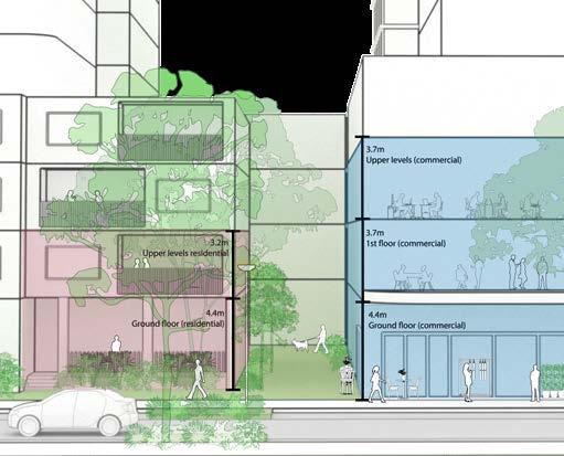
C1. Development must comply with the minimum floor to floor heights shown in Table 5. This control does not apply to dwelling house, dual occupancy, semi- detached dwellings or multi-dwelling housing development. For waste truck access – Heavy Rigid Vehicle (HRV) * 4.5m clearance for HRV
*This includes ground level and podium level car parking. If a development has basement waste collection facilities, minimum clearance must comply with the controls established in Chapter 5.5 .Waste management.
4.2.3 Street wall
Together with the public domain, the street wall with active ground floor frontage is the built element that shapes the way most of the city is experienced. The street wall provides spatial enclosure and must operate in concert with other street walls or podiums to form a satisfying and rich experience of the public spaces of the city for the community. Interruptions or erosions of the street wall generally work to undermine the vitality and definition of the street wall and are not favoured.
O1. To ensure that the visual relationship between the street and public space is reinforced.
O2. To design the street wall to achieve fine grain modulation to create visual interest and variety while ensuring for consistency in streetscape character.
O3. To create a vertical rhythm and visual interest to reduce the scale of building mass.
O4. To implement an articulation zone within podiums and facades to allow architectural form to develop.
P1. Street wall design should reflect the context and interface with a particular street typology.
P2. Design the street wall to provides appropriate scale, material quality and detail.
P3 Minimise large expanses of inactive frontage.
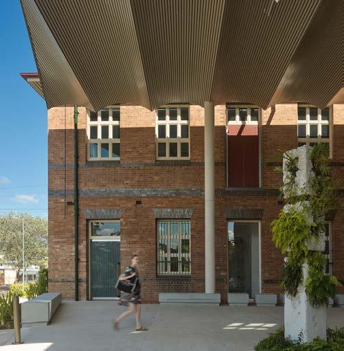
P4. Retain and sensitively integrate existing heritage and historic shopfronts into new development.
C1. Street wall heights must be consistent with Figure 45. For Council to consider a variation to a street wall height a development application must include a streetscape analysis that demonstrates a more appropriate street wall height. Submissions must include:
(a) The street wall elevation at 1:500 scale in context showing existing buildings on the block;
(b) A detailed street wall elevation at 1:200 scale including the buildings immediately adjacent.
C2. Where a street frontage length of an individual building exceeds 45m in length, it is to appear broken into two or more buildings each with different architectural characters. This outcome could be achieved through the following articulation design considerations or through other alternative design considerations to the reasonable satisfaction of Council:
(a) Podiums measuring greater than 45-70m in length are divided into two or more vertical elements.
(b) Vertical elements must be separated by indentations at a scale legible in the street and use a varied architectural expression and materiality.
(c) In cases where there is a range of heights in a street wall, prioritise the lower range along laneways, pedestrian links, and areas with high pedestrian activity.
C3. Where there are existing historic shopfront street walls, such as along the Canterbury Road frontage, these shopfronts should be sensitively be integrated into new development to the satisfaction of Council.
C4. Where the adjacent built form context is lowerscale and not anticipated to change,development must provide a transition to the lower scaled built form and include appropriate articulation to fit with the context.
C5. For sites including or adjacent to heritage items, development must transition the scale and height of the development and provide adequate separation and appropriate articulation to respect the scale established by the historic or existing context.
C6. Datums derived from listed heritage buildings on the site or on an adjoining property — that is, the heights of the main ridgelines (or parapets in the case of commercial buildings), top plates/eaves level (or awnings of commercial buildings) and ground floor levels (street or natural ground levels)—must be used to ensure composition of height and scale is visually harmonious.
4.2.4 Front setbacks
O1. To define streets, public spaces and key elements that including heritage and landscape features.
O2. To allow flexibility in setbacks where appropriate, minimising impacts on surrounding properties and the public domain.
O3. To enable sensory engagement with the street.
O4. To encourage setbacks that reinforce the desired future character of the area.
O5. To utilise front setbacks to provide privacy and amenity.
O6. To create a lively destination in the centre that caters for the growth in population and provides space for outdoor trading and dining, lingering, and increased tree canopy.
P1. Reinforce the Central Core by creating a defined urban street edge.
P2. To allow flexibility in response to context only where amenity and environmental impacts are minimal.
P3 Provide opportunities for landscaped 'nodes’ for medium and large trees at the corners of triangulated sites and courtyards at street frontages that will provide increased tree canopy and implement the Government Architect NSW ‘Biodiversity in Place’ principles.
P3 Set back the buildings in the buildings in the centre to widen the footpath area .
C1. Front setbacks are to be consistent with Figure 47.
C2. For landscape nodes shown at 9m from a corner on Figure 47, the setback should be taken from the midpoint of that corner.
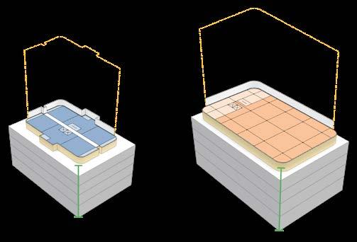
Figure 46: Diagram illustrating landscaped nodes and courtyard in triangulated sites with a L-shaped building typology - Not at scale.
4.2.5
O1. To ensure buildings are setback above street walls to reinforce the scale of streets, mitigate wind down drafts to pedestrians and mitigate dominance of the public domain.
O2. To ensure that upper storey setbacks allow for the enjoyment of sun and daylight within public spaces, provide for views of the sky and allow trees to grow.
O3. To provide for appropriate transition and sympathetic response to lower-scaled buildings and significant elements within the local context.
O4. To create opportunities for tree canopy, planting and outdoor open space on podiums.
P1. Clearly delineate the street wall and create a visual break in tall building facades.
P2. Encourage green cover and useable spaces on podiums and rooftops
P3. Promote generous commercial, communal and residential balconies on upper storey setbacks
P4. Buildings above the podium are setback from the street in a way that is sympathetic to surrounding development and does not detract from the human scale of the streetscape.
C1. Upper storey setbacks are to be consistent with Figure 48.
C2. Where there is no upper storey setback shown on the map, the upper-storey setback of existing development immediately adjoining the site must be adopted. Where there is insufficient existing development adjoining the site, the applicant is to demonstrate why the proposed setback is appropriate giving consideration to the Principles and Objectives of this Chapter.
C3. Building envelopes may require a deeper upper storey setback to protect sunlight and limit shadowing of neighbouring streets, properties, parks, and open space. A deeper upper storey setback may also be required for heritage items to ensure heritage significance is not compromised.
4.2.6
O1. To ensure sunlight penetrates through to street level to protect the amenity of pedestrians and allow street trees to grow.
O2. To ensure that taller buildings are not overwhelming and overcrowded and appear as distinct elements within the skyline with space around them.
O3. To provide adequate privacy, access to light, air and outlook to the sky for the occupants of buildings, neighbouring properties and future buildings.
O4. To ensure development does not unfairly limit the re-development potential of adjoining sites in the future.
Principles
P1. Building design should avoid using multiple upper-level setback ‘steps’ that result in a ‘wedding cake’ or a ‘ziggurat’ appearance.
P2. Maintain adequate separation distances between buildings on the same site to protect access to sunlight and sky views and improve air circulation between buildings.
P3 Provide separation to enable a building to be seen from all sides and to allow for articulation that responds to orientation.
C1. Minimum building separation distances for non-residential uses are outlined in Table 6.
Non-residential uses
(or 12m for tall buildings of 25m or more)
Commercial developments adjoining single purpose residential uses**
Note: In high streets where there are blank party walls, no separation is required.
**Commercial developments include business premises, childcare centres, educational establishments and places of worship. Single purpose residential uses include residential flat buildings, boarding houses, multidwelling housing and single dwelling houses.
For residential apartment development, please refer to the Apartment Design Guide(ADG).
4.2.7 Maximum floorplate area
O1. To ensure towers are not bulky, provide good amenity to building occupants and appear slender, elegant and well-proportioned when view from streets and from distance.
O2. To allow for views to the sky from streets and lanes.
O3. To reduce building bulk and minimise its impact on streets, public spaces, and street trees by mitigating adverse effects such as overshadowing and urban heat gain.
O4. To ensure floor plates are limited to a certain area and configuration in accordance with use.
Above 25m floorplate controls apply
Non-residential towers for commercial buildings with a maximum of 1.500m² of GFA.
P1. Tall commercial towers must prioritise daylight access and minimise solar heat load.
P2. Shallow floorplates and glazing to south facades are favourable for providing excellent natural daylight.
P3. Achieve living and working environments with good internal amenity and minimise the need for artificial cooling and heating.
C1. The maximum floor plate area for any levels above 25m above ground level must be:
(a) 800m² GFA for residential flat buildings, residential accommodation within shop top housing, serviced apartments and self-contained hotels.
(b) 1,500m² GFA for non-residential.
c) Larger floor plates that exceed the above may be considered by Council where the proposal demonstrates consistency with the Objectives and exhibits Design Excellence, in accordance with Clause 6.15 of the CB LEP 2023, where applicable.
4.3.1 Residential ground floor frontage
O1. To establish new canopy trees within setbacks that contribute to the character of the street and provide residents amenity and privacy.
O2. To provide ownership and identity to residents by providing individual entries along the ground floor frontage out to the public domain.
O3. To provide for surveillance of public and publicly accessible space.
O4. To encourage detailed attention to the design and to selection of materials at the lower level of residential buildings.
Principles
P1. Provide individual courtyards to ground floor apartments.
P2. Existing and proposed tree canopy should be contained within front setbacks to provide residents amenity and privacy.
C1. The front setback area must allocate a minimum of 3 metres from the boundary for deep soil landscaping. Canopy trees must be planted in this area 2.5 metres away from structures to achieve at least 12 metres mature height and spread, at the rate of 1 canopy tree for every 12 lineal metres of frontage
C2. Where a front setback is 3 metres width, the basement car parking must sit under the building footprint to allow for the deep soil zone. Where the setback is 6 metres, the basement can encroach 2 metres into the front setback.
There are three areas where active street frontages are located within the Local Centre. These include Robert Street, Canterbury Square in Jeffrey Street South and the active edge in Canterbury South onto Leslie Muir Reserve. These active street frontage are identified in the LEP. Separately to the active street frontages are active edges. An active edge is secondary to an active street frontage.
Active street frontages must have a character similar to a traditional ‘high street’ and have many individual narrow shopfronts with services located away from the frontage. There are no large format stores and there is an intensity of activity.
Active uses include retail, customer service areas, cafes and restaurants, and other uses that involve pedestrian interest and interaction. Outdoor dining areas may also contribute to active street frontages in appropriate circumstances.
The active edges located on Canterbury Road could be business uses and have less activity than an active street frontage. Pierson Lane uses are more active as they are located on the edge of Canterbury Square.
O1. To encourage finer grained narrow frontages to create varied experiences that provide views into and out of shops.
O2. To ensure that Robert and Jeffrey Street South have a high quality and engaging public realm.
O3. To ensure that the interface and amenity of Canterbury Road is improved for pedestrians.
O4. To encourage people to linger and enjoy public space.
O5. To ensure that building services do not dominate the pedestrian experience and are designed as an integrated part of the building form.
O6. To ensure ground floor active street frontage and edges are pedestrian oriented, have a high standard of design and add vitality to streets.
O7. To create opportunities to enjoy the positive aspects of climate and shield people from the negative such as wind, rain and heat.
O8. To provide secondary edges that create vitality and interest.
P1. Vehicle entries are located away from key pedestrian areas.
P2. Awnings are to be used along active street frontages and edges.
P3. Shopfronts utilise lighting in the evenings when people are using public space for safety and activation.
C1. The location of active street frontages and active edges are shown on the Figure 54.
C2. Active edges should be provided on Canterbury Road and Pierson Lane.
C3. Vehicle access and loading is to be located away from primary pedestrian areas. Service lanes priorities vehicles over pedestrians between the hours of 10pm to 7am.
C4. Awnings are to be provided to active frontages and extend 3m over the footway to provide protection from weather and hot sun. Awnings must:
(a) Integrate with the built form;
(b) Not be double height;
(c) Be non-reflective and not glazed
(d) Be harmonious with adjacent awnings and gutters and ensure downpipes and lighting are recessed and integrated with the building.
Minimum active street frontage required for each frontage facing the public domain
70% of the width of each public domain frontage
Active uses facing the public domain Entries or display windows to shops and/ or food and drink premises or other uses, customer service areas and activities which provide pedestrian interest and interaction.
Minimum ‘grain’ of shop front tenancies
Provision of awnings
8 tenancy entries per 100m. Where a single or larger tenancy is proposed with a single entrance, the facade must give the appearance of being visually broken up into finer grain tenancies and allow for separate tenancy entrances in the future
Awnings are to be provided to all active frontages including Broughton Street at the edge of the B2 Zone.
O1. Encourage variety in architectural design and character to provide a fine grain which enriches and enlivens the Local Centre’s public realm.
O2. Ensure building mass is reduced by articulating building envelopes into smaller components.
O3. Ensure that the scale, modulation and façade articulation of development responds to the heritage character within the Local Centre.
O4. To use architectural character to provide visual interest, texture and engagement.
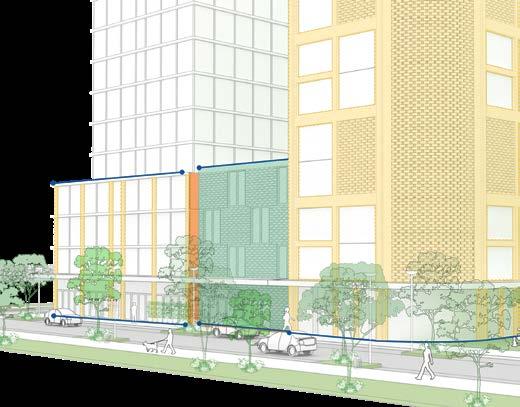
Fine grain frontages and buildings
Variety in architectural design for visual interest and character
Long podiums visually broken to create variety and ensure human scale
Articulation zone to provide depth for design of building façades
P1. Where large buildings are proposed, they are to have a contextual variety of architectural character to provide individual identity to residents.
P2. Reduce the scale of building mass through vertical or horizontal articulation and using depth in façades.
P3. Use articulation zones in podiums to reduce mass, provide outdoor space and greenery and create depth and shade.
P4. Strive for simplicity of and not complexity in articulation.
C1. Ensure for articulation of buildings into vertical bays and the integration of landscape to all elevation that are seen from public space.
C2. An articulation zone with a 1.2m depth should be included in the street wall to allow architectural form to develop. Outdoor space within this zone can be applied to all building uses for amenity, surveillance and to add depth to facades.
C3. Facades facing the street or public space should be articulated with depth, relief and shadow as in C2. A minimum relief of 150mm between the masonry finish and glazing face should be utilised to provide depth and shadow.
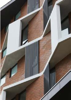
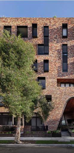
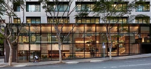
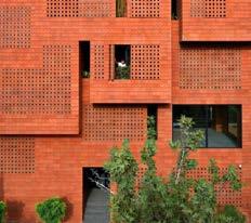
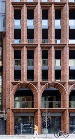
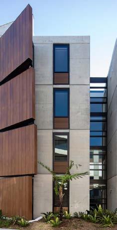
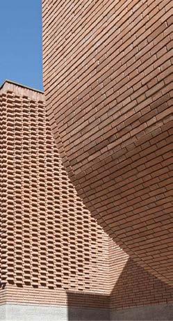
Buildings in our cities need to be comprised of low maintenance, robust and quality materials that will last the test of time. Canterbury Local Centre’s heritage buildings demonstrates the success of this approach and how it provides Canterbury with its own special character. The many heritage items and historic shopfronts within the Local Centre create the opportunity to reference the past and to knit new development into the built environment. These materials include face brick and masonry.
O1. To ensure high-quality materials and finishes seen in Canterbury’s heritage buildings is used throughout new development, with an emphasis on the ground floor, to enhance the pedestrian experience.
O2. To ensure material selection and finishes are robust, have longevity, are low maintenance and contribute to beautiful buildings.
O3. To ensure Canterbury’s heritage is reflected in the treatment of new development.
P1. Primarily use face brickwork, masonry and off form concrete.
P2. Have a higher ratio of solid to void in facades in response to heritage.
P3. Insert fine detailing through the use of timber, copper and metal.
P4. Create simplicity through the selection a common language of materials and finishes, rather than selecting many and creating visually complexity.
C1. Buildings must include durable single finish material finishes such as masonry, face brick and/or off form concrete. Painted cement render or similar painted finishes and Aluminium Composite Panel Cladding (e.g. Alucobond) must not be used. The use of glazing is not supported for awning construction or for parapet edges on rooftops.
C2. Elevate the pedestrian experience at street level through fine grained detailing using brickwork and provide details using copper, tiles and tactile surfaces.
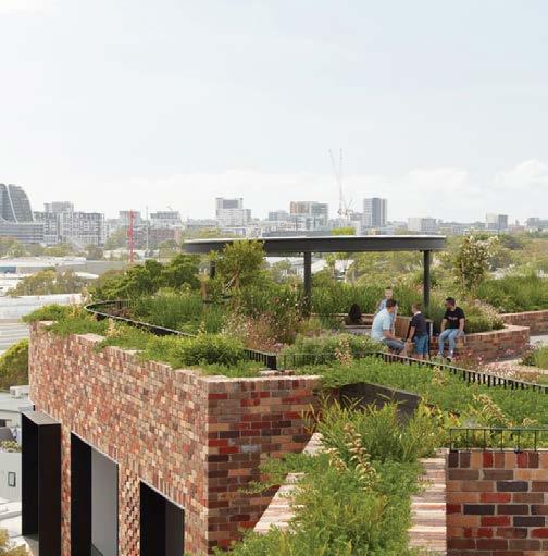
O1. Ensure that rooftops achieve good amenity standards for residents.
O2. Encourage the use of rooftops for passive recreation and communal uses.
O3. Design rooftops to minimise the urban heat island impacts by using landscaping species suitable for windy and dry conditions and by providing shade structures.
O4. Ensure rooftop open spaces are designed to promote the use of water and energy collected on site.
O5. Ensure balustrades around rooftop communal spaces are integrated into the design of the space and contributes to the overall appearance.
O6. Ensure harness anchor points are considered and integrated into the design where required for maintenance works to green roofs and walls.
P1. Include well designed shade structures constructed of low maintenance natural materials for shading to seating areas and for trees and landscape for protection from summer sun and UV.
P2. Design spaces that people want to linger in due to the provision of shade or winter sun, landscape and facilities for passive socialisation.
C1. Building rooftops that are designated communal open space areas must be designed to include:
(a) Fixed seating in areas with shade and solar access, where appropriate.
(b) Accessible toilet facilities.
(c) Structures for rain protection and sun shading.
(d) A BBQ/food preparation area with a sink that is universally accessible
(e) Watering systems for proposed landscaping, and
(f) Stormwater management and disposal.
C2. Any rooftop structures are to be included in the maximum height of building permitted for the site within CBLEP 2023. The height is to be shown in the Development Application drawings.
C3. Any proposed communal open space located on the building podium and/or rooftop is to:
(a) Be consolidated into a useable area with a minimum width of 6m and a minimum area of 36m².
(b) Be located so that solar access is provided for users of the open space.
(c) Be designed to a high quality and allow for landscaping and seating.
C4. Roof tops are to be structurally sound and have the capacity to support planting and adequate drainage.
C5. Communal open spaces must be designed to:
a) Accommodate both passive and active recreational uses, including clearly defined quiet or passive areas for relaxation and social interaction; and
b) Include designated children’s play spaces that incorporate age-appropriate features such as swings, play equipment, landscaped mounds, and other interactive elements.
The functionality, layout, and design quality of communal open spaces must be clearly demonstrated in the submitted architectural and landscape plans.
O1. Provide a range of housing types and sizes to support diverse households including single person families, multi-generational families, group households, students and seniors.
O2. Ensure for equitable access to new housing opportunities for culturally and socio-economically diverse groups.
O3. Encourage the design of buildings that are adaptable and flexible to accommodate residents’ changing housing needs over their lifetimes.
C1. The following dwelling mix is required for residential flat buildings and shop top housing developments containing 20 or more dwellings:
(a) Studio: between 5-10%.
(b) 1 bedroom: between 10-30%.
(c) 2 bedroom: between 40-75%.
(d) 3 or more bedroom: minimum 10%.
C2. The dwelling mix requirements may be altered only if the development serves the purpose of public housing or if the applicant represents a community housing or non-profit organisation.
C3. Within residential flat buildings, bedrooms should be located within apartments that have level access to adjoining communal space to provide accessibility to that space for disabled, elderly people and families with children.
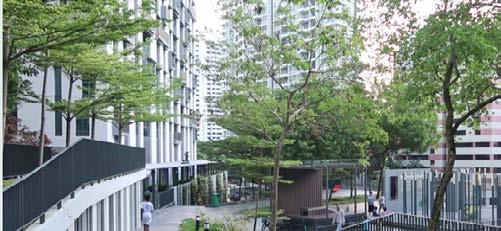
O1. Promote sustainable transport and limit vehicular movements by restricting private parking and facilitating increasing access to, and use of, communal modes of transport within the Local Centre.
O2. Require a lower minimum parking rate in the Local Centre ‘Core’ near the Canterbury Metro station, with a slightly higher minimum parking rate outside of the Local Centre ‘Core’ to minimise a reliance on private motor vehicle trips.
Principles
P1. Encourage basement vehicular parking instead of at-grade or above ground parking.
P2. Provide flexibility for the efficient use of car parking in development by allow off-site users to use car parking.
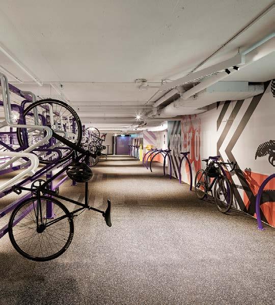
P3. Where provided, design above ground car parking so that it can be adapted to alternate uses over time.
P4. Consider the location of car park and service vehicle entrances and exits to ensure the amenity of public domain is maintained and improved where possible.
P5. To facilitate adaptation of car parking to other uses in the long term, above ground car parking is to remain as part of the common property and not part of, or attached to, individual strata units.
Controls
C1. All car parking within the Local Centre must be provided in accordance with the rates as specified in Table 8 and Figure 63. If a land use is not included in Table 8, the car parking rates in Chapter 2 Chapter 3.2 of the CBDCP 2023 will apply.
Refer to Chapter 3.2- Parking of the
Table 8: Car parking requirements for the Canterbury Local Centre 'core' and outside of 'core' areas.
C2. Parking for non-residential uses, and non-staff related parking can be considered collectively and be shared if parking is accessible to the public and the hours of use have different peak demand times.
C3. If the total Gross Floor Area (GFA) of retail premises exceeds 2,000m², a Transport Impact Assessment for the development proposed is to be prepared and submitted.
O1. To facilitate large floorplate uses underground, while maximising activation and permeability at street level.
Principles
P1. Uses permitted for underground floor space include uses that generally require large floor areas, including neighbourhood supermarkets, larger floorplate retail premises over 1000m² GFA, gym and entertainment facilities.
P2. Larger sites that can accommodate the above mentioned uses and demonstrate improved streetscape and public domain impacts.
P3. The underground uses should not go beyond the building footprint to ensure opportunities for deep soil planting and open space in setback areas are maintained.
P4. Entries to the underground floor space should have an appropriate, active, ground floor frontage.
C1. The basement levels used must have a minimum floor to ceiling height of 3.7 metres.
C2. The basement levels used must be the upper-most basement levels, closest to ground floor.
C3. The floor space is not used for the purposes of car parking.
C4. Does not result in the relocation of car parking at street level.
C5. Is located on a site with a minimum site area of no less than 3,000m².
C6. Any proposed or existing underground floor space is in addition to the maximum Floor Space Ratio for that site under the Canterbury-Bankstown Local Environmental Plan 2023 and any relevant applicable SEPPs. Any existing underground floor space on a site counts towards the maximum 1:1 underground floor space permitted.
The following sites have been identified as having a pivotal role in the realisation of the vision and objectives for the Canterbury Local Centre. The development of the key sites will be a catalyst for further development within the Local Centre and present an opportunity for precedent examples of design excellence, Connection to Country and the reflection of Canterbury's history and heritage through building form and materiality. The development on key sites will share a common language that is placed based.
To ensure for optimal outcomes for Canterbury and an efficient process for applicants, it is essential to engage with Council early in the Development Application process. Council will have an expectation to see detailed analysis of site, context and an understanding of the Aboriginal and European history of Canterbury.
To ensure for a ‘fine grained’ approach to key sites, Council encourages the subdivision of large sites into smaller lots that are contextual to site. If this cannot be achieved, then a variety of different buildings should be introduced of varying architectural character, scale and height to provide individual identity for residents and visitors.
O1. Ensure that development is unique to the character, climate and demographic of Canterbury Local Centre.
O2. Achieve Design Excellence, create inspirational key sites with high quality innovative architecture that are sustainably built, reference Canterbury’s history and heritage, offer community benefit, provide new publicly accessible and private spaces that contribute positively to Canterbury’s sense of place and its skyline.
O3. Ensure that the principles of Connecting to Country are enshrined and represented in these sites.
O4. Ensure development does not compromise or reduce solar access to parks.
O5. Integrate laneways, expand the public domain, improve pedestrian and cyclist permeability and connect to existing and new open space.
O6. Provide for a range of heights on key sites to create an interesting and diverse skyline.
O7. Ensure that the interface of sites activates the public domain and invites the public into new publicly accessible spaces.
O8. Ensure that podiums are articulated to appear as smaller parts to create a positive fine grained and exciting experiences at street level.
O9. Ensure street blocks present as a group of buildings and not as a single building.
O10. Ensure for a common language between buildings using materials that are long lasting and need little maintenance such as masonry, face brick and natural building materials generally.
In the event of any inconsistency between this section of this chapter and other parts of this DCP, these provisions prevail to the extent of any inconsistency.
C1. The design and delivery of key sites will take a Country centred approach in accordance with the guidelines and controls at Section 2.3 of this Chapter.
C2. An Aboriginal consultant shall be engaged at the outset of the site and context analysis and throughout the design process.
C3. Where appropriate, refer to section 3.3 for specifications for cycleways, laneways and arcades.
C4. Key sites should provide up to 25% tree canopy and up to 50% green cover. Canterbury Square shall provide a minimum of 40% tree canopy cover to beautify this space and provide shade.
C5. Key sites will reflect the masonry heritage character of the Canterbury Local Centre through the choice of materials and finishes in development. Face brickwork and masonry and natural materials shall be used at a higher solid to void ratio. Contemporary design is invited using a palette of face brickwork, off-form concrete with timber and copper detailing. Render, Alucobond, curtain walls and glazed awnings and balustrades are not supported.
C6. Building articulation is to minimise different materials and colours and aim for simplicity not complexity. A response to orientation should be implemented to provide for the articulation of each façade. This can be achieved by the western facade being more closed and shaded with vertical blades to control heat, while the northern facade has deep eaves and horizontal shading and is more open to the sun.
C7. To mitigate urban heat, permeable paving will be used in association with understorey planting with canopy trees. Water features including misting sprays, fountains and design elements that store water should be provided. Publicly accessible laneways will be shaded as will arcades.
C8. Building facades should show depth and shadow and exciting detailing as shown at 4.5 and 4.6 of this Chapter.


A street block in single ownership bounded by King, James, Searle and Princess Streets located adjacent to the Canterbury Park Racecourse and Canterbury Park. This block benefits from a 6m ‘lane way’ between the lots fronting King Street and Searle Street.
A green, leafy, cluster of medium rise residential apartments set in landscape, with a diversity of apartment typologies that have access to a network of generous open spaces connected throughout the site.
P1. Enhance amenity, privacy and local character with a 6m landscaped street setback to King Street, James Street and Princess Street that includes provision for deep soil planting and large trees.
P2. Provide a 3m front setback along Searle Street to create an intimate green character.
P3. Utilise the existing north-south ‘laneway’ to create pedestrian connections across the block.
P4. Maximise retention of trees on site and Create a rear green buffer across sites and green heart to enhance amenity and habitat.


Potential public domain enhancement along Searle Street
Pedestrian connections
Taller built form along King Street 3m street setback
6m landscaped street setback
Indicative Building Envelope
P5. Establish the tallest buildings along King Street to address the Racecourse, and transition to lower scale at the rear along Searle Street, providing a transition in building bulk to the senior citizen centre.
P7. Deliver public domain enhancement and connectivity improvements with the senior citizen centre along Searle Street.
The civic and vibrant heart of the Local Centre. These two sites address Jeffrey Street South and have a common boundary with a newly created Jeffrey Lane. This development will create a new 1,500sqm public plaza, Canterbury Square, that will activate the heart of the Local Centre and extend Pierson Lane to the northern edge of 61-17A Jeffrey Street. The existing Jeffrey Lane will be closed off. The Square will be reinforced by high quality buildings that will set a benchmark for design excellence within the Local Centre and be a public space to be enjoyed by the community.


Design Principles
P1. Deliver a high quality civic square of at least 1,500m2 of public open space to anchor the development as a new civic hub for the Local Centre that works in cooperation with the new civic high street, Robert Street. Provide a minimum of 2 hours solar access to 50% of the area of the square at the winter solstice on the 21st June.


Figure 66: KS2- 73-87

and 67-71A
P2. Extend Pierson Lane to the northern edge of 61-71A Jeffrey Street to replace the existing Jeffrey Lane. This will remove vehicle circulation from the northern edge of the square.
P3. Relocate the existing supermarket underground to maximise active uses at street level.
P4. Activate Canterbury Square on Jeffrey Street South and Pierson Lane, where possible with fine grain shopfronts.


P6. Mitigate urban heat gain in the design and material selection for the square. Use permeable paving, water features, misters and lush planting.
P7. Have a higher ratio of solid to void in building facades in response to Canterbury’s heritage character.
P8. Select materials and finishes that have longevity, minimal maintenance and are robust. Reinforce the heritage character in Canterbury using face brickwork and masonry.
P1. Ensure partnership with First Nations people in the planning and delivery of public open space.
P2. Minimum 40% canopy coverage across the site.
P3. Minimum 50% of the open space must have a minimum of 2 hours of continuous solar access.
P4. Minimum 50% of the site must be deep soil zone – ensure all deep soil zone are free draining and not covered, all paving within deep soil zone should be permeable.
P5. Include a variety of active and passive recreational activity options.
P6. Include a playground area of minimum 350m².
P7. Include an open lawn area of minimum 500m².
P8. Arrange the space to allow direct, clear sightlines from surrounding areas into and through the space as per CPTED design principles.
P9. Include public art as part of the design of the open space.
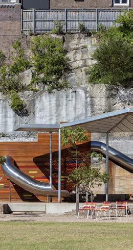
A triangulated block with address to Canterbury Road, Jeffrey Street and Pierson and Aldi Lane. This KS is comprised of two-story heritage shopfronts that provide character, scale and memory of Canterbury’s past.

Design Principles
P1. Sensitively retain and integrate the historic shopfronts on Canterbury Road.
P2. Enhance the public domain and activate the lane ways.
P3. Provide a podium design that is sympathetic to the historic facades in scale, materials and finishes.
P4. Provide upper storey setbacks above the historic shopfronts to provide separation between the old and the new buildings. Provide greenery in this triangular setback.
P5. Establish two separate towers, one along Jeffrey Street and the other on Aldi Lane and Canterbury Road to minimise bulk, optimise ventilation and solar access to the buildings and public space and preserve views to the sky from the public domain and from towers themselves.
P6. Create a through site link or an arcade within the building footprint from 173-175 Canterbury Road into Pierson lane.
This site is a catalyst for the Local Centre and for the southern side of Canterbury Road. The site is comprised of sixteen lots and is bounded by Canterbury Road, Tincombe and Minter Streets and is located to the north of the heritage listed Canterbury Hotel, a notable building in Canterbury’s urban fabric. The site will be highly visible from the public domain and will be the tallest building in the Local Centre. This site will provide a mix of uses in proximity to the new Metro.
P1. Create a quality outcome for the Local Centre and consider regional views by demonstrating design excellence across all levels of the development, reflecting on the Canterbury’s history and materiality, its Connection to Country and establishing a celebrated presence evident in the prominence of its tallest elements.
P2. Set the buildings back from the Tincombe Street and Canterbury Road intersection to retain views to the Canterbury Hotel along Canterbury Road from the north and south and provide public domain enhancement to all surrounding streets. Use face brick that is complementary to the Canterbury Hotel throughout the development.
P3. Locate the tallest buildings near the station and transition height towards the eastern residential area. Ensure appropriate separation is provided to reduce bulk and maximise solar access to neighbouring sites.
P4. Create a new pedestrian through site link connecting the signalised crossing of Canterbury Road through to Minter Street via a new civic plaza.
P5. Create a civic plaza of 500m² minimum. The courtyard will be activated by retail and commercial premises, provide seating, high quality landscaping, shade , solar access and integrate public art. It's entry points should be legible from the public domain and remain accessible to the public 24h/7. Final location and dimensions are subject to modeling carried out during the exhibition period.
P6. Activate Canterbury Road and Tincombe Streets and create a destination in the Local Centre by supporting a diverse commercial, food and retail offer. Large format retail uses such as supermarkets are to be below ground floor located at basement level to maximise ground level activation.


These sites are located directly south of the train line and are bounded by Canterbury Road, Close Street and future open space to the east. The vision for KS-5 is to create buildings that respond to the natural environment and reference connection to the Sugar Refinery heritage items further to the east along the Cooks River pathway.
Design Principles
P1. Provide a pedestrian through site link along the northern edge of the site from Canterbury Road to link to the future open space and to the Cooks River Pathway.
P2. Provide a sensitive interface with the residential strata building at 226 Canterbury Road that transitions and reduces bulk and ensures for solar access.
P3. Buildings should be designed so windows and balconies provide surveillance of the parkland.
P4. Have greater solid to void ratios in facades to reflect Canterbury’s heritage character.
P5. Provide active edges along Canterbury Road and active street frontage to the future open space.


P6. As building are visible from the open space and from Campsie Centre, particular consideration should be provided to the form and design as viewed from the wider context.
P7. Provide a minimum of 3m green interface setback along the boundary with adjacent sites.
P8. Access and service should be located along Close Street.
P9. Activate Canterbury with fine grain tenancies on the ground floor.
Indicative Building footprint
3m green interface setback with adjacent sites
Adjacent Strata Building
Vehicle access and servicing/loading
Active Frontages�
Active Edges
Fine grain shopfront on Canterbury Rd
Solar access
Proposed 4m wide pedestrian and cycle link
3m street setback
This triangular site establishes an architectural landmark at the northern gateway of Canterbury while retaining the heritage listed police station along Canterbury road and providing a softer interface to the residential area south and East to the site.
Design Principles
P1. Integrate the heritage item in the development by locating the primary building envelope along Church Street rather than Canterbury Road. This creates opportunities for landscaped courtyards framing the heritage building, enhancing and preserving its view.
P2. Provide upper storey setbacks and articulation to the tower and podium to address its prominent location at the northern gateway to the Local Centre and reduce visual bulk to the residential area to the east and the south.
P3. Deliver high quality landscape treatment that integrates the heritage item into the development and enhances its amenity.
P4. Provide a 3m planted buffer setback along the southern edge
P5. Retain and Integrate the existing historic shop at 154 Canterbury Road into the development. Together with the heritage item they create a cluster of historical buildings on the south-western corner of the site where a network of character filled courtyards and alleys leverages the unique historical built legacy of the precinct.
P6 Deliver high quality landscape treatment that connects the old and the new buildings together, emphasizing the historic nature of the site in the design, lighting and the choice of materials.
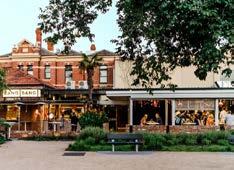

Landscaped courtyards
Indicative Building envelope
Heritage Item
Existing historic shop
HIgh quality landscape treatment
3m landscape buffer
Interface with low density residential area
Northern gateway to Canterbury Active Edges

Gateway tower
Vehicle access and servicing

This significant site is a key component to the vitality of the civic areas of the Local Centre and is located at the corner of Robert and Broughton Streets adjacent to the station. Robert Street is the primary civic street and works together with Jeffrey Street South and Square to form the Local Centre’s core. Taller slender building will act as landmarks within the core which will be read from inside and outside of the Local Centre.


P1. The site forms part of a civic street wall on the northern side of Robert Street.
P2. Activate the ground floor with fine grain shopfronts on both Robert and Broughton Street frontages and provide an engaging urban environment for visitors and residents.
P3. Provide a 3m street setback at the frontage to Robert Street to widen the street and establish well designed high amenity public domain to support the commercial activity of the shopfronts and the movement of pedestrians in the Local Centre.
P4. Locate vehicle access and services on the secondary frontage, Broughton Street, away from Robert Street and the corner.
P5. Create a place-based design that has been considered from all facades and responds to orientation with special attention given to the architectural treatment of the corner, which is visible from the station, to act as a cue in navigating to Robert Street.
P6. Create a slender, simply articulated tower design and 3 storey street wall to enhance solar exposure and amenity to Robert Street.

Key site boundary
Active Frontages with fine grain shopfront�
Active Edges
Vehicle access and servicing/loading
3m deep soil planting zone supporting mature tree growth
Landscaped courtyard
Landscaped podium and rooftop
3m street setback
Indicative Building envelope
Tallest building element
Special architecture treatment of prominent corner
Solar access to Robert Street
Proposed High Street
P7. Establish at a minimum, a 3m wide deep soil planting zone along the western boundary capable of supporting mature tree growth to interface with the R4 residential zone.
P8. Provide high quality landscape design to the ground floor and podium rooftop reflecting Connecting to Country principles, enhancing local amenity, establishing habitat, and supporting passive cooling of the environment.
P9. Provide a high quality communal rooftop that has planting that responds to climate and provides shade for users.
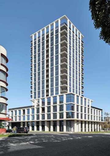

2m
6m
This mid-block site is at the heart of Robert Street and has the potential to set a benchmark for design quality for the Local Centre. This site works together with KS-7 to provide a civic street frontage activated by fine grained shopfronts. Uses may include hospitality, commercial and retail at street level with residential uses above to activates the Centre Core. The site will deliver a service lane on the eastern boundary to ensure the Robert Street frontage has optimal activation and pedestrian safety and that waste servicing will occur behind the development.
P1. Ground floor activation with fine grain shopfronts along Robert Street which turns the corner onto the service lane, Robert Lane, creates a destination and attractions to the new high street.
P2. A 3m street setback and public domain improvement delivers a high amenity pedestrian friendly environment supporting the vibrancy of the street.
P3. Establish at a minimum, a 3m wide deep soil planting zone along the western boundary capable of supporting mature tree growth to interface with the R4 residential zone.


P4. High quality materials and finishes reminiscent of Canterbury heritage to be utilised for the podium, retails shopfronts and public domain. Face brickwork and masonry is recommended.
P5. Slender built form and a 3 storey street wall enhances solar exposure and amenity to Robert Street, with a 3m upper-level setback along Robert Street and 2m upper-level setback along the new laneway.

Key site boundary
Active Frontages�
3m street setback
2m Upper level setback along the new lane way
9m wide access and
6m wide pdestrian anc
Vehicle access and servicing/loading
Vehicle access and servicing / loading to neighbouring site
3m deep soil planting zone supporting mature tree growth
Landscaped courtyard
Landscaped podium and rooftop
Indicative Building envelope
Tallest building element
Solar access to Robert Street
Proposed High Street
P6. A 9m wide two-way service lane will be delivered along the site's eastern boundary. It will service the development and ensure the Robert Street frontages remain dedicated to commercial activity with high amenity. In the future the lane will extend as a pedestrian lane up to John Street
P7. Provide high quality landscape design to the podium rooftop reflecting connection to country principles, enhancing local amenity, establishing habitat, and supporting passive cooling of the urban environment.
1-3 Close Street and 242258 Canterbury Road
Vision
To create a development with a sense of place that reflects the heritage of Canterbury Local Centre and provides an address and connection with the Cooks River.
Key Objectives
O1. Break down the scale of the development so it appears like several buildings.
O2. Integrate the development to its natural and historical context.
O3. Minimize the number of materials used in facade and rationalize the design.
O4. Establish a positive architectural gateway to the south of the precinct.
O5. Establish an engaging public realm interface to Canterbury Road and Close Street.
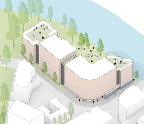
Green roof top to provide passive open space and views over the river for the residents
future development.
P1. Use materials that reflects Canterbury’s heritage and history and responds to the proximity of the Sugar House and the Canterbury Hotel on Canterbury Road. This includes face brick, stone and concrete.
P2. The facade along Close Street is to appear visually broken into three different buildings, each one in a different but complimentary face brick or masonry and separated from each other by a recessed vertical indentation. Each indentation’s length to depth ratio must range between 2:1 and 3:1. The total length of the two indentations must be equal to 15% or more of the total length of the Close Street facade.
P3. The facade along Canterbury Road is to appear visually broken into two buildings separated by one recessed vertical indentation of 1.5m depth minimum and a length to depth ratio ranging between 2:1 to 3:1.
P4. A portion of the development that is visually expressed as a building, (as opposed to an indentation) must be taller than the adjacent indentations by at least 1.5m so that the visual differentiation between the buildings is also reflected in the skyline of the development and fully perceived from the public domain.
P5. The development must provide opportunity for rooftop communal open space that takes advantage of its prime location along the Cooks River and Leslie Muir Reserve.
P6. The development must provide a generous double height internal public plaza at the Close Street intersection extending further into a pedestrian connection through to the Cooks River. The plaza should be designed with high quality material finishes and landscaping, and should be sleeved with active uses on the ground floor such as cafe, restaurant, corner shop or commercial premises.
P7. The development should provide commercial ground floor along Canterbury Road and close street to the extent of the B2 zone.
P8. The landscape design and the plant selection throughout the development should reflect and take cues from the Cooks River, its history, its natural landscape and its ecology.
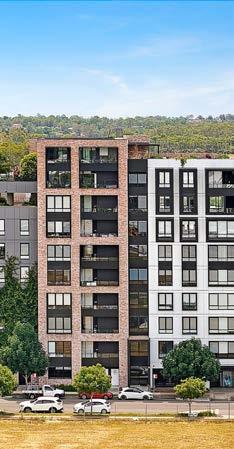
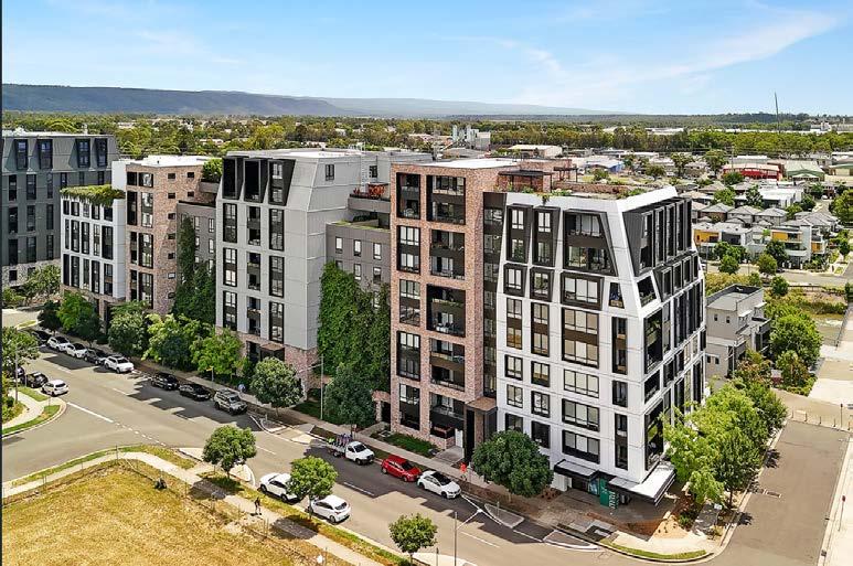
Architectural character refers to the style, design, and general arrangement of the exterior of a building and includes articulation, composition of building elements such as but not limited to fenestration, material use and details, building entrances, balconies, balustrades, awnings, planters, pergolas, boundary walls, fences.
Annual Exceedance Probability (AEP): The chance of a flood of a given or larger size occurring in any one year, usually expressed as a percentage. For example, if a peak flood discharge of 500m3/s has an AEP of 5%, it means that there is a 5% chance (that is a onein-twenty chance) of a 500m3/s or larger event occurring in any one year.
Articulation zone applies to a tall building and means that within the street frontage length of a podium, a 1 - 1.5m deep articulation zone is provided to allow architectural form to develop. Balconies for amenity and surveillance of the street form part of this articulation zone.
Building envelope means the space that is defined by the maximum building height, gross floor area, street, side and rear setbacks and upper storey setbacks.
Destination shade is where the shaded area is the focal point.
Dynamic content sign means a small format sign that has a digital, LCD, LED, plasma or other electronic display area capable of displaying animated, variable or multimedia content and requires a continual power supply for the display area to show content.
EV Distribution Board is a distribution board dedicated to EV charging that is capable of supplying not less than 50% of EV connections at full power at any one time during off-peak periods, to ensure impacts of maximum demand are minimised, and that increases to electrical feed sizes are not required. To deliver this, the distribution board will be complete with an EV Load
Management System and an active suitably sized connection to the main switchboard. The distribution board must provide adequate space for the future installation (post construction) of compact meters in or adjacent to the distribution board, to enable the body corporate to measure individual EV usage in the future.
EV Ready Connection Is a spare dedicated 32A circuit included in the EV Distribution Board to facilitate seamless future installation of cabling from an EV charger to the board, along with a circuit break-er to supply power to the circuit.
EV Load Management System is to be capable of:
⚬ Reading real time current and energy from the electric vehicle chargers under management
⚬ Determining, based on known installation parameters and real time data, the appropriate behaviour of each EV charger to minimise building peak power demand whilst ensuring electric vehicles connected are full recharged.
⚬ Scale to include additional chargers as they are added to the site over time.
Fine Grain is architectural character and includes massing, articulation, composition of building elements including material use and details. These include building entrances, fenestration, signage, balconies, balustrades, awnings and planters at street and lane level.
Floorplate refers to the total area occupied by a single floor of a building, measured from the outer edges of the external walls. It defines the building’s footprint at each level and influences factors such as structural efficiency, spatial layout, access to natural light, and overall building massing.
Front setback means a setback from a street boundary.
Green roofs (including green awnings) are roof surfaces that are partially or fully covered with vegetation are known as green roofs (or green awnings). They have a series of layers including a vegetated layer, a growing medium, and a waterproof membrane.
Incidental shade is shade experienced when passing by or through.
Isolated site is a site that has limitations on its future potential development because of its size and shape, proximity to other development and its ability to be consolidated with other properties for development purposes.
Large developments are developments with a minimum frontage of 45m of greater.
Large food waste generating businesses are premises that produce ≥660L/week of red bin capacity.
Major drainage systems: “Overland” drainage routes, which can include roads and recreational are-as. Minor drainage systems refer to all gutters, pipes, culverts, open channels, natural creeks and other storm water infrastructure.
Maximum External Solar Reflectance is the maximum allowable percentage of solar reflectance for the external face of a Reflective Surface. The percentage of solar reflectance is to be measured at a normal angle of incidence
Non-reflective surfaces are those surfaces that diffusely reflect light and heat and for this DCP are defined as those surfaces that have a specular normal reflection of less than 5%.
Normal operations refers to all building energy requirements other than the provision of standby power generations.
Open space is hard surfaced public space within a square, courtyard or plaza as well as open parkland with landscape and play areas.
Pedestrian lanes are non-trafficable by vehicles and cyclists and are for pedestrians only. These lanes are narrower and are open to the sky but may in part be covered by awnings.
Pedestrian links are non-trafficable by vehicles and are for pedestrians only. These lanes are narrower and are predominantly open to the sky but may in part be covered by awnings or buildings.
Podium means the base of a taller building that is built close to or along the site boundary or boundaries.
Probable maximum flood (PMF): The largest flood that could conceivably occur at a particular location, usually estimated from probable maximum
Public domain are the peripheral streets and open spaces surrounding or adjoining the site.
Publicly accessible space is located on a private site and invites the public into through site links and green spaces.
Reflective Surface Ratio (RSR) is the ratio of reflective to nonreflective external surface on any given façade.
Reflective surfaces are those surfaces that directly reflect light and heat and for this DCP are defined as those surfaces that have a specular normal reflection of greater than 5% and includes glazing, glass-faced spandrel panel, some metal finishes and high gloss finishes.
Reinforced corner is where the building corner that must address both street frontages, define and reinforce the street edge through massing and façade orientation and ties together the different street frontages and podiums. Reinforced corners may exceed the maximum podium height of connected street frontages.
Service lanes prioritise vehicles over pedestrians between 10pm7am. At other times during the day.
Shared EV Connection provides a minimum Level 2 40A fast charger and power supply to a designated car parking space, which is connected to an EV Distribution Board.
Shared lanes give pedestrians priority over vehicles and have footpaths that are level with lanes. Service vehicles use these lanes between 8pm-7am.
Solar heat reflectance is the measure of a material’s ability to reflect solar radiation. A 0% solar heat reflectance means no solar heat radiation is reflected and 100% solar heat reflectance means that all of the incident solar heat radiation is reflected. In general, lighter coloured surfaces and reflective surfaces such as metals will have typically higher solar heat reflectance, with dark coloured surfaces or dull surfaces will typically have lower solar heat reflectance. External solar heat reflectance measured at the surface normal (90 degrees) is used in these controls
Solar Reflectance Index (SRI) is a composite measure of a materials ability to reflect solar radiation (solar reflectance) and emit heat which has been absorbed by the material. For example, standard black paint has an SRI value of 5 and a standard white paint has an SRI value of 100. The lower the SRI value of a material, the more heat is absorbed and the hotter it will get.
Solar transmittance is the percentage of solar radiation which can pass through a material. Opaque surfaces such as concrete will have 0% solar transmittance, dark or reflective glass may have
less than 10%, whilst transparent surfaces such as clear glass may allow 80 to 90% solar transmittance.
Street frontage length is the length of a podium or street wall before a lane, link, entry lobby or similar is provided.
Street wall storey height is the storey height of the building or podium. It is what defines streets, spaces and laneways.
Tall buildings are buildings that are over 50m in height.
Through-site links provide internal pedestrian and cycling connections within a building, designed to enhance accessibility and support active transport. These links should be lined with fine-grained shop fronts to activate edges and create a vibrant, engaging public interface.
Upper storey setback means the setback from a site boundary for the part of the building located above the street wall or podium.
Figure 43. A four storey street wall defines the street edge, Breese by Breathe architects, photo by Tom Ross.
Figure 44. A street wall elevation is to be prepared to demonstrate how the proposed development fits with the existing neighbouring buildings in the block
Figure 50. Building separation with high amenities in public domain
Figure 51. Floorplate controls for towers seek to ensure good functionality, circulation, amenity, solar access and maximise views to the sky 69
Figure 52. Natura, Macquarie Park, NSW, Architectus. 70
Figure 53. Eve Street, Erskineville 71
Figure 54. Active street frontages and edges map 74
Figure 55. Awnings map 75
Figure 56. Design guidance on building façades to ensure visual diversity, articulation and fine grain 76
Figure 57. Brick wall interfacing open space 77
Figure 58. Glyde Bautovich Via Apartments 77
Figure 59. Examples of high quality materials and finishes for building envelopes 79
Figure 60. Rooftop communal open space, Arkadia, DKO by Tom Ross 81
Figure 61. Dwelling mix (Source: Designing child friendly- high density neighbourhoods, pp63) 83
Figure 62. Riverside Quay, Southbank, VIC, Architectus 84
Figure 63. Canterbury Local Centre core and noncore car parking areas 86
Figure 64. Key Sites Map 91
Figure 65. KS1- 1 59A King Street 186-206 Canterbury 92
Figure 66. KS2- 73-87 Jeffrey Street and 67-71A Jeffrey Street 93
Figure 67. Harold Park, Glebe, NSW 94
Figure 68. KS3- 153-189 Canterbury Road 95
Figure 69. KS4- 186-206 Canterbury Road 96
Figure 70. KS5- 214-224 and 2-8 Close Street 97
Figure 71. KS6- 146-150 Canterbury Road 98
Figure 72. Adaptive reuse by 6 degree architects, Bang Bang, Elsternwick 98
Figure 73. KS7- 17-23 Robert Street and 13 Broughton Street 99
Figure 74. Montague Square, by element 5, VIC Melbourne 100
Figure 75. KS8- 9-15 Robert Street 101
Figure 76. Axonometric view of 1-13 Close Street and 242-258 Canterbury Road indicative massing of potential future development 102
Figure 77. Building articulationbulk and massing 103
Figure 78. Building articulationbulk and massing (Source: Sheffield Circuit, Penrith) 104
Figure 79. Built form controlsHeights, street wall and setbacks.
Table 01. Legend explanation of Publicly accessible spaces map of Canterbury 34
Table 02. Indicative Minimum clearance of streetscape elements 43
Table 03. Minimum tree canopy cover for private land 44
Table 04. Controls 52
Table 05. Minimum floor-to-floor heights
Table 07. Active street frontage design guidance
Table 08. Car parking requirements for the Canterbury Local Centre 'core' and outside of 'core' areas