
Document Title: Function Group: Information Type: Date: Engine, description 200 Service Information 2014/4/6 0
Profile: CEX, ECR48C [GB]
Go back to Index Page
Engine, description
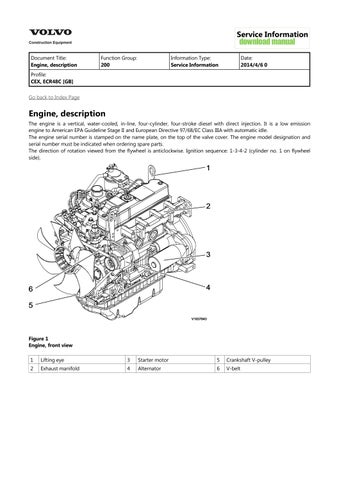
The engine is a vertical, water-cooled, in-line, four-cylinder, four-stroke diesel with direct injection. It is a low emission engine to American EPA Guideline Stage II and European Directive 97/68/EC Class IIIA with automatic idle.
The engine serial number is stamped on the name plate, on the top of the valve cover. The engine model designation and serial number must be indicated when ordering spare parts.
The direction of rotation viewed from the flywheel is anticlockwise. Ignition sequence: 1-3-4-2 (cylinder no. 1 on flywheel side).

1
Engine, front view 1 Lifting eye

Document Title: Function Group: Information Type: Date: Engine, description 200 Service Information 2014/4/6 0
Profile: CEX, ECR48C [GB]
Go back to Index Page
Engine, description
The engine is a vertical, water-cooled, in-line, four-cylinder, four-stroke diesel with direct injection. It is a low emission engine to American EPA Guideline Stage interim Tier IV and European Directive 97/68/EC Class IIIA with automatic idle. The engine serial number is stamped on the name plate, on the top of the valve cover. The engine model designation and serial number must be indicated when ordering spare parts. The direction of rotation viewed from the flywheel is anticlockwise. Ignition sequence: 1-3-4-2 (cylinder no. 1 on flywheel side).
1
Engine, front view
1 Lifting eye

Document Title: Function Group: Information Type: Date: Engine, removing 210 Service Information 2014/4/6 0
Profile: CEX, ECR48C [GB]
Engine, removing
Op nbr 210-070
Hoist or crane
Lifting device

WARNING
The work involves handling heavy components - failure to stay alert may result in severe crushing injuries.
1. Place the machine in service position 1. See 091 Service position 1

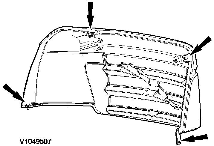
Figure 3
Rear cover, remove
5. Remove right-hand side panel.
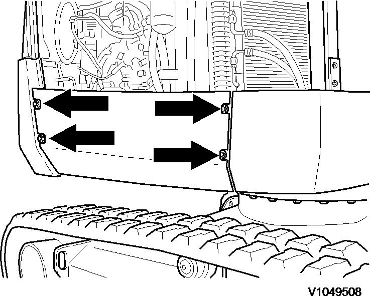
4
Right-hand side panel, remove
6. Remove silencer with tailpipe. See 252 Silencer, removing
WARNING
Open the radiator cap carefully if the engine is warm. High pressure in the radiator may cause hot coolant to jet out.
WARNING
Risk of scalding and burns. The coolant may be hot.
7. Detach and remove radiator cap (1) on radiator.
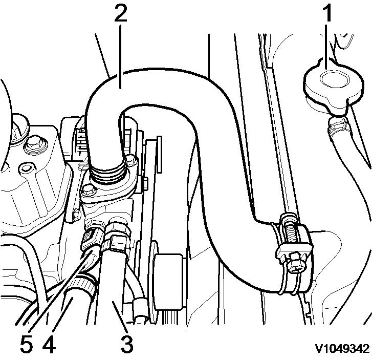
2. 3. 4. 5. Radiator cap
Upper radiator hose
Feed
Return
Engine temperature sensor
8. Provide a suitable catchment container for the coolant.
6
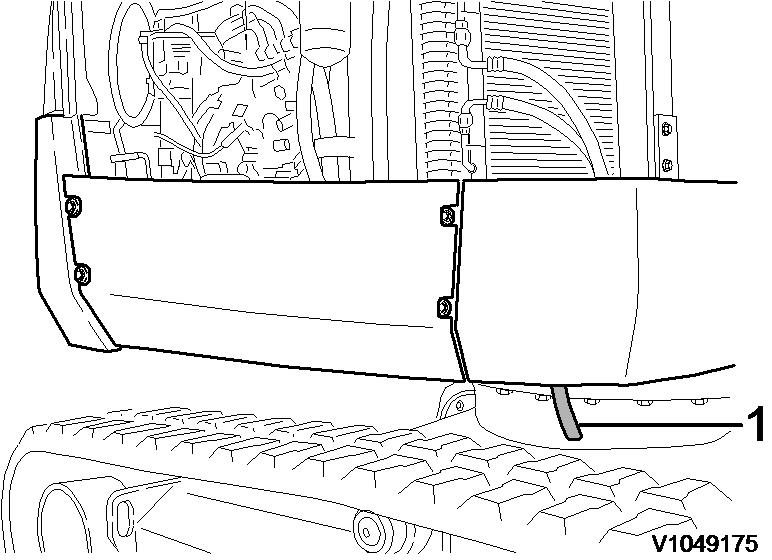
Position, drain valve
1. Drain valve
9. Open the drain valve (1) and drain all coolant into the container.
NOTICE
Cooling system conditioners must be disposed of in accordance with environmental regulations.
NOTICE
Do the work in an environmentally safe manner.

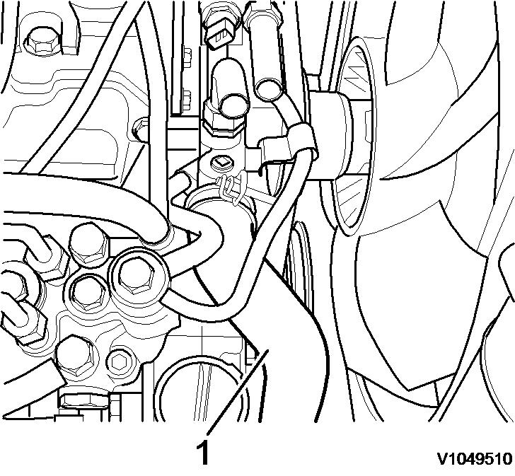
Figure 7
Position of drain plug
1. Drain plug
10. Remove hoses (3, 4) for cab heating on the engine.
NOTICE
When a hose has been disconnected, plug both the hose and the connection immediately. The hoses should be marked for correct connection.
Figure 8 Hoses, remove
Radiator cap Upper radiator hose Feed Return Engine temperature sensor
11. Remove the expansion tank from the bracket and drain the fluid into the catch basin.
12. Close the drain valve and screw on the radiator cap.
13. Remove the hose clamp on the upper radiator hose (2) and pull off the hose.
14. Remove the hose clamp on the lower radiator hose (1) and pull off the hose.
9
Radiator hose, remove 1. Lower cooler hose
15. Remove the fixing bolts (1) from the fan grille (2) and remove the fan grille.
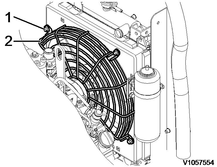


12
Fuel prefilter fixing bolt
18. Disconnect the electrical connection from the air filter sensor (1) and lay the connecting cable aside.
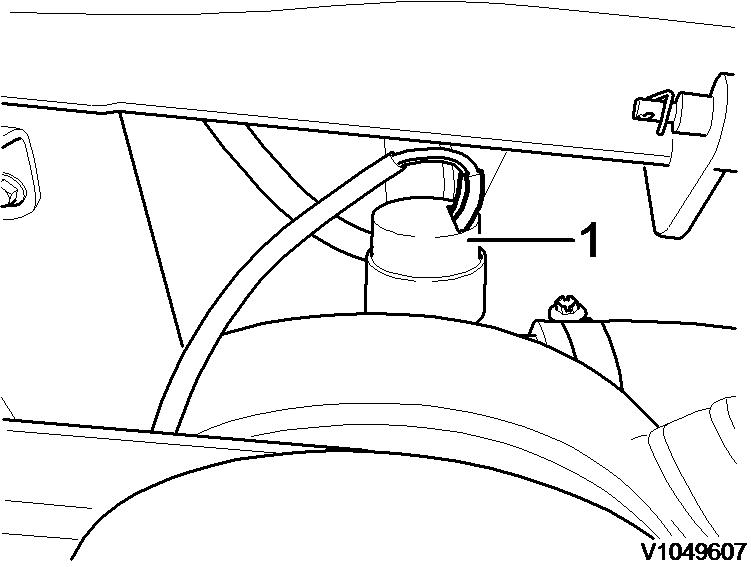
Figure 13
Air filter, remove connections
1. Air cleaner sensor
19. Detach the hose clamp (2) at the intake air hose (3) and pull off the intake air hose (3).
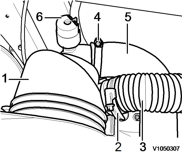
14
Air filter casing with hose connections
20. Detach the hose clamp (4) at the engine intake air hose (5) and pull off the engine intake air hose (5).
21. Remove the air filter holder fixing bolts and remove holder together with air filter casing.

15
Air filter holder fixing bolts
22. Remove accelerator cable on engine.
16
Remove accelerator cable
23. Disconnect the plug connection (5) at the fuel feed pump.

Figure 17
Fuel feed pump 1. 2. 3. 4. 5. 6. Output (OUT)
Fuel feed pump
Retaining screw
Input (IN)
Plug connection
Plug connection, automatic idle control - LS pressure switch
24. Disconnect the plug connection (6) for automatic idle control (option) at LS pressure switch.
25. Disconnect the plug connection (3) for automatic idle control (option).
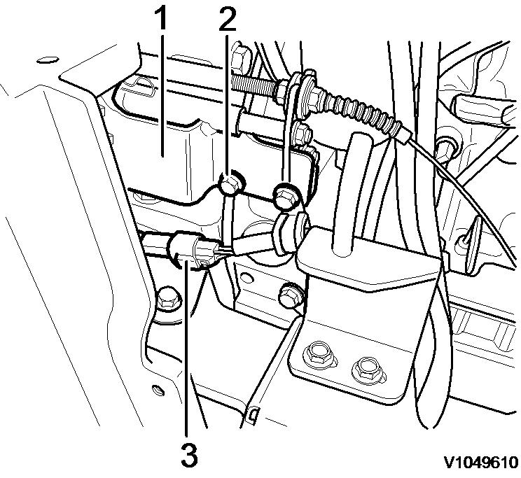
Figure 18 Automatic idle control, remove 1. 2. 3. Holder with magnet
Attaching screws
Plug connection
26. Remove fixing bolts (2) at the holder, and lay aside holder and magnets (1) for automatic idle control (option).
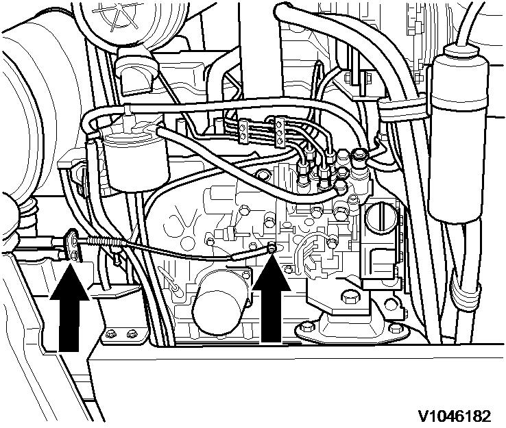
27. Remove hose lines at the fuel prefilter (1).
NOTICE
When a hose has been disconnected, plug both the hose and the connection immediately. The hoses should be marked for correct connection.

Figure 19
Fuel lines, disconnect
Fuel pre-filter Fuel filter
28. Remove hose lines at the fuel filter (2).
NOTICE
When a hose has been disconnected, plug both the hose and the connection immediately. The hoses should be marked for correct connection.
29. Loosen and unscrew the pump mounting bolts.

Figure 20
Fixing bolts, remove
30. Pull the pump towards the back and secure against falling.
31. Disconnect the main power supply (terminal 87) from the battery to the starter.
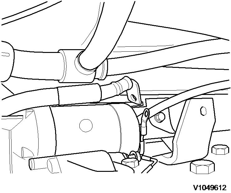
21
Main power supply to starter, disconnect
32. Remove retaining bolts (1) at engine mount.
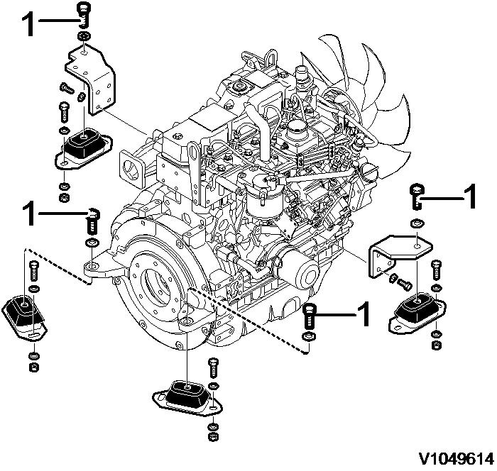
Figure 22
Retaining bolts at engine mount, remove 1. Retaining bolts
33. Disconnect plug connections to frame wiring loom and engine shut-off.

Plug connections, disconnect
34. Remove fixing clamps on wiring harness.
35. Attach lifting gear to engine lifting eyes.
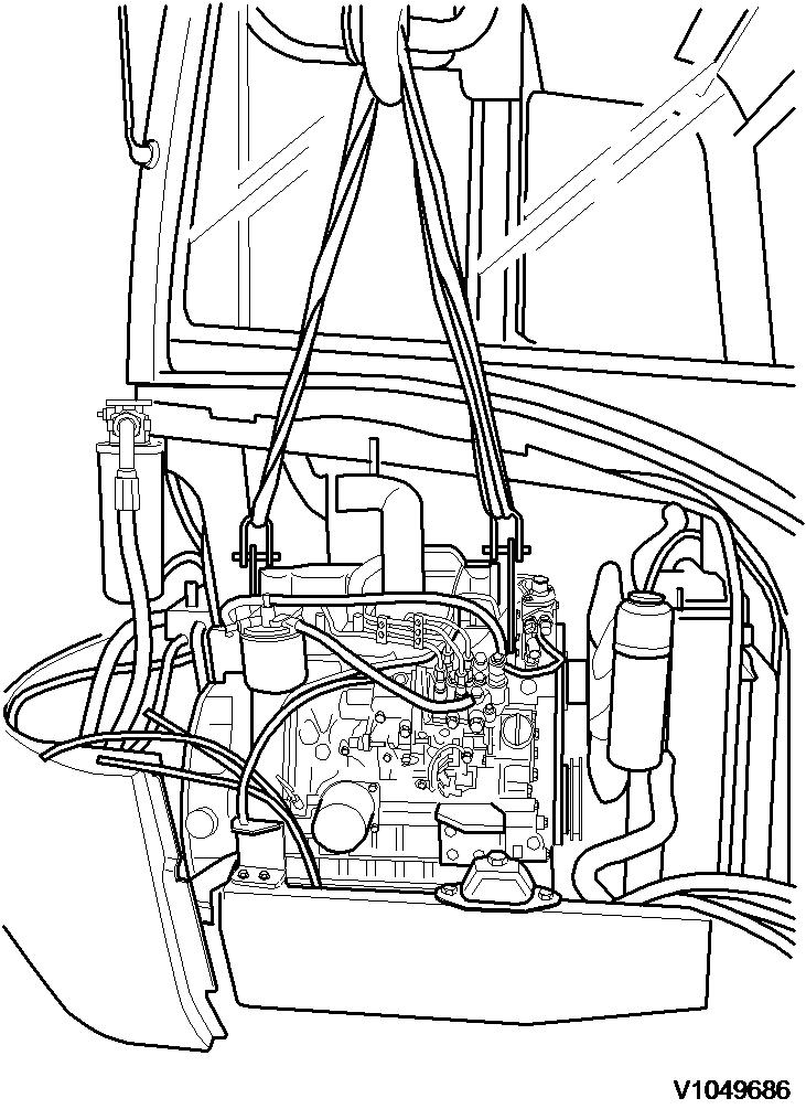
Figure 24 Lifting gear, attach WARNING
Risk of personal injury. Very heavy object.
36. Slowly lift out the engine and deposit on a suitable support.
Document Title: Function Group: Information Type: Date: Engine, installing 210 Service Information 2014/4/6 0
Profile: CEX, ECR48C [GB]
Engine, installing
Op nbr 210-072
Hoist or crane
Lifting device
WARNING
The work involves handling heavy components - failure to stay alert may result in severe crushing injuries.
1. Attach the engine to suitable lifting gear.
2. Slowly lower the engine into the engine bay and position on the engine mounts.
NOTICE
Make sure that no hoses or cables are trapped.
3. Screw in retaining bolts (1) on engine mounts and tighten with a torque wrench. See 030 Engine, tighten torques
Retaining bolts at engine mount, install
1. Retaining bolts
4. Remove the lifting gear.
5. Connect plug connections to frame wiring loom and engine shut-off.
3
Plug connections, connect
6. Position the fan grille and fit the fixing bolts.
Figure 4
Fan grille, installing
1. 2. Retaining screw Fan grid
7. Install fixing clamps on wiring harness.
8. Connect the main power supply from the battery to the starter.
5
Main power supply to starter, connect
9. Insert pump splined shaft into clutch carrier plate.

6
Hydraulic pump, install
10. Screw in the fixing bolts and tighten.
7
Fixing bolts, screw in
11. Install air filter holder with air filter, and insert fixing bolts.
8
Air filter holder with air filter, install
12. Connect the engine intake air hose (5) and fit hose clamp (4).
Figure 9
Air filter casing with connections 1. 2. 3. 4. 5. 6. Air cleaner casing Hose clamp
Intake air hose
Hose clamp
Air intake hose, engine
Air cleaner sensor
13. Connect the intake air hose (3) and fit hose clamp (2).
14. Connect the electrical connection for the air filter sensor (1).
Figure 10
Connections, install

Suggest:
If the above button click is invalid.
Please download this document first, and then click the above link to download the complete manual.
Thank you so much for reading
1. Air cleaner sensor
15. Mount the fuel prefilter to the air filter holder.
11
Fuel prefilter, install
16. Install the hose lines at the fuel prefilter (1). NOTE!
Note feed and return flows!
12 Hoses, install
17. Install hose lines at the fuel filter (2). NOTE!
Note feed and return flows!
18. Install holder with magnet (1) for automatic idle control (option).