
Service Information
download manual
Document Title: Function Group: Information Type: Date:
Engine, description 200 Service Information 2014/8/26
Profile:
EXC, EC240B FX [GB]
Go back to Index Page
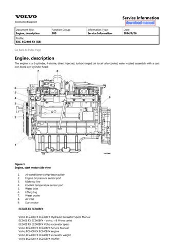
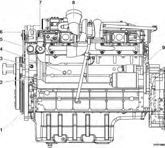
Engine, description
The engine is a 6-cylinder, 4-stroke, direct injected, turbocharged, air to air aftercooled, water cooled assembly with a cast iron block and cylinder head.
Air conditioner compressor pulley
Engine oil pressure sensor port
Make up line
Coolant temperature sensor port
Water inlet
Lifting lug
Water outlet
Air inlet
Start motor
EC240B FX EC240BFX
Volvo EC240B FX EC240BFX Hydraulic Excavator Specs Manual
EC240B FX EC240BFX - Volvo, – B Prime series
EC240B FX EC240BFX Volvo excavator specs
Volvo EC240B FX EC240BFX Service Manual
Volvo EC240B FX EC240BFX engine
Volvo EC240B FX EC240BFX excavator weight
Volvo EC240B FX EC240BFX muffler

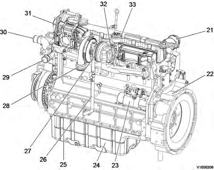
Fuel return line Air heater
Coolant preheater port
Coolant filter supply Fuel suction line

Water inlet Return from heater Engine oil filler Supply to heater

Alternator From charge air cooler To charge air cooler Oil drain valve
Document Title: Function Group: Information Type: Date:
Engine, description 200 Service Information 2014/8/26
Profile:
EXC, EC240B FX [GB]
Go back to Index Page
Engine, description
D7E -Tier 3 / Tier 3 base tier 2
The D7E configuration is a four stroke, straight six cylinder, turbocharged, direct injected diesel engine with charge air cooling and wet, replaceable cylinder liners.
The D7E engine uses a Common Rail Fuel System controlled by the engine electronic control (E-ECU) software.
Electronically controlled IEGR (Internal Exhaust Gas Recirculation) reduces NO formation and lowers emissions without the need for exhaust after treatment (Only applied Tier 3 engine)
Volvo's latest engine management system, EMS 2 is used to control all engine electronic functions. The cylinders are numbered consecutively beginning at the flywheel end. Engine rotational direction is counterclockwise as seen from the flywheel end.

Document Title: Function Group:
EXC, EC240B FX [GB]
Component locations

Component position, engine D7E. The following figures show the position of a number of components on engine D7E. Figure 1
2 Component locations, flywheel side
21 Crankcase bleeding valve
22 Flywheel housing
Air outlet (to charge air cooler)
Coolant inlet 23 Starter motor
Coolant outlet 24 Oil pan
25 Drain plug
26 Oil return line from turbocharger
Air inlet (from charge air cooler)
Exhaust manifold
Cylinder rocker arm cover 27 Turbocharger
Document Title: Function Group: Information Type: Date:
Engine characteristic curve 210 Service Information 2014/8/26
Profile:
EXC, EC240B FX [GB]
Engine characteristic curve
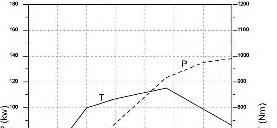
1
Engine, characteristic curve
A be (g/kW/h) : Fuel consumption
B T (N m) : Torque
C rpm : Engine speed
D P (kW) : Power
Document Title: Function Group: Information Type: Date: Basic check, Engine 210 Service Information 2014/8/26
Profile:
EXC, EC240B FX [GB]
Basic check, Engine
NOTE!
Certain tests and checks are performed with unlocked safety locking lever. Make sure that the machine cannot operate unexpectedly when the safety locking lever is unlocked.
Purpose of the basic check
The purpose of the basic check is to provide fast and accurate information about the general condition of the engine.
The basic check should be performed and evaluated according to instructions in the PC-tool VCADS Pro.
Tests included in the basic check
The basic check which is divided into the following tests should be performed after reading out error codes and checking parameters
Tests:
Cylinder compression, test
The purpose of the test is to show if any cylinder has a deviating compression pressure. The test replaces the old pressure check method but does not give any absolute values.
Cylinder balancing, test
The purpose of the test is to show if there is any deviation in the fuel injection to a cylinder.
Feed pressure, test
The purpose of the test is to check that the feed pressure is as per specification.
Sensor, test
The purpose of the test is to check the function of all sensors.
Document Title: Function Group: Information Type: Date:
Troubleshooting 210 Service Information 2014/8/26
Profile:
EXC, EC240B FX [GB]
Troubleshooting
General about troubleshooting
When a malfunction is suspected or has been confirmed, it is important to identify the cause as soon as possible. The starting point for all troubleshooting is that there is some type of trouble symptom or malfunction. Malfunctions can be indicated by:
generation of error codes detection of a malfunction symptom.
Troubleshooting work
The first step in troubleshooting is to gather information from the operator concerning the malfunction symptoms, see Electrical and information system, Collection of basic data. Then, attempt to pin-point the cause by checking in a certain order, for more information, see Electrical and information system, troubleshooting strategy. The different checking steps are:
Check error codes
Check parameters
Perform basic check
Troubleshooting information
The following is included in Electrical and information system and is used when troubleshooting:
Troubleshooting strategy
Describes troubleshooting work, step by step.
Troubleshooting, assistive devices
Brief summary of the assistive devices that are available for troubleshooting.
Functional checks and tests, VCADS Pro
Brief description of VCADS Pro. For a detailed description, see VCADS Pro User’s Manual.
Error code information
Contains information regarding error code design, lists of all error codes and error code information about each error code.
Components, troubleshooting and specifications
Contains methods and measuring values for troubleshooting of components. Also includes wiring diagrams and certain specifications.
Parameters
Incorrectly set parameters may cause malfunction symptoms. The parameter list includes all limit and command values for parameters.
Control units, functional description
Describes the functions of the control units, inputs and outputs as well as communication between the various control units.
Control units, active and passive measuring
Contains measuring values for active and passive measuring of the ECUs.
Software functions
Describes the pre-requisite conditions for the control and monitoring functions that are performed by the software in the ECUs.
Document Title: Function Group: Information Type: Date:
Cylinder head, description 211 Service Information 2014/8/26
Profile:
EXC, EC240B FX [GB]
Cylinder head, description
The cylinder head is made of grey cast iron and is common for all cylinders. The induction air enters vertically (A) and the exhausts leave horizontally (B). Inlets and exhaust outlets are located on the same side of the cylinder block. Inlet and exhaust valve size is increased to optimize the gas exchange and combustion process. Valve guides are replaceable. Coolant flow in the cylinder head is modified to accommodate an outlet controlled cooling system.
On order for the engine to fulfill governing emission standards, there are 3 cylinder head gaskets of different thicknesses between the cylinder head and the piston.
Document Title: Function Group: Information Type: Date:
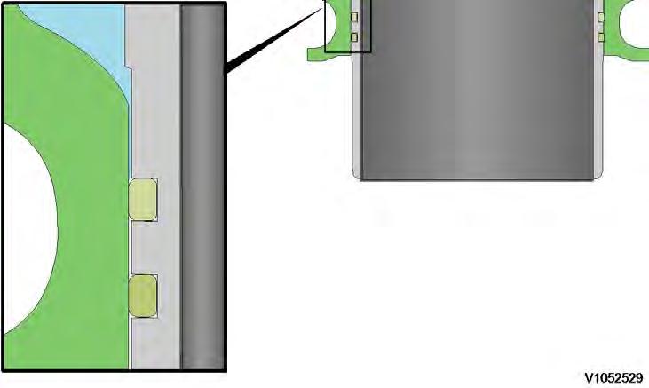
Cylinder head gasket, description 211 Service Information 2014/8/26
Profile:
EXC, EC240B FX [GB]
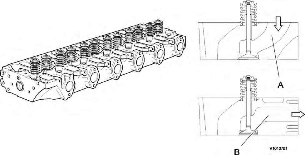
Cylinder head gasket, description
The cylinder head gasket is a multi layered gasket with 1, 2 or 3 identification holes to indicate three different thicknesses available. Selection of the proper thickness of gasket is determined by the measurement of piston projection above the cylinder block sealing surface. Recalibration for the correct gasket thickness would be required if new pistons or a new cylinder block were installed.
1
Document Title: Function Group: Information Type: Date:
Cylinder liner, description 213 Service Information 2014/8/26
Profile:
EXC, EC240B FX [GB]
Cylinder liner, description
The engine has a cylinder block with wet (replaceable) cylinder liners. The bottom part of the liner is sealed against the cylinder block with two O-rings positioned in grooves machined into the lower end of the liner. The upper part of the cylinder liner is sealed by the cylinder head gasket and the pressure created by the cylinder head clamping force against liner protrusion.

Document Title: Function Group: Information Type: Date:
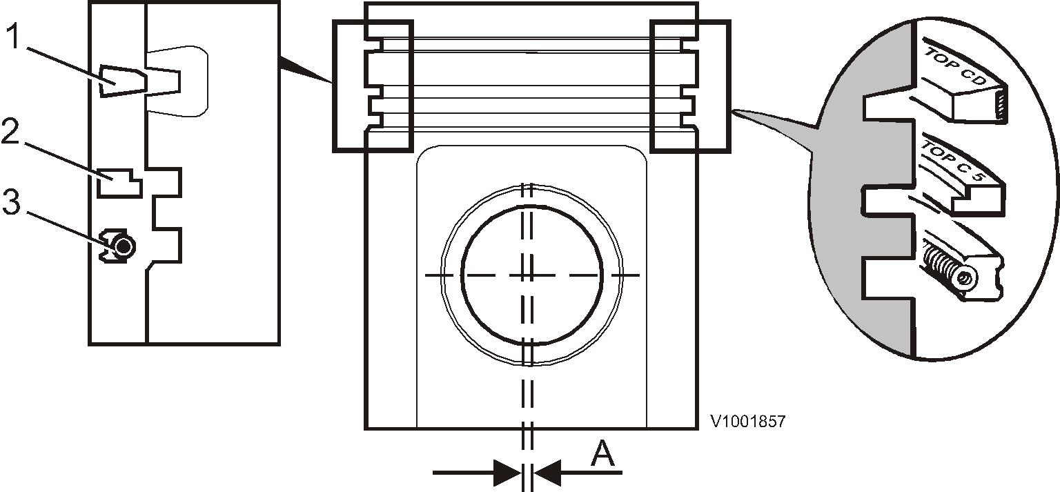
Pistons, description 213 Service Information 2014/8/26
Profile:
EXC, EC240B FX [GB]
Pistons, description
The pistons of the engine are made of special alloy aluminium.
The top of the piston has a combustion cavity and a flywheel symbol to indicate the correct piston orientation.
Piston cooling is by oil spray to the inside of the piston from nozzles located in the main bearing pedestals.
The pistons are provided with three piston rings, two compression rings and one oil control ring. The first or top compression ring has a cast iron carrier. The cross-section area for the second compression ring is tapered The third ring is an oil ring with a bevelled edge.
When installing the piston rings, the marking TOP by the opening in the rings must be face up.
Document Title: Function Group: Information Type: Date: Piston rings, description 213 Service Information 2014/8/26
Profile:
EXC, EC240B FX [GB]
Piston rings, description
Each piston is equipped with two compression rings and one oil ring. The uppermost compression ring is of the "Keystone" type (dual trapezoid-formed cross section). Compressions rings should be placed with the text facing upwards. The oil ring is equipped with two scraping edges, which are pressed against the cylinder wall using the spring tension in the ring and an expander spring placed on the inside of the ring. The oil ring can be placed on either side but should be placed with expander spring and oil ring openings 180° from one another.
Document Title: Function Group: Information Type: Date: Piston cooling 213 Service Information 2014/8/26
Profile: EXC, EC240B FX [GB]
Piston cooling

1
Piston cooling
The piston is cooled by spraying lube oil against the inside of the piston top.
The 2-hole piston cooling nozzles made of plastic are fitted in the main bearing pedestals.
Document Title: Function Group: Information Type: Date:
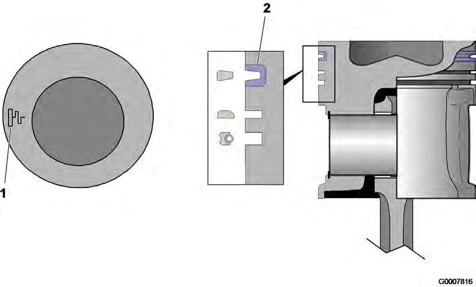
Valves, description 214 Service Information 2014/8/26
Profile:
EXC, EC240B FX [GB]
Valves, description
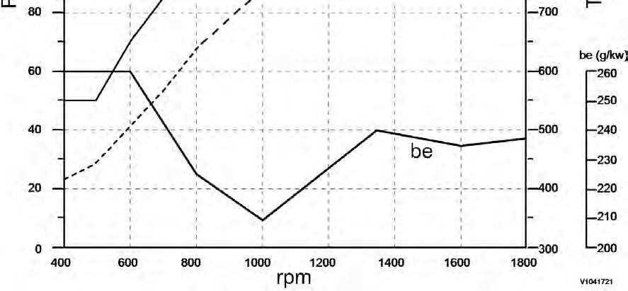
The engines are equipped with one inlet and one exhaust valve per cylinder.
At the upper end of the valve guide, there is an O-ring seal (A) against the valve spindle to prevent major oil consumption and to reduce the amount of hydrocarbons in the exhausts.
The valves are rotated by the eccentric action of the rocker arms.
The new compressed tapered shape enables the valves to turn easily despite loading.
Rocker arm lubrication is part of the engine force-feed lubrication system. The oil is supplied via the tappets and push rods. If the valve guides are replaced, they are obtained in another version (B) to facilitate installation.
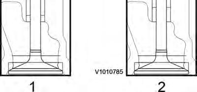
Figure 1 shows a valve guide installed in production and figure 2 shows a replacement guide.

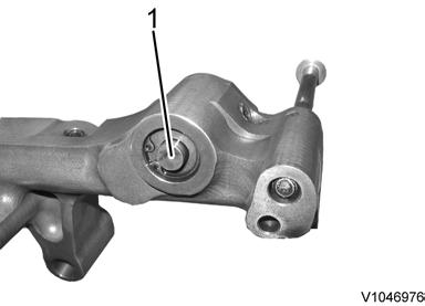
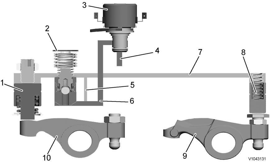
Document Title: Function Group: Information Type: Date: Internal Exhaust Gas Recirculation (IEGR), description 214 Service Information 2014/8/26
Profile: EXC, EC240B FX [GB]
Internal Exhaust Gas Recirculation (IEGR), description
A system for IEGR (Internal Exhaust Gas Recirculation) is used as part of V-ACT (Volvo Advanced Combustion Technology). On D6E and D7E this takes place by an IEGR-opening piston, controlled by the lubrication oil's system pressure, acting on the exhaust rocker arm which enables a second opening of the exhaust valves. When activated, the secondary piston will give a limited valve opening of the exhaust valves during the induction phase, which leads exhausts back into the cylinder.
Included components IEGR-unit
The hydraulic mechanism is housed in two interconnected IEGR-units, located on the rocker arm holders. Lubrication oil is routed from the cylinder head via the solenoid valve to the high-pressure channel in the IEGR-unit through a channel in one of the rocker arm holders.

Solenoid valve
The solenoid valve is located in the cylinder head on the flywheel side and is activated by the EECU via the control system EMS 2. When IEGR is not activated, the solenoid valve is closed and no oil flow is allowed into the IEGR-unit. At activation of IEGR, the solenoid valve opens the channel from the engine's lubrication system to the IEGR-unit.
Control valve
The control valve is located in the IEGR-unit between the high-pressure circuit and low-pressure circuit. When the lowpressure circuit is supplied from the lubrication oil system, the control valve is lifted and closes the high-pressure circuit. The ball in the control valve enables filling of the high-pressure circuit when IEGR is activated. The lubrication oil is drained through the control valve.
Main piston
The main piston is acted on by the adjusting screw on the inlet valve's rocker arm, and affects the oil pressure in the IEGRunit's high-pressure channel. At the end of the IEGR-phase, a pressure of 100 bar is generated in the high-pressure circuit.
Servo piston
The servo piston is activated by the hydraulic pressure from the main piston via a channel in the IEGR-unit when the IEGRfunction is active/on (solenoid valve in open position). Then the servo piston opens the exhaust valves via the rocker arm an extra time during the induction stroke.

Suggest:
If the above button click is invalid.
Please download this document first, and then click the above link to download the complete manual.
Thank you so much for reading
Function
IEGR is activated by the system being supplied with full lubrication oil system pressure via the solenoid valve. The solenoid valve is activated by the E-ECU.
The control valve closes the high-pressure circuit and the ball inside the valve enables filling of the system. With the same movement as the inlet valve's rocker arm opens the valve, the main piston is forced upward. The pressure in the IEGR-unit's high-pressure channel (up to 100 bar) overcomes the spring force in the servo piston. the servo piston forces down the rocker arm, which results in the exhaust valve being open for a short time at the end of the induction stroke. Exhausts from the exhaust manifold are sucked into the cylinder by vacuum from the other cylinders.
The breather hole between the low-pressure channel and the high-pressure channel in the IEGR-unit enables longer exhaust recirculation at high engine speed.
Solenoid valve
2–5 Bar lubrication oil pressure
Breather hole
Oil channel, low-pressure