
Document Title: Function Group: Information Type: Date:
Engine, description (EC240) 210 Service Information 2014/9/10
Profile:
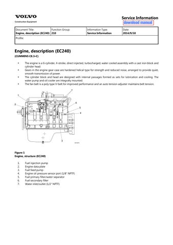
Engine, description (EC240)
(CUMMINS C8.3–C)
The engine is a 6-cylinder, 4-stroke, direct injected, turbocharged, water cooled assembly with a cast iron block and cylinder head.
Gears in the engine gear case are hardened helical type for strength and reduced noise, arranged to provide quiet, smooth transmission of power.
The cylinder block and head are designed with internal passages formed as sets for lubrication and cooling. The water pump and oil cooler are integrally mounted.
The fan belt is a poly type V-belt for improved performance and an auto tension adjuster maintains belt tension.
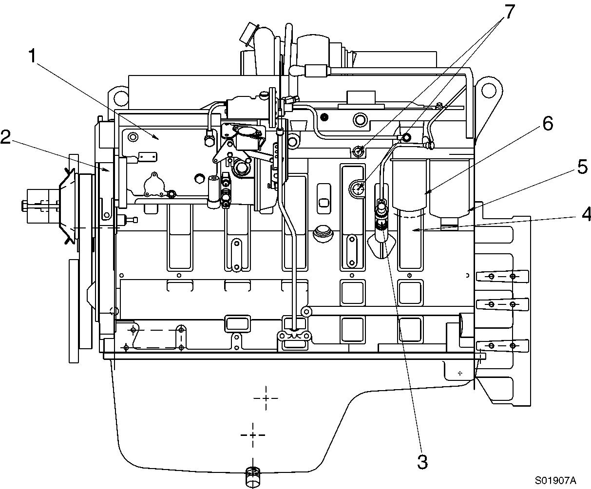
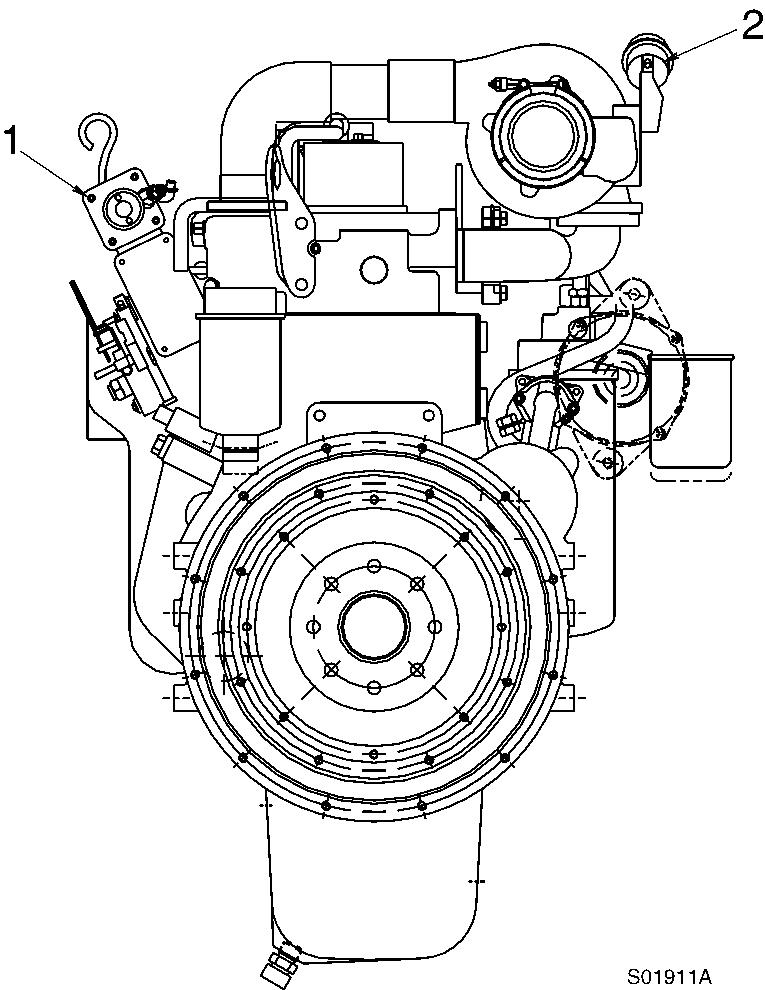
Fuel injection pump
Engine data plate
Fuel feed pump
Engine oil pressure sensor port (1/8″ NPTF)
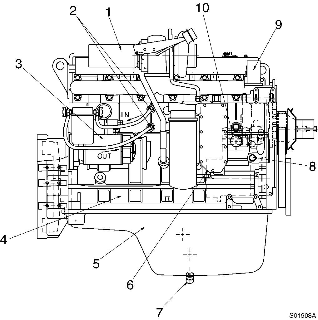
Fuel primary filter/water separator
Fuel secondary filter
Water inlet/outlet (1/2″ NPTF)
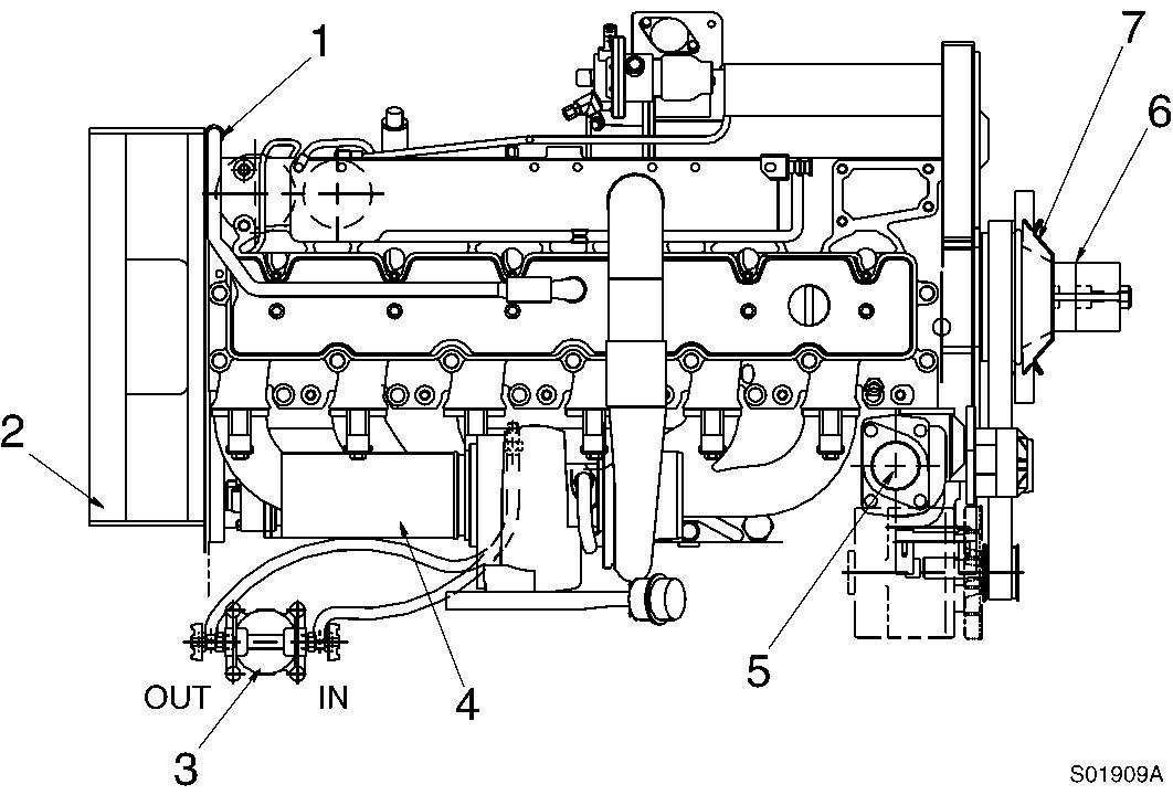
Breather hose
Flywheel housing
Water filter
Exhaust gas pipe
Thermostat
Fan spacer
Fan drive pulley
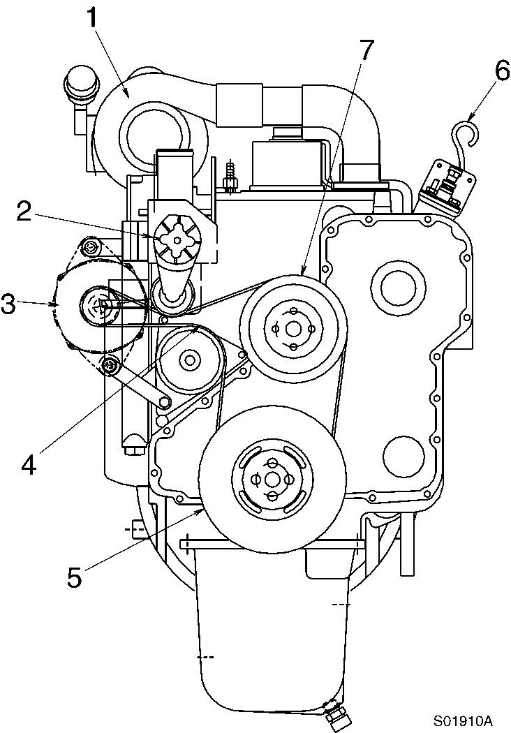
Turbocharger
Automatic belt tensioner
Alternator
Fan belt
Vibration damper
Dipstick gauge
Fan drive pulley
Exhaust gas discharge port
Water filter connecting port (1/2″ NPTF)
Starter
Engine block Oil pan
Engine oil cooler
Engine oil drain valve (M18 × 1.5P)
Temperature switch (for auto warm - up)
Water outlet
Water inlet
Engine characteristic curve
Engine characteristics
Specification
Rated output
Max. torque (Net)
Min. fuel consumption
Rated fuel consumption
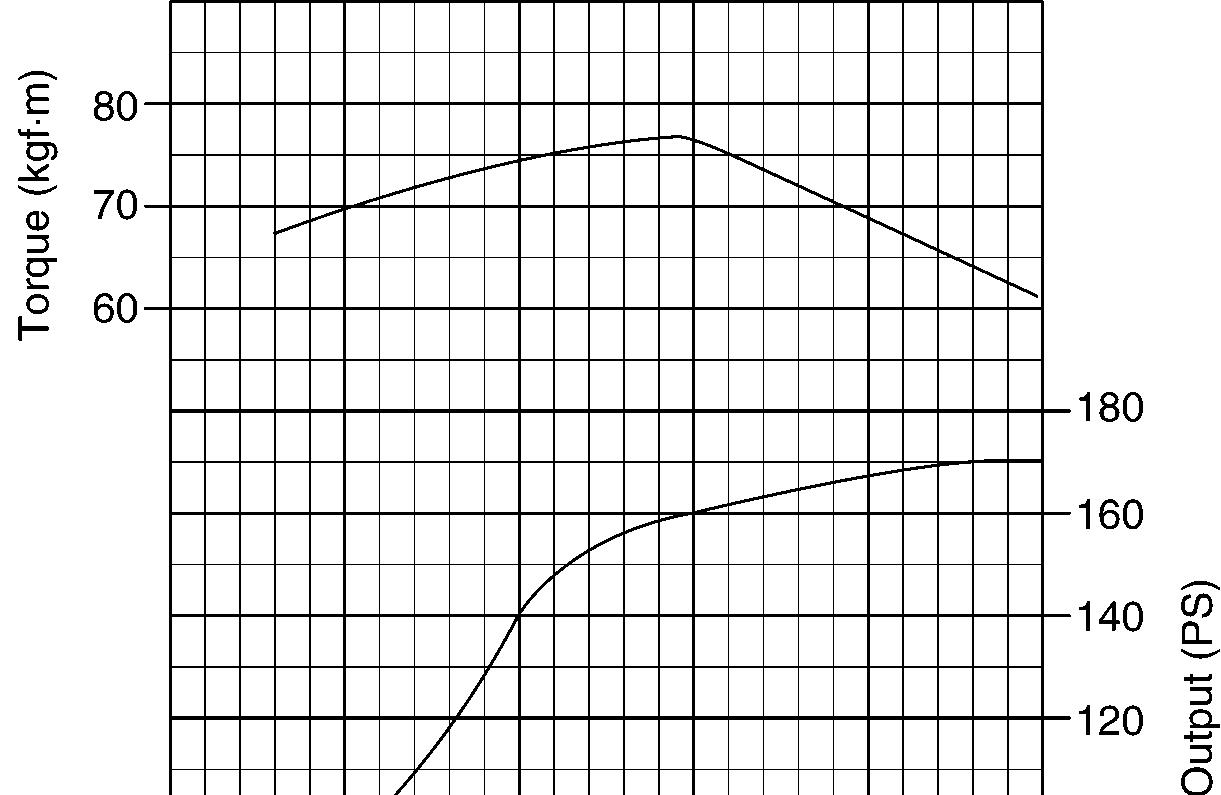
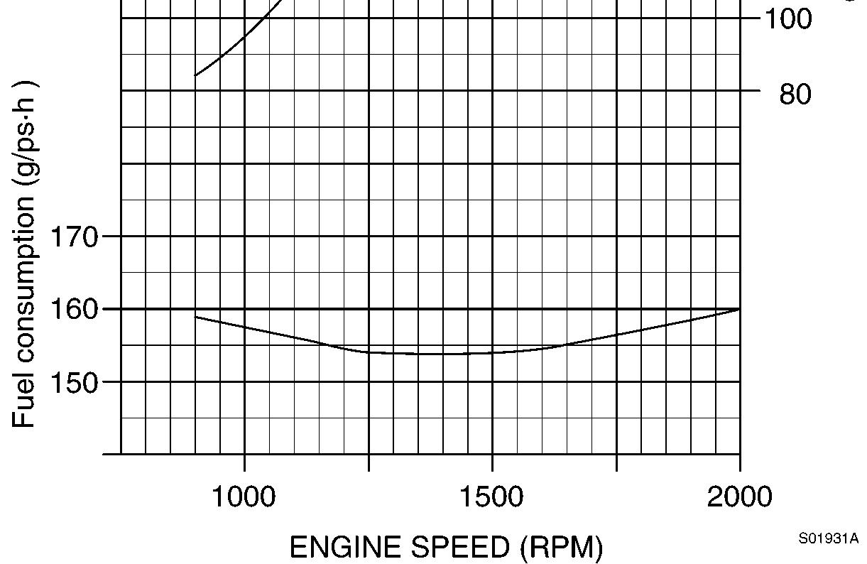
Engine, characteristic curve (EC240)
NOTE!
170 ps / 2000 rpm
76.5 kgf·m / 1500 rpm (552 lbf·ft / 1500 rpm)
154 g / ps·h
160 g / ps·h
For detailed information on the engine, consult the separate engine service manual.
Document Title: Function Group: Information Type: Date: Engine, specifications 210 Service Information 2014/9/10
Profile:
Engine, specifications
Specifications
Item
Make – Cummins diesel
Model
Type
Rated output
/ rpm
B 5.9–C C 8.3–C
4–stroke, 6–cylinder, water cooling, upright series, direct injection, diesel engine, turbo-charged, aftercooled 4–stroke, 6–cylinder, water cooling, upright series, direct injection, diesel engine, turbo-charged
/ 1900
/ 2000
/ 1500 (722 /1500) Number of cylinder Bore×Stroke
6 – 102 × 120 6 – 114 × 135
Compression ratio
Turbocharger
Document Title: Function Group: Information Type: Date:
Valve clearance adjustment 214 Service Information 2014/9/10
Profile:
Valve clearance adjustment
Cummins B5.9–C (EC210 series)
Valves must be correctly adjusted for the engine to operate efficiently. Valve adjustment must be performed using the specified values.
Adjust the valves at each 1000 hours or 1 year maintenance interval.
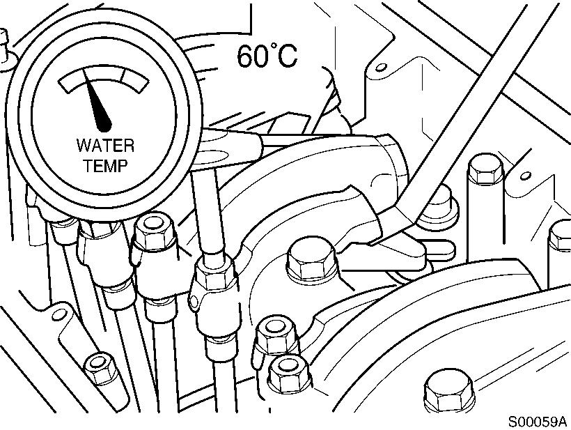
All the valve adjustments must be made when the engine is cold and stabilized coolant temperature is 60°C or below.
Turn the valve adjustment screws in until touching the push rod sockets, and then loosen them one full turn. Use 1/2″ drive, Part No. 3377371 Engine Barring Tool.
Valve clearance adjustment condition
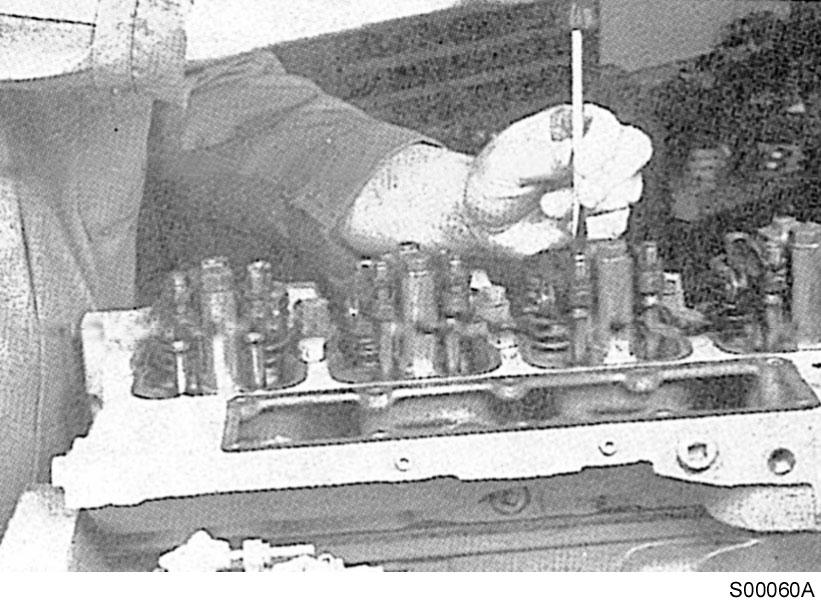
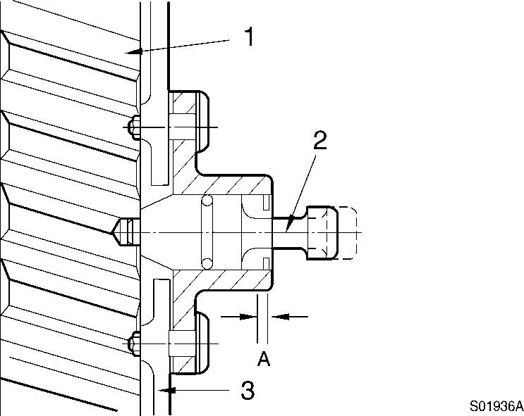
Locate top dead center for cylinder No.1 by rotating the crankshaft slowly while pressing on the engine timing pin. When the pin engages the hole in the camshaft gear, cylinder No.1 is at top dead center on the compression stroke.
3
Rotation, camshaft gear
Camshaft gear
Timing pin
Gear housing A. Compression stroke

CAUTION
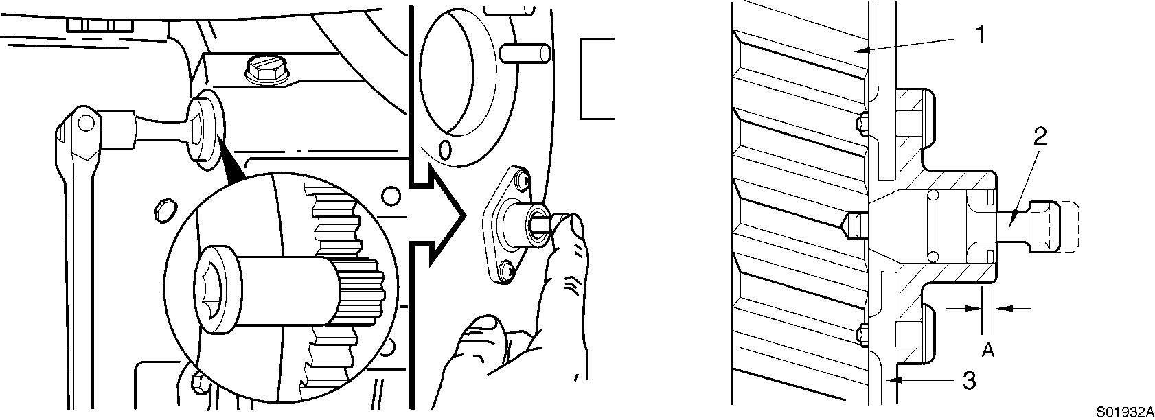
Disengage the timing pin. Engine components may be damaged if the engine is rotated with the timing pin engaged.
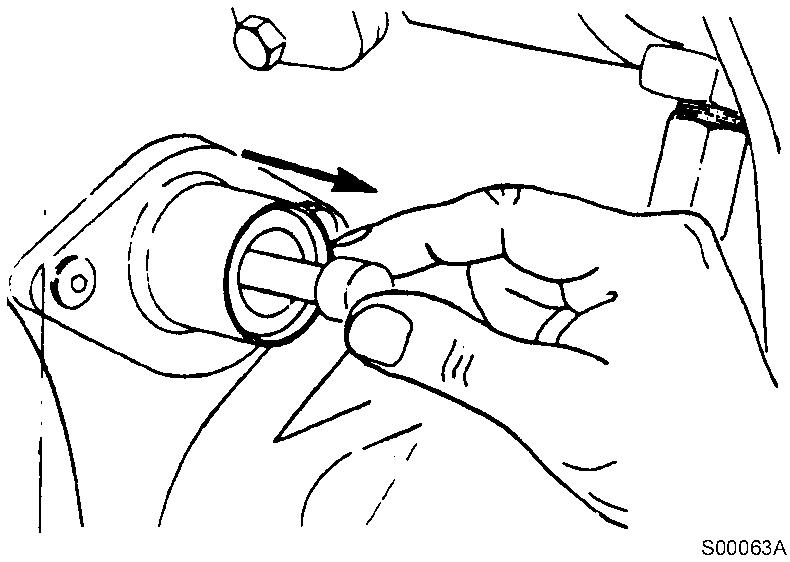
Figure 4
Removal, timing pin
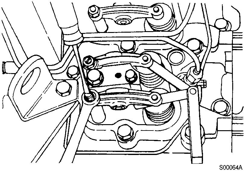
Figure 5
Adjustment, clearance between the valve stem and rocker lever
Tools : 14 mm spanner, “-” screwdriver, feeler gauge.
The clearance is correct when slight resistance is felt as the feeler gauge is moved between the valve stem and rocker lever. At that point, tighten the lock nut. (Tightening torque : 24 N·m)
Adjust the valves indicated (∗) in the table below.
After tightening the lock nut, check the valve clearance again. If the clearance is not correct, readjust.
Valves to be adjusted ( )

Figure 6
Valves to be adjusted
CAUTION
Be sure the timing pin is disengaged.
NOTE!
Mark the crankpulley and cover.
NOTE!
Rotate the crankshaft 360°.
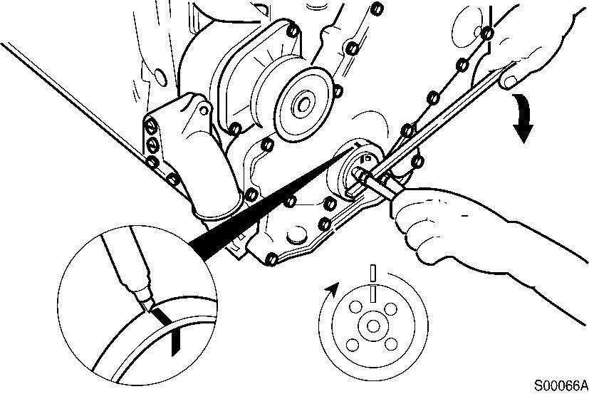
Figure 7
Marking, crankpulley
Adjust the valves indicated (∗) in the table below.
After tightening the lock nut, check the valve clearance again. If the clearance is not correct, readjust.
Valves to be adjusted ( )
Cylinder 1 2 3 4 5 6
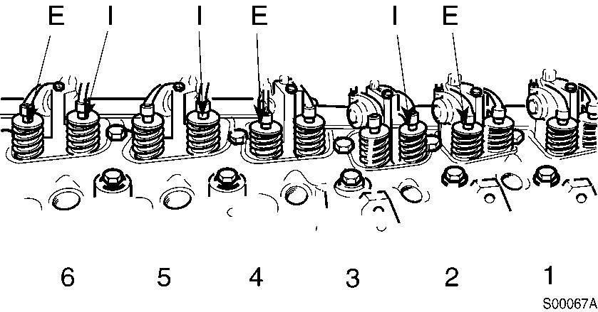
Figure 8
Valves to be adjusted
Assemble the gaskets, valve covers, o-rings and special screws.
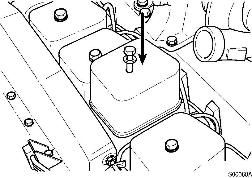
Figure 9
Assembly, valve covers
Tools : 16 mm spanner
Tightening torque : 24 N·m (18 lbf·ft)
NOTE!
Check valve covers and o-rings. If damaged, replace with a new one.
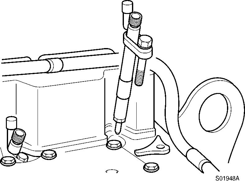
Injection nozzles installation
Assemble a sealing washer on each injection nozzle. Use only one sealing washer.
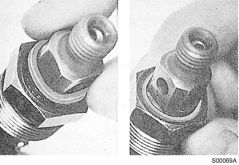
Figure 10
Assembly, injection nozzles
Apply anti–seize compound to the threads of the injector hold–down nut and between the top of the nut and injector body.
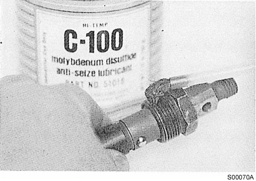
Figure 11
Apply, anti-seize compound
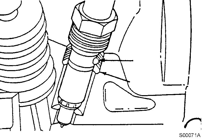
Figure 12
Installation, injection nozzle
Tools : 16 mm spanner, 24 mm Deep socket
Tightening torque : 60 N·m (44 lbf·ft)
NOTE!
Install the injection nozzle. The protrusion on the injector body fits into a notch in the cylinder head to position the injector. Tighten the injection nozzle nuts.
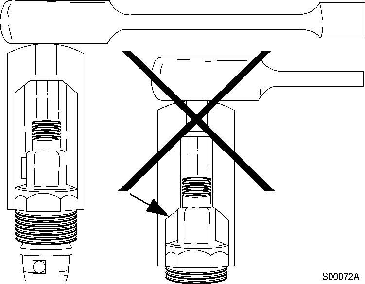
13
Tightening, injection nozzle
NOTE!
Some sockets can damage the sealing surface of the fuel drain outlet.
Cummins C8.3–C (EC240 series)
Valve clearance adjustment
Valves must be correctly adjusted for the engine to operate efficiently. Valve adjustment must be performed using the specified values.
Adjust the valves at each 1000 hours or 1 year maintenance interval.
All the valve adjustments must be made when the engine is cold, and stabilized coolant temperature is 60°C or below.
14
Adjustment condition
Valve clearance
Inlet valve
Exhaust valve
Remove the air inlet hose.
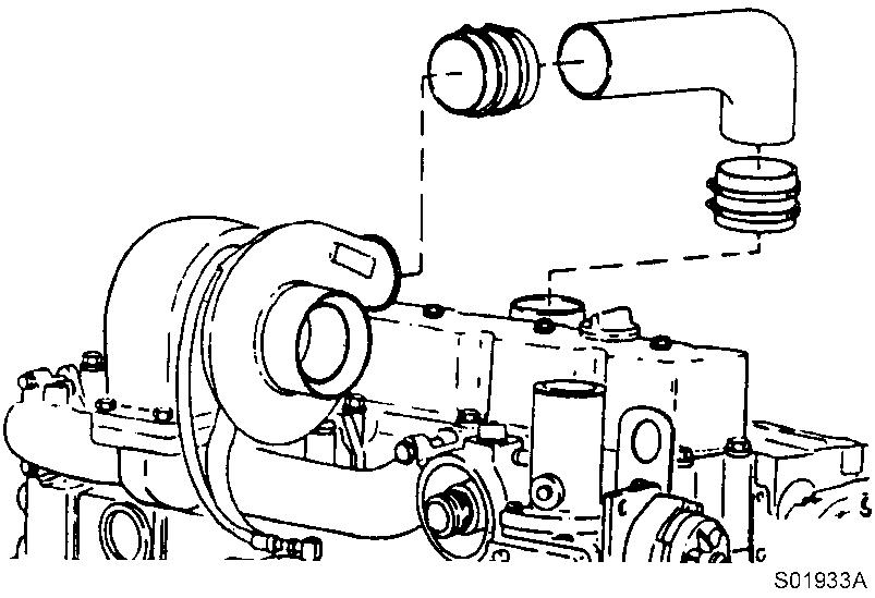
Figure 15
Removal, inlet hose
mm
mm
in
in
Remove the wastegate sensing line, support clamps and crankcase vent tube.
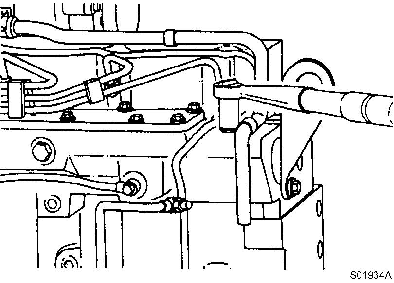
Figure 16
Removal. crankcase vent tube
Tools : 13, 18 mm Socket
Remove the valve cover.
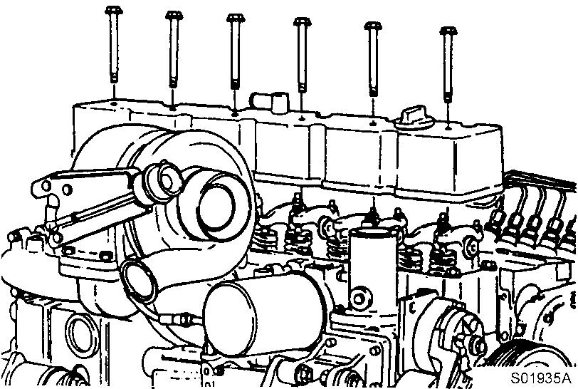
Figure 17
Removal, valve cover
Tools : 15 mm Wrench
Locate top dead center for cylinder No.1 by rotating the crankshaft slowly while pressing on the engine timing pin.
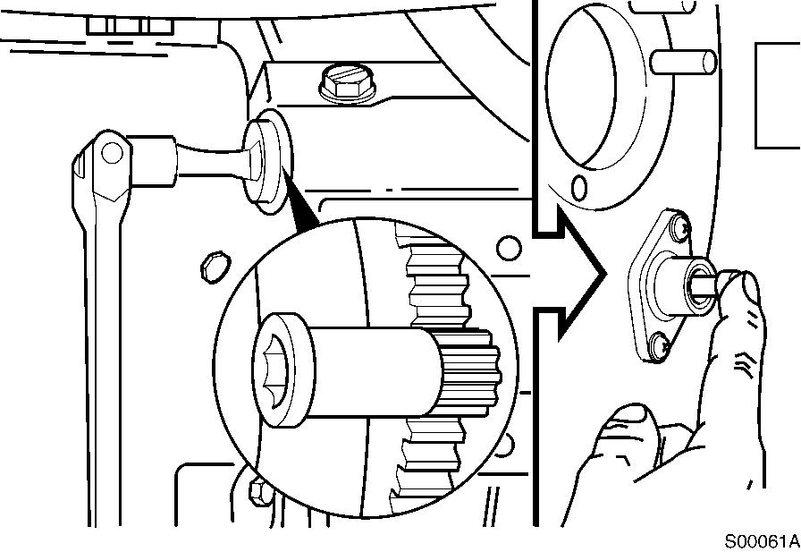
Figure 18
Rotation, camshaft gear
Tools : 1/2″ driver, Part No. 3377371 Engine Barring tool.
When the pin engages the hole in the camshaft gear, cylinder No. 1 is at top dead center on the compression stroke.
A. Compression stroke
CAUTION
Disengage the timing pin. Engine components may be damaged if the engine is rotated with the timing pin engaged.
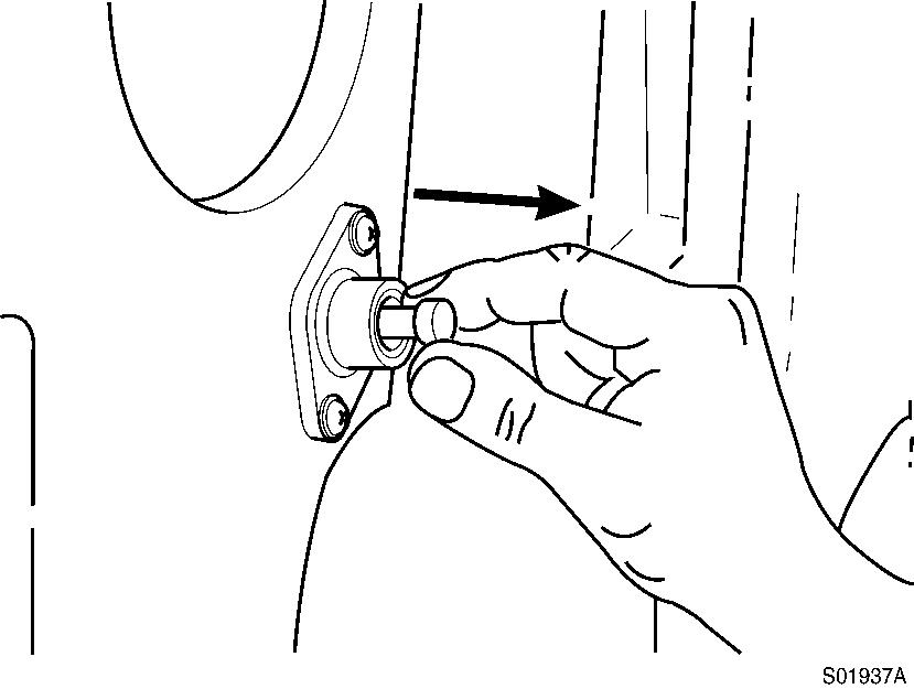
Figure 20
Removal, timing pin
CAUTION
To prevent damage of push rod, make sure the adjusting screw ball is positioned in the socket of the push rod when tightening.
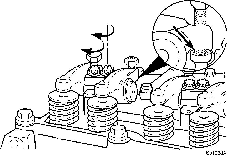
Figure 21
Position, adjusting screw ball
The clearance is correct when slight resistance is felt as the feeler gauge is moved between the valve stem and rocker lever.
At that point, tighten the lock nut.
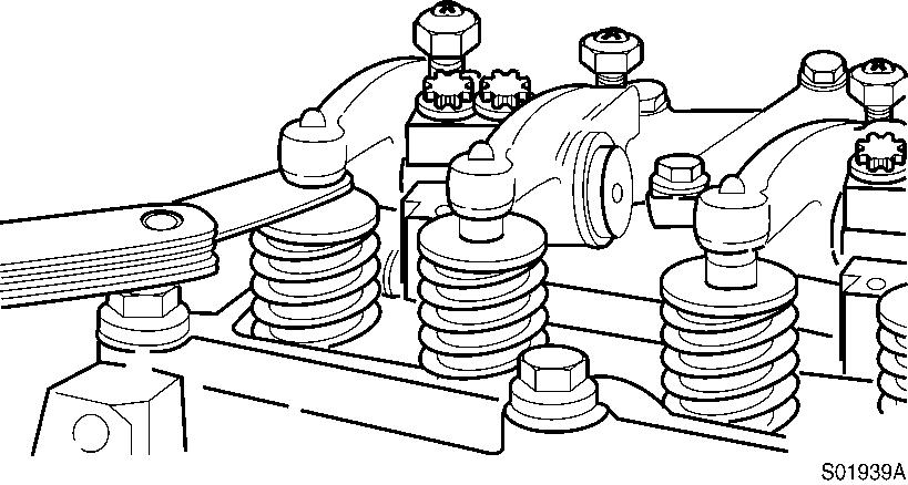
Figure 22
Checking, clearance
Tools : Spanner 14mm, “-” Driver, feeler gauge.
Adjust the valves indicated (∗) in the table below.
After tightening the lock nut, check the valve clearance again.
If the clearance is not correct, readjust.
Valves to be adjusted ( ) Cylinder 1 2 3 4 5 6
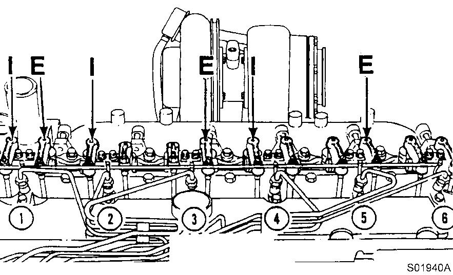
23
Valves to be adjusted
CAUTION
Be sure the timing pin is disengaged.
Mark the crankpulley and cover. Rotate the crankshaft 360°.
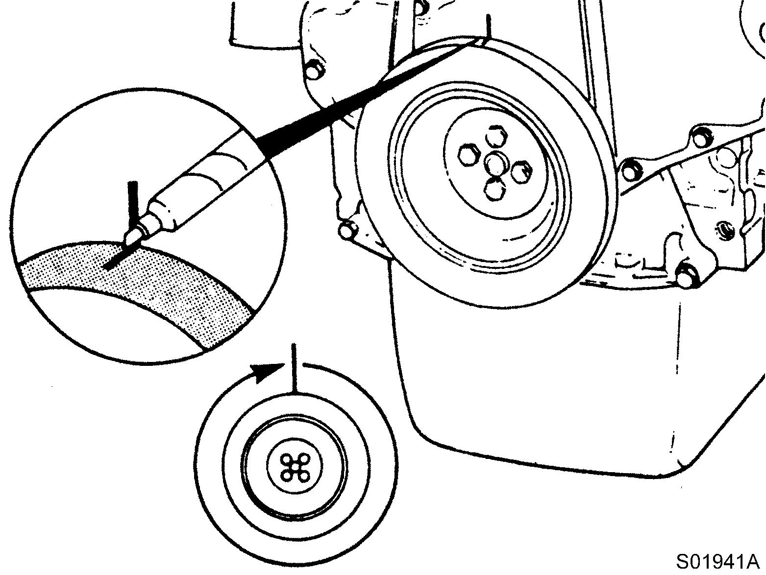
24
Marking, crankpulley
Adjust the valves indicated (∗) in the table below.
After tightening the lock nut, check the valve clearance again. If the clearance is not correct, readjust.
Valves to be adjusted ( ) Cylinder 1 2 3 4 5 6
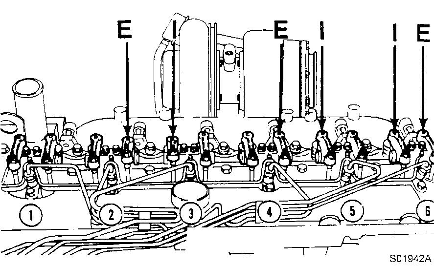
Figure 25
Valves to be adjusted
Valve cover–installation
Install the rubber seal into the groove in the valve cover. Start the installation at the overlap area shown in the illustration.
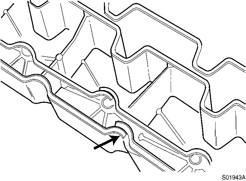
Figure 26
Assembly, rubber seal
Do not stretch the rubber seal. If the seal has more overlap than shown in this illustration, trim the excess to provide the proper overlap. Install new o-rings on the valve cover screws.
27
Assembly, o-ring
NOTE!
Engines equipped with wastegate turbochargers must have a studded screw installed in the third hole from the front. This is for the wastegate actuator hose clamp.
Install the valve cover screws and tighten in the sequence shown.
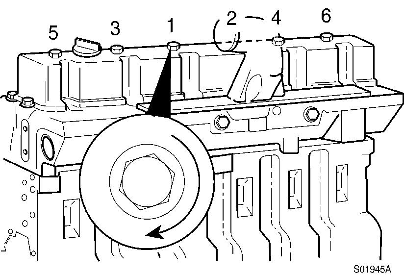
Figure 28
Screw tightening sequence
Tools : 15 mm spanner
Tightening torque : 24 N·m (18 lbf·ft)
Crankcase breather tube–installation
Install the breather tube and hose clamps. Tighten the screws for the breather tube support brackets.
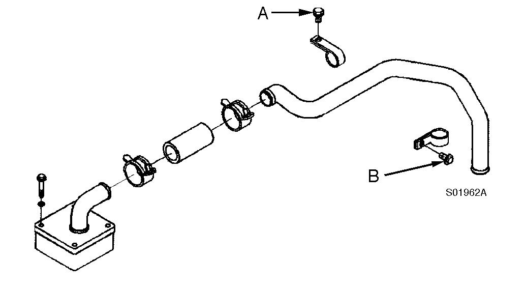
Figure 29
Assembly, breather tube
Tightening torque : A = 24 N·m (18 lbf·ft), B = 43 N·m (32 lbf·ft)
Tools : 13, 18 mm spanner
Injection nozzles–installation
Lubricate the sealing lips of the sleeve with anti-seize compound. Assemble the injection nozzle, the sealing sleeve, a new copper washer and the hold-down clamp.
Use only one washer.
A light coat of clean 15W–40 engine oil between the washer and the injection nozzle will aid in holding the washer in place during installation.
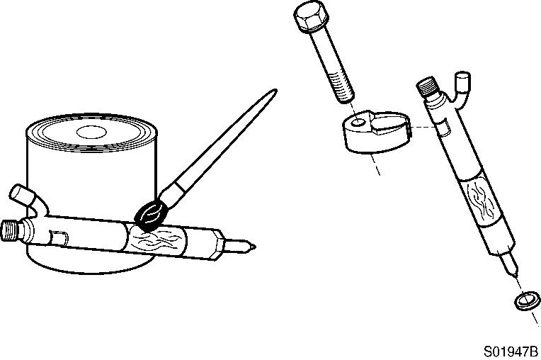
Apply, anti-seize compound
Install the hold-down injection nozzle assembly into the injection nozzle bore. The injector leak–off connection must be toward the valve cover.
31
Assembly, injection nozzle
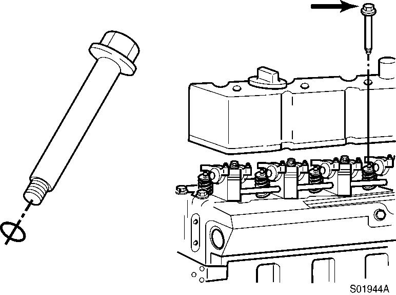
Install the hold-down screw.
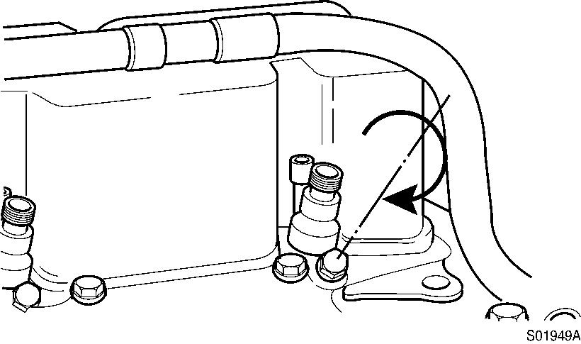
Figure 32
Screw in, hold-down screw
Tightening torque : 24 N·m (18 lbf·ft)
Tools : 13 mm spanner

Thank you so much for reading Download
If the above button click is invalid. Please download this document first, and then click the above link to download the complete manual.
Document Title: Function Group: Information Type: Date:
Engine mounting 218 Service Information 2014/9/10
Profile:
Engine mounting
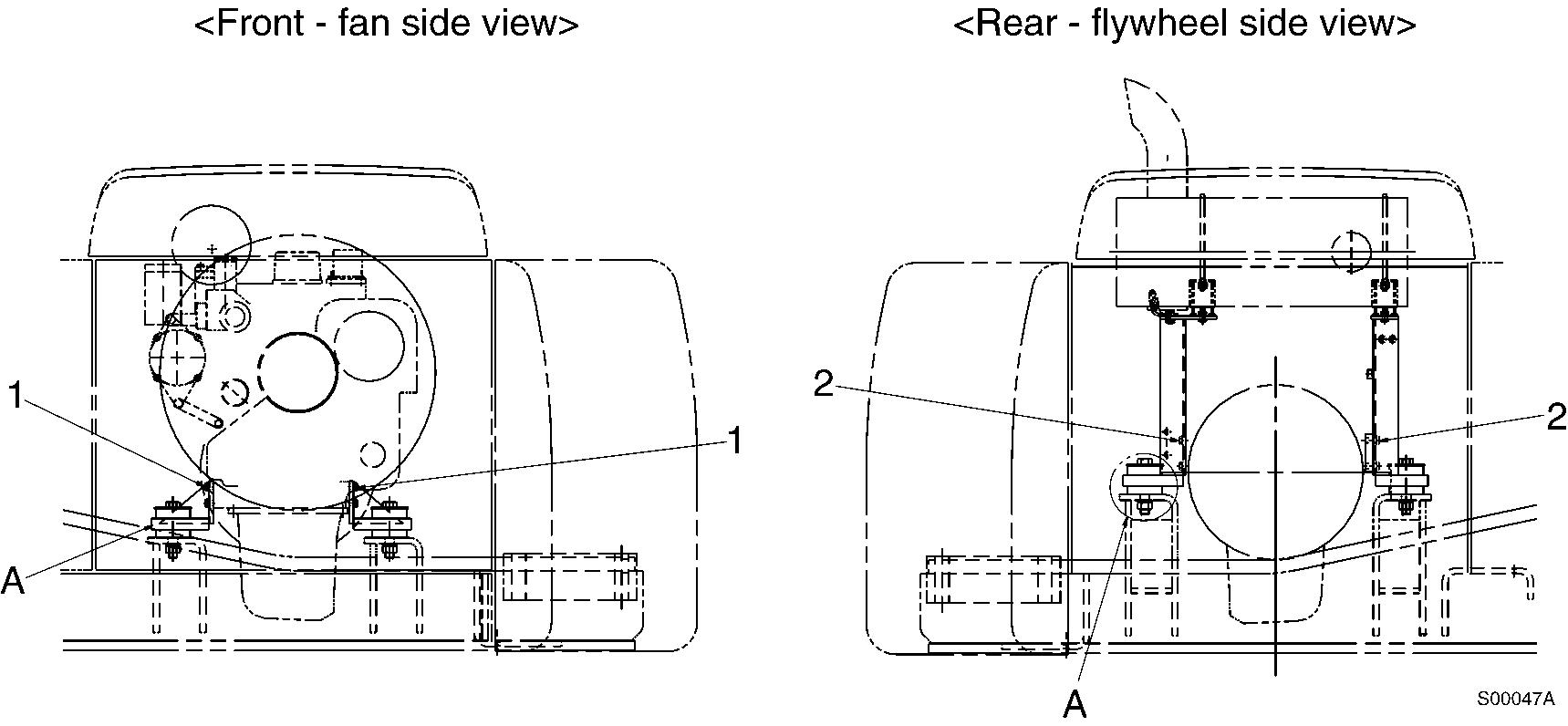
1
Engine mounting, side view
Tightening torque, unit : kgf·m (lbf·ft)
No. Mounting position
M12 x 1.75 x 35L M12 x 1.75 x 30 1 Engine mounting bracket (front) 11 ~ 12 (79 ~ 87) M12 x 1.75 x 35L
Engine mounting bracket (rear) 7.2 ~ 8.4 (52 ~ 61) M22 x 2.5 x 130L 3 Engine mounting cushion 63 ~ 76 (455 ~ 549)
NOTE!
Check the color markings for cushion installation.
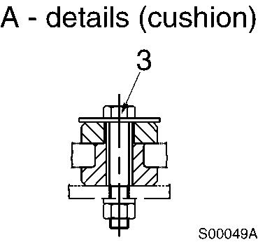
Front (fan side)–Yellow and white Rear (flywheel side)–Blue and white
x 1.75 x 50L