
Document Title: Function Group: Information Type: Date: Engine, description 200 Service Information 2014/9/24
Profile:
EXC, ECR305C L [GB]
Engine, description
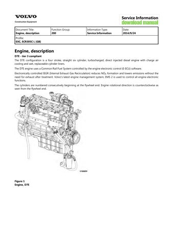
D7E - tier 3 compliant
The D7E configuration is a four stroke, straight six cylinder, turbocharged, direct injected diesel engine with charge air cooling and wet, replaceable cylinder liners.
The D7E engine uses a Common Rail Fuel System controlled by the engine electronic control (E-ECU) software.
Electronically controlled IEGR (Internal Exhaust Gas Recirculation) reduces NO formation and lowers emissions without the need for exhaust after treatment. Volvo's latest engine management system, EMS 2 is used to control all engine electronic functions.
The cylinders are numbered consecutively beginning at the flywheel end. Engine rotational direction is counterclockwise as seen from the flywheel end.
Document Title: Function Group: Information Type: Date: Engine, identification 200 Service Information 2014/9/24
Profile:
EXC, ECR305C L [GB]
Engine, identification
Identification plate
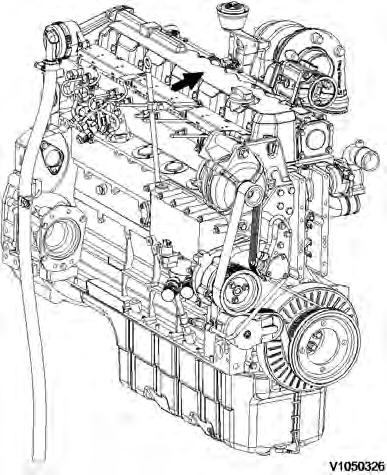
The engine model, serial number and performance data are stamped on an identification plate which is attached on the cylinder head cover. The engine model designation and serial number must be indicated when ordering spare parts.
Document Title: Function Group: Information Type: Date:
Engine, tightening torques 200
Profile:
EXC, ECR305C L [GB]
Engine, tightening torques
NOTICE
Service Information 2014/9/24
Regarding bolted joints which are not listed here, see “Volvo standard tightening torques”
Engine, tightening torque
Rocker arm bracket on cylinder head
Cylinder head cover (M6) on cylinder head
Exhaust return module on cylinder head
Lock nut, valve adjusting screw
Locking screw on cylinder head
Solenoid valve on cylinder head
Front cover on crankcase
Drain plug on oil pan, M18
Crankcase ventilation on cylinder head
Return line to return stop valve
Return stop valve to crankcase
30 Nm (22.2 lbf ft)
13 Nm (9.6 lbf ft)
Step 1: 10 Nm (7.4 lbf ft)
Step 2: 30 Nm (22.2 lbf ft)
20 ±2 Nm (14.8 ±1.5 lbf ft)
34 Nm (25.2 lbf ft)
24 Nm (17.8 lbf ft)
Step 1: 3 Nm (2.2 lbf ft)
Step 2: 21 Nm (15.5 lbf ft)
55 Nm (40.7 lbf ft)
21 Nm (15.5 lbf ft)
30 Nm (22.2 lbf ft)
Nm (59.2 lbf ft)
Impulse transmitter (crankshaft) on holder on front cover 9 Nm (6.7 lbf ft)
Impulse transmitter (camshaft) on gearcase 9 Nm (6.7 lbf ft)
Turbocharger on exhaust manifold
42 Nm (31.1 lbf ft)
Clamping shoe injector on cylinder head 16 Nm (11.8 lbf ft)
Injection lines on rail and injector, high pressure line on high-pressure pump 25 Nm (18.5 lbf
Fuel supply pump on holder
Holder fuel supply pump on holder
V-belt pulley on fuel supply pump
High pressure pump on crankcase, M10
Fuel control valve
Fuel pipe on high pressure pump
Fuel pipe on control block
Rail on cylinder head
Pressure relief valve on rail
Rail pressure sensor on rail
Pipe clips, fuel line fastening
Fuel line on control block, fuel filter console and rail
Fuel pipe (return) on control block
Fuel pipe (return) on cylinder head
Fuel line on fuel filter8
Fuel filter console/radiator tank on crankcase
(20.0 lbf ft)
Step 1: 10 Nm (7.4 lbf ft)
Step 2: 50 Nm (37.0 lbf ft)
Nm (21.5 lbf ft)
Nm (28.9 lbf ft)
Nm (22.2 lbf ft)
Nm (74.0 lbf ft)
Nm (51.8 lbf ft)
Nm (22.2 lbf ft)
Nm (36.3 lbf ft)
Nm (21.5 lbf ft)
Nm (28.9 lbf ft)
Nm (22.2 lbf ft)
Cover plate on cylinder cover, M6
Document Title: Function Group:
EXC, ECR305C L [GB]
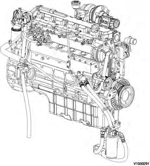
Component locations
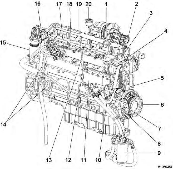
Component position, engine D7E. The following figures show the position of a number of components on engine D7E. Figure 1
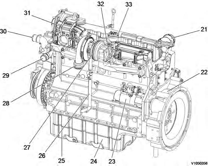
2 Component locations, flywheel side
21 Crankcase bleeding valve
22 Flywheel housing
Air outlet (to charge air cooler)
Coolant inlet 23 Starter motor
Coolant outlet 24 Oil pan
25 Drain plug
26 Oil return line from turbocharger
Air inlet (from charge air cooler)
Exhaust manifold
Cylinder rocker arm cover 27 Turbocharger
Document Title: Function Group: Information Type: Date:
Engine characteristic curve 210 Service Information 2014/9/24
Profile:
EXC, ECR305C L [GB]
Engine characteristic curve
1
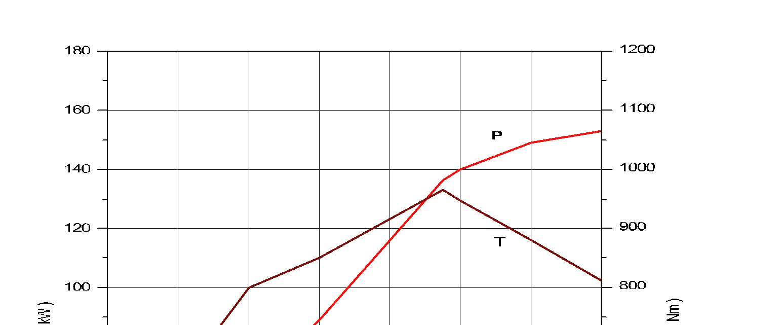
Engine, characteristic curve
P Output power
rpm Engine speed
T Torque
be Fuel consumption
Document Title: Function Group: Information Type: Date: Basic check, Engine 210 Service Information 2014/9/24
Profile:
EXC, ECR305C L [GB]
Basic check, Engine
NOTE!
Certain tests and checks are performed with unlocked safety locking lever. Make sure that the machine cannot operate unexpectedly when the control lockout lever is unlocked.
Purpose of the basic check
The purpose of the basic check is to provide fast and accurate information about the general condition of the engine.
The basic check should be performed and evaluated according to instructions in the PC-tool VCADS Pro.
Tests included in the basic check
The basic check which is divided into the following tests should be performed after reading out error codes and checking parameters
Tests:
1. 2. 3. Cylinder compression, test
The purpose of the test is to show if any cylinder has a deviating compression pressure. The test replaces the old pressure check method but does not give any absolute values.
Feed pressure, test
The purpose of the test is to check that the feed pressure is as per specification.
Sensor, test
The purpose of the test is to check the function of all sensors.
Document Title: Function Group: Information Type: Date:
Troubleshooting 210 Service Information 2014/9/24
Profile:
EXC, ECR305C L [GB]
Troubleshooting
General about troubleshooting
When a malfunction is suspected or has been confirmed, it is important to identify the cause as soon as possible. The starting point for all troubleshooting is that there is some type of trouble symptom or malfunction. Malfunctions can be indicated by:
generation of error codes detection of a malfunction symptom.
Troubleshooting work
The first step in troubleshooting is to gather information from the operator concerning the malfunction symptoms, see Electrical and information system, Collection of basic data. Then, attempt to pin-point the cause by checking in a certain order, for more information, see Electrical and information system, troubleshooting strategy. The different checking steps are:
Check error codes
Check parameters
Perform basic check
Troubleshooting information
The following is included in Electrical and information system and is used when troubleshooting:
Troubleshooting strategy
Describes troubleshooting work, step by step.
Troubleshooting, assistive devices
Brief summary of the assistive devices that are available for troubleshooting.
Functional checks and tests, VCADS Pro
Brief description of VCADS Pro. For a detailed description, see VCADS Pro User’s Manual.
Error code information
Contains information regarding error code design, lists of all error codes and error code information about each error code.
Components, troubleshooting and specifications
Contains methods and measuring values for troubleshooting of components. Also includes wiring diagrams and certain specifications.
Parameters
Incorrectly set parameters may cause malfunction symptoms. The parameter list includes all limit and command values for parameters.
Control units, functional description
Describes the functions of the control units, inputs and outputs as well as communication between the various control units.
Control units, active and passive measuring
Contains measuring values for active and passive measuring of the ECUs.
Software functions
Describes the pre-requisite conditions for the control and monitoring functions that are performed by the software in the ECUs.
Document Title: Function Group: Information Type: Date: Camshaft and flywheel signals, checking with VCADS Pro and oscilloscope 210 Service Information 2014/9/24
Profile: EXC, ECR305C L [GB]
Camshaft and flywheel signals, checking with VCADS Pro and oscilloscope
Op nbr 210-090
9990014 Break out harness
9990062 Cable
9998699 Adapter
88890040 Oscilloscope VCADS Pro VCADS Pro Service Tool
1. Connect 88890040 Oscilloscope to the VCADS Pro computer and perform 28420-3, Flywheel and camshaft signals, test.
NOTE!
Instructions for how to connect the equipment are described in the VCADS Pro operation.
NOTE!
To be able to start the oscilloscope operation when USB-interface is default in VCADS Pro, then 88890180 Interface must be connected to the computer. However, in this case the interface does not have to be connected to the machine.
For computers with only one USB-port, the interface configuration must be changed to 9998555. However, in this cases the interface does not have to be connected to the machine.
Detailed user support is available under the the menu Help in the software.
NOTE!
The function “Save” overwrites the original file. Therefore, choose “Save as...” to save the read-off.
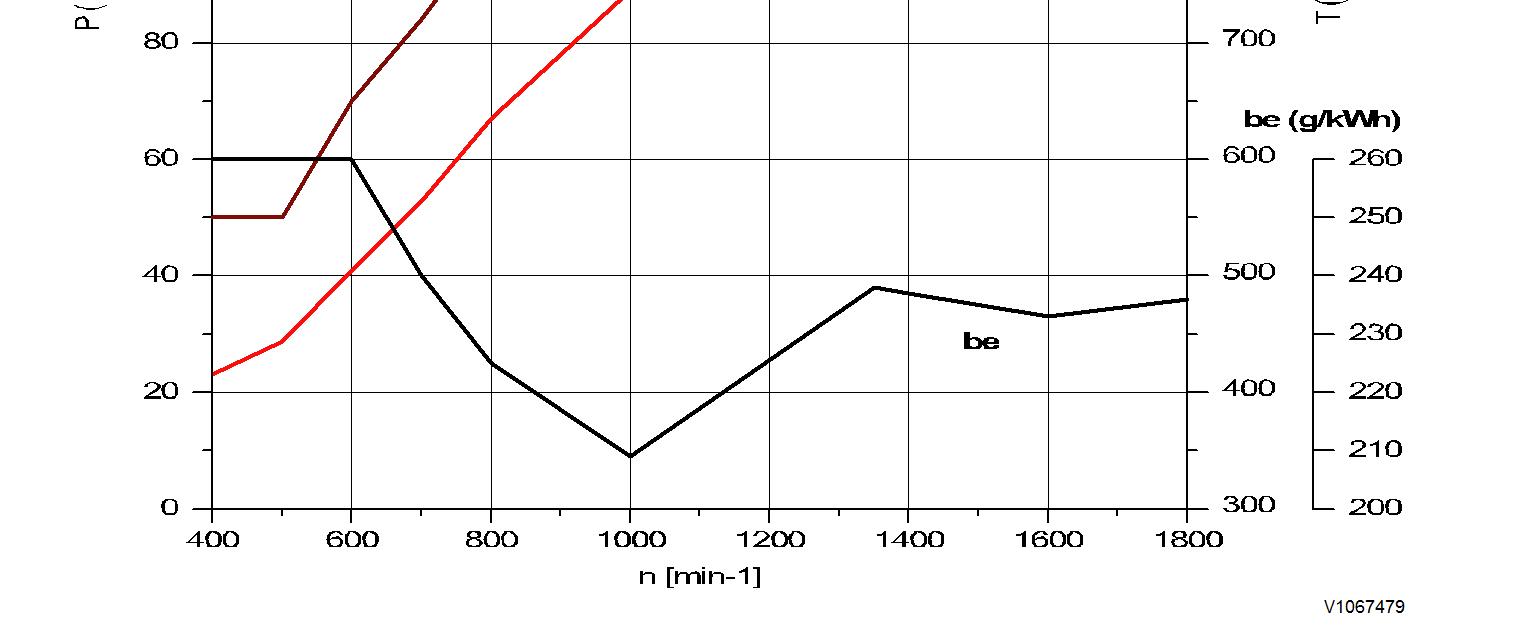
1. Click to start and stop the read-off
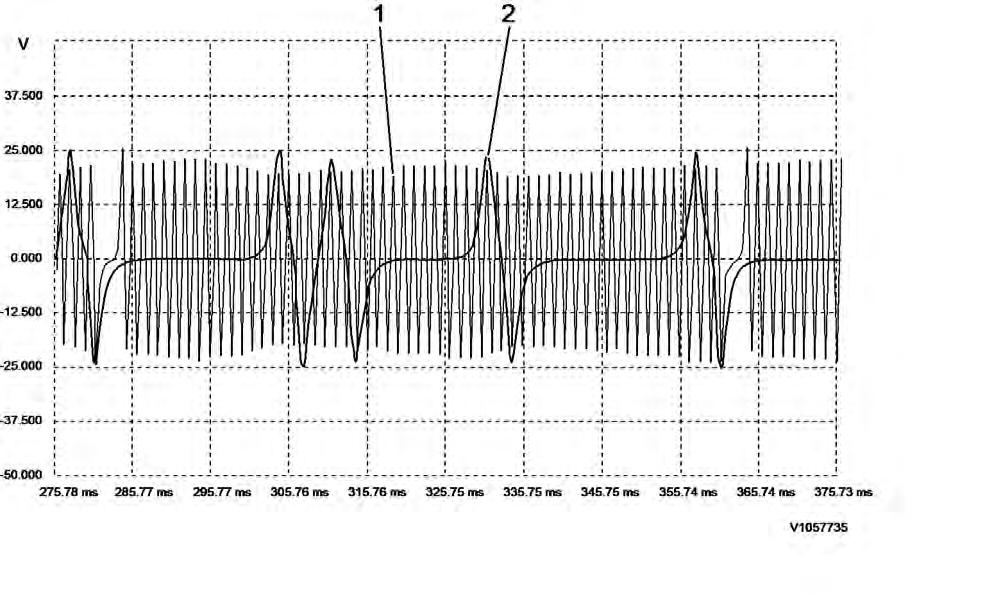
Example of read-off of sensor signals with oscilloscope
1. 2. Signal from flywheel sensor Signal from camshaft sensor
2. Check that the signal from the camshaft sensor's signal coincides with the signal from the flywheel sensor within the marked area in the figure.
If the signal for the camshaft sensor is displaced to the left the camshaft is displaced one gear tooth in the camshaft's rotational direction
If the signal for the camshaft sensor is displaced to the right the camshaft is displaced one gear tooth opposite to the camshaft's rotational direction
For adjusting the camshaft's position, see service manual for respective engine.
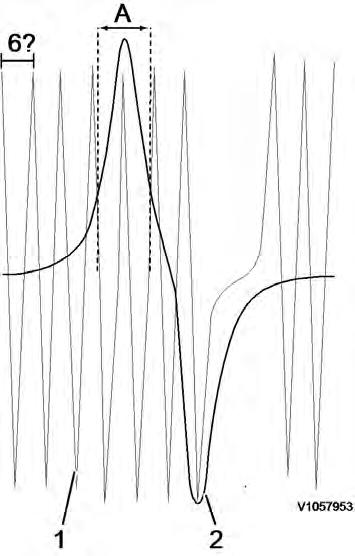
Figure 3
Relationship between camshaft signal and flywheel signal
A. Area where the signal from the camshaft shall coincide with the signal from the flywheel sensor
1. 2. Flywheel sensor Camshaft sensor
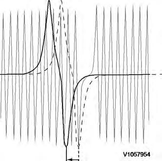
Figure 4
Example of incorrect signal
In this case, the signal for the camshaft sensor is displaced to the left.
3. Check that the curves are not mirror-imaged (see figure). If the curves are mirror-imaged:
Check the connection to the oscilloscope. If the connection to the oscilloscope is correct, check that the connections for the crankshaft sensor are installed correctly. If needed, unplug the connector for the flywheel sensor and change place of the cable connections.

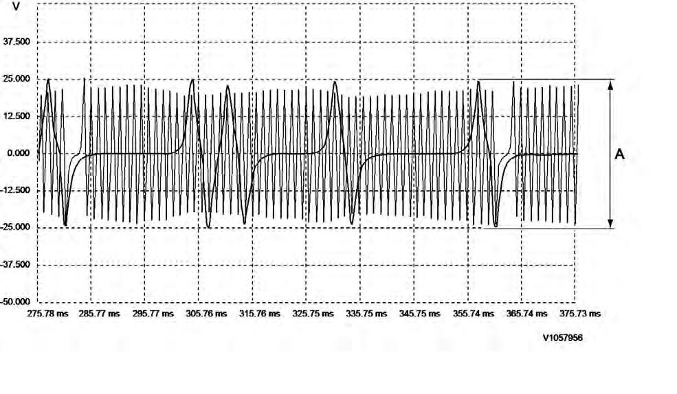
Figure 5
Example of incorrect signal
In this case, the signal for the flywheel sensor is mirror-imaged
4. Check the voltage across the camshaft sensor.
To ensure reliable start and operation of the engine, the voltage across the sensors shall be according to 3021 SE2703, description and measuring
If the signal is too low:
Check that the sensor is correctly installed and adjusted. Remove the sensor and check that it is not damaged. Check the distance between the sensor and the sensor ring gear is according to . Install the sensor 386 Engine rotation speed sensor (camshaft), replacing and check the signal again.
If the sensor is damaged, rotate the crankshaft and check if the camshaft gear has any damage that has caused damage to the sensor.
5. Check the voltage across the flywheel sensor.
To ensure reliable start and operation of the engine, the voltage across the sensors shall be according to
3021 SE2701, description and measuring
If the signal is too low:
Check that the sensor is correctly installed and adjusted. Remove the sensor and check that it is not damaged. Check the distance between the sensor and the sensor ring gear/flywheel is according to . Install the sensor 386 Engine rotation speed sensor, replacing and check the signal again. If the sensor is damaged, rotate the crankshaft and check if the flywheel has any damage that has caused damage to the sensor.

Document Title: Function Group: Information Type: Date:
Cylinder head, description 211 Service Information 2014/9/24
Profile:
EXC, ECR305C L [GB]
Cylinder head, description
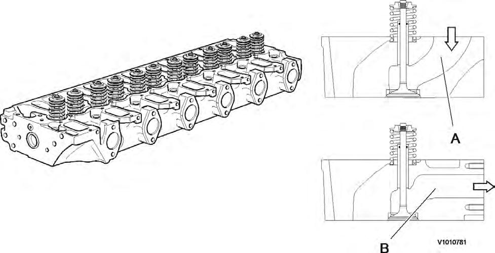
The cylinder head is made of grey cast iron and is common for all cylinders. The induction air enters vertically (A) and the exhausts leave horizontally (B). Inlets and exhaust outlets are located on the same side of the cylinder block. Inlet and exhaust valve size is increased to optimize the gas exchange and combustion process. Valve guides are replaceable. Coolant flow in the cylinder head is modified to accommodate an outlet controlled cooling system.
On order for the engine to fulfill governing emission standards, there are 3 cylinder head gaskets of different thicknesses between the cylinder head and the piston.
Document Title: Function Group: Information Type: Date:
Cylinder head gasket, description 211 Service Information 2014/9/24
Profile:
EXC, ECR305C L [GB]
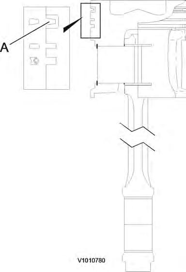
Cylinder head gasket, description
The cylinder head gasket is a multi layered gasket with 1, 2 or 3 identification holes to indicate three different thicknesses available. Selection of the proper thickness of gasket is determined by the measurement of piston projection above the cylinder block sealing surface. Recalibration for the correct gasket thickness would be required if new pistons or a new cylinder block were installed.
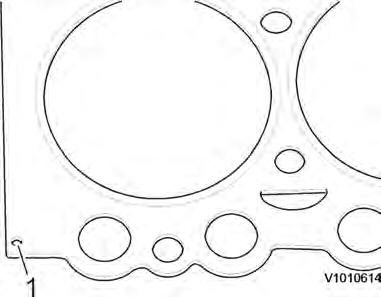
1
Document Title: Function Group: Information Type: Date:
Cylinder block, description 212 Service Information 2014/9/24
Profile: EXC, ECR305C L [GB]
Cylinder block, description
The cylinder block is cast in one piece and has wet, replaceable cylinder linings. Combustion pressure tensile breaking strength in cylinder head screws is led through stiffened sections of the cylinder block wall directly to the main bearings.
The cylinder block surface should not be ground as the distance between the pistons and the valve heads may become too small. There is also a risk that injector tips will be incorrectly placed in relation to the pistons and that exhaust values will worsen.
Document Title: Function Group: Information Type: Date:
Cylinder liner, description 213 Service Information 2014/9/24
Profile: EXC, ECR305C L [GB]
Cylinder
liner, description
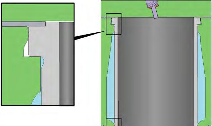
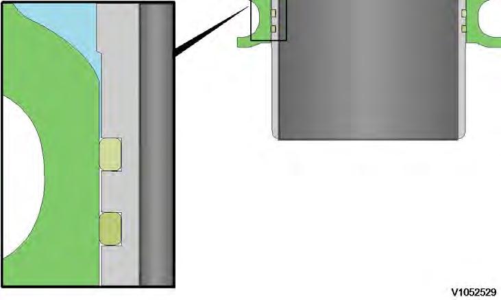
The engine has a cylinder block with wet (replaceable) cylinder liners. The bottom part of the liner is sealed against the cylinder block with two O-rings positioned in grooves machined into the lower end of the liner. The upper part of the cylinder liner is sealed by the cylinder head gasket and the pressure created by the cylinder head clamping force against liner protrusion.
Document Title: Function Group: Information Type: Date:
Pistons, description 213 Service Information 2014/9/24
Profile:
EXC, ECR305C L [GB]
Pistons, description
D6E Engine
The pistons are made of special alloy aluminium. The piston's combustion compartment has a somewhat off-center (eccentric) position in relation to the piston pin.
The pistons are provided with 3 piston rings. The first ring has a ring carrier made of cast iron. The piston is cooled with oil sprayed up on the inside of the piston top.
The piston cooling nozzles are made of plastic and are mounted in the cylinder head by the main bearing positions.
The first piston ring has an asymmetric cross-section area (A). The cross-section area for piston ring number two (compression ring) is tapered. When installing the piston rings, the marking TOP by the opening in the rings must face up. The third ring is an oil ring with bevelled edge.

Thank you so much for reading Download
If the above button click is invalid. Please download this document first, and then click the above link to download the complete manual.
Document Title: Function Group: Information Type: Date: Piston rings, description 213 Service Information 2014/9/24
Profile:
EXC, ECR305C L [GB]
Piston rings, description
Each piston is equipped with two compression rings and one oil ring. The uppermost compression ring is of the "Keystone" type (dual trapezoid-formed cross section). Compressions rings should be placed with the text facing upwards. The oil ring is equipped with two scraping edges, which are pressed against the cylinder wall using the spring tension in the ring and an expander spring placed on the inside of the ring. The oil ring can be placed on either side but should be placed with expander spring and oil ring openings 180° from one another.
