
Document Title: Function Group: Information Type: Date:
Engine, description (Deutz
D6D EOE2) 200
Profile:
EXC, EW145B [GB]
Go back to Index Page
Service Information 2014/4/27
Engine, description (Deutz D6D EOE2)
How much does a Volvo Ew145b weigh? olvo ew145b V manual
The engine is a 6–cylinder, 4–stroke, direct injected, turbocharged, aftercooled with a cast iron block and cylinder head. Gears in the engine gear case are hardened helical type for strength and reduced noise, arranged to provide quiet, smooth transmission of power.
The cylinder block and head are designed with internal passages forming galleries for both lubricating oil and coolant.
The fan belt is a poly type V-belt for improved performance and an auto tension adjuster maintains belt tension.
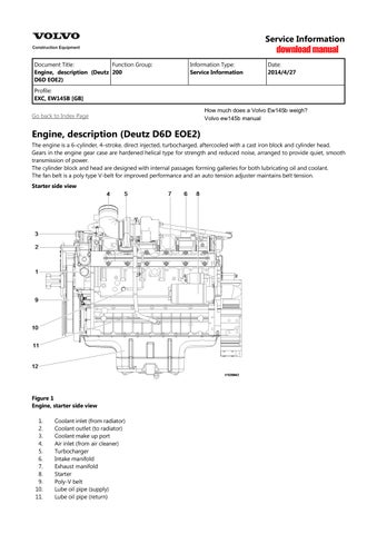
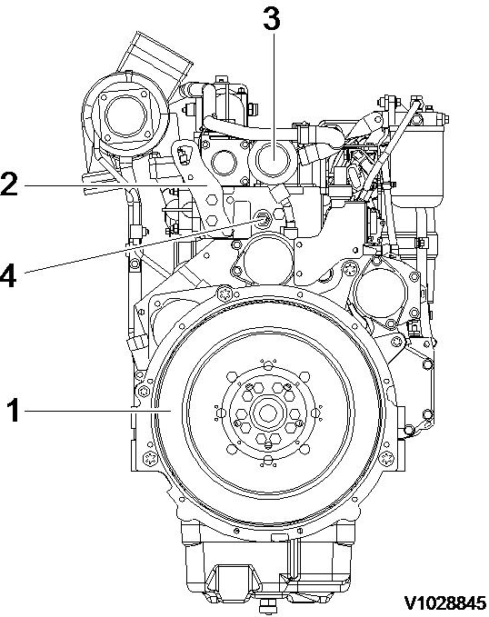
Starter side view
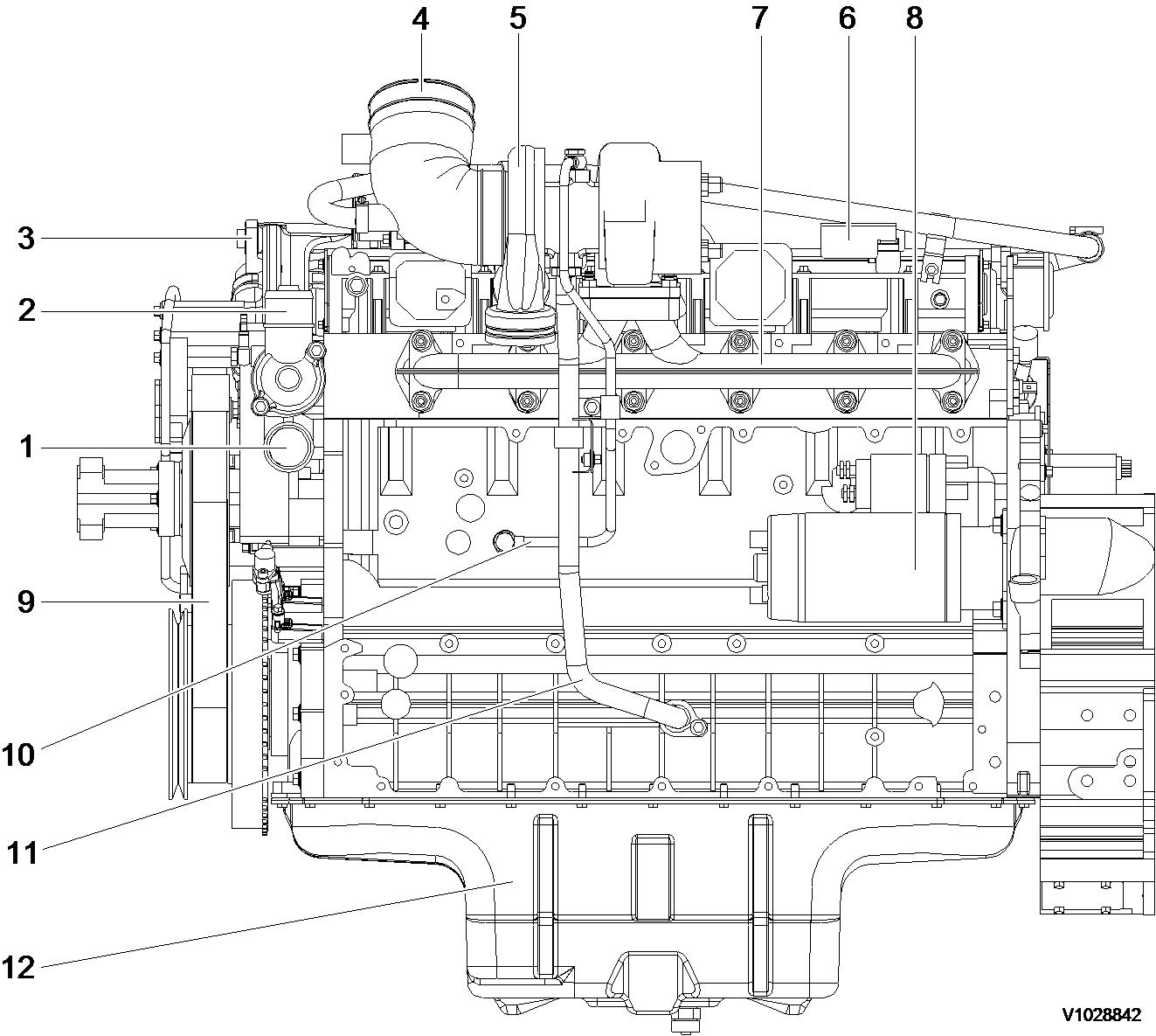
Figure 1 Engine, starter side view
Coolant inlet (from radiator)
Coolant outlet (to radiator)
Coolant make up port
Air inlet (from air cleaner)
Turbocharger
Intake manifold
Exhaust manifold
Starter
Poly-V belt
Lube oil pipe (supply)
Lube oil pipe (return)
Engine oil pan
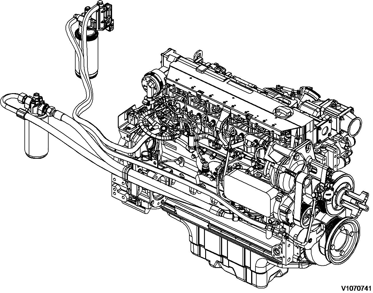
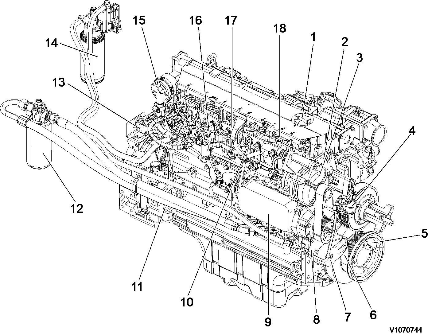
Engine, front side view
Air inlet (from charge air cooler)
Lifting eye (front)
Alternator
Fuel feed pump
Coolant pump
Belt tension
Air outlet (to charge air cooler)
Fan drive pulley
Air conditioner compressor pulley
Pulley with vibration damper
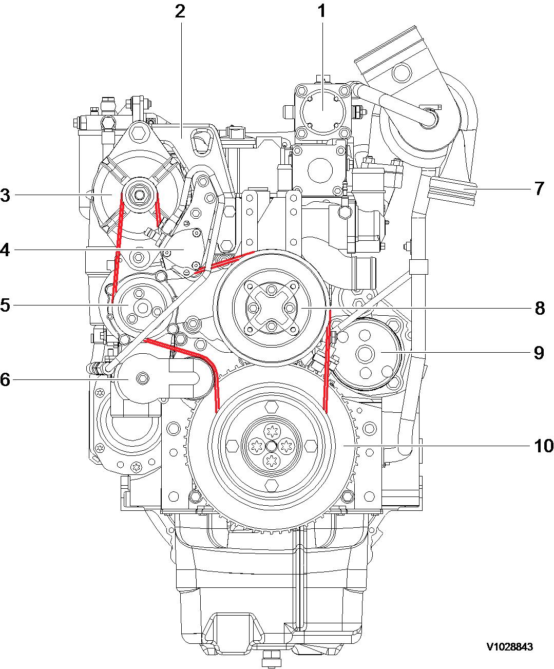
Engine, top side view
3
top side view
1
2
3
4
5
6
7
8
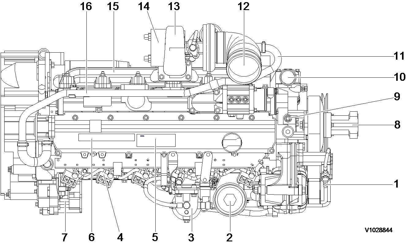
Engine, rear side view
Document Title: Function Group: Information Type: Date: Engine, description 200 Service Information 2014/4/27
Profile: EXC, EW145B [GB]
Go back to Index Page
Engine, description
D6E - tier 3 compliant
The D6E configuration is a four stroke, straight six cylinder, turbocharged, direct injected diesel engine with charge air cooling and wet, replaceable cylinder liners.
The D6E engine uses a Common Rail Fuel System controlled by the engine electronic control (E-ECU) software.
Electronically controlled IEGR (Internal Exhaust Gas Recirculation) reduces NO formation and lowers emissions without the need for exhaust after treatment. Volvo's latest engine management system, E-ECU is used to control all engine electronic functions.
The cylinders are numbered consecutively beginning at the flywheel end. Engine rotational direction is counterclockwise as seen from the flywheel end.
Document Title: Function Group: Information Type: Date:
Engine, tightening torques 200
Profile:
EXC, EW145B [GB]
Engine, tightening torques
NOTICE
Service Information 2014/4/27
Regarding bolted joints which are not listed here, see “Volvo standard tightening torques”
Engine, tightening torque
Rocker arm bracket on cylinder head
Cylinder head cover (M6) on cylinder head
Exhaust return module on cylinder head
Lock nut, valve adjusting screw
Locking screw on cylinder head
Solenoid valve on cylinder head
Front cover on crankcase
Drain plug on oil pan, M18
Crankcase ventilation on cylinder head
Return line to return stop valve
Return stop valve to crankcase
30 Nm (22.2 lbf ft)
13 Nm (9.6 lbf ft)
Step 1: 10 Nm (7.4 lbf ft)
Step 2: 30 Nm (22.2 lbf ft)
20 ±2 Nm (14.8 ±1.5 lbf ft)
34 Nm (25.2 lbf ft)
24 Nm (17.8 lbf ft)
Step 1: 3 Nm (2.2 lbf ft)
Step 2: 21 Nm (15.5 lbf ft)
55 Nm (40.7 lbf ft)
21 Nm (15.5 lbf ft)
30 Nm (22.2 lbf ft)
Nm (59.2 lbf ft)
Impulse transmitter (crankshaft) on holder on front cover 9 Nm (6.7 lbf ft)
Impulse transmitter (camshaft) on gearcase 9 Nm (6.7 lbf ft)
Turbocharger on exhaust manifold
42 Nm (31.1 lbf ft)
Clamping shoe injector on cylinder head 16 Nm (11.8 lbf ft)
Injection lines on rail and injector, high pressure line on high-pressure pump 25 Nm (18.5 lbf
Fuel supply pump on holder
Holder fuel supply pump on holder
V-belt pulley on fuel supply pump
Nm (20.0 lbf ft)
High pressure pump on crankcase, M10 Step 1: 10 Nm (7.4 lbf ft) Step 2: 50 Nm (37.0 lbf ft)
Fuel control valve
Fuel pipe on high pressure pump
Fuel pipe on control block
Rail on cylinder head
Pressure relief valve on rail
Rail pressure sensor on rail
Pipe clips, fuel line fastening
Fuel line on control block, fuel filter console and rail
Fuel pipe (return) on control block
Fuel pipe (return) on cylinder head
Fuel line on fuel filter8
Fuel filter console/radiator tank on crankcase
(74.0 lbf ft)
lbf ft)
(28.9 lbf ft)
Cover plate on cylinder cover, M6
Document Title: Function Group:
EXC, EW145B [GB]
Component locations
Component position, engine D6E. The following figures show the position of a number of components on engine D6E. Figure

2
Component locations, flywheel side
19 Crankcase bleeding valve
26 Turbocharger
20 Charge air manifold 27 Air outlet (to charge air cooler)Coolant inlet
21 Flywheel housing
22 Drain plug
Coolant inlet
Coolant outlet
23 Oil pan 30 Air inlet (from charge air cooler)
24 Starter motor
Exhaust manifold
25 Oil return line from turbocharger 32 Cylinder rocker arm cover
Document Title: Function Group: Information Type: Date: Engine characteristic curve 210 Service Information 2014/4/27
Profile: EXC, EW145B [GB]
Go back to Index Page
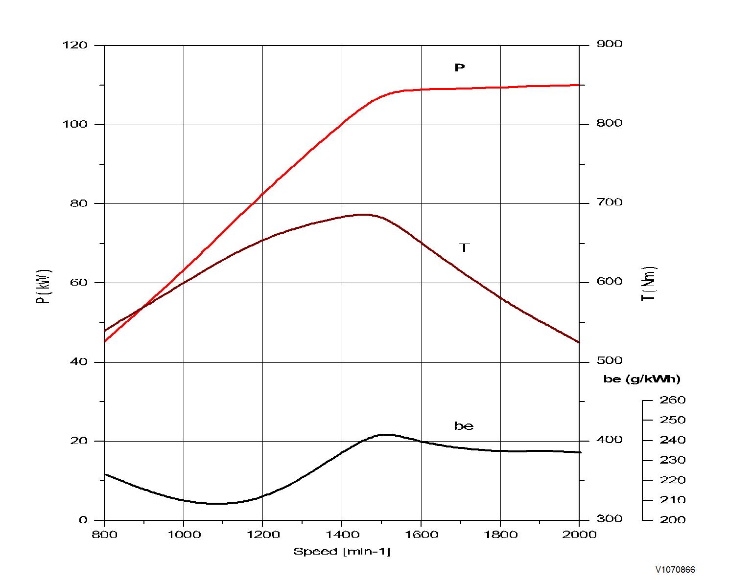
Engine characteristic curve
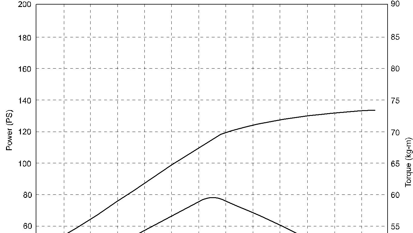
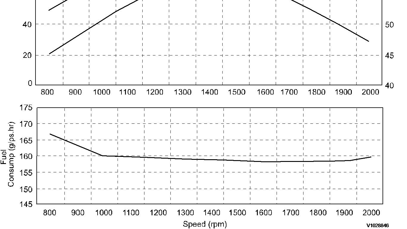
Engine, performance curve (power according to ISO 14396)
Document Title: Function Group: Information Type: Date:
Engine characteristic curve 210 Service Information 2014/4/27
Profile: EXC, EW145B [GB]
Go back to Index Page
Engine characteristic curve
1
Engine, performance curve (power according to ISO 14396)
Document Title: Function Group: Information Type: Date: Basic check, Engine 210 Service Information 2014/4/27
Profile:
EXC, EW145B [GB]
Basic check, Engine
Purpose of the basic check

WARNING
Certain tests and checks are performed with unlocked control lockout lever. Make sure that the machine cannot operate unexpectedly when the control lockout lever is unlocked.
The purpose of the basic check is to provide fast and accurate information about the general condition of the engine.
The basic check should be performed and evaluated according to instructions in the PC-tool VCADS Pro.
Tests included in the basic check
The basic check which is divided into the following tests should be performed after reading out error codes and checking parameters
Tests:
Cylinder compression, test
The purpose of the test is to show if any cylinder has a deviating compression pressure. The test replaces the old pressure check method but does not give any absolute values.
Cylinder balancing, test
The purpose of the test is to show if there is any deviation in the fuel injection to a cylinder.
Feed pressure, test
The purpose of the test is to check that the feed pressure is as per specification.
Sensor, test
The purpose of the test is to check the function of all sensors.
Document Title: Function Group: Information Type: Date:
Cylinder head, description 211 Service Information 2014/4/27
Profile: EXC, EW145B [GB]
Go back to Index Page
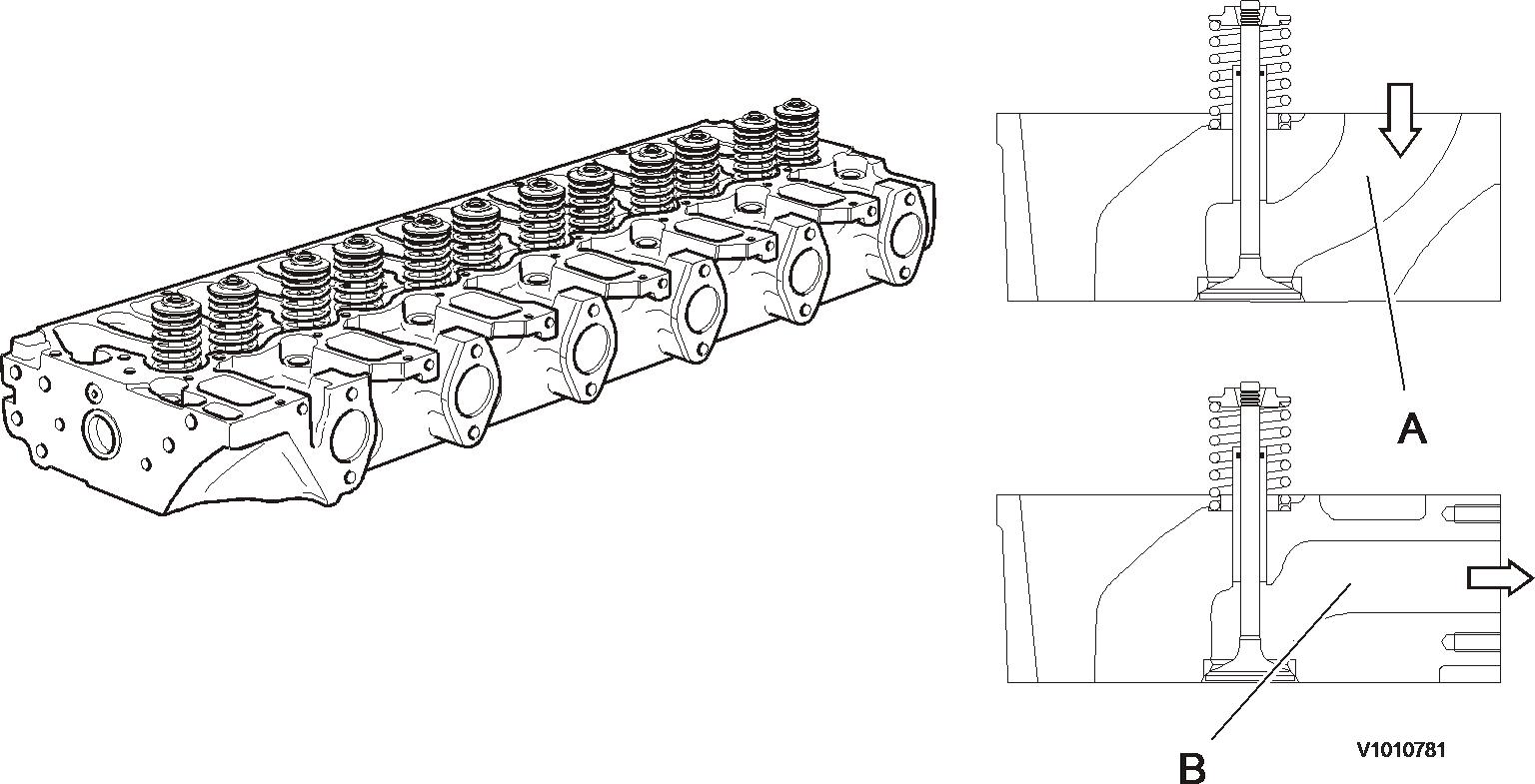
Cylinder head, description
The cylinder head of the D6D engine is made of grey cast iron and designed as block type head. The combustion air enters vertically and the exhaust air is discharged laterally. Inlet and outlet are located on one side of the cylinder head.
Document Title: Function Group: Information Type: Date:
Cylinder head, description 211 Service Information 2014/4/27
Profile:
EXC, EW145B [GB]
Go back to Index Page
Cylinder head, description
The cylinder head is made of grey cast iron and is common for all cylinders. The induction air enters vertically (A) and the exhausts leave horizontally (B). Inlets and exhaust outlets are located on the same side of the cylinder block. Inlet and exhaust valve size is increased to optimize the gas exchange and combustion process. Valve guides are replaceable. Coolant flow in the cylinder head is modified to accommodate an outlet controlled cooling system. On order for the engine to fulfill governing emission standards, there are 3 cylinder head gaskets of different thicknesses between the cylinder head and the piston.
Document Title: Function Group: Information Type: Date:
Determining cylinder head gasket 211 Service Information 2014/4/27
Profile:
EXC, EW145B [GB]
Determining cylinder head gasket
The thickness of the cylinder head gasket is responsible for the correct piston crown clearance of the engine. The piston crown clearance (0.65 mm) essentially influences the combustion and thus:
Power Fuel consumption Exhaust emission
The piston crown clearance is adjusted by determining the piston projection and the thickness of the cylinder head gasket.
Measuring piston projection
A dial gauge with a fixture is needed to measure the piston projection. The piston is in its TDC position above the cylinder blackface.
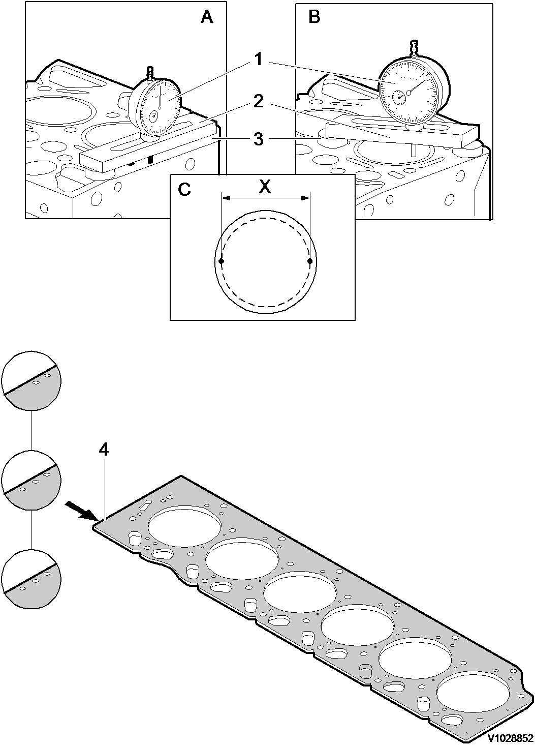
1. 2. 3. Dial gauge Bridge
Two spacer plates A. B. C.
Set the dial gauge on the level of the cylinder block face to “zero”. Position the dial gauge at measuring points (C), at the piston pin axis on the piston and determine the maximum projection. Measuring points on the piston.
Distance X = 90 mm
This measurement is performed on each piston. The maximum measured piston projection determines the thickness of the cylinder head gasket (see table). There are 3 different gasket thicknesses identified by bores (4):
1 bore = 1.2 mm
2 bores = 1.3 mm
3 bores = 1.4 mm
Piston projection
Piston projection
Identification of cylinder head gasket
0.33 ~ 0.55 mm 1 bore
0.56 ~ 0.65 mm 2 bores
0.66 ~ 0.76 mm 3 bores
Document Title: Function Group: Information Type: Date:
Fitting cylinder head 211 Service Information 2014/4/27
Profile:
EXC, EW145B [GB]
Fitting cylinder head
Op nbr 21182
1. Prior to fitting the cylinder head onto the crankcase, the sealing surfaces for the cylinder head gasket must be clean and free from oil. Pay attention to dowel sleeves.
2. Lightly oil the cylinder head bolts.
3. It is absolutely necessary to observe the bolt tightening order in the adjacent schematic.
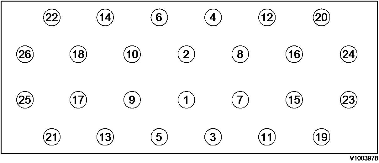
Figure 1
Tightening order (exhaust manifold side)
Tightening torque specification:
1st step: 30 N·m (22.2 lbf·ft, 3.1 kgf·m)
2nd step: 80 N·m (59 lbf·ft, 8.2 kgf·m)
3rd step: 90° turn
Tightening order

Thank you so much for reading Download
If the above button click is invalid. Please download this document first, and then click the above link to download the complete manual.
Document Title: Function Group: Information Type: Date:
Cylinder, description 213 Service Information 2014/4/27
Profile: EXC, EW145B [GB]
Cylinder, description

Figure 1
Cylinder liner
1 Cylinder liner
2 Crankcase
3 Liner projection: 0.07 - 0.12 mm
D6D/D6E engine with a bore about 98 mm (3.86 in) is provided with dry, plateau-honed slip-fit cylinder liners. In case of damage, the cylinders of the D6D/D6E series are repaired by replacing the slip-fit liners.