
Document Title: Function Group: Information Type: Date:
Engine characteristic curve (Cummins B5.9-C) 210 Service Information 2014/5/31
Profile:
Engine characteristic curve (Cummins B5.9-C)
Engine characteristics
Item
Rated output
Max. torque (Net)
Min. fuel consumption
145 PS/1900 rpm (143 HP/1900 rpm)
63 kgf·m/1500 rpm (455 lbf·ft/1500 rpm)
151g / PS·h
Rated fuel consumption 158g / PS·h
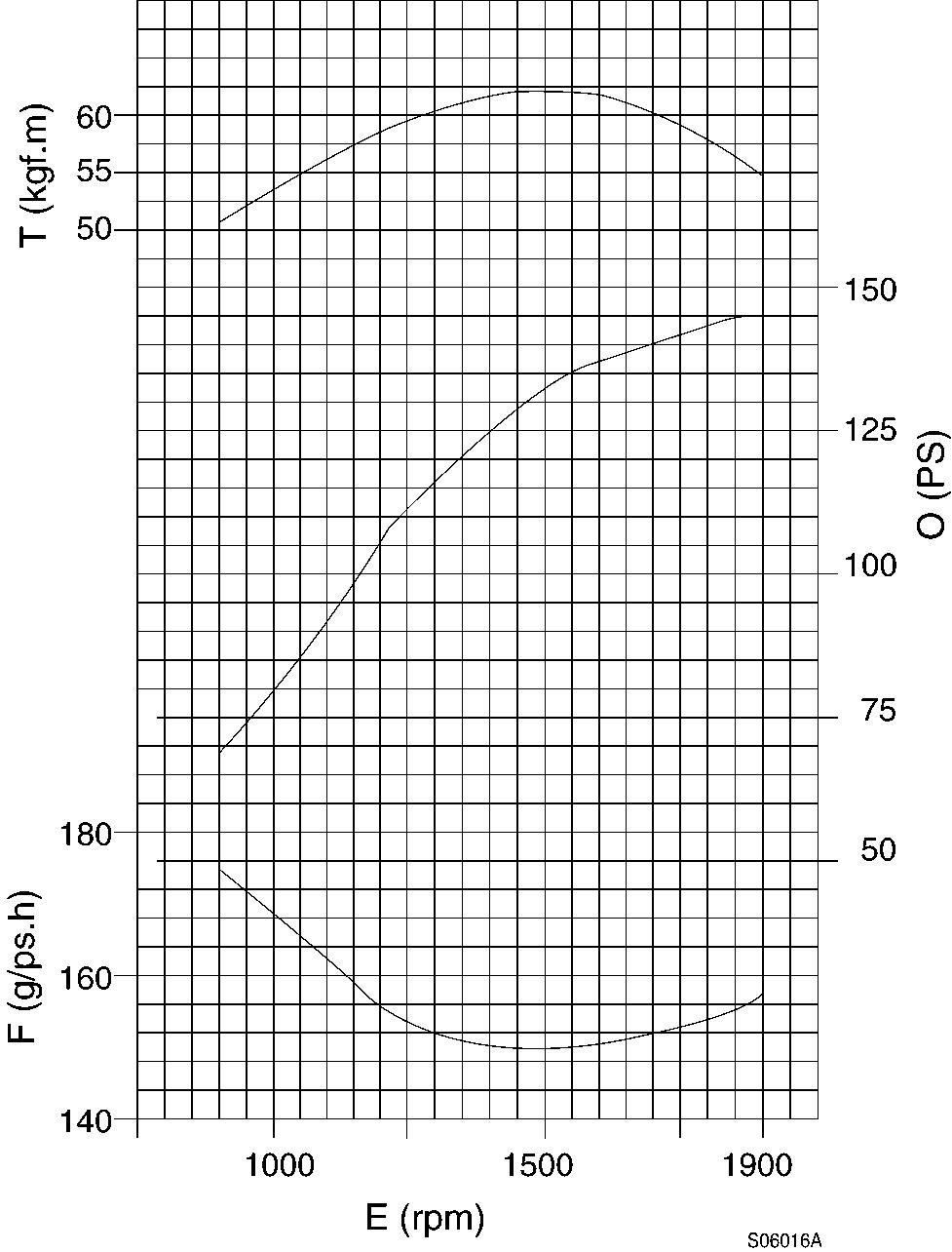
Figure 1
Engine, characteristic curve
T. Torque
F. Fuel consumption
O. Output
E. Engine speed download manual

Document Title: Function Group: Information Type: Date: Engine, description (Cummins B5.9-C) 210
Service Information 2014/5/31
Profile:
Engine, description (Cummins B5.9-C)
The engine is a 6-cylinder, 4-stroke, direct injected, turbocharged, aftercooled, water cooled assembly with a cast iron block and cylinder head.
Gears in the engine gear case are hardened helical type for strength and reduced noise, arranged to provide quiet, smooth transmission of power.
The cylinder block and head are designed with internal passages formed as sets for lubrication and cooling. The water pump and oil cooler are integrally mounted.
The fan belt is a poly type V-belt for improved performance and an auto tension adjuster maintains belt tension.
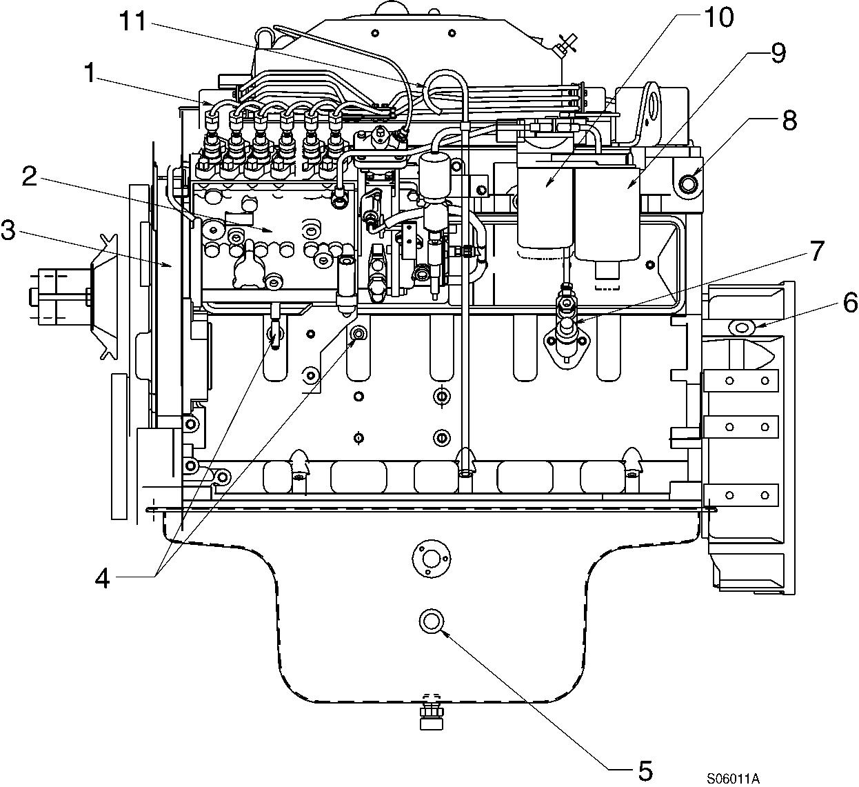
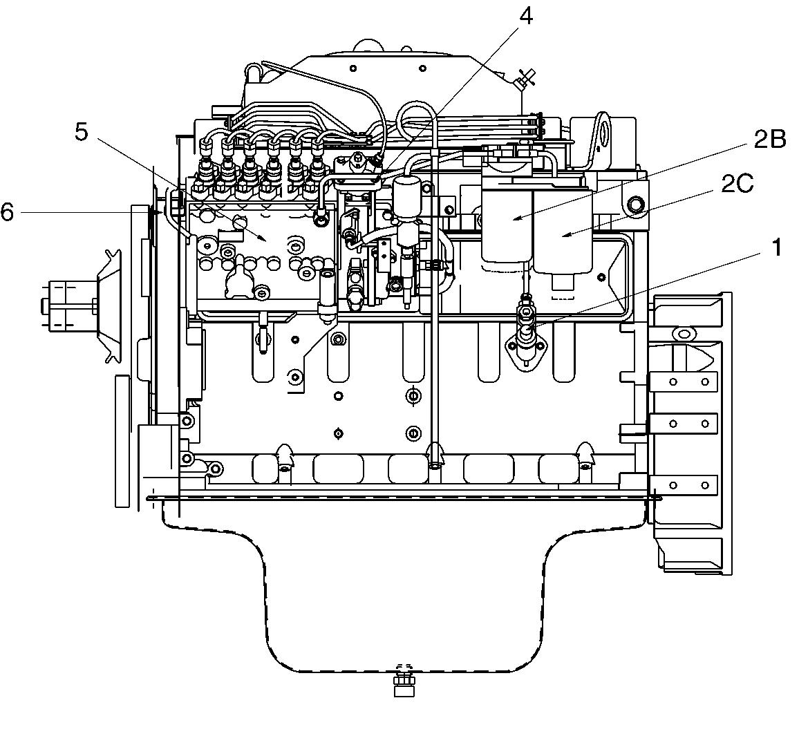
High pressure fuel line
Fuel injection pump
Engine data plate
Engine oil pressure sensor port (1/8″ NPTF)
Engine oil heater port (M22 × 1.5P)
Engine speed sensor port (3/4″-16 UNF)
Fuel feed pump
Water temperature sensor port (3/4″ NPTF)
Primary fuel filter/water separator
Secondary fuel filter
Dipstick
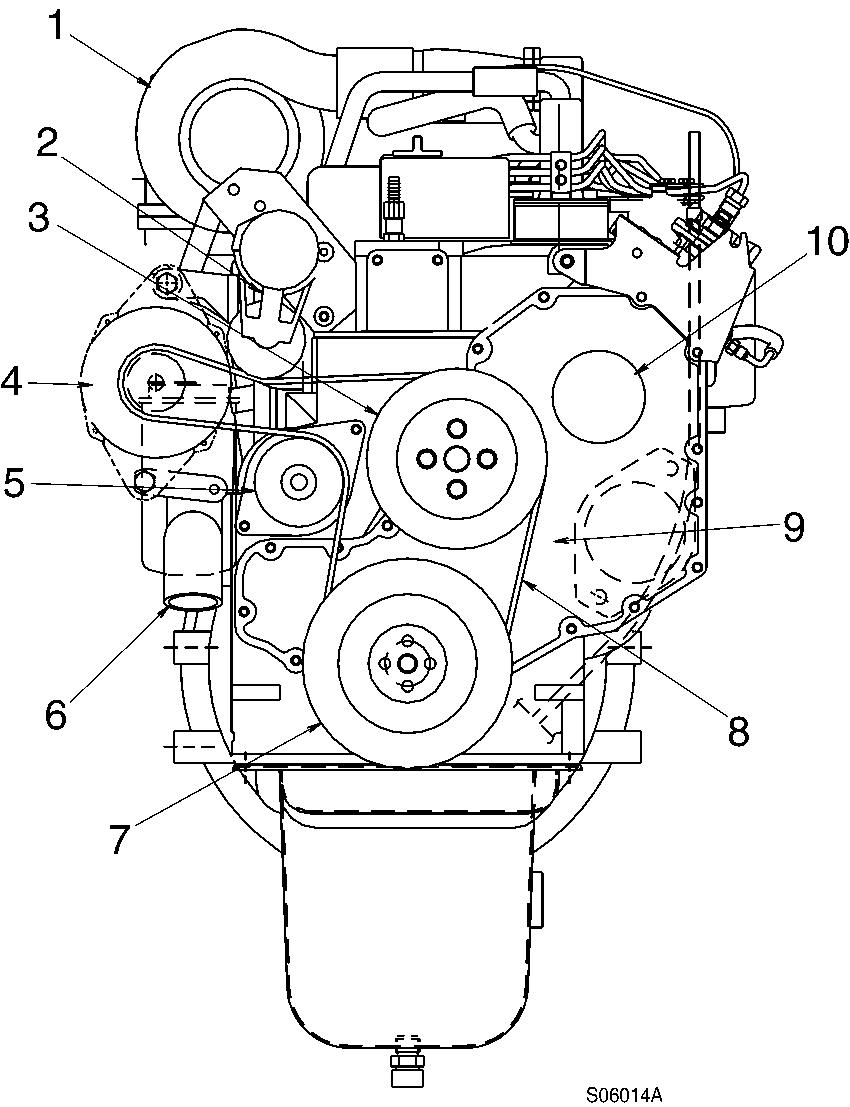
2 Engine, turbocharger side view
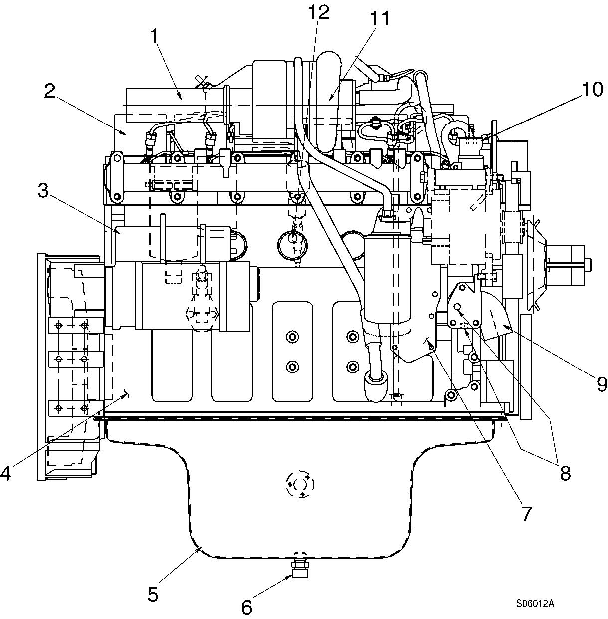
Exhaust gas discharge port
Valve cover Starter
Engine block Oil pan
Engine oil drain valve (M22 × 1.5P)
Engine oil cooler
Water temperature switch port (PT 1/2″)
Water inlet
Thermostat
Turbocharger
Block heater port
Engine oil refill plug
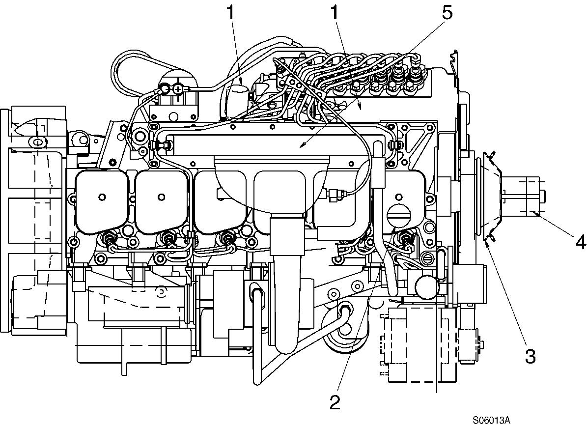
Fan drive and pulley
Fan spacer Aftercooler
Turbocharger Automatic belt tensioner
Fan pulley Alternator
Water pump
Water inlet
Vibration damper
Fan belt
Gear cover
Fuel injection pump gear cover
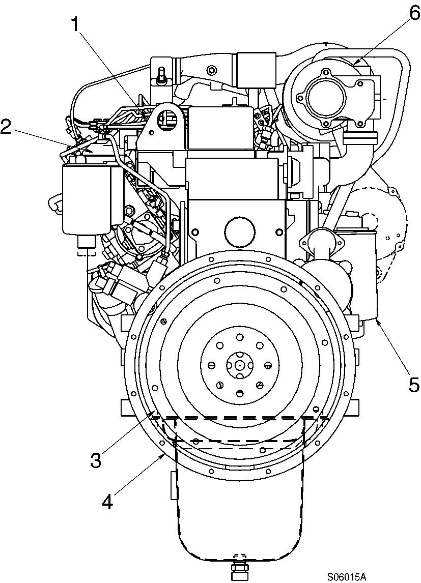
Engine lifting eye
Flywheel
Flywheel housing
Engine oil filter
Turbocharger
Document Title: Function Group: Information Type: Date:
Valve clearance adjustment 214 Service Information 2014/5/12
Profile:
Valve clearance adjustment
Cummins B5.9-C
Valves must be correctly adjusted for the engine to operate efficiently. Valve adjustment must be performed using the specified values.
Adjust the valves at each 1000 hours or 1 year maintenance interval.
All the valve adjustments must be made when the engine is cold and stabilized coolant temperature is 60°C or below.
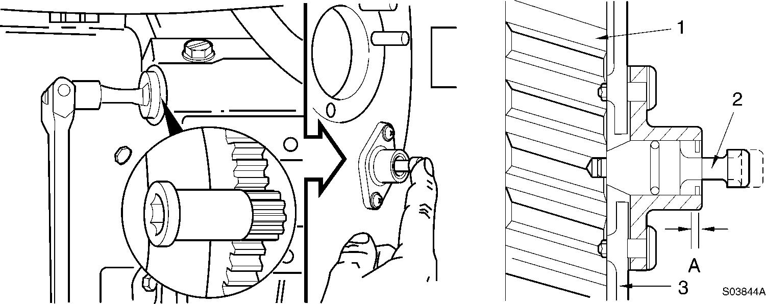
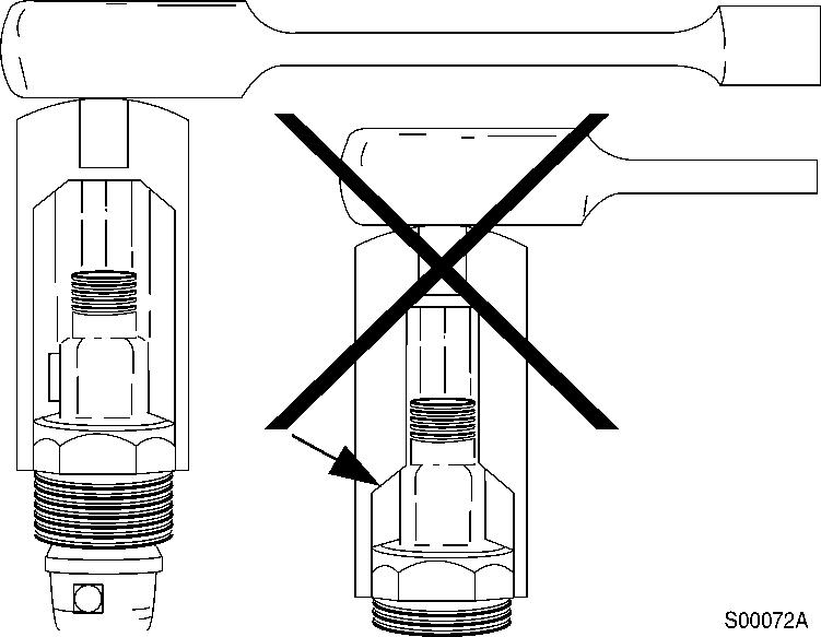
Turn the valve adjustment screws in until touching the push rod sockets, and then loosen them one full turn. Use 1/2″ drive, Part No. 3377371 Engine Barring Tool.
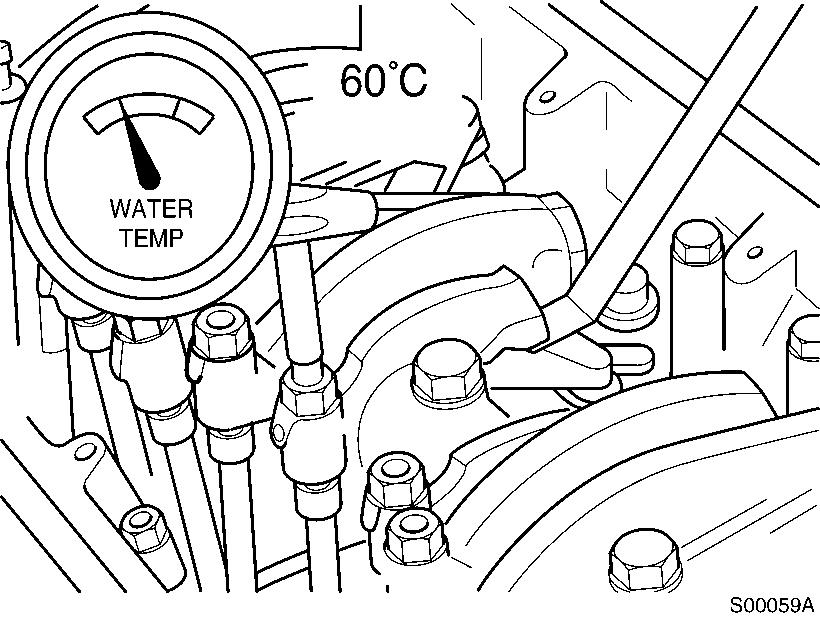
Locate top dead center for cylinder No.1 by rotating the crankshaft slowly while pressing on the engine timing pin. When the pin engages the hole in the camshaft gear, cylinder No.1 is at top dead center on the compression stroke.
3
Rotation, camshaft gear
Camshaft gear
Timing pin
Gear housing
A. Compression stroke

CAUTION
Disengage the timing pin. Engine components may be damaged if the engine is rotated with the timing pin engaged.
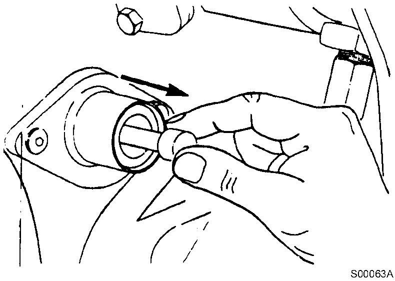
Figure 4
Removal, timing pin
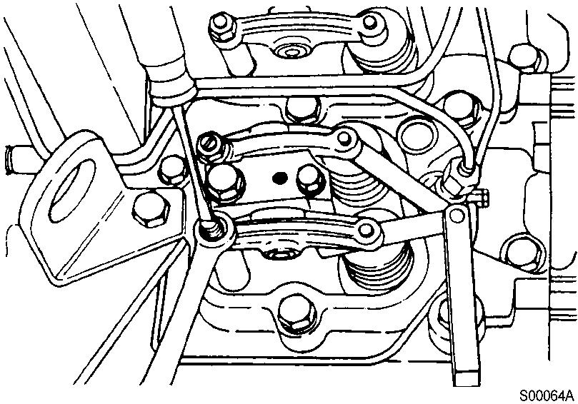
Figure 5
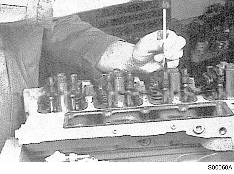
Adjustment, clearance between the valve stem and rocker lever
Tools : 14 mm spanner, “-” screwdriver, feeler gauge.
The clearance is correct when slight resistance is felt as the feeler gauge is moved between the valve stem and rocker lever. At that point, tighten the lock nut. (Tightening torque : 24 N·m)
Adjust the valves indicated (*) in the table below.
After tightening the lock nut, check the valve clearance again. If the clearance is not correct, readjust.
Valves to be adjusted (*)
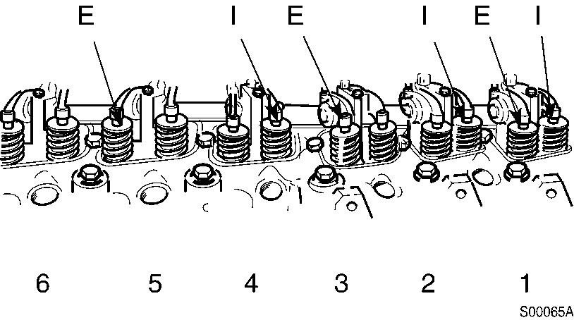
Figure 6
Valves to be adjusted
CAUTION
Be sure the timing pin is disengaged.
NOTE!
Mark the crankpulley and cover.
NOTE!
Rotate the crankshaft 360°.
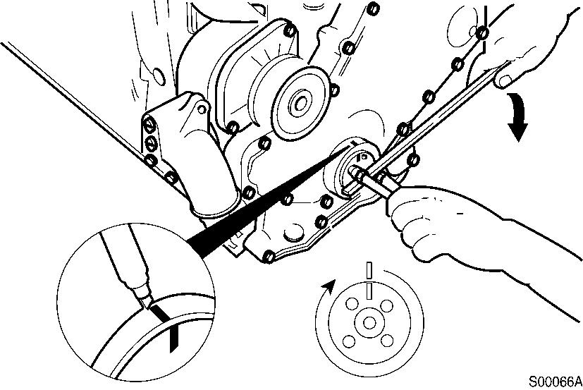
Figure 7
Marking, crankpulley
Adjust the valves indicated (*) in the table below.
After tightening the lock nut, check the valve clearance again. If the clearance is not correct, readjust.
Valves to be adjusted (*)
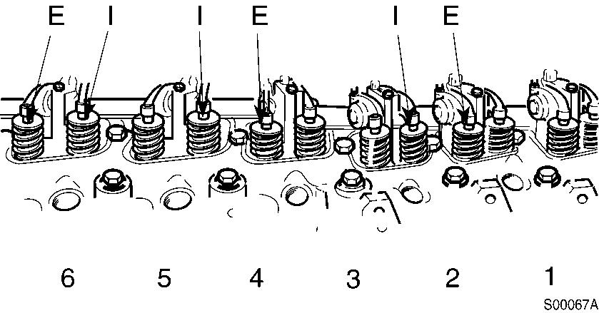
Figure 8
Valves to be adjusted
Assemble the gaskets, valve covers, o-rings and special screws.
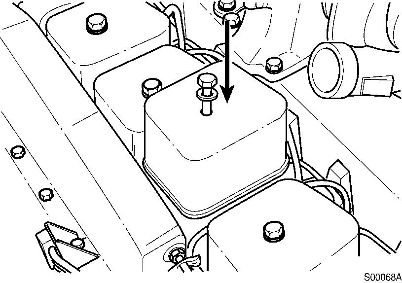
Figure 9
Assembly, valve covers
Tools : 16 mm spanner
Tightening torque : 24 N·m (18 lbf·ft)
NOTE!
Check valve covers and o-rings. If damaged, replace with a new one.
Injection nozzles installation
Assemble a sealing washer on each injection nozzle. Use only one sealing washer.
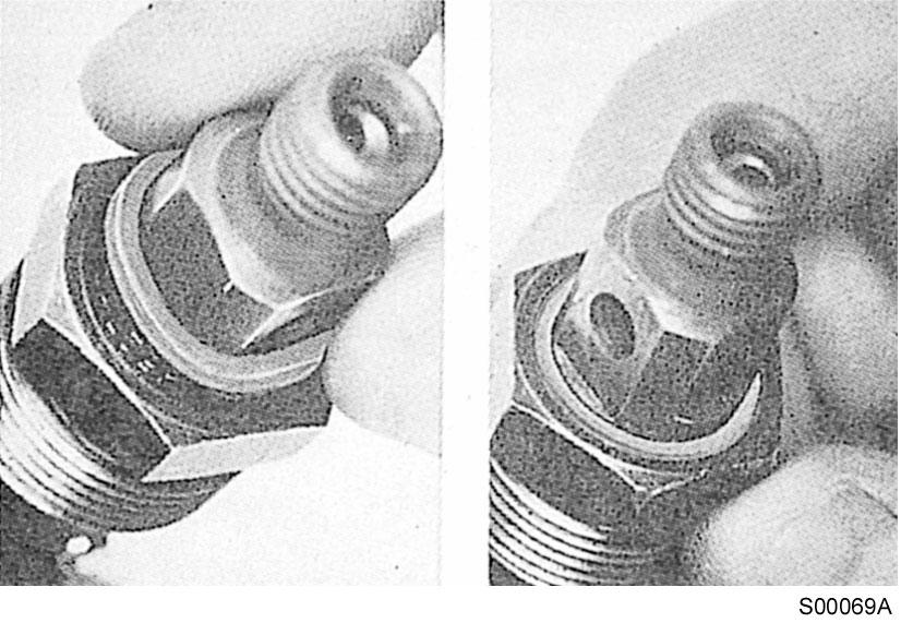
10
Assembly, injection nozzles
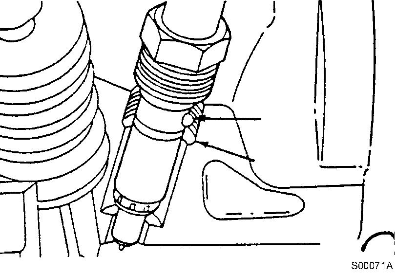
Apply anti-seize compound to the threads of the injector hold-down nut and between the top of the nut and injector body.

11
Apply, anti-seize compound
12
Installation, injection nozzle
Tools : 16 mm spanner, 24 mm Deep socket
Tightening torque : 60 N·m (44 lbf·ft)
NOTE!
Install the injection nozzle. The protrusion on the injector body fits into a notch in the cylinder head to position the injector. Tighten the injection nozzle nuts.
13
Tightening, injection nozzle
NOTE!
Some sockets can damage the sealing surface of the fuel drain outlet.
Document Title: Function Group: Information Type: Date:
Engine mounting 218 Service Information 2014/5/12
Profile:
Engine mounting
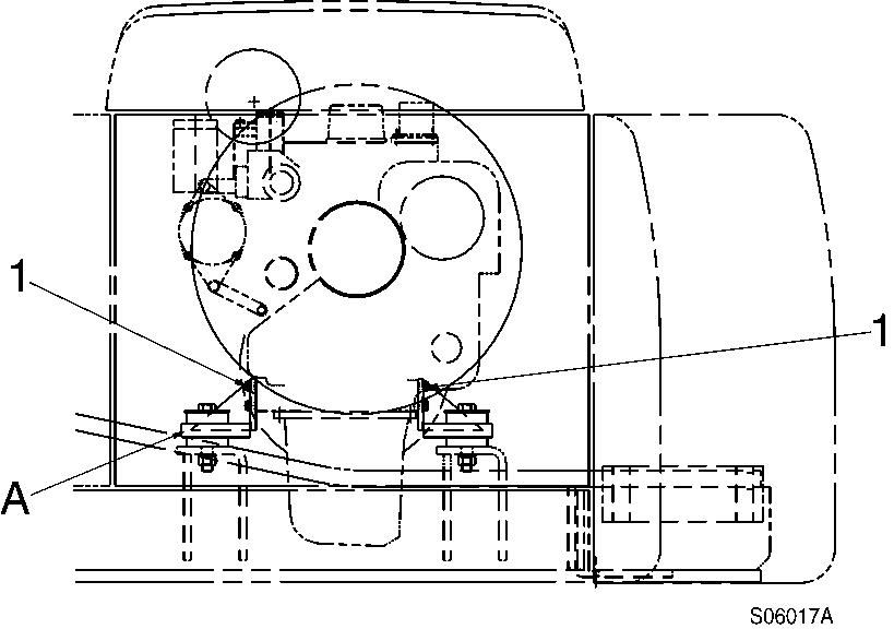
1
Engine mounting, front-fan side view
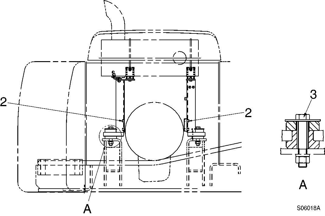
Figure 2
Engine mounting, rear-flywheel side view
A. A-details (cushion)
NOTE!
Check the color markings for cushion installation.
Cushion (A-details)
Front (fan side) - Yellow and white
Rear (flywheel side) - Blue and white
Tightening torque, unit : kgf·m (lbf·ft)
No. Mounting position
1 Engine mounting bracket (front) * Apply loctite # 243
2 Engine mounting bracket (rear)
Tightening torque
M12 × 1.75 × 35L (4)
M12 × 1.75 × 65L (2)
11 ~ 12 (80 ~ 87)
M12 × 1.75 × 50L
* Apply loctite # 243
3 Engine mounting cushion
7.2 ~ 8.4 (52 ~ 61)
M22 × 2.5 × 130L
69.4 ± 6.9 (501 ± 50)
Document Title: Function Group: Information Type: Date: Lubricating system, description 220 Service Information 2014/5/31
Profile:
Lubricating system, description
Engine lubricating oil is supplied to the contact faces of rotating components such as turbocharger, crankshaft, camshaft, piston, inlet/exhaust valve, rocker arm and timing gear by means of forced lubrication from the oil pump.
Lubricating oil flow diagram
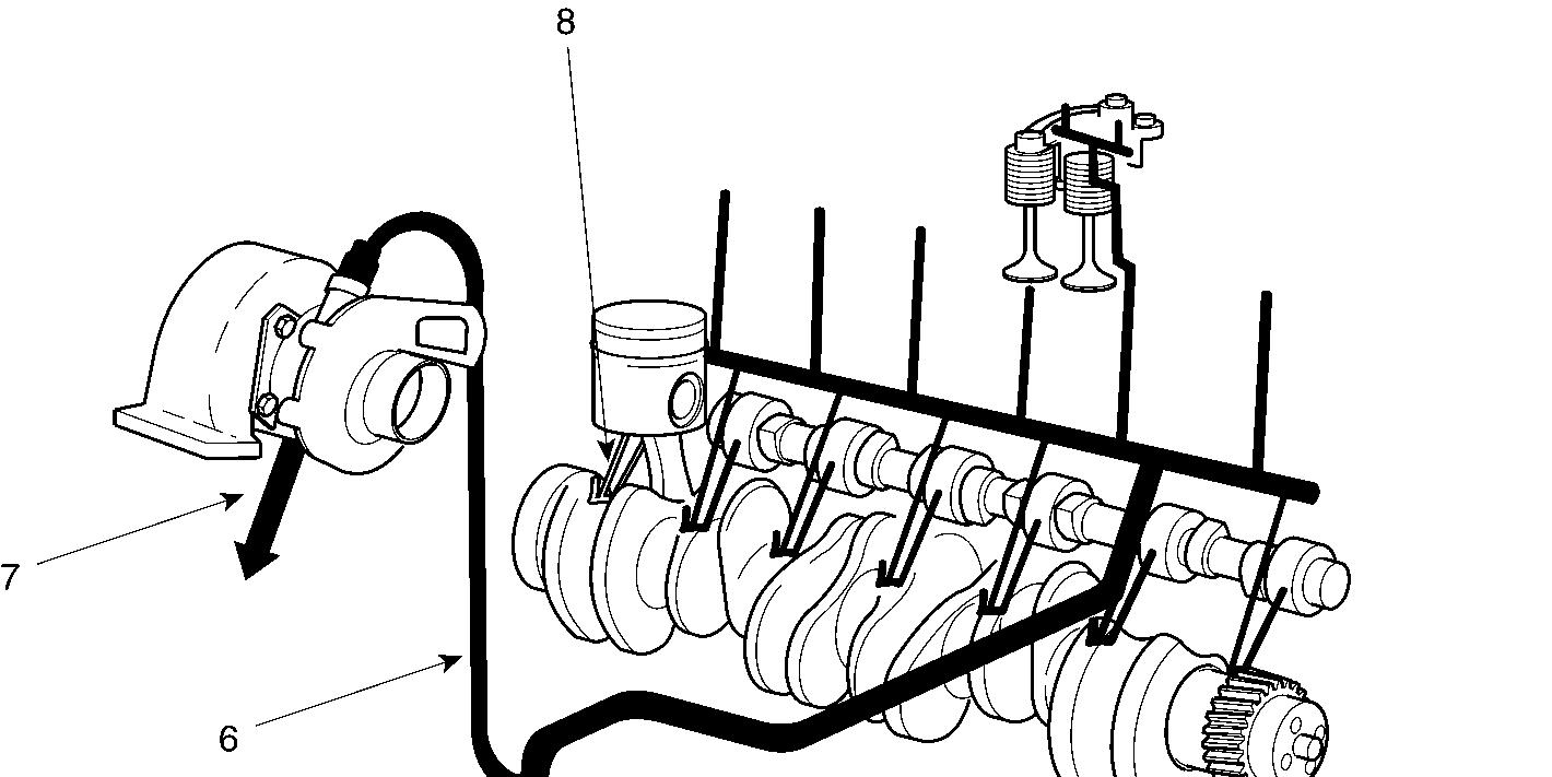
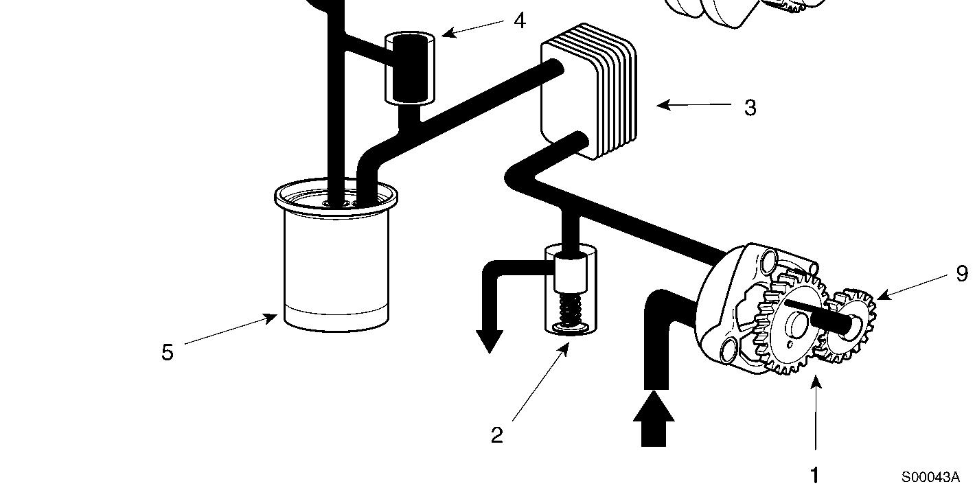
Oil pump
Pressure regulating valve
Oil cooler
Filter bypass valve
Oil filter
Turbocharger oil supply
Turbocharger to oil pan
Piston cooling nozzle
Oil pump idler gear
Document Title: Function Group: Information Type: Date: Fuel injection system (Cummins B5.9-C) 230 Service Information 2014/5/31
Profile:
Fuel injection system (Cummins B5.9-C)
Highly pressurized fuel compressed by the fuel pump is direct injected through the injection nozzle into the combustion chamber.
Remaining fuel after injection is returned to tank automatically.
A water separator installed to protect the fuel system components provides a means to drain off the water and contaminants collected from the system.
Fuel flow system diagram
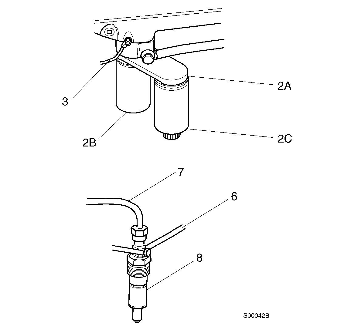
Bleed screw
Low pressure supply line
Fuel injection pump
Fuel drain line
High pressure fuel supply line
Fuel injection nozzle
Document Title: Function Group: Information Type: Date: Fuel tank, description 2341 Service Information 2014/5/12
Profile:
Fuel tank, description
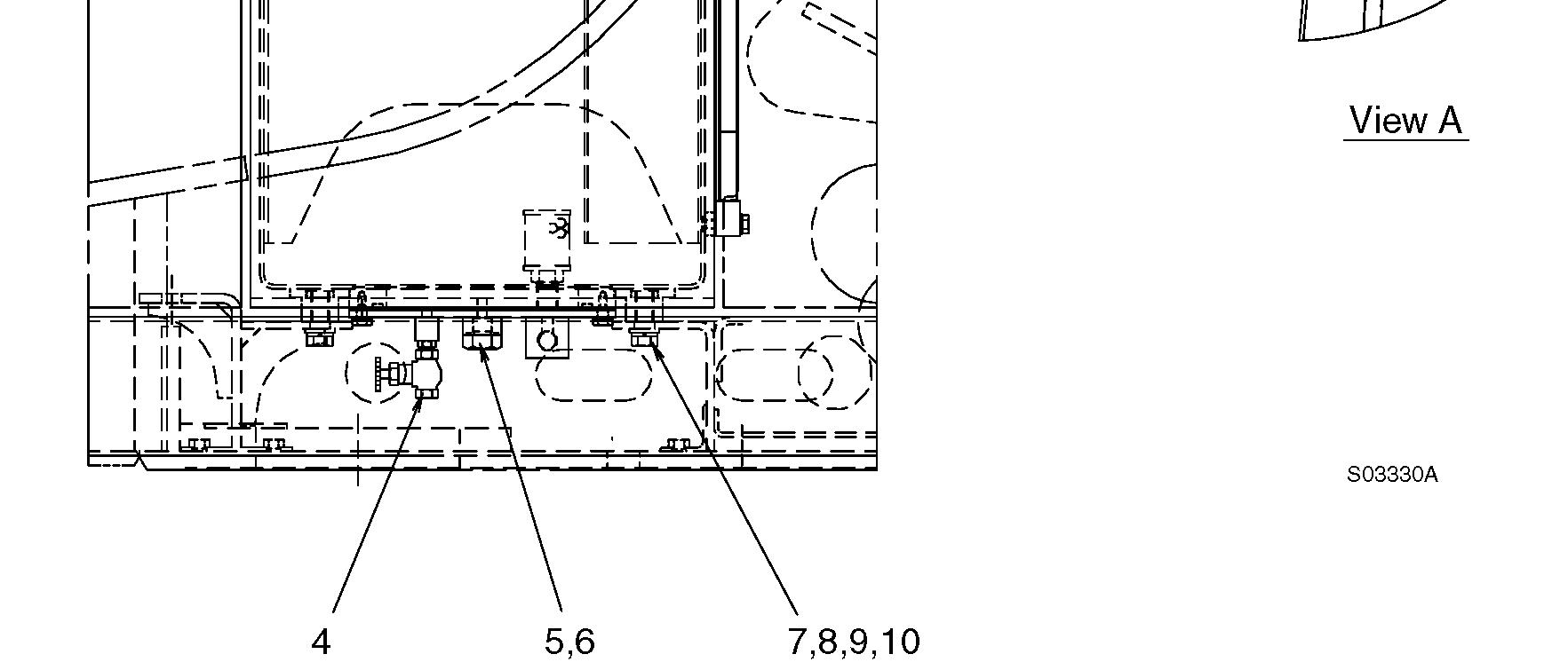
Figure 1
Structure, fuel tank
1 Tank 7 Screw
2 Cap 8 Plain washer
3 Screen filter 9 Spring washer
4 Drain cock 10 Shim
5 Plug 11 Level gauge
6 O-ring
When mounting the tank, adjust the height by use of shim (10).
Tightening torque :
Screw (7) : 52.2 ± 5.2 kgf·m (377 ± 38 lbf·ft)
Hydraulic tank
Tool box
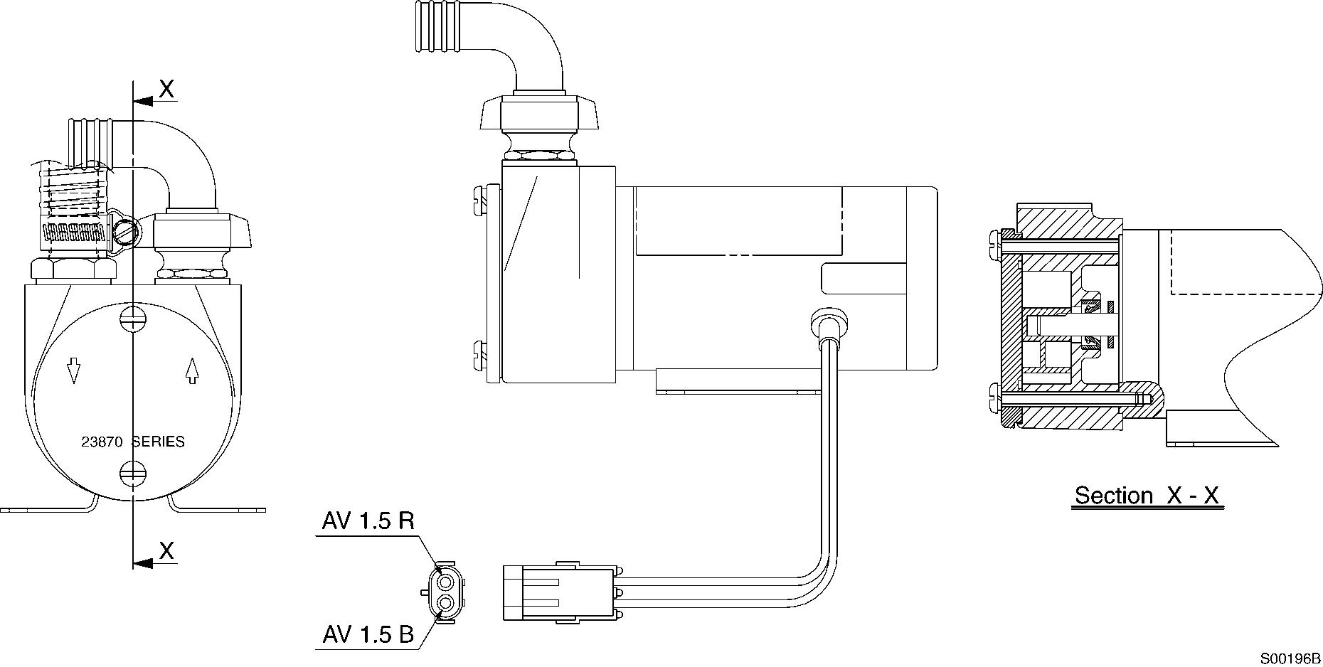
Document Title: Function Group: Information Type: Date: Fuel filler pump, description 2344 Service Information 2014/5/12
Profile:
Fuel filler pump, description
The pump outlet is plumbed directly to the fuel tank to reduce the risk of introducing contamination. The master switch must be in the ON position to operate the fuel filler pump.
CAUTION
The filter at the end of fuel filler pump inlet hose is a strainer, and will not filter impurities from the fuel. When filling use CLEAN fuel only!
CAUTION
Do not operate the fuel filler pump without fuel or for extended periods of time.
CAUTION
Drain the fuel from the suction hose before putting it in the storage compartment.
CAUTION
In case the pump has been disassembled, assemble the pump so the that the sharp portion of the vane faces the counterclockwise direction.
Document Title: Function Group: Information Type: Date: Fuel warmer, description 2349 Service Information 2014/5/12
Profile:
Fuel warmer, description
The fuel warmer function is to prevent filter and line blockage by melting the paraffin wax extracted from the diesel fuel in severe cold weather. If the fuel warmer switch on the switch board is ON, the warning lamp on the monitor panel is activated.
CAUTION
After starting the engine, be sure to turn the fuel warmer switch to the OFF position.
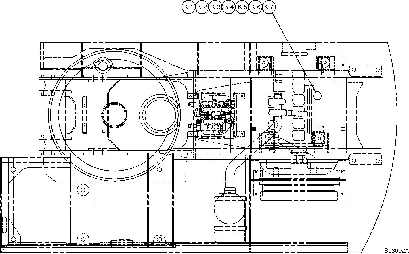
After removing the fuel secondary filter, install the fuel warmer assembly (K-1 ~ K-7). Assemble the wire K-2 to the connector EN28-F in the engine compartment.
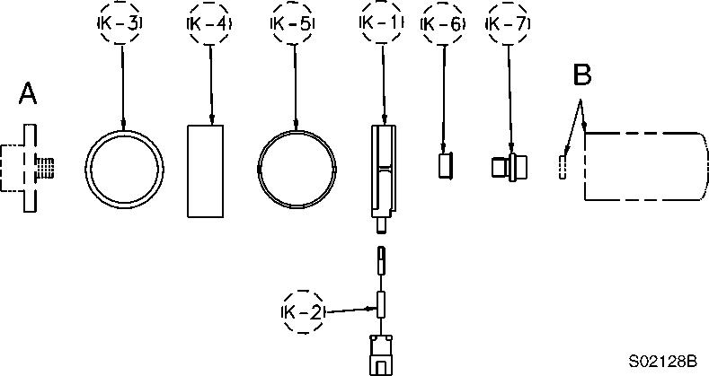
B. Filter head Fuel filter
K-1. Fuel warmer
K-2. Wires
K-3. Gasket
K-4. Adapter
K-5. O-ring
K-6. Insulator
K-7. Center post
Component location

Suggest:
If the above button click is invalid.
Please download this document first, and then click the above link to download the complete manual.
Thank you so much for reading
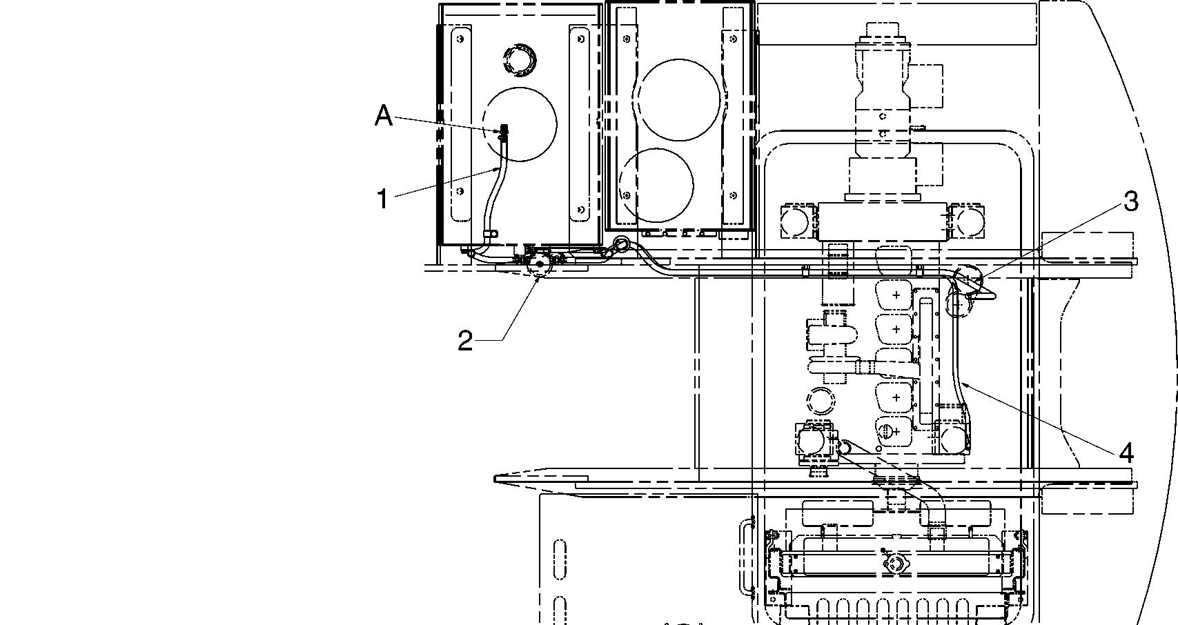
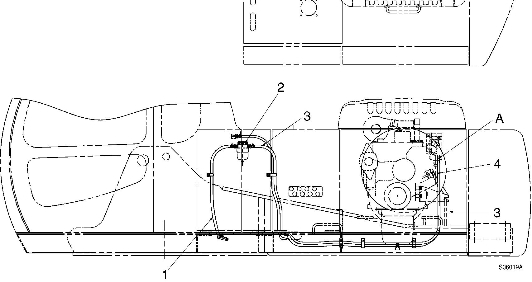
Document Title: Function Group: Information Type: Date: Fuel lines, description 235 Service Information 2014/5/12
Profile:
Fuel lines, description
The fuel level sensor is installed in the fuel tank.
When the fuel level gauge indicates EMPTY, there is still approximately 40Liter remaining.
Fuel flow