


This Workshop Manual has been prepared to provide servicing personnel with information on the mechanism, service and maintenance of KUBOTA Tractors M6800, M6800S, M8200 and M9000. It is divided into two parts, “Mechanism” and “Servicing” for each section except “ENGINE” section.
■ Mechanism
Information on the constructuion and function are included. This part should be understood before proceeding with troubleshooting, disassembling and servicing.
■ Servicing
Under the heading “General” section comes general precautions, check and maintenance and special tools. Other section, there are troubleshooting, servicing specification lists, checking and adjusting, disassembling and assembling, and servicing which cover procedures, precautions, factory specifications and allowable limits.
All information illustrations and specifications contained in this manual are based on the latest product information available at the time of publication.
The right is reserved to make changes in all information at any time without notice.
August 2001
0 KUBOTA Corporation 2001
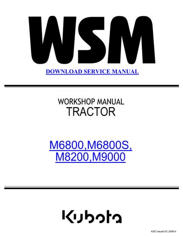
This symbol, the industry's “Safety Alert Symbol”, is used throughout this manual and on labels on the machine itself to warn of the possibility of personal injury. Read these instructions carefully. It is essential that you read the instructions and safety regulations before you attempt to repair or use this unit.
DANGER : Indicates an imminently hazardous situation which, if not avoided, will result in death or serious injury.
WARNING : Indicates a potentially hazardous situation which, if not avoided, could result in death or serious injury.
CAUTION : Indicates a potentially hazardous situation which, if not avoided, may result in minor or moderate injury.
■ IMPORTANT : Indicates that equipment or property damage could result if instructions are not followed.
■ NOTE : Gives helpful information.
• Read all instructions and safety instructions in this manual and on your machine safety decals.
• Clean the work area and machine.
• Park the machine on a firm and level ground, and set the parking brake.
• Lower the implement to the ground.
• Stop the engine, and remove the key.
• Disconnect the battery negative cable.
• Hang a “DO NOT OPERATE” tag in operator station.
• Do not start the engine by shorting across starter terminals or bypassing the safety start switch.
• Do not alter or remove any part of machine safety system.
• Before starting the engine, make sure that all shift levers are in neutral positions or in disengaged positions.
• Never start the engine while standing on ground. Start the engine only from operator's seat.
• Do not work on the machine while under the influence of alcohol, medication, or other substances or while fatigued.
• Wear close fitting clothing and safety equipment appropriate to the job.


• Use tools appropriate to the work. Makeshift tools, parts, and procedures are not recommended.
• When servicing is performed together by two or more persons, take care to perform all work safely.
• Do not work under the machine that is supported solely by a jack. Always support the machine by safety stands.
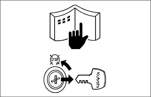
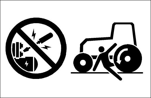
• Do not touch the rotating or hot parts while the engine is running.
• Never remove the radiator cap while the engine is running, or immediately after stopping. Otherwise, hot water will spout out from radiator. Only remove radiator cap when cool enough to touch with bare hands. Slowly loosen the cap to first stop to relieve pressure before removing completely.
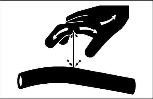
• Escaping fluid (fuel or hydraulic oil) under pressure can penetrate the skin causing serious injury. Relieve pressure before disconnecting hydraulic or fuel lines. Tighten all connections before applying pressure.
• Fuel is extremely flammable and explosive under certain conditions. Do not smoke or allow flames or sparks in your working area.
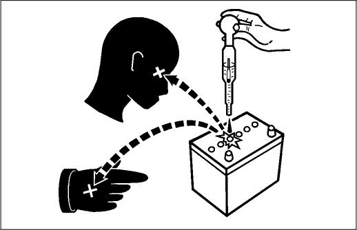
• To avoid sparks from an accidental short circuit, always disconnect the battery negative cable first and connect it last.
• Battery gas can explode. Keep sparks and open flame away from the top of battery, especially when charging the battery.
• Make sure that no fuel has been spilled on the engine.
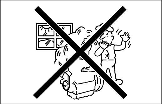

• If the engine must be running to do some work, make sure the area is well ventilated. Never run the engine in a closed area. The exhaust gas contains poisonous carbon monoxide.
• Sulfuric acid in battery electrolyte is poisonous. It is strong enough to bum skin, clothing and cause blindness if splashed into eyes. Keep electrolyte away from eyes, hands and clothing. If you spill electrolyte on yourself, flush with water, and get medical attention immediately.
• Do not pour fluids into the ground, down a drain, or into a stream, pond, or lake. Observe relevant environmental protection regulations when disposing of oil, fuel, coolant, electrolyte and other harmful waste.
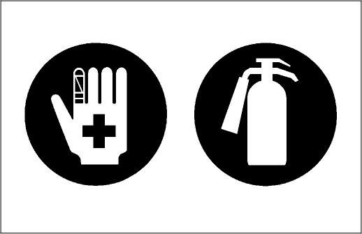
• Keep a first aid kit and fire extinguisher handy at all times.
• Keep emergency numbers for doctors, ambulance service, hospital and fire department near your telephone.
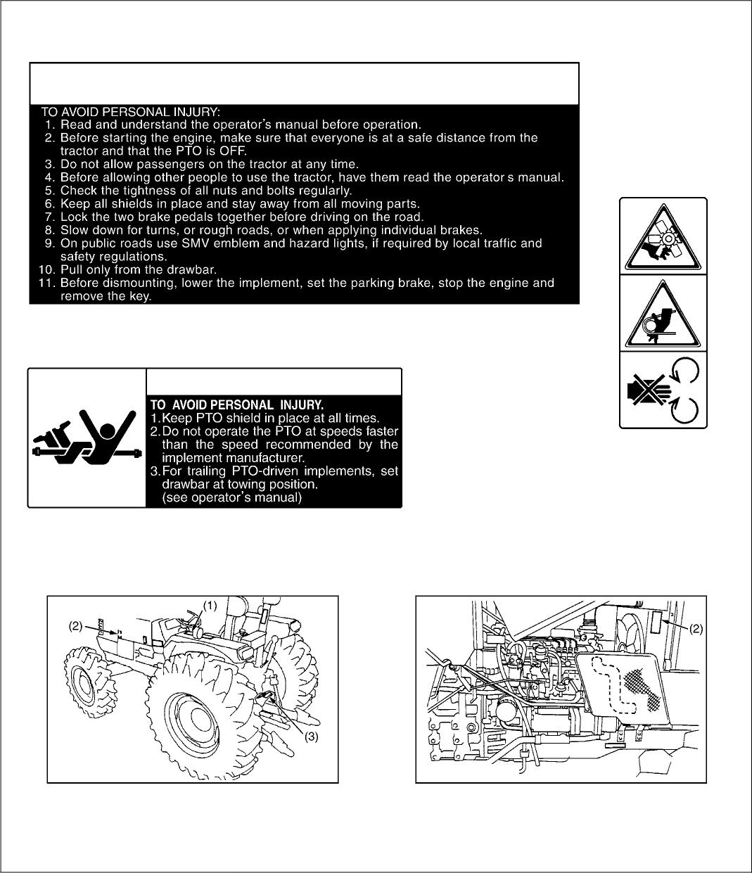
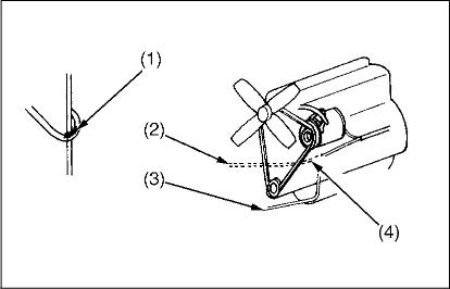
The following safety decals are installed on the machine. If a decal becomes damaged, illegible or is not on the machine, replace it. The decal part number is listed in the parts list.
(1) Part No.TA040-4965-2 & DANGER
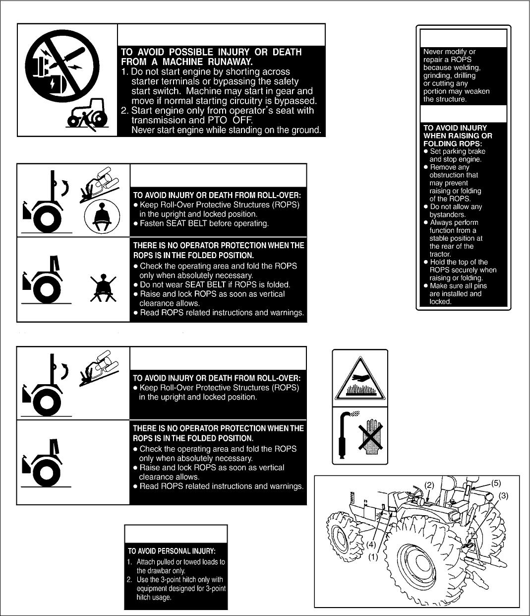
(5) Part No. 3A111-9544-1 & WARNING & CAUTION
(2) Part No.3A111-9848-2 (for North America andOceania) & WARNING
(2) Part No.3A1149848-1 (for Euro and Asia) & WARNING
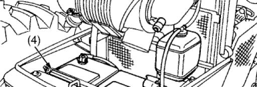
(4) Part No. 32310-4958-1 Do not touch hot surfacelikemuffler, etc.
(3) Part No.TA040•4935-1 & WARNING
(1) Part No. 35260-3491-3
(2) Part No. 32751-4958-1 Slay clear of engine fan and fanbelt.
(3) Part No.TA040•4959•3
(1) Part No. 35080-6528-2 & CAUTION

(2) Part No.TA040-4956-2


(3) Part No. 3A111-9856-3 & CAUTION
(4) Part No. 6C040-5559-1 (for Euro, Australia and Asia)
Cigatetes, lames o sparM could cause balt8ry to explode. Always shield 8ÿ0S d£id IdC8 from battery. Do not charge or use booster œbles or adjust post CorlrlOctiOriS Without pF0peF inStMCtiOrl arÏd trbinîrlg.
KEEP VENT CAPSTIGHT AND LEVEL
POISON cAUSES SEVERE BURNS
Contains sulfuric acid. Avoid contact with Ckin, 8yes or clOthing. In event of accident flush with water and call aphysician immediately.
KEEP OUT OF REACH OF CHILDREN


1. Keep danger, warning and caution labels clean and free from obstructing material.
2. Clean danger, warning and caution labels with soap and water, dry with a soft cloth.
3. Replace damaged or missing danger, warning and caution labels with new labels
4. If a component with danger, warning and caution labels as the replaced component.
5. Mount new danger, warning and caution labels by applying on a clean dry surface and pressing any bubbles to outside edge.
3TMACABCP003A
Model
Engine
Dimensions
Travelling system
M6800
Model V3300 E/ V3300 E2
Type Vertical, water-cooled, 4-cycle diesel engine
Number of cylinders 4
Total displacement 3318 cm’ (202.5 cu.in.)
Bore and stroke 98 x 110 mm(3.9 4.3 in.)
Net power 50.8 kW (6B HP)*
PTO power (factory observe) 46.3kW (62 HP)” / 2600 min 1 (rpm)
M6800S
Hydraulic system
Maximum torque 235 N m (24.0 kgf m, 173.3 ft-lbs) / 1300 to 1500 min"' (rpm)
Battery capacity 12 V, CCA : 1000 A
Fuel Diesel fuel No. 1 [below 10 °C (14 °F], Diesel fuel No. 2 D [above 10 °C (14 °F)]
Fuel tank capacity 65 L (17.2 U.S.gals., 14.3 Imp.gals.)
Engine oil capacfry 10.7 L (11.3 U.S.qts., 9.4 Imp.qts.)
Coolant capacity 8.5 L (9.0 U.S.qts., 7.5 Imp.qts.)
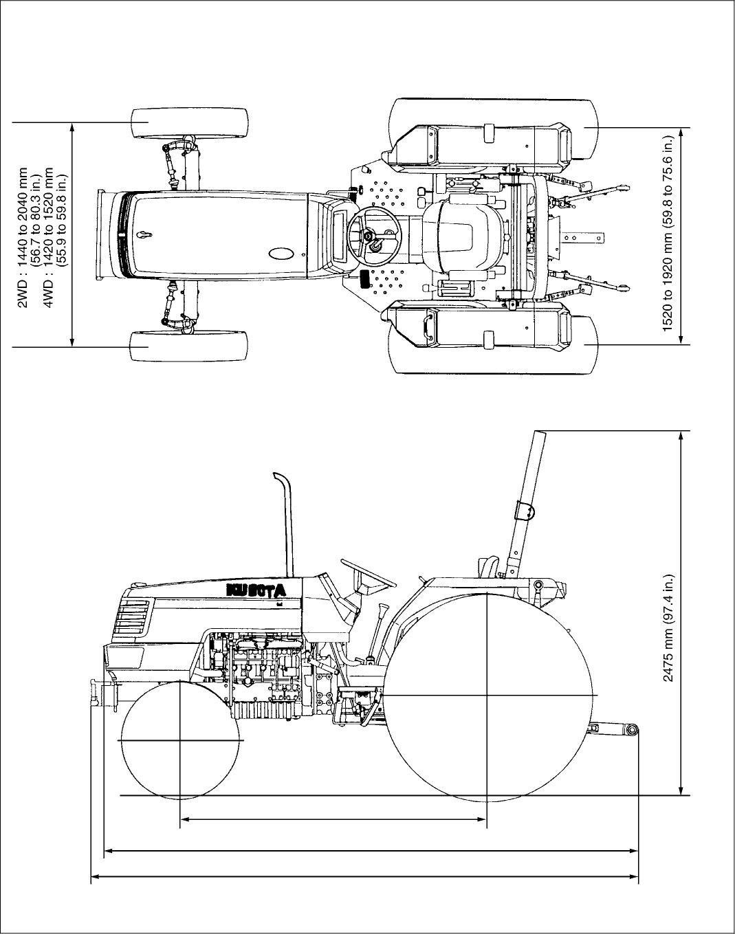
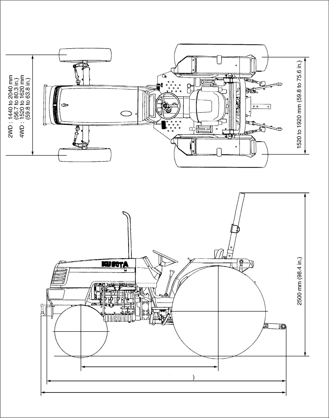
Overall height (with ROPS) 2450 mm (96.9 in.) Wheel
mm (B0.7 in.)
Minimum ground clearance 430 mm (16.9 in.) (COVER TANK) 430 mm (16.9 in.) (BRACKET DRAWBAR)
Clutch
StQCtring
Braking system
Dry, single plate
Hydrostatic power steering
Multiple wet disc mechanical
DiPerential Bevel gears with differential lock (Front, Rear)
Three point hitch
Max. lifting farce At lift points
SAE Category I & 0
2050 kg (4520 lbs) 24 in. behind lift points 1500 kg (3307 lbs)
Remote hydraulic control
One remote valve
System pressure 19.1 MPa (195 kgf/cm‘, 2775.4 psi)
Direction of turning
PTO Live PTO (Indipendent)
Standard PTO
Clockwise, viewed from tractor rear
Fixed PTO shaft type with 1 speed : 540 min"' (rpm) at 2295 min"' (rpm)
Fixed PTO shaft type with 2 speeds : 540 min"' (rpm) at 2307 min 1 (rpm) 1000 min 1 (rpm) at 2471 m] 1 (rpm)
Fixed PTO shaft type with 2 speeds : 540 min ' (rpm) at 2307 min 1 (rpm) 540E min 1 (rpm) at 1828 m 1 (rpm)
Note : ” Manufacture's estimate "At lower link and with links horizontal. The company reserves the right tochange the specifications without notice.
Model
Engine
Model
Type
Number of cylinders 4
Total
L (23.8 U.S.gals., 19.B Imp.gals.)
Engine ail capacity 10.7 L (11.3 U.S.qts., 9.4 Imp.qts.)
Coolant capacity 9.0 L (9.5 U.S.qts., 7.9 Imp.qts.) Dimensions
ground clearance
mm (16.9 in.) (BRACKET DRAWBAR)
(17.7 in.) (BRACKET DRAWBAR)
Clutch
Travelling system
Dry, single plate
Steenng Full hydrastatic power steering
Braking system
Differential
Hydraulic control system
u p capacity
Hydraulic system
Multiple wet disc mechanical
Bevel gears with differential lock (Front, Rear)
Position, draft and mix control
Individual flow type 41.3 L (43.6 U.S.qts., 36.3 Imp.qts.) / min.
combine flow type
L (67.9 U.S.qts., 56.6 Imp.qts.) / min.
Three paint hitch SAE CategoryII
Max. lifting forœ At lift points"
24 in. behind lift points
System pressure
Direction of turning
PTO Live PTO (Indipendent)
PTO / engine speed
Standard : 2500 kg(5560 lbs) with assist cylinder : 3400 kg (7497 lbs)
Standard : 2100 kg(4630 lbs) with assist cylinder : 2900 kg (6395 lbs)
Individual flaw type pump : 19.1 MPa (195 , 2775.4 psi) Combine flaw type pump : 19.6 MPa (200 2846.6 psi)

Clockwise, viewed from tractor rear
Fixed PTO shaft ape with 1 speed : 540 mm ' (rpm) at 2205 mm ' (rpm)
Fixed PTO shaft ape with 2 speeds : 540 m 1 (rpm) at 2035 min 1 ) 540E m 1 (rpm) at 1519 m 1t )
Interchangeable PTO shaft type : 540 min 1 (rpm) at 2035 m 1 (rpm) 1000 min"' (rpm) at 2389 min 1 (rpm)
Note : *Manufacture's estimate "At lower link and with links horizontal. The company reserves the right to change the specifications without notice.
M6800 ' M6800S
3TMACABFP001A

2050 mm (80.7 in.)
4WD (M6800) 3420 mm 134 in.) (M6800S) : 3525 mm (138.8 in.)
2WD (M6800) : 3530 mm (139.0 in.) (M6800S) : 3560 mm (140.2 in.)
2250 mm (88.6 in.)
4WD : 3800 mm (150.0 in.)
2WD : 3915 mm (154.1 in.) 3TMACABFP001B
M9000
C
2250 mm (88.6 in.)
4WD : 3800 mm (150.0 in.
2WD : 3915 mm (154.1 in.)

3TMACAB0P001 A
1. New Design Full-open Hood and Flat Top Fender
2. Hydrostatic Power Steering
3. Synchro-Shuttle
Lo-Reverse [M6800] Forward-Reverse [M6800S M8200 M9000]
4. Hydraulic Independent PTO
5. Foldable ROPS
6. New Transmission [M6800]
- Main Shift : Partially Synchronized
- Forward 8 / Reverse 4 Speeds
- Forward 12 / Reverse 4 Speeds (with Creep, if equipped) [M6800S M8200 M9000]
- Main Shift : Full Synchronized - Forward 8 / Reverse 8 Speeds
- Forward 12 / Reverse 12 Speeds (with Creep, if equipped)
7. Semi-Flat Deck and Rubber Mounted Deck
8. Hanging Pedal
9. New E-TVCS Diesel Engine Low Noise and Vibration High Torque Rise
10.Wet Disc Brake
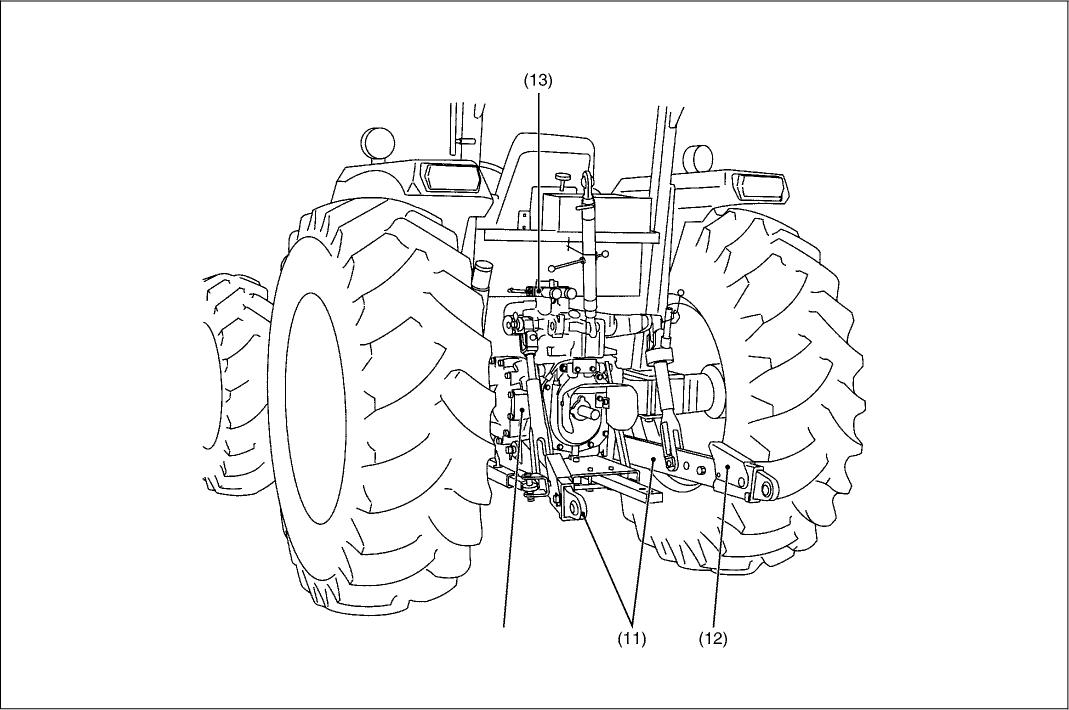
11.Three Point Hitch with Big Lift Power
12.Telescope Lower Link (M8200 M9000)
13.Remote Valve
Self-Cancelling with Detents (Standard)
Flow Control Valve (Option)
Floating Valve with Detent (Option)

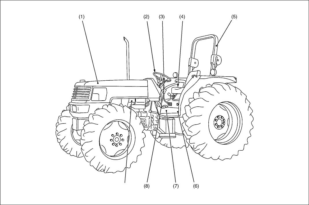
When contacting your local KUBOTA distributor, always specify engine serial number, tractor serial number and hourmeter reading. (1) Tractor Identification Plate (3) Engine Serial Number (2) Tractor Serial Number
3TMACAB0P003A
3TMACAB0P004A
3EEABAB1 P010A
The engine serial number is an identified number for the engine. It is marked after the engine model number. It indicates month and year of manufacture as follows.
• Year of manufacture
• Month of manufacture
Month Engine Serial Number 0001 9999 10000
January A0001 A9999 B0001
February C0001 C9999 D0001
March E0001 E9999 F0001
April G0001 G9999 H0001
May J0001 J9999 K0001
June L0001 L9999 M0001
July N0001 N9999 P0001
August Q0001 Q9999 R0001
September 50001 59999 T0001
October U0001 U9999 V0001
November W0001 W9999 X0001
December Y0001 Y9999 Z0001
e.g. V3300-YA0001
“Y” indicates 2000 and “A” indicates January. So, YA indicates that the engine was manufactured on January, 2000.
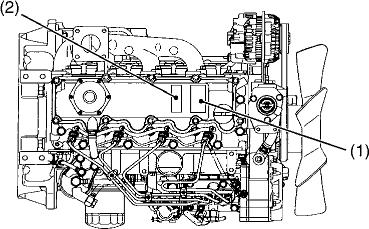
(1) Engine Model and Serial Number
3TMACAB0P053A
[ex.: Model Name V3300-E2]
The emission controls that have been put into effect in various countries to prevent air pollution will be stepped up. The time to enforce the regulations differs depending on the engine output classifications.
Kubota has been supplying the diesel engines conforming to the emission regulations in respective countries. Exhaust emissions regulations shift to the second stage. Kubota executed the improvement of the engine according to this regulation.
In order to discriminate the engines conforming to Tier 1 / Phase 1 requirements and those conforming to Tier 2 / Phase 2 requirements, we have adopted E2 as a new model name for the engines conforming Tier 2 / Phase 2 regulations with emission label (1) or (2).
In the after-sale services for V3300-E2, V3300-TE2 and V3300TIE2 series engines, only use the dedicated parts for E2 models and carry out the maintenance services accordingly.
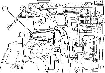
(1) Emission Label for EPA (2) Emission Label for EC
3EEABAB1 P011A
W1113734
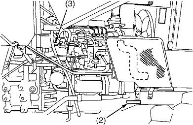
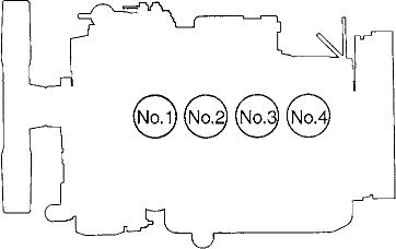
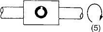
The cylinder numbers of V3300-E2, V3300-TE2 and V3300-TIE2 diesel engine are designated as shown in the figure.
The sequence of cylinder numbers is given as No.1, No.2, No.3 and No.4 starting from the gear case side.
W1011077


3TMABAB0P005A
• During disassembly, carefully arrange removed parts in a clean area to prevent confusion later. Screws, bolts and nuts should be installed in their original position to prevent reassembly errors.
• When special tools are required, use KUBOTA genuine special tools. Special tools which are not frequently used should be made according to the drawings provided.
• Before disassembling or servicing electrical wires, always disconnect the ground cable from the battery first.
• Remove oil and dirt from parts before measuring.
• Use only KUBOTA genuine parts for parts replacement to maintain machine performance and to assure safety.
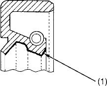
• Gaskets and O-rings must be replaced during reassembly. Apply grease to new O-rings or oil seals before assembling. See the figure left side.
• When reassembling external snap rings or internal snap rings, they must be positioned so that sharp edge faces against the direction from which a force is applied. See the figure left side.
• When inserting spring pins, their splits must face the direction from which a force is applied. See the figure left side.
• To prevent damage to the hydraulic system, use only specified fluid or equivalent.
(1) Grease
(2) Force
(3) Sharp Edge
(4) Axial Force
(S) Rotating Movement
(A) External Snap Ring
(B) Internal Snap Ring
W1010904
3TMABAB0P006A
To ensure safety and prevent damage to the machine and surrounding equipment, heed the following precautions in handling electrical parts and wiring.
■ IMPORTANT
• Check electrical wiring for damage and loosened connection every year. To this end, educate the customer to do his or her own check and at the same time recommend the dealer to perform periodic check for a fee.
• Do not attempt to modify or remodel any electrical parts and wiring.
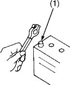
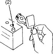
• When removing the battery cables, disconnect the negative cable first. When installing the battery cables, connect the positive cable first.
(1) Negative Terminal (2) Positive Terminal
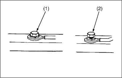
• Securely tighten wiring terminals.
(1) Correct (2) Incorrect
W1011114 (Securely Tighten) (Loosening Leads to Fault Contact)
W1011216
3TMABAB0P007A
3TMABAB0 P008A
3GFABAB0P003A
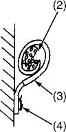
• Do not let wiring contact dangerous part.
(1) Wiring (Correct) (3) Dangerous Part (2) Wiring (Incorrect) (4) Dangerous Part
W1011313
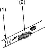
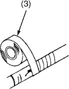
• Repair or change torn or aged wiring immediately.
(1) Aged (3) Insulating Vinyl Tape (2) Torn
W1012292
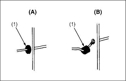
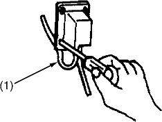
• Securely insert grommet. (1) Grommet (A) Correct (B) Incorrect
W1011388
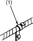
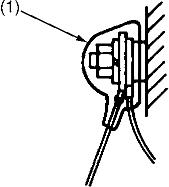
• Securely clamp, being careful not to damage wiring. (1) Clamp (3) Clamp
•Wind Clamp Spirally (4) Welding Dent (2) Wire Harness
W1011458
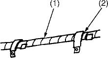
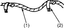
• Clamp wiring so that there is no twist, unnecessary sag, or excessive tension, except for movable part, where sag be required.
(1) Wiring (2) Clamp (A) Correct (B) Incorrect
W1011587
• In installing a part, take care not to get wiring caught by it. (1) Wiring (A) Incorrect
W1011670
• After installing wiring, check protection of terminals and clamped condition of wiring, only connect battery. (1) Cover
• Securely Install Cover
W1011735
3TMABAB0P006B

• Take care not to confuse positive and negative terminals.
• When removing battery cord, disconnect negative wire first. When installing battery cord, check for polarity and connect positive wire first.
• Do not install any battery with capacity other than is specified (Ah).
• After connecting cord to battery terminals, apply grease to them and securely install terminal covers on them.
• Do not allow dirt and dust to collect on battery.
• Take care not to let battery liquid spill on your skin and clothes. If contaminated, wash it off with water immediately.
• Before recharging the battery, remove it from the machine.
• Before recharging, remove cell caps.
• Do recharging in a well-ventilated place where there is no open flame nearby, as hydrogen gas and oxygen are formed.
W1011816
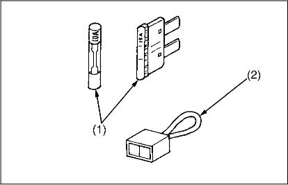
• Use fuses with specified capacity. Neither too large or small capacity fuse is acceptable.
• Never use steel or copper wire in place of fuse.
• Do not install working light, radio set, etc. on machine which isnot provided with reserve power supply.
• Do not install accessories if fuse capacity of reserve power supply is exceeded.
(1) Fuse (2) Slow Blow Fuse
W1012092
3TMABAB0P014A
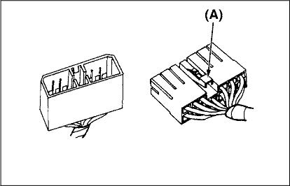
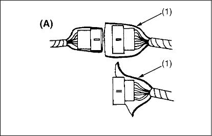
• For connector with lock, push lock to separate. (A) Push
W1012211
3TMABAB0P015A
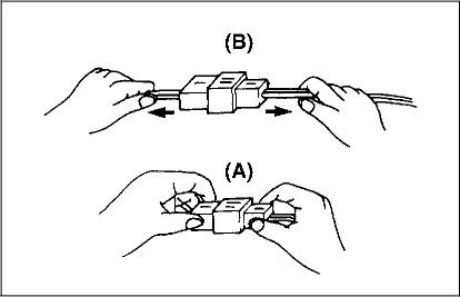
• In separating connectors, do not pull wire harnesses.
• Hold connector bodies to separate. (A) Correct (B) Incorrect
W1012272
3TMABAB0P016A

3TMABAB0P017A


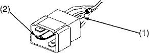
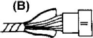
• Use sandpaper to remove rust from terminals.
• Repair deformed terminal. Make certain there is no terminal being exposed or displaced.
(1) Exposed Terminal (2) Deformed Terminal (3) Sandpaper (4) Rust
W1012346

• Make certain that there is no female connector being too open. (A) Correct (B) Incorrect
W1012430
3TMABAB0P018A
• Make certain plastic cover is large enough to whole (1) Cover (A) Correct (B) Incorrect
W1012519
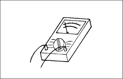
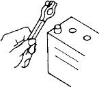
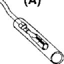
• Use tester correctly following manual provided with tester.
• Check for polarity and range.
W10126B4
3TMABAB0 P020A
Place
1 Fuel tank
2 Coolant 8.5 L 9.0 U.S.qts. 7.5 Imp.qts.
3 Engine crankcase
Lubricants, fuel and coolant
No. 2-D diesel fuel
No. 1-D diesel fuel if temperature is below 10 °C (14 °F)
Fresh clean water with anti-freeze
API Service Classification
CD, CE or CF
Below 0 °C (32 °F): SAE10W, 10W-30 or 10W-40
0 to 25 °C (32 to 77 °F): SAE20, 10W-30 or 10W-40
Above 25 °C (77 °F): SAE30, 10W-30 or 10W-40
4
5
6
■ NOTE
• Engine Oil : Oil used in the engine should have an American Petroleum Institute (API) service classification and Proper SAE Engine Oil according to the ambient temperature as shown above. Do not mix different brands together.
• With the emission control now in effect, the CF-4 and CG-4 lubricating oils have been developed for use of a low-sulfur fuel on-road vehicle engines. When an off-road vehicle engine runs on a high-sulfur fuel, it is advisable to employ the CF, CD or CE lubricating oil with a high total base number. If the CF-4 or CG4 lubricating oil is used with a high-sulfur fuel, change the lubricating oil at shorter intervals.
• Lubricating oil recommended when a low-sulfur or high-sulfur fuel is employed.
Fuel
Lubricating oil class
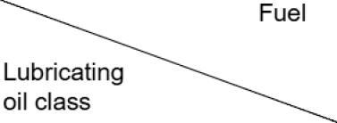
U : Recommendable X : Not reoommendable
• Transmission Oil : The oil used to lubricate the transmission is also used as hydraulic fluid. To insure proper operation of the hydraulic system and complete lubrication of the transmission, it is important that a multi-grade transmission fluid be used in this system. We recommend the use of KUBOTA SUPER UDT fluid for optimum protection and performance. Do not mix different brands together.
• Indicated capacity of water and oil are manufacture's estimate.
Screws, bolts and nuts whose tightening torques are not specified in this Workshop Manual should be tightened according to the table below.
Indicauon ontop of
Matenal of opponent


■
• The jobs indicated by A must be done after the first 50 hours of operation.
• ” : Air cleaner should be cleaned more often in dusty conditions than in normal conditions.
• : Every year or every 6 times of cleaning.
• ” : Replace only if necessary.
• The items listed above (@ marked) are registered as emission related critical parts by KUBOTA in the U.S.EPA nonroad emission regulation. As the engine owner, you are responsible for the performance of the required maintenance on the engine according to the above insbuction.
Please see the Warranty Statement in detail.
• Be sure to check and service the tractor on a flat place with engine shut off, the parking brake on and chock the wheels.
To prevent trouble from occurring, it is important to know the condition of the tractor. Check the following items before starting.
Checking
• Check areas where previous trouble was experienced.
• Walk around the tractor.
1. Check the tire pressure, and check for wear and damage.
2. Check for oil and water leaks.
3. Check the engine oil level.
4. Check the transmission fluid level.
5. Check the coolant level.
6. Check the condition of ROPS attaching hardware.
7. Check and clean the radiator screen and grill.
8. Check the bolts and nuts of the tires are tight.
9. Check the number plate or SMV emblem for damage and cleaner replace as necessary if equipped.
10.Care of danger, warning and caution labels.
11.Clean around the exhaust manifold and the muffler of the engine.
• While sitting in the operator's seat.
1. Check the throttle pedal, brake pedals and clutch pedal.
2. Check the parking brake.
3. Check the steering wheel.
• Turning the key switch.
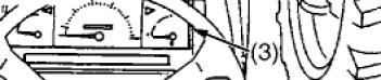
1. Check the performance of the Easy Checker lights.
2. Check head lights, tail lights and hazard light.
Clean if necessary.
3. Check the performance of the meters and gauges.
• Starting the engine.
1. Check to see that the lights on the Easy Checker go off.
2. Check the color of the exhaust.
3. Check the brakes for proper operation.