5103 5203 Repair Manual John Deere Manual TM900019
John Deere Agriculture
5103, 5203, 5303, 5403, 5045, 5055, 5065 And 5075 USA, Mexico and Australia Tractors; 5103, 5203, 5303 And 5403 Australia Tractors; 5303 And 5403 Latin America Tractors; 5204 And 5303 Mexico Tractors
TECHNICAL MANUAL
Models 5303, 5103, 5203, 5204, 5403
TM900019, September 2013
Table of contents
FOREWORD
Section 10 - GENERAL INFORMATION
Group 05 - Safety
Group 10 - General Specifications
Group 15 - Fuel and Lubricants
Group 20 - Serial Number Locations
Group 25 - Features and Accessories
Section 20 - ENGINE REPAIR
Group 05 - Engine
Group 10 - Cylinder Head and Valves
Group 15 - Cyl. Block, Liners, Pistons & Rods
Group 20 - Crankshaft, Main Bearings and Flywheel
Group 25 - Camshaft and Timing Gear Train
Group 30 - Lubrication System
Group 35 - Cooling System
Section 30 - FUEL AND AIR REPAIR
Group 05 - Fuel System
Group 10 - Air Intake and Exhaust System
Group 15 - Speed Control Linkage
Section 40 - ELECTRICAL REPAIR
Group 05 - Battery, Starter and Alternator
Group 10 - Electrical System Components
Group 15 - Wiring Harness
Section 50 - POWER TRAIN REPAIR
Group 05 - Clutch Housing
Group 10 - Clutch Assembly
Group 15 - ′S′ Transmission
Group 20 - ′AA′ Transmission
Group 21 - Rear PTO (′S′ Transmission)
Group 25 - Rear PTO (′AA′ Transmission)
Group 26 - Differential
Group 30 - Final Drives
Group 35 - Mechanical Front Wheel Drive
Section 60 - STEERING AND BRAKE REPAIR
Group 05 - Steering Repair
Group 10 - Brake Repair (′S′ Transmission)
Group 15 - Brake Repair (′AA′ Transmission)
Section 70 - HYDRAULIC REPAIR
Group 05 - Hydraulic Pump and Filter
Group 10 - MITA Rockshaft
Group 15 - JD Rockshaft
Group 20 - MITA Selective Control Valve (SCV)
Group 25 - EATON Selective Control Valve (SCV)
Group 30 - Mid Mount Selective Control Valve (SCV)
Section 80 - MISCELLANEOUS REPAIR
Group 05 - Front Axle - 2WD
Group 10 - Wheels
Group 15 - 3-Point Hitch
Group 25 - Hood
Section 90 - OPERATOR STATION REPAIR
Group 05 - Seat and Support
Group 06 - Center Console
Group 10 - Roll-GardRoll-Gard is a trademark of Deere & Company
Group 15 - Operator Platform
Group 20 - Fenders
Group 25 - Canopy (If Equipped)
Section 210 - OPERATIONAL CHECKOUT PROCEDURES
Group 10 - Operational Checkout Procedures
Section 220 - ENGINE OPERATION, TESTS AND ADJUSTMENTS
Group 05 - Component Location
Group 10 - Theory of Operation
Group 15 - Diagnosis, Tests and Adjustments
Section 230 - FUEL/AIR OPERATION, TEST AND ADJUSTMENTS
Group 05 - Component Location
Group 10 - Theory of Operation
Group 15 - Diagnosis, Tests and Adjustments
Section 240 - ELECTRICAL SYSTEM OPERATION, TESTS & ADJUST
Group 05 - Component Location
Group 10 - Theory of Operation—Latin America, Mexico, USA and Australia (5103, 5203, 5303, 5403) Tractors
Group 15 - Theory of Operation—USA and Australia Tractors
Group 20 - Diagnosis, Test and Adjust—Latin America, Mexico (5303), USA and Australia (5103, 5203, 5303, 5403) Tractors
Group 25 - Diagnosis, Test and Adjust—USA and Australia Tractors
Group 30 - Diagnosis, Test and Adjust (Mexico 5204 Tractors)
Group 35 - Wiring Schematics—Latin America, Mexico (5303), USA and Australia (5103, 5203, 5303, 5403) Tractors
Group 40 - Wiring Schematics—For USA and Australia Tractors
Group 45 - Wiring Schematics (Mexico 5204 Tractors)
Group 50 - Component Information—Connectors(For USA and Australia Tractors)
Section 250 - POWER TRAIN OPERATION, TESTS AND ADJUSTMENTS
Group 05 - Component Location—Transmission
Group 10 - Theory of Operation—Transmission
Group 15 - Diagnosis, Tests, and Adjustments-Transmission
Section 260 - STEERING AND BRAKE OPERATION, TEST & ADJUSTMENTS
Group 05 - Component Location
Group 10 - Theory of Operation
Group 15 - Diagnosis, Tests and Adjustments
Section 270 - HYDRAULIC SYSTEM OPERATION, TEST AND ADJUSTMENTS
Group 05 - Component Location
Group 10 - Theory of Operation
Group 15 - Diagnosis
Group 20 - Hydraulic Tests - Without SCV
Group 25 - Hydraulic Tests—With SCV
Group 18 - Hydraulic Tests—With Mid Mount Control Valve
Group 30 - Hydraulic Tests - All
Group 40 - Adjustments
Group 45 - Hydraulic Schematics
Foreword
This manual is written for an experienced technician. Essential tools required in performing certain service work are identified in this manual and are recommended for use.
Live with safety: Read the safety messages in the introduction of this manual and the cautions presented throughout the text of the manual.
CAUTION:
This is the safety-alert symbol. When you see this symbol on the machine or in this manual, be alert to the potential for personal injury.
Technical manuals are divided in two parts: repair and operation and tests. Repair sections tell how to repair the components. Operation and tests sections help you identify the majority of routine failures quickly.
Information is organized in groups for the various components requiring service instruction. At the beginning of each group are summary listings of all applicable essential tools, service equipment and tools, other materials needed to do the job, service parts kits, specifications, wear tolerances, and torque values.
Technical Manuals are concise guides for specific machines. They are on-the-job guides containing only the vital information needed for diagnosis, analysis, testing, and repair.
Fundamental service information is available from other sources covering basic theory of operation, fundamentals of troubleshooting, general maintenance, and basic type of failures and their causes.
Section 10 - GENERAL INFORMATION
Group 05 - Safety
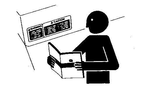
Recognize Safety Information
Safety-alert symbol
This is a safety-alert symbol. When you see this symbol on your machine or in this manual, be alert to the potential for personal injury.
Follow recommended precautions and safe operating practices.
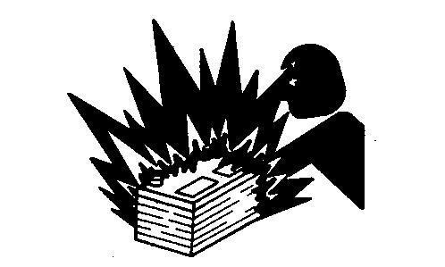
Understand Signal Words
Signal Words
A signal word—DANGER, WARNING, or CAUTION—is used with the safety-alert symbol. DANGER identifies the most serious hazards.
DANGER or WARNING safety signs are located near specific hazards. General precautions are listed on CAUTION safety signs. CAUTION also calls attention to safety messages in this manual.
Follow Safety Instructions
Safety Messages
Carefully read all safety messages in this manual and on your machine safety signs. Keep safety signs in good condition. Replace missing or damaged safety signs. Be sure new equipment components and repair parts include the current safety signs. Replacement safety signs are available from your John Deere dealer.
Learn how to operate the machine and how to use controls properly. Do not let anyone operate without instruction.
Keep your machine in proper working condition. Unauthorized modifications to the machine may impair the function and/or safety and affect machine life.
If you do not understand any part of this manual and need assistance, contact your John Deere dealer.
Handle Fluids Safely—Avoid Fires
Avoid Fires
When you work around fuel, do not smoke or work near heaters or other fire hazards.
Store flammable fluids away from fire hazards. Do not incinerate or puncture pressurized containers.
Make sure machine is clean of trash, grease, and debris.
Do not store oily rags; they can ignite and burn spontaneously.
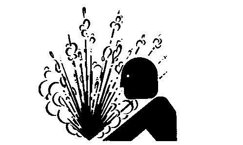
Prevent Battery Explosions
Battery Explosions
Keep sparks, lighted matches, and open flame away from the top of battery. Battery gas can explode.
Never check battery charge by placing a metal object across the posts. Use a volt-meter or hydrometer.
Do not charge a frozen battery; it may explode. Warm battery to 16°C (60°F).
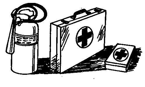
Prepare for Emergencies
First Aid Kit
Be prepared if a fire starts.
Keep a first aid kit and fire extinguisher handy.
Keep emergency numbers for doctors, ambulance service, hospital, and fire department near your telephone.
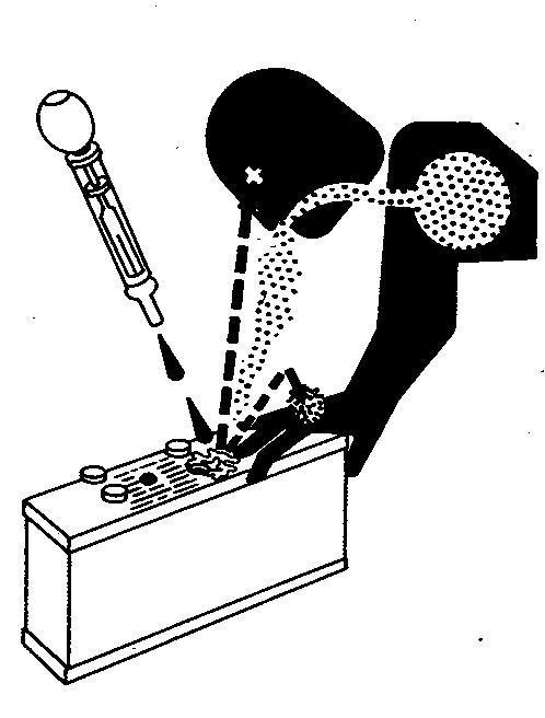
Prevent Acid Burns
Acid Burns
Sulfuric acid in battery electrolyte is poisonous. It is strong enough to burn skin, eat holes in clothing, and cause blindness if splashed into eyes.
Avoid the hazard by:
Filling batteries in a well-ventilated area.1.
Wearing eye protection and rubber gloves.2.
Avoiding breathing fumes when electrolyte is added.3.
Avoiding spilling or dripping electrolyte.4.
Use proper jump start procedure.5.
If you spill acid on yourself:
Flush your skin with water.1.
Apply baking soda or lime to help neutralize the acid.2.
Flush your eyes with water for 15—30 minutes. Get medical attention immediately.3.
If acid is swallowed:
Do not induce vomiting.1.
Drink large amounts of water or milk, but do not exceed 2 L (2 quarts).2.
Get medical attention immediately.3.
Service Cooling System Safely
Cooling System
Explosive release of fluids from pressurized cooling system can cause serious burns.
Shut off engine. Only remove filler cap when cool enough to touch with bare hands. Slowly loosen cap to first stop to relieve pressure before removing completely.
Avoid High-Pressure Fluids
High-Pressure Fluids
Escaping fluid under pressure can penetrate the skin causing serious injury. Avoid the hazard by relieving pressure before disconnecting hydraulic or other lines. Tighten all connections before applying pressure.
Search for leaks with a piece of cardboard. Protect hands and body from high pressure fluids.
If an accident occurs, see a doctor immediately. Any fluid injected into the skin must be surgically removed within a few hours or gangrene may result. Doctors unfamiliar with this type of injury should reference a knowledgeable medical source. Such information is available from Deere & Company Medical Department in Moline, Illinois, U.S.A.
Park Machine Safely
Remove the Key
Before working on the machine:
Lower all equipment to the ground. Stop the engine and remove the key. Disconnect the battery ground strap.
Hang a "DO NOT OPERATE" tag in operator station.
Support Machine Properly
Support Properly
Always lower the attachment or implement to the ground before you work on the machine. If the work requires that the machine or attachment be lifted, provide secure support for them. If left in a raised position, hydraulically supported devices can settle or leak down.
Do not support the machine on cinder blocks, hollow tiles, or props that may crumble under continuous load. Do not work under a machine that is supported solely by a jack. Follow recommended procedures in this manual.
When implements or attachments are used with a machine, always follow safety precautions listed in the implement or attachment operator′s manual.
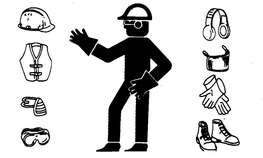
Wear Protective Clothing
Protective Clothing
Wear close fitting clothing and safety equipment appropriate to the job.
Prolonged exposure to loud noise can cause impairment or loss of hearing.
Wear a suitable hearing protective device such as earmuffs or earplugs to protect against objectionable or uncomfortable loud noises.
Operating equipment safely requires the full attention of the operator. Do not wear radio or music headphones while operating machine.
Section
Group 30 - Hydraulic Tests - All
MITA Rockshaft Leakage Test
. Slide LV4567
LEGEND:
ARate-of-Drop Valve
BRockshaft Draft Lever
REASON:
To determine if leakage exists in rockshaft cylinder, or valve.
PROCEDURE:
Section
[1] - Attach minimum weight of 45 kg (100 lb) to draft links.
[2] - Close rate-of-drop valve (A).
[3] - Move rockshaft position lever (B) all the way forward.
[4] - Rockshaft should drop slightly, then hold.
RESULTS:
If rockshaft drops, there is leakage past rockshaft piston, seals, or surge (safety) relief valve. Remove rockshaft housing and inspect. Replace parts as necessary.
Section
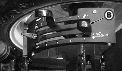
JD Rockshaft Leakage Test
Rockshaft Leakage Test
LEGEND:
ARockshaft Control Valve
BRate-of-Drop Knob
REASON:
To determine if leakage exists in rockshaft cylinder, housing, or valve.
PROCEDURE:
[1] - Attach minimum weight of 45kg (100 lb) to draft links.
[2] - Place blocks under weight to keep it raised.
[3] - Lower rockshaft so weight settles fully on blocks or stands.
[4] - Move rockshaft position lever all the way forward. Open rate-of-drop valve (B).
Section
[5] - Remove right rear wheel, if necessary.
[6] - Using jack or other lifting device, lift weight off blocks and allow implement to lower.
[7] - Rockshaft should drop slightly, then hold.
[8] - Install wheel, if removed.
RESULTS:
If rockshaft drops, there is leakage past rockshaft piston, seals, or surge (safety) relief valve. Remove rockshaft housing and inspect. Replace parts as necessary.
Section 270 - HYDRAULIC SYSTEM OPERATION, TEST AND ADJUSTMENTS
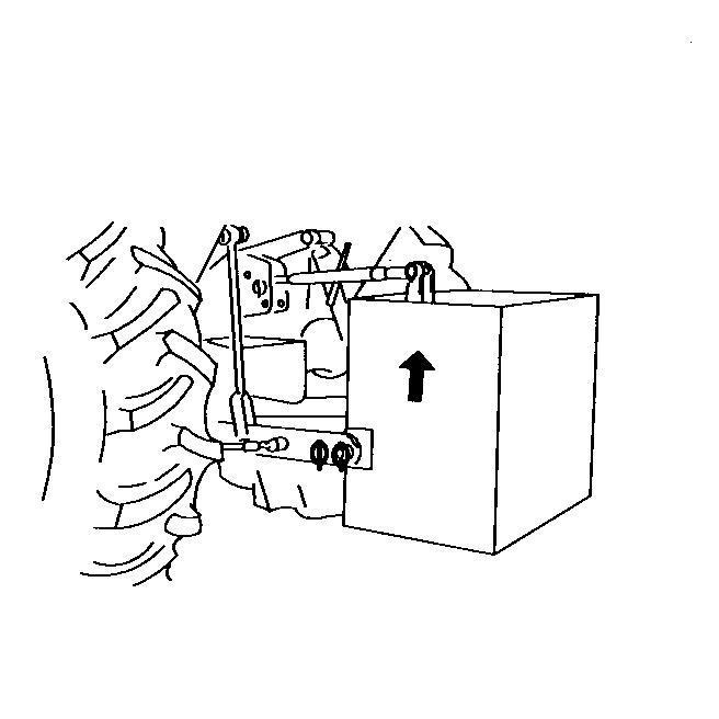
Rockshaft Lift Cycle Test
Group 30: Hydraulic Tests - All
Rockshaft Lift Cycle Test
REASON:
To determine if hydraulic flow can provide enough force to lift the 3-point hitch arms as designed.
PROCEDURE:
[1] - Attach approximately 227 kg (500 lb) rear weight or implement.
Section
[2]→NOTE: Ballast Box could be used.
Open rate-of-drop valve completely.
[3] - Lower 3-point hitch completely.
[4] - Run engine at fast idle.
[5] - Observe the time it takes to completely raise the 3-point hitch arms after you pull the position lever all the way back.
SPECIFICATIONS:
Full lower to full raise in 2.5 to 3 seconds.
→NOTE:
The speed at which the hitch arms rise during the last few inches of travel at the highest position is slower than the rate of movement from the bottom. The difference in raise rates is normal due to the action of the flow regulator valve within the rockshaft control valve.
RESULTS:
If the raise time is excessive, leakage exists.
Perform the rockshaft leakage test, pump flow test and main relief valve test. If tractor passes these tests, the problem is the control valve, or a leaking seal or O-ring.
Group 40 - Adjustments
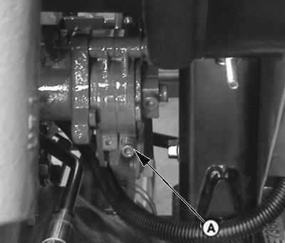
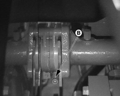
Rockshaft Sensing Lever Friction Adjustment - MITA Rockshaft
Section
REASON:
To keep the rockshaft position and draft-sensing levers in their set positions.
PROCEDURE:
Turn socket head screws (A) clockwise to increase friction, counterclockwise to1. decrease friction.
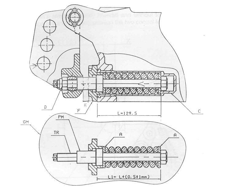
Control of Assembly of Reaction Spring- MITA Rockshaft
Reaction Spring
Reaction Spring
LEGEND: AWasher
CCover
PMSpring-Loader TRRod GMGroup
Before assembly, control that the pre-assembled components satisfy the measurement L1.This permits a pre-loading of reaction spring of 0.5-1mm.
If this measurement is not correct then the washer “A” should be substituted with one which has an adequate width.
The spring- loader “PM” must be assembled on the rod “TR” with loctite thread locking glue nr.243 so as to not pre-load the reaction spring.
Assemble the group “GM” on the cover “C”, which is inserted in the body of the rockshaft, and tighten with two hexagonal head screws M12 which block the flange “F” to the body.
By moving the rod “TR”, an axial play. this play must be eliminated for the correct assembly of the group as follows:
Keep the rod “TR” fixed and rotate gradually inthe clockwise direction the spring-loader until the axial play is eliminated.
Complete the assembly of the top link bracket taking care not to rotate the rod “TR” during the tightening of the self-locking nut “D”.
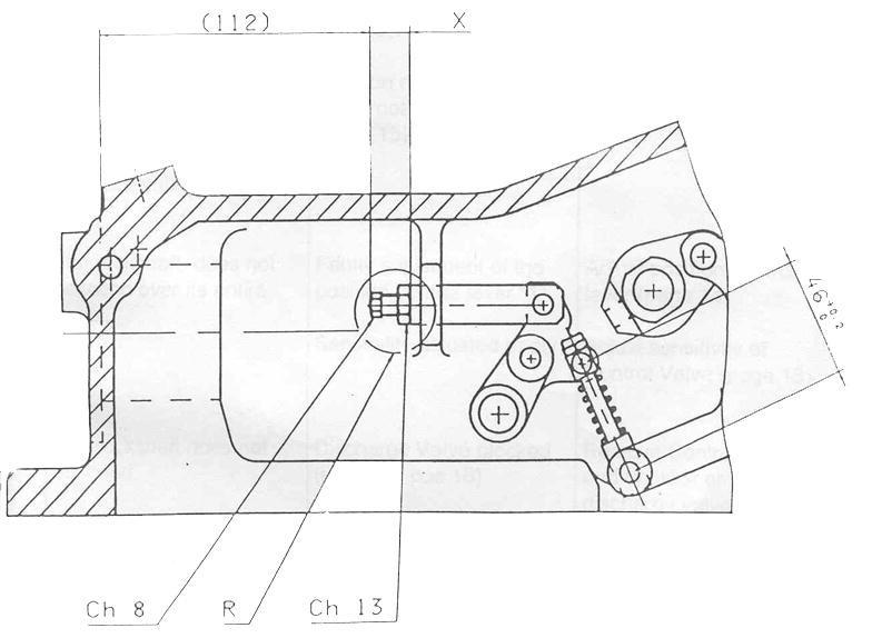
Measurement Control of Push rod- MITA Rockshaft
Reaction Spring
If the rockshaft is disassembled and if the regulator “R” must be changed it is advisable to control the measurement “X” (15 +/- 0.1mm) in order to re-assemble the push rod in the same position.
Ensure also that the measurement between the two pins diameter 8 of the push rod is 460 +/- 0.2mm.
The control of the measurement of the push rod with respect to the control valve face is carried out after making all the adjustments (sensitivity of control valve - position control lever - draft control lever)
With the rockshaft arms completely lowered and without loads or implements on the three point linkage (Park Position ) ; position the two control levers against the backstop.
In this position, pushing the internal push rod, verify with the appropriate guage that the distance of 112 is correct.
→NOTE:
If the measurement “X” is changed it is obligatory to re-adjust the position control lever and the draft control lever.
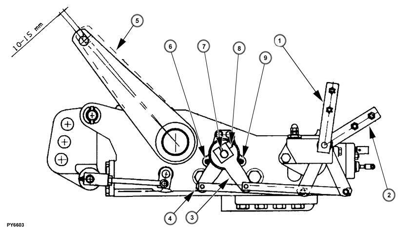
Adjustment of Position Control Lever- MITA Rockshaft
Position Control Lever
The adjustment is carried out in order to establish the maximum raised position of the rockshaft’s lifting arms. Completely lower the arms and apply a light weight. Loosen the fastening screw “6” so as to free the position control lever “1” from the shaft “5”. Lift completely the position lever “1” so that the lever “1R” goes against the backstop “F”. The draft lever “2” must be all down so that the lever “2R” is against the backstop “E”. Maintaining fixed the levers “1” and “2” and with a 13mm open end wrench rotate slowly in an anticlockwise direction the position control shaft “5” so as to raise the arms to their maximum raised position which is determined by the internal hydraulic limit stop. Since during the functioning of the position control the hydraulic limit stop must not to be
triggered it is necessary to have a safety margin of 10 mm. In order to do this, rotate slowly in a clockwise direction the shaft “5” until the arms are lowered by required safety margin. At this point keep the shaft “5” fixed and with lever “1R” against the backstop “F” keep the lever fixed with the shaft by tightening fully the fastening screw “6”. To control, raise and lower the arms by moving the position control lever “1” and control that the arms always reach the same position at their highest position. Then by raising also the draft lever “2” and lifting the arms the hydraulic limit stop is acting and it is possible to check the additional stroke upwards of the arms that should be kept in 10-15 mm.
Adjustment Of Draft Control Lever- MITA Rockshaft
Draft Control Lever
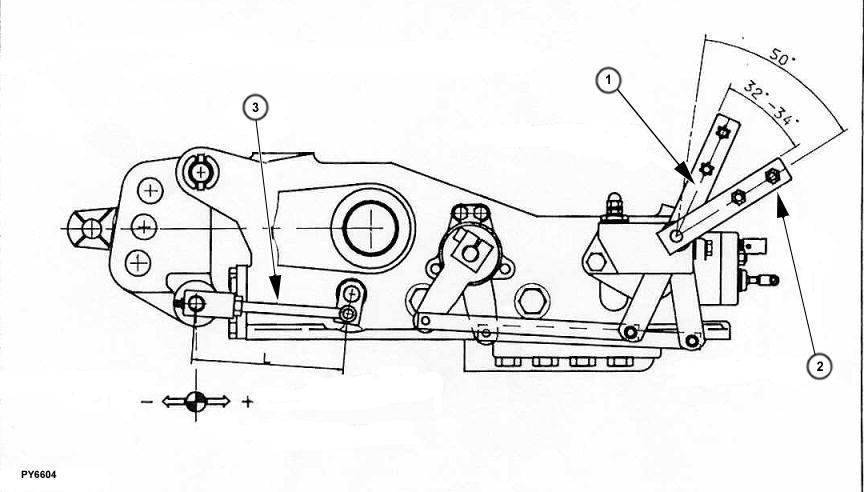
The adjustment of draft control lever is necessary in order to synchronise the movement of the lever itself and the stroke - positive or negative - of the top link bracket spring, so that it is possible to use all the working area of the spring. The adjustment has to be done with the top link bracket in Park position position with no load applied on the top link bracket. Put all levers “1” and “2” down. With the engine speed at the maximum lift slowly the draft lever “2”.
With the position control set so that arms do not interfere with the draft feedback rod “T”, set the draft lever to the Park position position as indicated on the lever quadrant, that corresponds to and angle of 32 to 34 degrees on the rockshaft controls “1” and “2”. Adjust teh yoke on the draft feedback rod “T” one revolution at a time until the precise location where the arms raised is found. Tighten the yoke on the draft feedback rod “T” and set the locking nut.
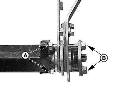
Friction Adjustment
LEGEND:
AJam Nut
BCap Screw
REASON:
To keep the rockshaft position and draft-sensing levers in their set positions.
PROCEDURE:
→NOTE:
SCV levers, right-hand fender and console removed for clarity.
[1] - Loosen jam nuts (A).
[2] - Turn adjusting cap screws (B) clockwise to increase friction, counterclockwise to decrease friction. Turn cap screws equal number of times.
[3] - Retighten jam nuts (A) when adjustment is complete.
To ensure that the lift arms have the proper range of motion.
PROCEDURE:
[1] - Remove left-side fender.
[2] - Remove fuel tank.
[3] - Remove all weight from center link.
[4] - Loosen jam nut (A).
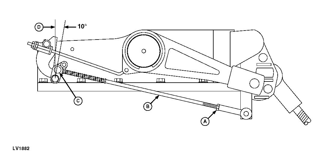
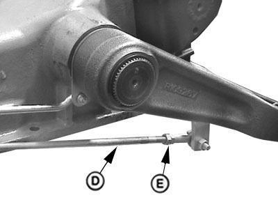
Section
[5] - Turn draft-sensing rod (B) so that pin (C) is approximately 10° clockwise from vertical line (D).
[6] - Tighten jam nut (A).
[7]IMPORTANT:
Loosen both nuts (A) to end of thread travel on rod to prevent damage to linkage. LEGEND:
Loosen both nuts (A) to end of thread travel on rod.
[8] - Manually raise rockshaft arms up until the upper limit is reached.
Section
[9]→NOTE:
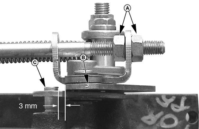
After clearance specification of 3 mm has been made, this adjustment will not be done again.
Turn adjustment nuts (A) so there is 3 mm clearance between arm (B) and pin (C). Lengthen or shorten rod to specification as shown in photo.
[10] - Isolated open operator platform and cab tractors: Install fuel tank.
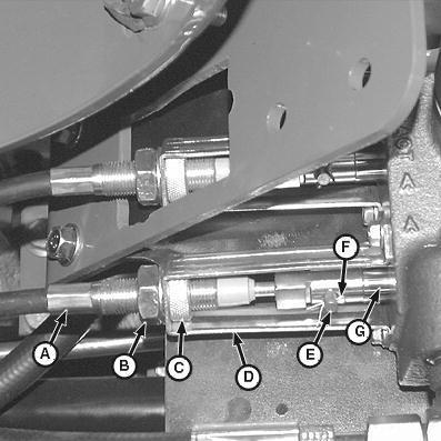
[11] -
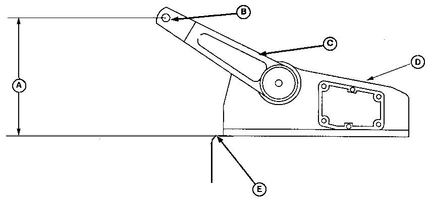
LEGEND:
AVertical Distance
BLift Arm Pin
CLift Arm
DRockshaft Housing
EDifferential Housing Top Face
Open rate-of-drop valve by turning knob fully counterclockwise.
[12] - Attach minimum weight of 20 to 35 kg (44 to 65 lb) to each draft link.
[13] - Push the position control lever and draft control levers fully forward.
Section
[14] - Start and run engine at 1500 rpm.
[15] - Move the outer lever (position control lever) fully rearward and then fully forward five times to purge air from the rockshaft piston and oil lines.
[16] - Move position control lever fully rearward and allow lift arms (C) to rise to top. Shut off engine.
[17] - Measure vertical distance (A) from top face of differential housing (E) to center of lift arm pin (B). If measurement is within specifications, no adjustment is necessary. Continue with procedure if distance is more or less than specification.
[18] - Install left-side fender.
ItemMeasurementSpecification
Vertical (A)Distance315 ± 4 mm (12.401 ± 0.157 in.)
Vertical (A)—For 5045E, 5055E 5065E and 5075E TractorsDistance315±2 mm (12.52 ±0.08 in.)
Vertical (A)—For 5045D and 5055D TractorsDistance385±4 mm (15±0.16 in.)
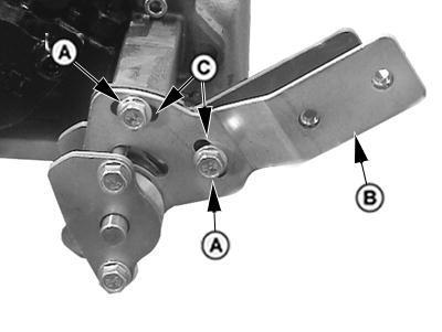
[19]. LEGEND:
AScrew (2 used)
BOuter Lever
CAdjustment Slot
Remove right-side fender.
[20] - If distance measured earlier is greater than the specification 319 mm (12.559 in.), loosen two screws (A) and move outer lever (B) (position-sensing lever) rearward. This will move screws (A) clockwise in the adjustment slots (C).
[21] - If distance measured earlier is less than the specification 311 mm (12.244 in.), loosen two screws (A) and move outer lever (B) (position-sensing lever) forward. This will move screws (A) counterclockwise in the adjustment slots (C).
[22] - Tighten screws (A) and repeat step 15. Readjust if necessary.
[23] - Install right-side fender.
Rockshaft Draft-Sensing Feedback Linkage
Adjustment- JD Rockshaft
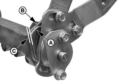
. . LEGEND:
AInner Level Pivot Plate
BFriction Plate
CParallel Alignment
DDraft-Sensing Rod
ELock Nut
REASON:
To ensure rockshaft draft system allows proper amount of implement control.
PROCEDURE:
[1] - Remove right-side fender.
[2] - Start engine.
[3] - Move outer control lever fully forward. Make sure there is no load on the rockshaft centerlink. Slowly move the inner lever rearward until the rockshaft arms just begin to rise. Stop engine.
[4] - At this point, check the position of the rear edge of the inner pivot plate (A). It should align parallel (C) with flat surface on rear of friction plate (B). If surfaces of lever and plate align as shown, no adjustment is necessary. If adjustment is necessary, continue with procedure.
[5] - Loosen rod end lock nut (E) on the draft-sensing rod (D). If lift arms move before plates align, shorten rod using wrenching flats on rod (D). If lift arms move after plates align, lengthen rod.
[6] - Repeat procedure until adjustment is correct. Make sure lock nut (E) is tightened securely.
[7]→NOTE:
With rockshaft completely raised and draft control lever fully rearward, system should not go into relief.
Install right-side fender.
Mid Mount Control Valve Joystick Cable Adjustment
. LEGEND:
ACable
BLock Nut
CAdjusting Nut
DSupport
EPin
FCotter Pin
GValve Spool
REASON:
To ensure that joystick returns to the neutral position.
PROCEDURE:
→NOTE:
If joystick does return to the center position from left to right (bottom valve) movement, adjust bottom cable on mid mount control valve.
If joystick does return to the center position from front to back (top valve) movement, adjust top cable on mid mount control valve
Section
[1] - Operate mid mount control valve joystick through all positions to relieve any pressure in the system.
[2] - Remove cotter pin (F) and pin (E).
[3] - Position the joystick lever in the center (neutral) position and engage lock lever located on the side of joystick column.
[4] - Loosen nut (B) and turn adjusting nut (C) to move cable (A) in or out of support (D) until hole in end cable (A) aligns with hole in valve spool (G).
[5] - Install pin (E) and cotter pin (F).
[6] - Tighten lock nut (B). Repeat procedure for remaining cable, if necessary.
Section
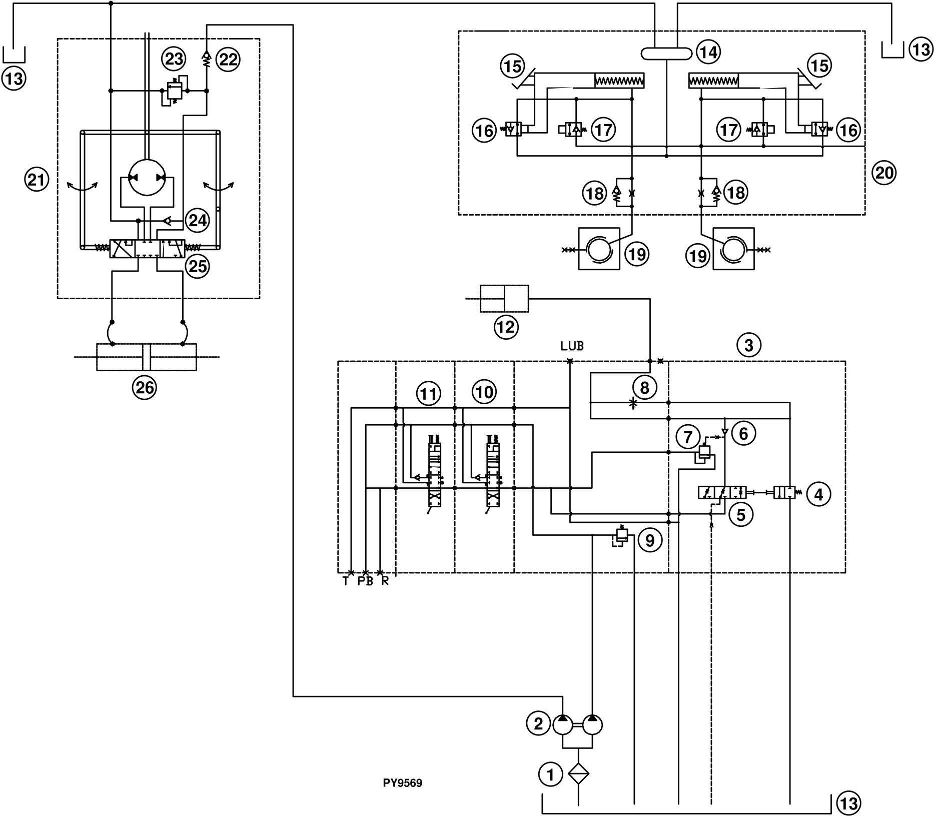
Group 45 - Hydraulic Schematics
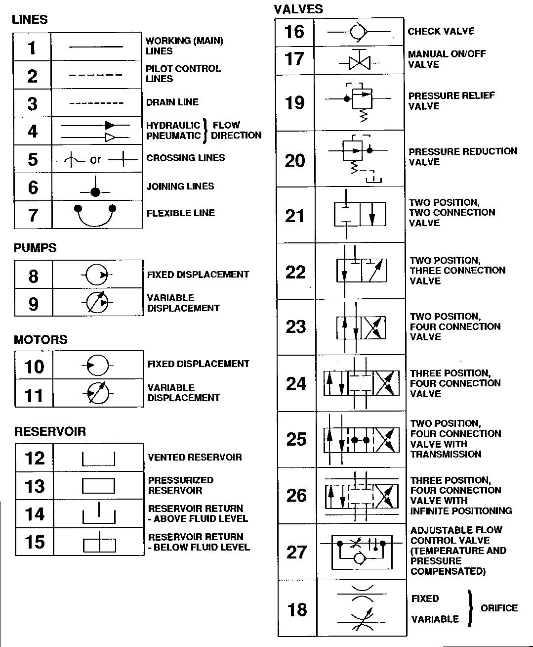
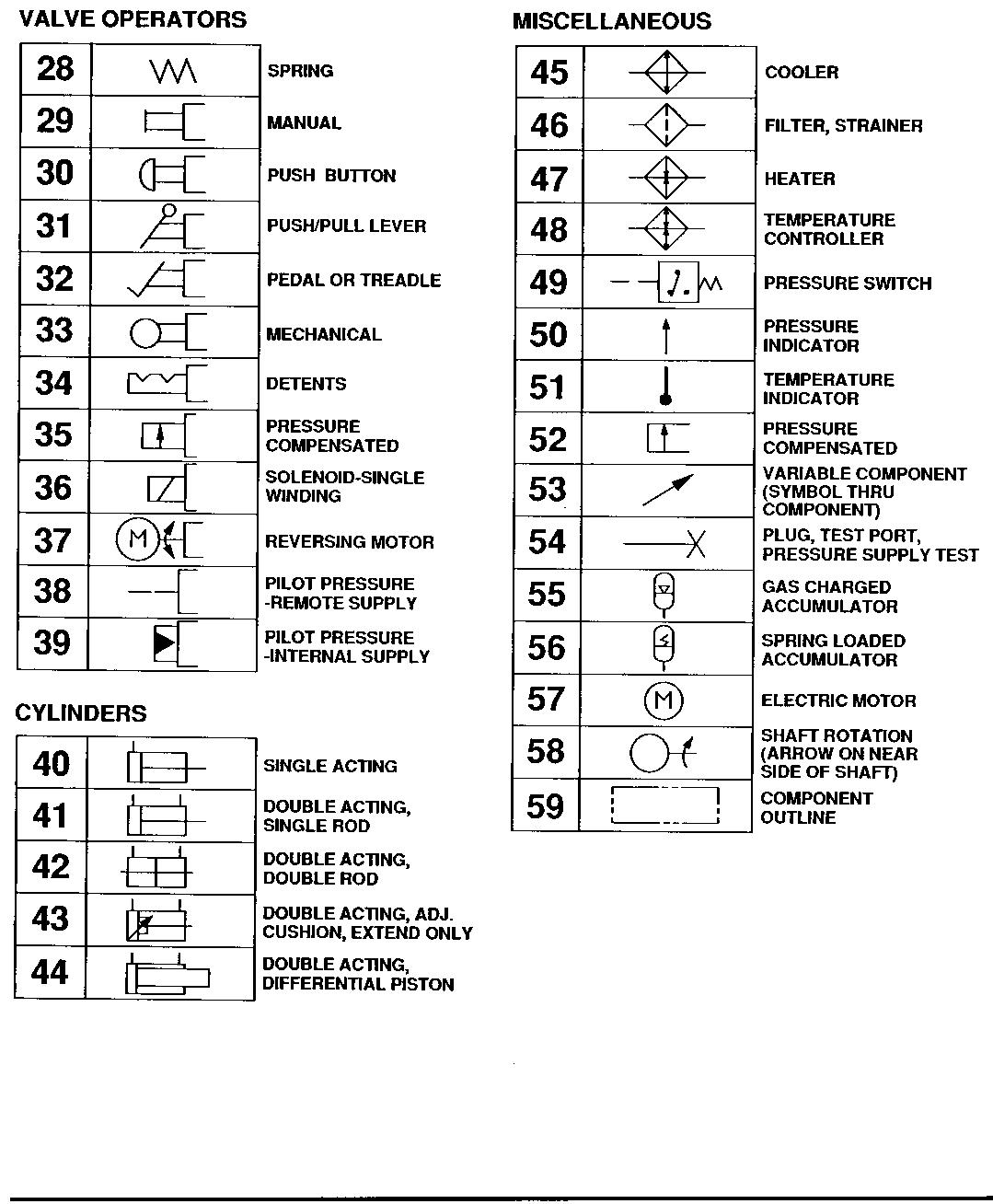
Hydraulic Circuit Symbols
Hydraulic Circuit Symbols
Hydraulic Circuit Symbols
Section
Hydraulic System—Standard Tractor with First and Second Rear SCV