This technical manual is written for an experienced technician and contains sections that are specifically for this product. It is a part of a total product support program.
The manual is organized so that all the information on a particular system is kept together. The order of grouping is as follows:
• Table of Contents
• Specifications
• Component Location
• System Schematic
• Theory of Operation
• Troubleshooting Chart
• Diagnostics
• Tests & Adjustments
• Repair
Note:Depending on the particular section or system being covered, not all of the above groups may be used.
Each section will be identified with a symbol rather than a number. The groups and pages within a section will be consecutively numbered.
We appreciate your input on this manual. To help, there are postage paid post cards included at the back. If you find any errors or want to comment on the layout of the manual please fill out one of the cards and mail it back to us.
All information, illustrations and specifications in this manual are based on the latest information available at the time of publication. The right is reserved to make changes at any time without notice.
COPYRIGHT© 2000 Deere & Co.
John Deere Worldwide Commercial and Consumer Equipment Division Horicon, WI All rights reserved
RECOGNIZE SAFETY INFORMATION
HANDLE FLUIDS SAFELY-AVOID FIRES
Be Prepared For Emergencies
This is the safety-alert symbol. When you see this symbol on your machine or in this manual, be alert to the potential for personal injury.
Follow recommended precautions and safe servicing practices.
Understand Signal Words
A signal word—DANGER, WARNING, or CAUTION— is used with the safety-alert symbol. DANGER identifies the most serious hazards.
DANGER or WARNING safety signs are located near specific hazards. General precautions are listed on CAUTION safety signs. CAUTION also calls attention to safety messages in this manual.
REPLACE SAFETY SIGNS
Replace missing or damaged safety signs. See the machine operator’s manual for correct safety sign placement.
When you work around batteries, do not smoke or work near heaters, sparks or other fire hazards.
Charge batteries in a well ventilated area.
Store flammable fluids away from fire hazards. Do not incinerate or puncture pressurized containers.
Make sure machine is clean of trash, grease, and debris.
Do not store oily rags; they can ignite and burn spontaneously.
Be prepared if a fire starts.
Keep a first aid kit and fire extinguisher handy.
Keep emergency numbers for doctors, ambulance service, hospital, and fire department near your telephone.
TS201
TS291
TS227
USE CARE IN HANDLING AND SERVICING BATTERIES
Prevent Battery Explosions
Batteries contain sulfuric acid and produce explosive mixtures of hydrogen and oxygen. Because selfdischarge action generates hydrogen gas even when the battery is not in operation, make sure batteries are stored and serviced in a well ventilated area.
• Always wear proper eye, face and hand protection.
• Keep sparks, lighted matches, and open flame away from the top of battery.
• Remove all jewelry (watches, rings, bracelets, etc.) before servicing the electrical system or batteries.
• Make sure work area is well ventilated.
• Never lean over battery while testing or charging.
• Keep removable vents tight and level except when servicing electrolyte.
• Exercise caution while working with metallic tools or conductors to prevent short circuits and sparks.
• Never check battery charge by placing a metal object across the posts. Use a battery tester, voltmeter or hydrometer.
• Do not charge a frozen battery; it may explode. Warm battery to 16°C (60°F).
Safe Charging
• Never attempt to charge a battery without first reviewing the instructions for the charger being used.
• Use only the battery charger provided with the utility vehicle. DO NOT use substitutes.
• Always wear proper eye, face and hand protection.
• Keep sparks, lighted matches, and open flame away from the top of battery.
• Make sure work area is well ventilated.
• Never lean over battery while testing or charging.
• Keep removable vents tight and level except when servicing electrolyte.
• To avoid dangerous sparks, Do not disconnect the DC output cord from the battery receptacle when the charger is on. Disconnect the AC power supply cord to turn the charger off before disconnecting the DC output plug.
• Never try to charge a visibly damaged or frozen battery.
• Be sure that the key switch and all electrical accessories are turned off.
• Make sure that the charger leads are not broken, frayed or loose.
• If the battery becomes hot, or if violent gassing or spewing of electrolyte occurs, unplug the charger AC source first before removing the DC plug
• If battery set is on charge, unplug the charger AC plug before disconnecting the charger DC cable plug to avoid dangerous sparks.
Prevent Acid Burns
Sulfuric acid in battery electrolyte is poisonous. It is strong enough to burn skin, eat holes in clothing, and cause blindness if splashed into eyes.
Use extreme caution when handling electrolyte and keep an acid neutralizing solution - such as baking soda or household ammonia mixed with water - readily available.
• Avoid acid burns by:
1. Filling batteries in a well-ventilated area.
2. Wearing eye and face protection a rubber apron and rubber gloves.
3. Avoiding breathing fumes when electrolyte is added.
4. Avoiding spilling or dripping electrolyte.
• If you spill acid on yourself:
1. Flush area of body that has been exposed with clean water for at least 20 minutes.
2. Remove contaminated clothing.
3. Flush your eyes with clean, cool water for at least 20 minutes.
4. Get medical attention immediately.
• If acid is swallowed:
1. Drink large amounts of water or milk. Do not induce vomiting.
2. Then drink milk of magnesia, beaten eggs, or vegetable oil.
3. Get medical attention immediately.
USE SAFE SERVICE PROCEDURES
Wear Protective Clothing
Wear close fitting clothing and safety equipment appropriate to the job.
Prolonged exposure to loud noise can cause impairment or loss of hearing. Wear a suitable hearing protective device such as earmuffs or earplugs to protect against objectionable or uncomfortable loud noises.
Operating equipment safely requires the full attention of the operator. Do not wear radio or music headphones while operating machine.
Use Proper Tools
Use tools appropriate to the work.
Use extreme caution when using tools, wires, or metal objects near batteries! A short circuit and/or spark could cause an electrical shock or an explosion. Wrap tools with vinyl tape to prevent shorting out battery(s).
Makeshift tools and procedures can create safety hazards. Use power tools only to loosen threaded parts and fasteners. For loosening and tightening hardware, use the correct size tools. DO NOT use U.S. measurement tools on metric fasteners. Avoid bodily injury caused by slipping wrenches. Use only service parts meeting John Deere specifications.
Park Machine Safely
Service Machines Safely
Tie long hair behind your head. Do not wear a necktie, scarf, loose clothing, or necklace when you work near machine tools or moving parts. If these items were to get caught, severe injury could result.
Remove rings and other jewelry to prevent electrical shorts and entanglement in moving parts.
Use Caution When Servicing Electrical System
Always use extreme caution when servicing this utility vehicle. This utility vehicle is equipped with a 48 volt electrical system capable of passing a high voltage electrical current.
Only persons trained in electrical maintenance should repair or service this utility vehicle.
Always move the service/drive switch to the SERVICE position before servicing any part of the electrical system.
Always refer to the battery position/connection diagram when making battery connections to avoid battery explosion. Disconnect the battery set positive (B+) cable before servicing the electrical system.
Before working on the machine:
1. Turn key switch to the OFF position and remove the key.
2. Move directional control lever to the NEUTRAL position.
3. Engage the park brake.
4. Raise and tilt operator seat forward. Move the service/drive switch to the SERVICE position.
5. Hang a “DO NOT OPERATE” tag in operator station.
TS230
Support Machine Properly And Use
Proper Lifting Equipment
Work In Clean Area
Before starting a job:
1. Clean work area and machine.
2. Make sure you have all necessary tools to do your job.
3. Have the right parts on hand.
4. Read all instructions thoroughly; do not attempt shortcuts.
Using High Pressure Washers
If you must work on a lifted machine or attachment, securely support the machine or attachment.
Do not support the machine on cinder blocks, hollow tiles, or props that may crumble under continuous load. Do not work under a machine that is supported solely by a jack. Follow recommended procedures in this manual.
Lifting heavy components incorrectly can cause severe injury or machine damage. Follow recommended procedure for removal and installation of components in the manual.
Directing pressurized water at electronic/electrical components or connectors, bearings, or other sensitive parts and components may cause product malfunctions. Reduce pressure and spray at a 45 to 90 degree angle.
Illuminate Work Area Safely
Illuminate your work area adequately but safely. Use a portable safety light for working inside or under the machine. Make sure the bulb is enclosed by a wire cage. The hot filament of an accidentally broken bulb can ignite hydrogen gases or spilled fuel or oil.
Work In Ventilated Area
Battery fumes can cause sickness or death. Make sure the work area is well ventilated if it is necessary to charge the batteries in an enclosed area.
SPECIFICATIONS
GENERAL SPECIFICATIONS
TRANSAXLE
Nominal Travel Speed-Forward.
Nominal Travel Speed-Reverse.
Transaxle Capacity
TORQUE SPECIFICATIONS
Brake Bolts
Cover Plate Screws.
Differential Bearing Cap
Fill Plug.
Final Drive Gear Bolts.
Spindle Nut
Transaxle Mounting Carriage Bolts.
OTHER MATERIALS
HYDRAULIC OIL JDM J20C Hy-GARD
LOCTITE PRODUCTS
U.S./ Canadian/ LOCTITE No.
NumberNameUse
.25 km/h (15.5 mph)
km/h (9 mph)
0.4 L (15 oz)
(17 lb-ft)
N•m (20 lb-ft)
55 N•m (40 lb-ft)
47 N•m (35 lb-ft)
(40 lb-ft)
TY6333/Moly High Temperature EP GreaseApply to splines of axle.
TY6333/
TY6305/Clean and Cure PrimerClean transaxle case mating surfaces.
TY9485/ 764
TY16135/Flexible SealantSeal transaxle case.
TY15705/ 518
LOCTITE is a registered trademark of the Loctite Corp.
TRANSAXLE COMPONENTS
M94889
Capscrew
AXLE COMPONENTS
Axle Housing Tube Assembly
Cap Screw (4 Used)
23 N•m (17 lb-ft)
Wheel Bearing Retainer Retaining Ring
Ball Bearing Snap Ring
Studs (5 Used)
Lock Nut
Brake Assembly
Snap Ring
Left Axle
Brake Drum
Wheel
M94888
THEORY OF OPERATION
Function:
The transaxle provides a means of transferring power from the electric motor to the input shaft to the gear drive components of the transaxle and ultimately the drive wheels.
Speed and directional control is provided by the electric motor.
TRANSAXLE REMOVAL & INSTALLATION
Removal:
1. Park vehicle on a hard level surface.
2. Turn key switch to the OFF position.
3. Move the directional control lever to the NEUTRAL position.
4. Block the front wheels to prevent the vehicle from rolling when the rear axle is raised off of the ground.
5. Raise and tilt operators seat up and forward to gain access to the service/drive switch.
6. Place the service/drive switch in the service position.
7. Raise the cargo bed and secure the prop rod.
12. Remove the six capscrews (A) securing the cover to the frame.
13. Tip the top of the cover down to unhook the cover from the center bracket (B) and pull the cover out and away from the vehicle.
14. Remove the electric motor. See ELECTRIC MOTOR SECTION “MOTOR REMOVAL & INSTALLATION” on page9.
8. Note the position of each battery and the location of both the positive and negative terminals.
9. Using insulated tools and care not to touch wrench to other terminals or the frame of the vehicle, disconnect the battery pack positive wires.
10. Remove the batteries. See BATTERIES SECTION “BATTERY REPLACEMENT” on page17. Steps 1 through 11.
11. Remove the cargo bed. See MISC. SECTION “CARGO BOX REMOVAL & INSTALLATION” on page8.
15. Remove the nine carriage bolts securing the hitch to the vehicle. There are three (C) bolts through the frame cross member, four (D) bolts fastening the hitch to the axle, and two (E) fastening the hitch to the rear support bracket.
16. Pull the hitch assembly down and out the rear of the vehicle.
17. Raise and support machine so that the rear wheels are just off the ground. Place the support under the frame rails just in front of the rear axle mounting plates.
18. Remove five lug nuts on each wheel and remove the wheels.
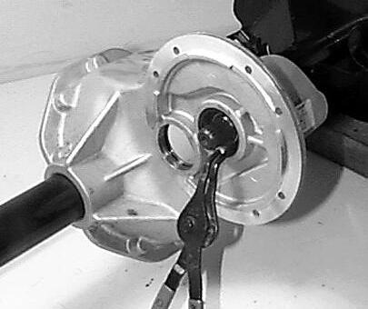
19. On each brake drum assembly, remove the cotter pin (F) and clevis pin (G) the fasten the brake cable (H) to the brake actuator arm (I).
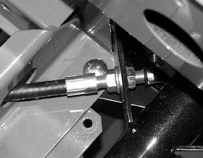
20. Loosen the brake cable retainer nuts (J) and pull the brake cable (H) out of the axle mounting bracket (K).
21. Remove the lower mounting carriage bolt (L) on each side.
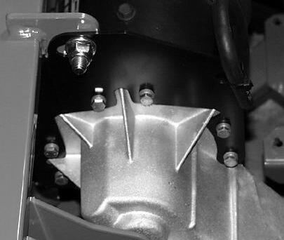
22. Remove the vent tube from the torque plate by cutting the tie wrap (M).
23. Remove the carriage bolt (N) securing the torque plate (O) to the frame.
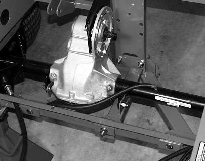
24. Place a floor jack (P) under the differential case (Q) to support the transaxle when the last carriage bolts are removed.
25. Remove the remaining four (two on each side) carriage bolts (R) that secure the transaxle to the frame rails.
26. Support the axle out at the brake drums (S) and slowly lower the floor jack (P) until the transaxle can be pulled out from under the frame.
Installation is done in reverse order.
Specification:
Carriage Bolts
AXLE SHAFT REMOVAL & INSTALLATION
Removal:
1. Remove fill plug on bottom of differential cover and drain oil. Capacity is 0.4 L (15 oz).
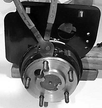
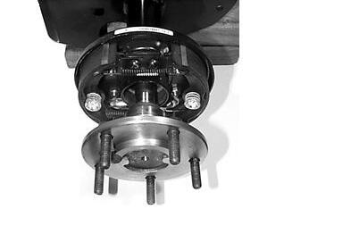
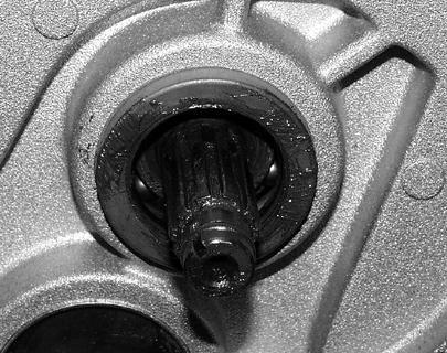
2. Remove snap ring from end of tube.
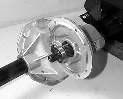
3. Using a slide hammer if needed, remove the axle shaft (A) from the axle tube.
4. Remove four bolts (B) holding brake assembly (C) on axle tube (D).
5. Remove brake assembly (C) from the axle tube (D).
M99900
6. Remove the inner snap ring (E).
7. Use a slide hammer to remove the oil seal (F).
IMPORTANT: Use caution as not to damage the seal seating surface.
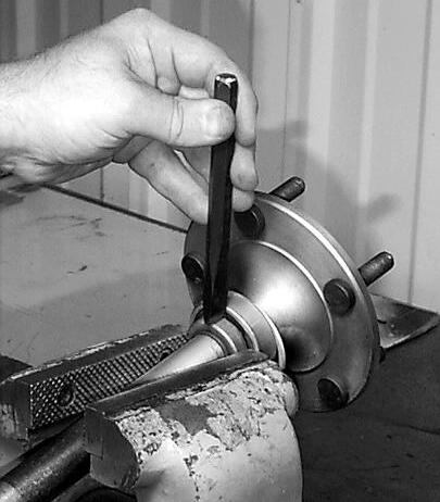
8. Place the axle shaft (A) in a vise and center punch the outside of the retaining ring (G) on the axle shaft.
9. Drill the retaining ring (G) with a 1/4” drill, approximately 3/4 of the depth of the retaining ring.
IMPORTANT: Drilling completely through the retaining ring will damage the shaft.
10. Position a chisel across the hole and strike sharply to break the retaining ring (G).
11. Support the axle shaft in a suitable press. Press on the end of the shaft until the wheel bearing (H) is removed. Use caution as not to damage the shaft splines.
12. Inspect the axle shafts for worn splines, bends, or cracks.
13. Replace these parts if they show signs of damage or wear.
M99851
M99853
Installation:
1. Place the snap ring over the shaft and the press the bearing onto the shaft.
IMPORTANT: Use caution as not to damage the shaft splines.
2. Support the axle shaft in a suitable press. Support the bearing (H) on the inner ring to avoid damage to the bearing. Press shaft into bearing until the bearing is firmly seated against the shoulder. Use caution as not to damage the shaft splines.
3. Press a new retaining ring (G) firmly against the bearing.
4. Press a new oil seal (F) into the axle shaft tube to a depth of 28.5 mm (1.125 in.).
5. Install inner snap ring (E).
6. Grease the lip of the seal (F) with a light coating of Moly EP grease.
7. Check the axle shaft including the splines for any nicks or burrs. Using emory cloth, lightly sand any minor defects smooth.
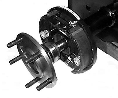
8. Position brake assembly (C) on axle tube (D) with the brake shoes (I) facing out and the brake adjuster (J) to the bottom. Secure to the axle tube with four capscrews (B) and tighten to 23 N•m (17 lb-ft).
9. Install the axle shaft (A) into the axle tube (D), being careful not to damage the oil seal (F) when sliding the shaft into the carrier.
10. Install the snap ring into the groove in the tube to secure the axle shaft into the axle tube.
11. Refill the differential gear case with 0.4 L (15 oz) of JDM J20C Hy-Gard oil.
Specification:
Brake Assembly Capscrews. . .
M99851
M99854
DIFFERENTIAL CASE
DISASSEMBLY & ASSEMBLY
Disassembly:
1. Remove fill plug on bottom of differential cover and drain oil. Capacity is 0.4 L (15 oz).
2. Remove both the left and right axle shafts.
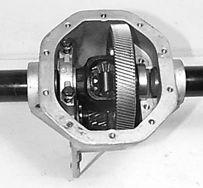
3. Remove the ten capscrews holding the cover plate to the gear case.
4. Using a putty knife, separate the cover from the housing. Use caution as not to damage the housing sealing surface (A) or deform the cover plate.
remove the bearing caps (C).
NOTE: Bearing caps are marked for identification. Letters or numbers are stamped in horizontal and vertical position. During reassembly, place them back in their original positions. case (E).
7. Using a bearing puller, remove the differential bearings (F) from each side of the differential gear assembly.
8. Remove the four capscrews and nuts from the final drive gear. Remove gear from differential gear assembly, using caution not to damage gear teeth.
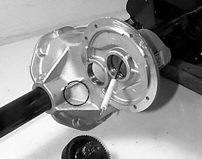
9. Punch or drill approximately a 1/8” diameter hole near the center of each intermediate bore plug (G).
10. Insert a suitably sized sheet metal screw into the plug to force the plug out of the bore.
11. Remove the snap ring from each side of the intermediate bore.
12. From the flange side (H) of the differential housing, push the intermediate shaft (I) over far enough to engage an ID bearing puller into bearing. Use a brass drift pin if needed.
13. Using a ID bearing puller attached to a slide hammer, remove intermediate bearing from flange side of housing.
M99856
M99855
M99857
NOTE: If there is no response to click on the link above, please download the PDF document first and then clickonit.
14. Remove the bearing on the opposite side of the housing as in the previous step.
IMPORTANT: Shaft and gear assembly must be supported by hand as not to damage gear teeth. Small end of intermediate shaft and gear assembly must be tilted toward opening in bottom of housing for removal. Use caution not to damage gear teeth.
15. Remove the O-ring (J) from the end of the input shaft.
16. Remove the oil seal (K) from the bore of the input shaft and replace with a new seal during reassembly.
17. Remove snap ring (L) from input shaft (M) bore.
18. Pull input shaft (M) assembly from housing. The input shaft assembly should slide out of the housing easily. If resistance is encountered, a slide hammer may be required. Use caution as not to damage gear.
19. Using a bearing puller, remove the bearings (N) from the input shaft (M). Use caution as not to damage gear.
20. Remove the O-rings (O) from the outer input bearing bore (P) , and both intermediate bearing bores (Q).
21. Remove the O-rings (R) at each end of intermediate shaft (I) on the bearing shoulders (S).
M99962
M99860
22. Clean all parts with a petroleum based cleaner.
23. Dry parts using a soft, lintless towel or rag after cleaning. Bearings should NOT be dried by spinning with compressed air. This can damage mating surfaces due to lack of lubrication.
24. After drying, parts should be coated with a light coat of lubricant or rust preventative to prevent damage from corrosion. If parts are to be stored for a prolonged period they should be wrapped.
25. Inspect parts for signs of wear of damage. Bearing and seal surfaces should be inspected for pitting, wear, or overheating. Inspect gears for pitting, wear or scoring.
26. Replace any parts that show signs of damage or wear.
Installation:
1. Wipe new O-rings (O) with a light coating of oil.
2. Install new O-rings into the outer input bearing bore (P).
3. Press new bearing onto input shaft until seated against bearing shoulder.
4. Install input shaft (M). Bearings and shaft should slide easily into housing. If resistance is encountered, the bearing and shaft assembly may be cocked slightly in the bore. Try to reposition the assembly with gentle rocking of the bearing and shaft assembly. If resistance is still encountered, a plastic or leather mallet could be used to gentle tap the shaft into its correct position.
Install snap ring (K) into the input shaft bore (L).
6. Install new O-ring (J) onto the end of the input shaft.
7. Install a new oil seal (K) into the bore of the input shaft until it is lightly seated against the shoulder in the bore.
5.
M99858
M99860
M99859
M99962
8. Install new O-ring (N) into both intermediate bearing bores (T).
9. Install new O-rings (Q) on both sides of the intermediate shaft (I).
10. Install intermediate shaft (I). Tip small end of intermediate shaft and gear assembly toward bottom opening until bearing trunnion visually engages intermediate bores (T).
11. Align both bearing trunnions with intermediate bore.
12. Continue supporting intermediate shaft and gear assembly with one hand and insert the flanged side (H) bearing into opening. To seat the bearing past O-ring, a leather or plastic mallet may be required.
13. After the bearing is seated past the snap ring groove, install the snap ring.
14. Repeat this procedure for the opposite side bearing and install snap ring.
15. Clean the housing and new bore plugs surfaces using TY6305 or TY9485 Clean and Cure Primer. (LOCTITE 764)
16. Place a small film of TY16135 or TY15705 Flexible Sealant, (LOCTITE 518), to bore plug sealing surface.
17. Using a properly sized driver and hammer, install bore plugs into housings until plug bottoms in bore.
18. Install the final drive gear onto the differential gear assembly.
19. Install the four capscrews from the flanged side of the differential gear. Tighten using the four nuts to 55 N•m (40 lb-ft)
20. Install the differential bearings on the differential gear assembly until firmly seated against bearing shoulder.
21. Insert differential gear assembly (D) into housing (E).
M99858
M99855