John Deere 750C 850C Crawler Dozer Diagnostic TM1588
750C, 850C Crawler Dozer Diagnostic
OPERATION AND TEST MANUAL
Dozer models 750C, 850C
TM1588 05 MAR 07 (ENGLISH)
For complete service information also see: 750C, 850C Crawler Dozer Repair
PowerTech 8.1 L Diesel Engines Base Engine
Electronic Fuel Injection Systems
Series 400, 6076 Diesel Engines
Super Caddy Oil Cleanup Procedure
PowerTech 8.1L Diesel Engines Mechanical Fuel Systems
PowerTech 6.8L and 8.1L, 6068 and 6081 Diesel Engines (Level 3 Electronic Fuel Systems with Bosch In-Line Pump)
PowerTech 4.5L & 6.8L Diesel Engines
Tier 1/Stage I, Tier 2/Stage II, Tier 3/Stage IIIA, Tier 3/Stage IIA Tier 3/Stage III, (Base Engine)
Ultrasonic Undercarriage Measurement Gauge
TM1589
CTM86
CTM68
CTM42
CTM310
CTM243
CTM134
CTM104
CTM10001
John Deere Construction and Forestry
Table of contents
FOREWORD
TECHNICAL INFORMATION FEEDBACK FORM
Section 9000 - GENERAL INFORMATION
Group 01 - Safety
Group 02 - General Speci cations
Group 03 - Torque Values
Group 04 - Fuels and Lubricants
Section 9005 - OPERATIONAL CHECKOUT PROCEDURE
Group 10 - Operational Checkout Procedure
Section 9010 - ENGINE
Group 05 - Theory of Operation
Group 10 - System Operational Checks
Group 15 - Diagnostic Information
Group 20 - Adjustments
Group 25 - Tests
Section 9015 - ELECTRICAL SYSTEM
Group 05 - System Information
Group 10 - System Diagrams
Group 15 - Sub-System Diagnostics
Group 20 - TCU Calibration and Diagnostics
Group 35 - References
Section 9020 - POWER TRAIN
Group 05 - Theory of Operation
Group 10 - System Operational Checks
Group 15 - Diagnostic Information
Group 20 - Adjustments
Section 9025 - HYDRAULICS
Group 05 - Theory
Group 15 - Diagnostic Information
Group 25 - Tests
Section 9026 - HYDROSTATIC SYSTEM
Group 05 - Theory of Operation
Group 10 - System Operational Checks
Group 15 - Diagnostic Information
Group 20 - Adjustments
Group 25 - Tests
Section 9031 - HEATING AND AIR CONDITIONING
Group 05 - Theory of Operation
Group 10 - System Operational Checks
Group 15 - Diagnostic Information
Group 20 - Adjustments
Group 25 - Tests
Foreword
This manual is written for an experienced technician. Essential tools required in performing certain service work are identi ed in this manual and are recommended for use.
Live with safety: Read the safety messages in the introduction of this manual and the cautions presented throughout the text of the manual.
CAUTION:
This is the safety-alert symbol. When you see this symbol on the machine or in this manual, be alert to the potential for personal injury.
Technical manuals are divided in two parts: repair and operation and tests. Repair sections tell how to repair the components. Operation and tests sections help you identify the majority of routine problems quickly.
Information is organized in groups for the various components requiring service instruction. At the beginning of each group are summary listings of all applicable essential tools, service equipment and tools, other materials needed to do the job, service parts kits, speci cations, wear tolerances, and torque values.
Technical Manuals are concise guides for speci c machines. They are on-the-job guides containing only the vital information needed for diagnosis, analysis, testing, and repair.
Fundamental service information is available from other sources covering basic theory of operation, fundamentals of troubleshooting, general maintenance, and basic type of failures and their causes.
Technical Information Feedback Form
We need your help to continually improve our technical publications. Please copy this page and FAX or mail your comments, ideas and improvements.
Technical Manual Fax
SENDTO: John Deere Dubuque Works P.O. Box 538
Attn: Publications Supervisor, Dept. 303
Dubuque, IA 52004-0538
FAXNUMBER: 563-589-5800
Ideas, Comments (Please State Page Number):
OVERALL, how would you rate the quality of this publication? (Check one)
Company Name:
Technician Name:
Address: Phone:
Group 01 - Safety
Handle Fluids Safely Avoid Fires
Avoid Fires
When you work around fuel, do not smoke or work near heaters or other re hazards.
Store ammable uids away from re hazards. Do not incinerate or puncture pressurized containers.
Make sure machine is clean of trash, grease, and debris.
Do not store oily rags; they can ignite and burn spontaneously.
Prevent Battery Explosions
Battery Explosions
Keep sparks, lighted matches, and open ame away from the top of battery. Battery gas can explode.
Never check battery charge by placing a metal object across the posts. Use a volt-meter or hydrometer.
Do not charge a frozen battery; it may explode. Warm battery to 16°C (60°F).
Prepare for Emergencies
First Aid Kit
Be prepared if a re starts.
Keep a rst aid kit and re extinguisher handy.
Keep emergency numbers for doctors, ambulance service, hospital, and re department near your telephone.
Prevent Acid Burns
Sulfuric acid in battery electrolyte is poisonous. It is strong enough to burn skin, eat holes in clothing, and cause blindness if splashed into eyes.
Avoid the hazard by:
Filling batteries in a well-ventilated area.
Wearing eye protection and rubber gloves.
Avoiding breathing fumes when electrolyte is added.
Avoiding spilling or dripping electrolyte.
Use proper jump start procedure.
If you spill acid on yourself:
Flush your skin with water.
Apply baking soda or lime to help neutralize the acid.
Flush your eyes with water for 15 30 minutes. Get medical attention immediately.
If acid is swallowed:
Do not induce vomiting.
Drink large amounts of water or milk, but do not exceed 2 L (2 quarts).
Get medical attention immediately.
Acid Burns
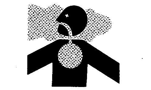
Handle Chemical Products Safely
Handle Chemical Products Safely
Direct exposure to chemical products can cause severe skin irritation and injury. Hazardous fumes can be generated when handling the chemicals.
Wear close tting clothing and a face mask when handling chemicals. Dispose of chemical waste and packaging material properly.
A Material Safety Data Sheet provides speci c details on chemical products and physical dangers, safety procedures, and emergency response techniques. User awareness and training is required under U.S. workplace and environmental laws. See your John Deere dealer for information on chemical products used with John Deere equipment.
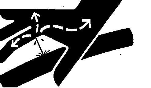
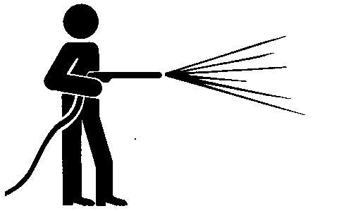
Avoid High-Pressure Fluids
High-Pressure Fluids
Escaping uid under pressure can penetrate the skin causing serious injury. Avoid the hazard by relieving pressure before disconnecting hydraulic or other lines. Tighten all connections before applying pressure.
Search for leaks with a piece of cardboard. Protect hands and body from high pressure uids.
If an accident occurs, see a doctor immediately. Any uid injected into the skin must be surgically removed within a few hours or gangrene may result. Doctors unfamiliar with this type of injury should reference a knowledgeable medical source. Such information is available from Deere & Company Medical Department in Moline, Illinois, U.S.A.
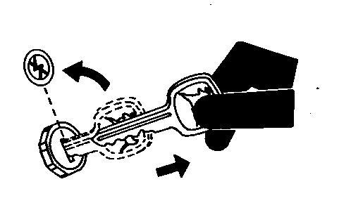
Park Machine Safely
Remove the Key
Before working on the machine:
Lower all equipment to the ground. Stop the engine and remove the key. Disconnect the battery ground strap. Hang a "DO NOT OPERATE" tag in operator station.
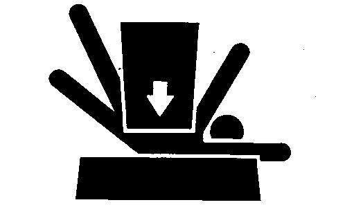
Support Machine Properly
Support Properly
Always lower the attachment or implement to the ground before you work on the machine. If the work requires that the machine or attachment be lifted, provide secure support for them. If left in a raised position, hydraulically supported devices can settle or leak down.
Do not support the machine on cinder blocks, hollow tiles, or props that may crumble under continuous load. Do not work under a machine that is supported solely by a jack. Follow recommended procedures in this manual. When implements or attachments are used with a machine, always follow safety precautions listed in the implement or attachment operator s manual.
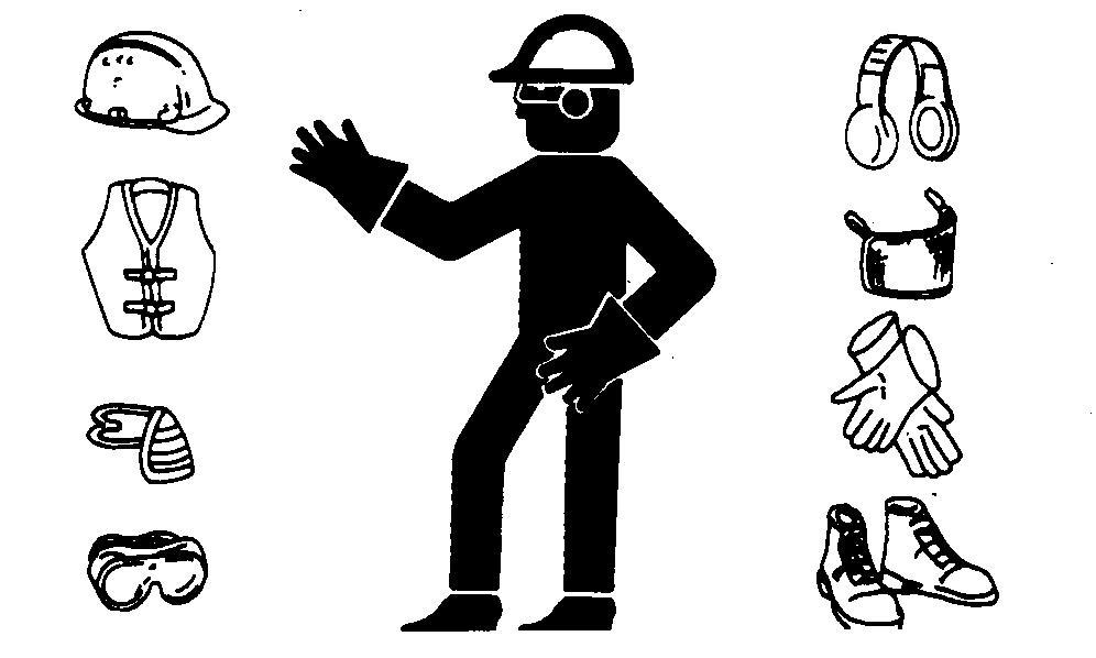
Wear Protective Clothing
Protective Clothing
Wear close tting clothing and safety equipment appropriate to the job.
Prolonged exposure to loud noise can cause impairment or loss of hearing.
Wear a suitable hearing protective device such as earmu s or earplugs to protect against objectionable or uncomfortable loud noises.
Operating equipment safely requires the full attention of the operator. Do not wear radio or music headphones while operating machine.
Work in Clean Area
Before starting a job:
Clean work area and machine. Make sure you have all necessary tools to do your job. Have the right parts on hand. Read all instructions thoroughly; do not attempt shortcuts.
Service Machines Safely
Moving Parts
Tie long hair behind your head. Do not wear a necktie, scarf, loose clothing, or necklace when you work near machine tools or moving parts. If these items were to get caught, severe injury could result.
Remove rings and other jewelry to prevent electrical shorts and entanglement in moving parts.
Work In Ventilated Area
Engine exhaust fumes
Engine exhaust fumes can cause sickness or death. If it is necessary to run an engine in an enclosed area, remove the exhaust fumes from the area with an exhaust pipe extension.
If you do not have an exhaust pipe extension, open the doors and get outside air into the area
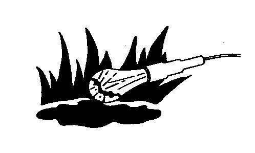
Illuminate Work Area Safely
Work Area Safely
Illuminate your work area adequately but safely. Use a portable safety light for working inside or under the machine. Make sure the bulb is enclosed by a wire cage. The hot lament of an accidentally broken bulb can ignite spilled fuel or oil.
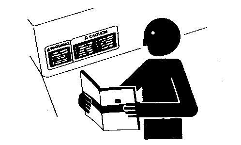
Replace Safety Signs
Safety Signs
Replace missing or damaged safety signs. See the machine operator s manual for correct safety sign placement.
Use Proper Lifting Equipment
Lifting heavy components incorrectly can cause severe injury or machine damage.
Follow recommended procedure for removal and installation of components in the manual.
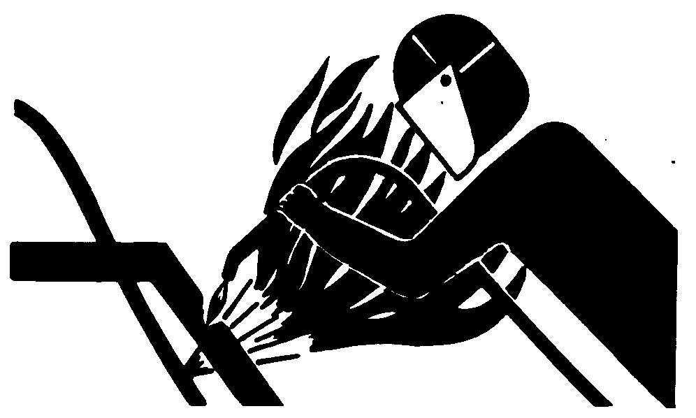
Remove Paint Before Welding or Heating
Toxic Fumes
Avoid potentially toxic fumes and dust.
Hazardous fumes can be generated when paint is heated by welding, soldering, or using a torch.
Remove paint before heating:
Remove paint a minimum of 100 mm (4 in.) from area to be a ected by heating. If paint cannot be removed, wear an approved respirator before heating or welding. If you sand or grind paint, avoid breathing the dust. Wear an approved respirator. If you use solvent or paint stripper, remove stripper with soap and water before welding. Remove solvent or paint stripper containers and other ammable material from area. Allow fumes to disperse at least 15 minutes before welding or heating.
Do not use a chlorinated solvent in areas where welding will take place.
Do all work in an area that is well ventilated to carry toxic fumes and dust away.
Dispose of paint and solvent properly.
Avoid Heating Near Pressurized Fluid Lines
Flammable Spray
Flammable spray can be generated by heating near pressurized uid lines, resulting in severe burns to yourself and bystanders. Do not heat by welding, soldering, or using a torch near pressurized uid lines or other ammable materials. Pressurized lines can accidentally burst when heat goes beyond the immediate ame area.
Keep ROPS Installed Properly
Roll-Over Protective Structure
Make certain all parts are reinstalled correctly if the roll-over protective structure (ROPS) is loosened or removed for any reason. Tighten mounting bolts to proper torque.
The protection o ered by ROPS will be impaired if ROPS is subjected to structural damage, is involved in an overturn incident, or is in any way altered by welding, bending, drilling, or cutting. A damaged ROPS should be replaced, not reused.
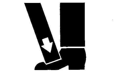
Keep Area Clean
Understand service procedure before doing work. Keep area clean and dry.
Never lubricate, service, or adjust machine while it is moving. Keep hands, feet , and clothing from power-driven parts. Disengage all power and operate controls to relieve pressure. Lower equipment to the ground. Stop the engine. Remove the key. Allow machine to cool.
Securely support any machine elements that must be raised for service work.
Keep all parts in good condition and properly installed. Fix damage immediately. Replace worn or broken parts. Remove any buildup of grease, oil, or debris.
On self-propelled equipment, disconnect battery ground cable (-) before making adjustments on electrical systems or welding on machine.
On towed implements, disconnect wiring harnesses from tractor before servicing electrical system components or welding on machine.
Dispose of Waste Properly
Recycle Waste
Improperly disposing of waste can threaten the environment and ecology. Potentially harmful waste used with John Deere equipment include such items as oil, fuel, coolant, brake uid, lters, and batteries.
Use leakproof containers when draining uids. Do not use food or beverage containers that may mislead someone into drinking from them.
Do not pour waste onto the ground, down a drain, or into any water source.
Air conditioning refrigerants escaping into the air can damage the Earth s atmosphere. Government regulations may require a certi ed air conditioning service center to recover and recycle used air conditioning refrigerants.
Inquire on the proper way to recycle or dispose of waste from your local environmental or recycling center, or from your John Deere dealer.
Live With Safety
Safety Systems
Before returning machine to customer, make sure machine is functioning properly, especially the safety systems. Install all guards and shields.
Group 02 - General Specifications
750C Speci cations
NOTE:
Speci cations and design subject to change without notice. Wherever applicable, speci cations are in accordance with ICED and SAE standards. Except where otherwise noted, these speci cations are based on a unit equipped with 560 mm (22 in.) grousers, roll-over protective canopy, full fuel tank, 79 kg (175 lb) operator, and standard equipment.
Net engine power is with standard equipment including air cleaner, exhaust system, alternator, and cooling fan, at standard conditions per SAE J1349 and DIN 6270B using No. 2-D fuel at 35 API gravity. No derating is required up to 3050 m (10,000 ft) altitude. Gross power is without cooling fan.
Item
Measurement Speci
John Deere 6-Cylinder Turbocharged Diesel Engine 6068T (S.N. 831315)
Rated Power at 2100 rpm Power 104 kW (140 hp) SAE net horsepower 110 kW (148 hp) SAE gross horsepower
Bore and Stroke
x 127 mm (4.14 x 5 in.)
Piston Displacement 6.785 L (414 cu in.)
Electrical System
24-volt with 45-amp alternator
Maximum Net Torque at 1300 rpm Torque Rise 570 N m (420 lb-ft)
Batteries Voltage Two 12-volt
Cold Cranking Amps 625 amps each at 18°C (0°F) Reserve Capacity 160 minutes each at 18°C (0°F)
Transmission Speed In nite from 0 11 km/h (0 6.8 mph) forward and reverse
Drawbar Pull at 1.9 km/h (1.2 mph)
Hydraulic System (Open Center) Pressure
Rate
Undercarriage
750C Track Shoes (Each Side) Quantity
750C LGP Track Shoes (Each Side)
750C Ground Contact Area (with 22 in. Shoes)
750C WT Ground Contact Area (with 34 in. Shoes)
750C minimum with single-bar grouser (excluding grouser height)
750C WT minimum with swamp shoe (including grouser height)
Ground Pressure
790 kPa (2000 psi)
L/min (38 gpm) at 2100 rpm
952 cm 2 (4488 sq in.)
750C with Semi-U Blade (High Production)
750C All-Hydraulic Dozer (PAT)
750C with Semi-U Blade (Low Pro le)
750C with Straight Blade (S.N. 883331)
750C with Angle Dozer (S.N. 883331)
750C WT with Straight Blade
750C LGP All-Hydraulic Dozer (PAT)
750C Capacity Speci cations
Drain and Re ll Capacities
15
14
WT Inner Final Drive (Each Side)
LGP Inner Final Drive (Each Side)
750C General Speci cations
Lubrication:
Pressure system with full ow lters
Cooling:
Pressured with thermostat and controlled bypass
Fan:
Blower-type
Air Cleaner:
Dual-stage aspirated with restriction indicator
Dry
Transmission:
Automatic, dual-path hydrostatic drive.
Load sensing feature automatically adjusts speed and power to match changing load conditions.
Dual path hydrostatic drive.
Live power turns: Both tracks remain fully powered during turns. This a ords greater maneuverability with larger loads and less ground disturbance. This feature also provides improved capability for working on soft ground, as well as the ability to counterbalance blade corner loads when benching, ditching or back lling.
Counter-rotation: Separate control allows the two transmissions to be driven in opposite directions, permitting spot turns with excellent maneuverability. Quick blade position changes can be made.
In nite speed selection: In nitely variable ground speeds, from 0 11 km/h (0 6.8 mph), allow precise speed. Speed can be reduced without slowing engine rpm, so hydraulic power remains high and response time remains fast.
Automatic load sensing: As a load increases and engine rpm lessens, the transmission automatically reduces ground speed to match load changes. This feature works at all throttle settings, providing full drawbar pull even at reduced engine speed.
Dynamic braking: Positive speed reduction is provided on slopes. When shifted to neutral, oil ow between the pump and motor is blocked. The crawler stops without use of the service brakes.
Steering:
Single lever steering and direction control with decelerator or optional steering pedals and U-pattern FNR lever without
decelerator, full power turn, counter-rotation and in nitely variable track speeds provide unlimited maneuverability and optimum control.
Hydrostatic steering eliminates the need for steering clutches and steering brakes as well as the need for cross-steering when working on steep slopes.
Brakes:
Hydrostatic (dynamic) braking stops the machine when the direction/steering control lever is moved to neutral. Wet-disk brakes are automatically applied when engine is stopped or manually applied with center foot pedal during normal operation.
Hydraulics:
Open center system 10 micron lter in return line with bypass Gear-type pump
Forestry Application:
The dozer can be equipped for forestry applications with the addition of limb risers and screens for the roll-over protective structure.
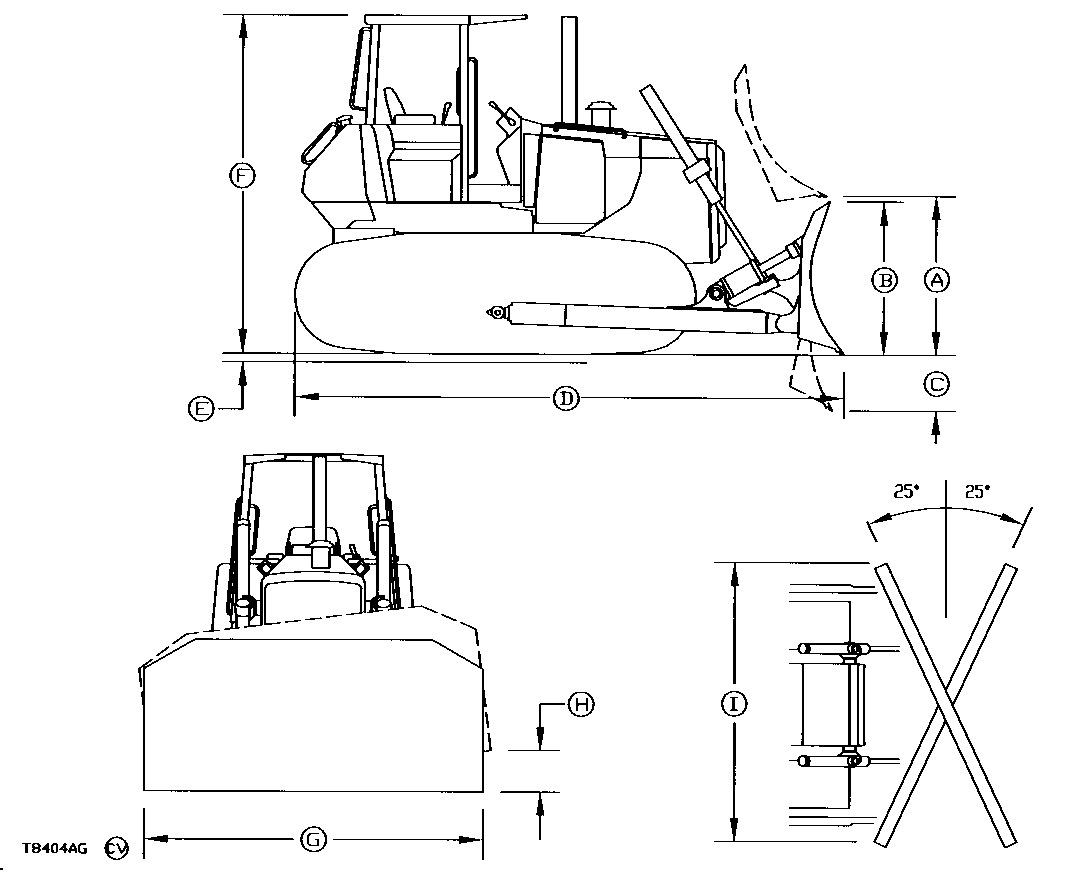
750C with Semi-U (High-Production) Blade:
B Blade
C Digging
E Tread
Grouser (Moderate
E Tread Depth with Single-Bar Grouser (Extreme Duty)
F Overall Machine
G Blade
H Maximum Blade Tilt
750C All-Hydraulic Dozer (PAT):
C Digging
D Overall Machine (with standard drawbar)
E Tread Depth with Single-Bar Grouser (Moderate Duty)
E Tread Depth with Single-Bar Grouser (Extreme Duty)
F Overall Machine
G Blade
H Maximum Blade Tilt
I Overall Blade Width (with Blade Angled)
750C with Semi-U (Low Pro le) Blade:
B Blade
C Digging
D Overall Machine
E Tread Depth with Single-Bar Grouser (Moderate Duty)
E Tread Depth with Single-Bar Grouser (Extreme Duty)
F
G
H
750C with Straight Blade:
A
B
C Digging
D Overall Machine
E Tread Depth with Single-Bar Grouser (Moderate Duty)
E Tread Depth with Single-Bar Grouser (Extreme Duty)
G Blade
H Maximum Blade Tilt
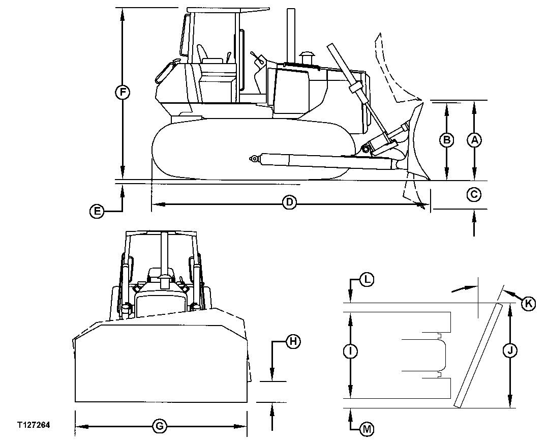
750C with Angle Dozer:
A Blade Lift
B
C Digging
D Overall Machine
E Tread Depth with Single-Bar Grouser (Moderate Duty)
E Tread Depth with Single-Bar Grouser (Extreme Duty)
F Overall Machine
G Blade
H Maximum Blade Tilt
I Overall Blade Width (with Blade Angled)
WT with Straight Blade: Blade
A Blade Lift
B Blade
C Digging
D Overall Machine
E Tread Depth with Single-Bar Grouser (Moderate Duty)
E Tread Depth with Swamp Shoe
F Overall Machine
G Blade
H Maximum Blade Tilt
750C LGP Dimensions
750C LGP All-Hydraulic Dozer (PAT):
A Blade Lift
B Blade
C Digging
D Overall Machine
E Tread Depth with Single-Bar Grouser (Moderate Duty)
F Overall Machine
G Blade
H Maximum Blade Tilt
I Overall Blade Width (with Blade Angled)
750C LT Series II Dimensions
750C LT Series II with Semi-U (High-Production) Blade:
B Blade
C Digging
E Tread Depth with Single-Bar Grouser (Moderate Duty)
E Tread Depth with Swamp Shoes
F Overall Machine
G Blade
H Maximum Blade Tilt
750C LT Series II All-Hydraulic Dozer (PAT):
C Digging
D Overall Machine (with standard drawbar)
E Tread Depth with Single-Bar Grouser (Moderate Duty)
F Overall Machine
G Blade
H Maximum Blade Tilt
I Overall Blade Width (with Blade Angled)
750C LT with Semi-U (Low Pro le) Blade:
A Blade Lift
B Blade
C Digging
D Overall Machine
E Tread Depth with Single-Bar Grouser (Moderate Duty)
E Tread Depth with Swamp Shoes
F Overall Machine
G Blade
H Maximum Blade Tilt
750C WT Series II Dimensions
750C WT Series II with Straight Blade:
G
D
E Tread Depth with Single-Bar Grouser (Moderate Duty)
750C WT Series II with Semi-U (High Pro le) Blade:
E Tread Depth with Single-Bar Grouser (Extreme Duty)
F Overall Machine
G Blade
H Maximum Blade Tilt
750C LGP Series II Dimensions
LGP Series II All-Hydraulic Dozer (PAT):
B Blade
C Digging
D Overall Machine
E Tread Depth with Single-Bar Grouser (Moderate Duty)
F Overall Machine
G Blade
H Maximum Blade Tilt
I Overall Blade Width (with Blade Angled)
850C Speci cations
NOTE:
Speci cations and design subject to change without notice. Wherever applicable, speci cations are in accordance with ICED and SAE standards. Except where otherwise noted, these speci cations are based on a unit equipped with 610 mm (24 in.) grousers, rigid drawbar, front hook, roll-over protective canopy, full fuel tank, 79 kg (175 lb) operator, and standard equipment.
Net engine power is with standard equipment including air cleaner, exhaust system, alternator, and cooling fan, at standard conditions per SAE J1349 and DIN 6270B using No. 2-D fuel at 35 API gravity. No derating is required up to 3050 m (10,000 ft) altitude. Gross power is without cooling fan.
Item
Measurement
John Deere 6-Cylinder Turbocharged Diesel Engine 6076 (S.N. 822867)
Power 127 kW (170 hp) SAE net horsepower 135 kW (181 hp) SAE gross horsepower
Distance 115.8 x 128.5 mm (4.56 x 5.06 in.)
Displacement 8.1 L (496 cu in.)
Voltage 24-volt with 45-amp alternator
Voltage Two 12-volt
Cold Cranking Amps 625 amps each at 18°C (0°F)
Reserve Capacity 160 minutes each at 18°C (0°F)
Transmission Speed In nite from 0 11 km/h (0 6.8 mph) forward and reverse
Drawbar Pull at 1.9 km/h (1.2 mph)
Hydraulic System (Open Center)
Undercarriage:
850C/850C WT Track Shoes (Each Side)
Force 156 kN (35,200 lb force)
Pressure 15 514 kPa (2250 psi)
Flow Rate 166 L/min (44 gpm) at 2100 rpm
Quantity 40
850C LGP Track Shoes (Each Side) Quantity 43
850C Ground Contact Area (with 24 in. Shoes)
850C WT Ground Contact Area (with 30 in. Shoes)
850C LGP Ground Contact Area (with 38 in. Shoes)
850C/850C WT (Excluding Grouser Height) with Single-bar Grouser
850C LGP (Including Grouser Height) with Swamp Shoe
850C Track
850C WT Track
850C LGP Track
850C/850C WT Track on Ground Length
850C LGP Track on Ground Length
Ground Pressure:
Ground Pressure
445 cm 2 (5184 sq in.)
41 806 cm 2 (6480 sq in.)
59 444 cm 2 (9196 sq in.)
406 mm (16 in.)
490 mm (19.3 in.)
mm (8 in.) Gauge 1.88 m (74 in.)
mm (8 in.) Gauge 2.03 m (80 in.)
(8 in.) Gauge
(121 in.)
850C LGP Ground Pressure
850C SAE Operating Weight:
850C with Semi-U Blade (High Production)
850C LGP with Semi-U Blade (High Production)
850C with Semi-U Blade (Low Pro le)
850C with Straight Blade
850C with Angle Dozer
850C WT with Semi-U (High Production) Blade
850C LGP with Straight Blade
850C Series II SAE Operating Weight:
850C LT with Semi-U Blade (High Production)
850C WT with Semi-U Blade (High Production)
850C LGP with Semi-U Blade (High Production)
850C LT with All-Hydraulic (PAT) Dozer
850C WT with All-Hydraulic (PAT) Dozer
850C LGP with All-Hydraulic (PAT) Dozer
850C Capacity Speci cations
850C General Speci cations
Lubrication: Pressure system with full ow lters
Pressured with thermostat and controlled bypass
aspirated with restriction indicator
(43,226 lb)
(40,038 lb)
(39,475 lb)
(40,485 lb)
and less ground disturbance. This feature also provides improved capability for working on soft ground, as well as the ability to counterbalance blade corner loads when benching, ditching or back lling.
Counter-rotation: Separate control allows the two transmissions to be driven in opposite directions, permitting spot turns with excellent maneuverability. Quick blade position changes can be made.
In nite speed selection: In nitely variable ground speeds, from 0 11 km/h (0 6.8 mph), allow precise speed. Speed can be reduced without slowing engine rpm, so hydraulic power remains high and response time remains fast. Automatic load sensing: As a load increases and engine rpm lessens, the transmission automatically reduces ground speed to match load changes. This feature works at all throttle settings, providing full drawbar pull even at reduced engine speed.
Dynamic braking: Positive speed reduction is provided on slopes. When shifted to neutral, oil ow between the pump and motor is blocked. The crawler stops without use of the service brakes.
Steering:
Single lever steering and direction control with decelerator or optional steering pedals and U-pattern FNR lever without decelerator, full power turn, counter-rotation and in nitely variable track speeds provide unlimited maneuverability and optimum control.
Hydrostatic steering eliminates the need for steering clutches and steering brakes as well as the need for cross-steering when working on steep slopes.
Brakes:
Hydrostatic (dynamic) braking stops the machine when the direction/steering control lever is moved to neutral. Wet-disk brakes are automatically applied when engine is stopped or manually applied with center foot pedal during normal operation.
Hydraulics:
Open center system
10 micron lter in return line with bypass Gear-type pump
Forestry Application:
The dozer can be equipped for forestry applications with the addition of limb risers and screens for the roll-over protective structure.
850C with Semi-U (High-Production) Blade:
B Blade
C Digging
E Tread Depth with Single-Bar Grouser (Moderate Duty)
E Tread Depth with Single-Bar Grouser (Extreme Duty)
F Overall Machine
G Blade
H Maximum Blade Tilt
850C with Semi-U (Low Pro le) Blade:
C Digging
D Overall Machine
E Tread Depth with Single-Bar Grouser (Moderate Duty)
E Tread Depth with Single-Bar Grouser (Extreme Duty)
F Overall Machine
G Blade
H Maximum Blade Tilt
850C with Straight Blade:
A Blade Lift
B Blade
C Digging
D Overall Machine
E Tread Depth with Single-Bar Grouser (Moderate Duty)
E Tread Depth with Single-Bar Grouser (Extreme Duty)
F Overall Machine
G
H
850C with Angle Dozer:
B
C Digging
D Overall Machine
E Tread Depth with Single-Bar Grouser (Moderate Duty)
E Tread Depth with Single-Bar Grouser (Extreme Duty)
F
G
H
I Overall Blade Width (with Blade Angled)
850C WT with Semi-U (High Production) Blade:
B Blade
C Digging
D Overall Machine
E Tread Depth with Single-Bar Grouser (Moderate Duty)