Introduction
This the safety alert When you see this symbol your machine this alert the potential for personal injury
echnical Manuals are service guidelines for specific They are the job guides containing only the vital information needed for testing and repair
Live with safety: Read the safety messages the initial section this manual and the cautions presented throughout the text the
Serial Number Break 2008
tractor serial number 006999
From tractor serial number 007000
Among other the following changes have been incorporated the current series from tractor serial number 007000:
• Wiring harnesses (functional schematics)
• Diagnostic addresses
• Fuse arrangement
• Software
Fundamental service information available from other sources covering basic theory fundamentals general maintenance and basic type failures and their
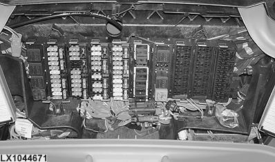
NOTE: As the changes were made during the ongoing the serial number break does not represent a clean changes have already been incorporated some tractors serial number 006999 and have not yet been incorporated some tractors from serial number 007000. The relevant tractors can identified the basis the fuse
LX1044671
serial number break 2008 (F02 F05 fuse arrangement)
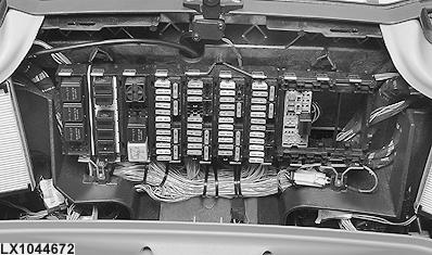
LX1044672
From serial number break 2008 (F04 F07 fuse arrangement)
Section Information
Group Information
Group References
Section T rouble Codes
Group A Control Unit
Group BCU Control Unit
Group BIF Control Unit
Group DSM Control Unit
Group DTI Control Unit
Group ECU Control Unit
Group EPC Control Unit
Group ETC Control Unit
Group JDL Control Unit
Group PLC Control Unit
Group SIC Control Unit
Group SSU Control Unit
Group TCU Control Unit
Group TEC Control Unit
Group TEI Control Unit
Group TSC Control Unit
Group UIC Control Unit
Group UIM Control Unit
Group VTI Control Unit
Section 212—Observable Symptoms
Group
Group Control Units
Group T ransmission
Group T ransmission
Group Systems
Group and Brakes
Group System
Group
Group ’ s Cab
Section 213—System Diagnostics
Group
Group T ransmission
Group System
Group JDL System Diagnostics
Group VTI (GreenStar) System Diagnostics
Section
Group Information
Group Checks
Group ests and Adjustments
Contents
Section
Air Intake and Cooling Systems
Group ests and Adjustments
Group 20A System
Group 20B Intake System
Group 20C System
Group 20D W eather Starting Aids
Section System
Group SE01 Motor and Charging Circuit
Group SE01A Preheater
Group SE01B Starting Aid
Group SE02 Control Unit (Basic Informator)
Group SE03
Group SE04 ’ s Seat and Cigarette Lighter
Group SE06
Group SE08 for Accessories
Group SE09 Dome Console Light and Access Step Lights
Group SE10 TC/ETC/HTC Control Units (Air Fan and Heater)
Group SE14 and 7 T erminal Power Outlet Sockets (SAE)
Group SE15 Control Unit (Electronic Hitch Control)
Group SE16 Control Unit (Basic Functions)
Group SE17 Socket and Service Socket
Group SE20 Control Unit (Suspension)
Group SE21 Control Unit (Selective Control V alves)
Group SE22 BUS T erminating Resistor
Group SE23A ECU Control Unit (Electronic Engine Control) for 4 V alve Engine with HPCR
Group SE23B ECU Control Unit (Electronic Engine Control) for 2 V alve Engine with HPCR
Group SE26 Control Unit ransmission Control with AutoPowr/IVT T ransmission)
Group SE26A Control Unit ransmission Control with PowrQuad Plus AutoQuad Plus T ransmission)
Group SE27 Control Unit ransmission Control with AutoPowr/IVT T ransmission)
Group SE28 Control Unit (Electronic Park Lock with AutoPowr/IVT T ransmission)
Group SE29 Rear V iew Mirrors
Group SE30 Control Unit (JDLink) Continued next page
Group SE32 Control Unit (ISOBUS)
Group SE33 (AMS)
Group SE35 Control Unit (AutoT rac)
Group SE36 Control Units (GreenStar Display)
Group SE37 Hydraulic Pick Hitch
Group SE39 Power Module (HF)
Group SE40 Power Module
Group SE41 Power Module
Group PC5 Power Module
Group PC6 Power Module (HF)
Group PLC Control Unit
Group SIC Control Unit
Group SSU Control Unit
Group TCU Control Unit
Group TEC Control Unit
Group TSC Control Unit
Group UIC Control Unit
Group SE42 Control Unit (CommandCenter)
Group 105A Information Connectors and Contacts
Group 105B Information Connectors (X001 X249)
Group 105C Information Connectors (X250 X499)
Group 105D Information Connectors (X500 X749)
Group 105E Information Connectors (X750 X999)
Group 105F Information Connectors (XGND)
Group 1 Information Wiring Harnesses
Group 1 Information Electrical Parts/Components
Group 1 15A Information Electrical Parts/Components (Actuators)
Group UIM Control Unit
Group VTI Control Unit
Section 253—AutoPowr/IVT T ransmission
Group Checks
Group ests and Adjustments
Group Operation
Section 255—PowrQuad T ransmission
Group Checks
Group ests and Adjustments
Group Operation
Section Systems
Group Checks
Group ests and Adjustments
Group 20A Wheel Drive Clutch
Group 20B ferential
Group 1 15B InformationElectrical Parts/Components (Sensors/Switches/Potentiometers)
Group 20C Drives
Group 20D O Options
Group 1 15C Information Electrical Parts/Components (Fuses/Relays/Diodes)
Group 1 15D
Section 260—Steering and Brakes
Group Checks
Information Electrical Parts/Components (Headlamps/Lights)
Group 1 15E Information Electrical Parts/Components (Other)
Group 120 Information Ground Connections
Group 125 Information CAN BUS Systems
Section 245—Electronic Control Units
Group and General Information Diagnostics
Group 10A T ests
Group 10B Calibrations
Group How Reprogram Control Units
Group BUS Systems
Group A Control Unit
Group BCU Control Unit
Group BIF Control Unit
Group DSM Control Unit
Group DTI Control Unit
Group ECU Control Unit
Group EPC Control Unit
Group ETC Control Unit
Group JDL Control Unit
Group PC0 Power Module
Group Checks
Group ests and Adjustments
Group 20A Steering
Group 20B V alve
Group 20C Brakes
Group 20G rac
Section System
Group Checks
Group ests and Adjustments
Group Operation
Group 20A Filter , Charge Pump and Hydraulic Pump
Group 20B
Group 20C Control V alves (SCVs)
Group 20D Control V alves (ICVs)
Group 20E Block
Section
Group Checks
Group ests and Adjustments
Group Operation
Section ’ s Cab
Group Checks
Group ests and Adjustments Continued next page
Group 20A entilation/Heating
Group 20B Conditioning System
Group 20C rak
Group 20D Suspension
Section 299—Special T ools
Group T ools (Dealer Fabricated)
Group T ools vailable Spare Parts)
Thanks very much for your reading,
Want to get more information,
Please click here, Then get the complete manual
NOTE:
If there is no response to click on the link above, please download the PDF document first, and then click on it.