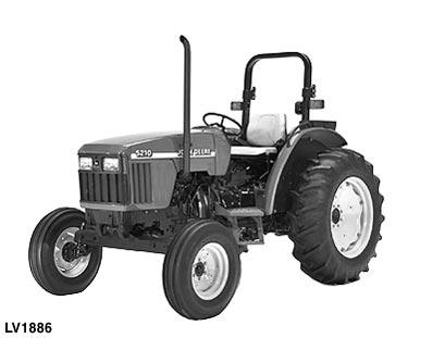
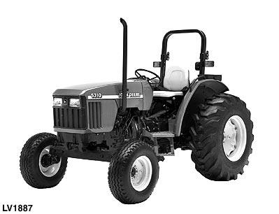
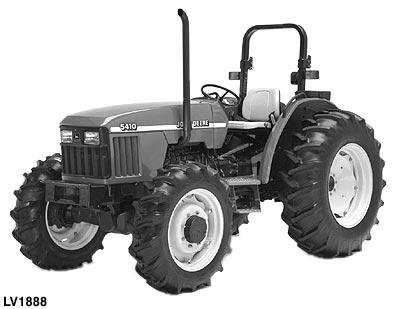
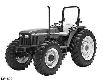
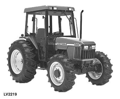
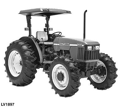
5210, 5310 5410 and 5510 Tractors
For complete service information also see:
Component Technical Manuals
3029 2.9 L Engine. .
4045 4.5 L Engine.
Alternators and Starting Motors.
CTM125
CTM104
CTM77
FOREWORD
This manual is written for an experienced technician. Essential tools required in performing certain service work are identified in this manual and are recommended for use.
Live with safety: Read the safety messages in the introduction of this manual and the cautions presented throughout the text of the manual.
NThis is the safety-alert symbol. When you see this symbol on the machine or in this manual, be alert to the potential for personal injury.
Technical manuals are divided in two parts: repair and diagnostics. Repair sections tell how to repair the components. Diagnostic sections help you identify the majority of routine failures quickly.
Information is organized in groups for the various components requiring service instruction. At the beginning of each group are summary listings of all applicable essential tools, other materials needed to do the job and service parts kits.
Section 10, Group 10—General Specifications, consists of all applicable specifications, near tolerances and specific torque values for various components on each individual machine.
Binders, binder labels, and tab sets can be ordered by John Deere dealers direct from the John Deere Distribution Service Center.
This manual is part of a total product support program.
FOS MANUALS—REFERENCE
TECHNICAL MANUALS—MACHINE SERVICE
COMPONENT TECHNICAL MANUALS—COMPONENT SERVICE
Fundamentals of Service (FOS) Manuals cover basic theory of operation, fundamentals of troubleshooting, general maintenance, and basic types of failures and their causes. FOS Manuals are for training new personnel and for reference by experienced technicians.
Technical Manuals are concise guides for specific machines. Technical manuals are on-the-job guides containing only the vital information needed for diagnosis, analysis, testing, and repair.
Component Technical Manuals are concise service guides for specific components. Component technical manuals are written as stand-alone manuals covering multiple machine applications.
SECTION 10—GENERAL INFORMATION
Group 05—Safety
Group 10—General Specifications
Group 20—Fuel and Lubricants
Group 25—Serial Number Locations
Group 30—Features and Accessories
SECTION 20—ENGINE REPAIR
Group 05—Engine
Group 10—Cooling System
SECTION 30—FUEL AND AIR REPAIR
Group 05—Fuel System
Group 10—Air Intake System
Group 15—Speed Control Linkage
SECTION 40—ELECTRICAL REPAIR
Group 05—Battery, Starter and Alternator
Group 10—Electrical System Components
Group 15—Wiring Harness
SECTION 50—POWER TRAIN REPAIR
Group 05—Clutch Housing
Group 10—Clutch
Assembly—CollarShift/SyncShuttle™ Transmissions
Group 11—Clutch Assembly—PowrReverser™ Transmission
Group 12—PowrReverser™
Group 15—CollarShift/SyncShuttle™ Transmission
Group 16—PowrReverser™ Transmission
Group 20—Rear PTO Drive Shaft
Group 25—Differential
Group 30—Final Drives
Group 35—Mechanical Front Wheel Drive
Group 40—Creeper Assembly
SECTION 60—STEERING AND BRAKE REPAIR
Group 05—Steering Repair
Group 10—Brake Repair
SECTION 70—HYDRAULIC REPAIR
Group 05—Hydraulic Pump and Filter
Group 06—Hydraulic Oil Cooler
Group 10—Rockshaft
Group 15—Dual Selective Control Valve
Group 16—Single (Third) Selective Control Valve
Group 20—Hydraulic Mid Mount Coupler
Group 25—Hydraulic Power Beyond
SECTION 80—MISCELLANEOUS REPAIR
Group 05—Front Axle—2WD
Group 10—Wheels
Group 15—3-Point Hitch
SECTION 90—OPERATOR STATION REPAIR
Group 05—Seat and Support
Group 06—Control Console and Panel—Tractors Without Cab
Group 10—ROLL-GARD®
Group 15—Cab Components
Group 20—Air Conditioning System
Group 25—Heating System
SECTION 210—TEST AND ADJUSTMENT SPECIFICATIONS/OPERATIONAL CHECKOUT PROCEDURES
Group 05—Test and Adjustment Specifications
Group 10—Operational Checkout Procedures
SECTION 220—ENGINE OPERATION, TESTS AND ADJUSTMENTS
Group 05—Component Location
Group 10—Theory of Operation
Group 15—Diagnosis, Tests and Adjustments
SECTION 230—FUEL/AIR OPERATION, TESTS AND ADJUSTMENTS
Group 05—Component Location
Group 10—Theory of Operation
Group 15—Diagnosis, Tests and Adjustments
SECTION 240—ELECTRICAL SYSTEM OPERATION, TESTS AND ADJUSTMENTS
Group 05—Component Location
Group 10—Theory of Operation
Group 15—Diagnosis, Tests and Adjustments
Continued on next page
information, illustrations and specifications in this manual are based on the latest information available at the time of
Group 20—Wiring Schematics
SECTION 250—POWER TRAIN OPERATION, TESTS AND ADJUSTMENTS
Group 05—Component Location—Collar Shift/SyncShuttle™ Transmission
Group 06—Component Location—PowrReverser™ Transmission
Group 10—Theory of Operation—Collar Shift/SyncShuttle™ Transmission
Group 11—Theory of Operation—PowrReverser™ Transmission
Group 15—Diagnosis, Tests and Adjustments—CS/SS Transmission
Group 16—Diagnosis, Tests and Adjustments—PowrReverser™
SECTION 260—STEERING AND BRAKE OPERATION, TESTS AND ADJUSTMENTS
Group 05—Component Location Group 10—Theory of Operation
Group 15—Diagnosis, Tests and Adjustments
SECTION 270—HYDRAULIC SYSTEM OPERATION, TESTS AND ADJUSTMENTS
Group 05—Component Location
Group 10—Theory of Operation
Group 15—Diagnosis
Group 16—Hydraulic Tests—Without SCV
Group 17—Hydraulic Tests—With SCV
Group 18—Hydraulic Tests—All Group 19—Adjustments
Group 20—Hydraulic Schematics
SECTION 290—OPERATOR STATION
Group 05—Component Location Group 10—Theory of Operation
Group 15—Diagnosis, Tests and Adjustments
SECTION 299—DEALER FABRICATED TOOLS
Group 00—Dealer Fabricated Tools
Index
Group 05—Safety
Group 10—General Specifications
10-05-1
Machine Specifications 5210 and 5310 . . 10-10-1
Machine Specifications 5410 and 5510 . . 10-10-6
Repair Specifications
Service Recommendations
For O-Ring Boss Fittings .
For Flat Face O-Ring Seal Fittings .
Metric Cap Screw Torque Values—Grade
7
Metric Series Torque Chart
Inch Series Torque Chart .
Abbreviations
Group 20—Fuel and Lubricants
Diesel Fuel Specifications
Fuel Storage
Do Not Use Galvanized Containers
Fill Fuel Tank
Engine Coolant
Liquid Coolant Conditioner
MFWD Gear Oil
Grease
Group 25—Serial Number Locations
10-10-11
10-10-19
. 10-10-20
10-10-21
10-10-22
. 10-10-23
10-10-24
10-20-1
10-20-1
10-20-2
10-20-2
10-20-4
10-20-4
10-20-6
10-20-6
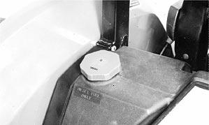
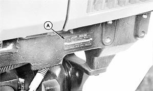
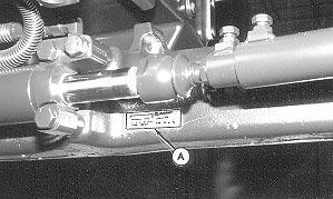
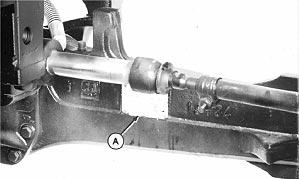
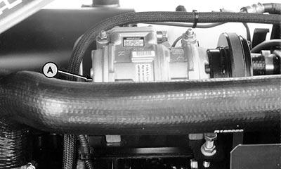
Product Identification Number Location . . 10-25-1
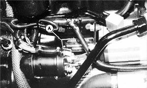
Serial Number Location Engine
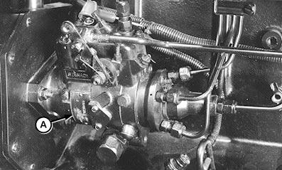
Fuel Injection Pump
Group 30—Features and Accessories Features and Accessories
Standard Features—5210 and 5310 .
Standard Features—5410 and 5510
Standard Features—5210 through 5510 .
10-25-1
10-25-1
Factory Installed Optional Equipment (5210—5510) .
Field Installed Optional Kits and Accessories—5210 through 5510 . .
10-30-1
10-30-2
10-30-4
RECOGNIZE SAFETY INFORMATION
This is the safety-alert symbol. When you see this symbol on your machine or in this manual, be alert to the potential for personal injury.
Follow recommended precautions and safe operating practices.
UNDERSTAND SIGNAL WORDS
A signal word—DANGER, WARNING, or CAUTION—is used with the safety-alert symbol. DANGER identifies the most serious hazards.
DANGER or WARNING safety signs are located near specific hazards. General precautions are listed on CAUTION safety signs. CAUTION also calls attention to safety messages in this manual.
FOLLOW SAFETY INSTRUCTIONS
Carefully read all safety messages in this manual and on your machine safety signs. Keep safety signs in good condition. Replace missing or damaged safety signs. Be sure new equipment components and repair parts include the current safety signs. Replacement safety signs are available from your John Deere dealer.
Learn how to operate the machine and how to use controls properly. Do not let anyone operate without instruction.
Keep your machine in proper working condition. Unauthorized modifications to the machine may impair the function and/or safety and affect machine life.
If you do not understand any part of this manual and need assistance, contact your John Deere dealer.
HANDLE FLUIDS SAFELY—AVOID FIRES
When you work around fuel, do not smoke or work near heaters or other fire hazards.
Store flammable fluids away from fire hazards. Do not incinerate or puncture pressurized containers.
Make sure machine is clean of trash, grease, and debris.
Do not store oily rags; they can ignite and burn spontaneously.
PREVENT BATTERY EXPLOSIONS
Keep sparks, lighted matches, and open flame away from the top of battery. Battery gas can explode.
Never check battery charge by placing a metal object across the posts. Use a volt-meter or hydrometer.
Do not charge a frozen battery; it may explode. Warm battery to 16˚C (60˚F).
PREPARE FOR EMERGENCIES
Be prepared if a fire starts.
Keep a first aid kit and fire extinguisher handy.
Keep emergency numbers for doctors, ambulance service, hospital, and fire department near your telephone.
PREVENT ACID BURNS
Sulfuric acid in battery electrolyte is poisonous. It is strong enough to burn skin, eat holes in clothing, and cause blindness if splashed into eyes.
Avoid the hazard by:
1. Filling batteries in a well-ventilated area.
2. Wearing eye protection and rubber gloves.
3. Avoiding breathing fumes when electrolyte is added.
4. Avoiding spilling or dripping electrolyte.
5. Use proper jump start procedure.
If you spill acid on yourself:
1. Flush your skin with water.
2. Apply baking soda or lime to help neutralize the acid.
3. Flush your eyes with water for 15—30 minutes. Get medical attention immediately.
If acid is swallowed:
1. Do not induce vomiting.
2. Drink large amounts of water or milk, but do not exceed 2 L (2 quarts).
3. Get medical attention immediately.
SERVICE COOLING SYSTEM SAFELY
Explosive release of fluids from pressurized cooling system can cause serious burns.
Shut off engine. Only remove filler cap when cool enough to touch with bare hands. Slowly loosen cap to first stop to relieve pressure before removing completely.
HANDLE CHEMICAL PRODUCTS SAFELY
Direct exposure to hazardous chemicals can cause serious injury. Potentially hazardous chemicals used with John Deere equipment include such items as lubricants, coolants, paints, and adhesives.
A Material Safety Data Sheet (MSDS) provides specific details on chemical products: physical and health hazards, safety procedures, and emergency response techniques.
Check the MSDS before you start any job using a hazardous chemical. That way you will know exactly what the risks are and how to do the job safely. Then follow procedures and recommended equipment.
(See your John Deere dealer for MSDS’s on chemical products used with John Deere equipment.)
AVOID HIGH-PRESSURE FLUIDS
Escaping fluid under pressure can penetrate the skin causing serious injury.
Avoid the hazard by relieving pressure before disconnecting hydraulic or other lines. Tighten all connections before applying pressure.
Search for leaks with a piece of cardboard. Protect hands and body from high pressure fluids.
If an accident occurs, see a doctor immediately. Any fluid injected into the skin must be surgically removed within a few hours or gangrene may result. Doctors unfamiliar with this type of injury should reference a knowledgeable medical source. Such information is available from Deere & Company Medical Department in Moline, Illinois, U.S.A.
PARK MACHINE SAFELY
Before working on the machine:
• Lower all equipment to the ground.
• Shift transmission to PARK.
• Engage park brake if equipped.
• Stop the engine and remove the key.
• Disconnect the battery ground strap.
• Hang a “DO NOT OPERATE” tag in operator station.
SUPPORT MACHINE PROPERLY
Always lower the attachment or implement to the ground before you work on the machine. If you must work on a lifted machine or attachment, securely support the machine or attachment.
Do not support the machine on cinder blocks, hollow tiles, or props that may crumble under continuous load. Do not work under a machine that is supported solely by a jack. Follow recommended procedures in this manual.
WEAR PROTECTIVE CLOTHING
Wear close fitting clothing and safety equipment appropriate to the job.
Prolonged exposure to loud noise can cause impairment or loss of hearing.
Wear a suitable hearing protective device such as earmuffs or earplugs to protect against objectionable or uncomfortable loud noises.
Operating equipment safely requires the full attention of the operator. Do not wear radio or music headphones while operating machine.
WORK IN CLEAN AREA
Before starting a job:
• Clean work area and machine.
• Make sure you have all necessary tools to do your job.
• Have the right parts on hand.
• Read all instructions thoroughly; do not attempt shortcuts.
SERVICE MACHINES SAFELY
Tie long hair behind your head. Do not wear a necktie, scarf, loose clothing, or necklace when you work near machine tools or moving parts. If these items were to get caught, severe injury could result.
Remove rings and other jewelry to prevent electrical shorts and entanglement in moving parts.
WORK IN VENTILATED AREA
Engine exhaust fumes can cause sickness or death. If it is necessary to run an engine in an enclosed area, remove the exhaust fumes from the area with an exhaust pipe extension.
If you do not have an exhaust pipe extension, open the doors and get outside air into the area.
ILLUMINATE WORK AREA SAFELY
Illuminate your work area adequately but safely. Use a portable safety light for working inside or under the machine. Make sure the bulb is enclosed by a wire cage. The hot filament of an accidentally broken bulb can ignite spilled fuel or oil.
REPLACE SAFETY SIGNS
Replace missing or damaged safety signs. See the machine operator’s manual for correct safety sign placement.
USE PROPER LIFTING EQUIPMENT
Lifting heavy components incorrectly can cause severe injury or machine damage.
Follow recommended procedure for removal and installation of components in the manual.
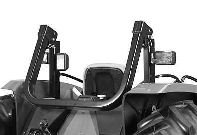
KEEP ROPS INSTALLED PROPERLY
Make certain all parts are reinstalled correctly if the roll-over protective structure (ROPS) is loosened or removed for any reason. Tighten mounting bolts to proper torque.
The protection offered by ROPS will be impaired if ROPS is subjected to structural damage, is involved in an overturn incident, or is in any way altered by welding, bending, drilling, or cutting. A damaged ROPS should be replaced, not reused.
SERVICE TIRES SAFELY
Explosive separation of a tire and rim parts can cause serious injury or death.
Do not attempt to mount a tire unless you have the proper equipment and experience to perform the job.
Always maintain the correct tire pressure. Do not inflate the tires above the recommended pressure. Never weld or heat a wheel and tire assembly. The heat can cause an increase in air pressure resulting in a tire explosion. Welding can structurally weaken or deform the wheel.
When inflating tires, use a clip-on chuck and extension hose long enough to allow you to stand to one side and NOT in front of or over the tire assembly. Use a safety cage if available.
Check wheels for low pressure, cuts, bubbles, damaged rims or missing lug bolts and nuts.
AVOID HARMFUL ASBESTOS DUST
Avoid breathing dust that may be generated when handling components containing asbestos fibers. Inhaled asbestos fibers may cause lung cancer.
Components in products that may contain asbestos fibers are brake pads, brake band and lining assemblies, clutch plates, and some gaskets. The asbestos used in these components is usually found in a resin or sealed in some way. Normal handling is not hazardous as long as airborne dust containing asbestos is not generated.
Avoid creating dust. Never use compressed air for cleaning. Avoid brushing or grinding material containing asbestos. When servicing, wear an approved respirator. A special vacuum cleaner is recommended to clean asbestos. If not available, apply a mist of oil or water on the material containing asbestos.
Keep bystanders away from the area.
AVOID HEATING NEAR PRESSURIZED FLUID LINES
Flammable spray can be generated by heating near pressurized fluid lines, resulting in severe burns to yourself and bystanders. Do not heat by welding, soldering, or using a torch near pressurized fluid lines or other flammable materials. Pressurized lines can be accidentally cut when heat goes beyond the immediate flame area.
REMOVE PAINT BEFORE WELDING OR HEATING
Avoid potentially toxic fumes and dust.
Hazardous fumes can be generated when paint is heated by welding, soldering, or using a torch.
Do all work outside or in a well ventilated area. Dispose of paint and solvent properly.
Remove paint before welding or heating:
• If you sand or grind paint, avoid breathing the dust. Wear an approved respirator.
• If you use solvent or paint stripper, remove stripper with soap and water before welding. Remove solvent or paint stripper containers and other flammable material from area. Allow fumes to disperse at least 15 minutes before welding or heating.
USE PROPER TOOLS
Use tools appropriate to the work. Makeshift tools and procedures can create safety hazards.
Use power tools only to loosen threaded parts and fasteners.
For loosening and tightening hardware, use the correct size tools. DO NOT use U.S. measurement tools on metric fasteners. Avoid bodily injury caused by slipping wrenches.
Use only service parts meeting John Deere specifications.
DISPOSE OF WASTE PROPERLY
Improperly disposing of waste can threaten the environment and ecology. Potentially harmful waste used with John Deere equipment include such items as oil, fuel, coolant, brake fluid, filters, and batteries.
Use leakproof containers when draining fluids. Do not use food or beverage containers that may mislead someone into drinking from them.
Do not pour waste onto the ground, down a drain, or into any water source.
Air conditioning refrigerants escaping into the air can damage the Earth’s atmosphere. Government regulations may require a certified air conditioning service center to recover and recycle used air conditioning refrigerants.
Inquire on the proper way to recycle or dispose of waste from your local environmental or recycling center, or from your John Deere dealer.
LIVE WITH SAFETY
Before returning machine to customer, make sure machine is functioning properly, especially the safety systems. Install all guards and shields.
MACHINE SPECIFICATIONS 5210 AND 5310
52105310
ENGINE
MakeJohn DeereJohn Deere
TypeDieselDiesel
ModelCD3029DLV50CD3029TLV50
AspirationNaturalTurbocharged
Horsepower39 kW (53 hp)47 kW (63 hp)
Rated Engine Speed2400 rpm2400 rpm
Operating Range1600—2400 rpm1600—2400 rpm
Number of Cylinders33
Displacement2.9 L2.9 L (179 cu in.)(179 cu in.)
Bore and Stroke106 x 110 mm106 x 110 mm (4.19 x 4.33 in.)(4.19 x 4.33 in.)
Compression Ratio17.8:117.8:1
Fast Idle2600 rpm2600 rpm
Slow Idle800 rpm800 rpm
Start AidAir HeaterAir Heater
Firing Order1-2-31-2-3
Timing18˚ BTDC18˚ BTDC
LubricationPressurizedPressurized
CoolingLiquid CooledLiquid Cooled Air CleanerDry Type w/Safety ElementDry Type w/Safety Element Engine ShutoffKey SwitchKey Switch
FUEL SYSTEM
TypeDirect InjectionDirect Injection Injection Pump TypeRotary w/ElectricRotary w/Electric ShutoffShutoff
ELECTRICAL SYSTEM
Type12 Volt12 Volt
Battery Size700 Cold Cranking Amps700 Cold Cranking Amps at -18˚Cat -18˚C
Alternator40 Amp Without Cab40 Amp Without Cab 60 Amp With Cab60 Amp With Cab
Specifications/Machine Specifications 5210 and 5310
52105310
DRIVE TRAIN
Transmission Type StandardCollarShiftCollarShift OptionalSyncShuttle™SyncShuttle™ Number of Speeds9 Forward, 3 Reverse9 Forward, 3 Reverse OptionalPowrReverser™PowrReverser™ Number of Speeds12 Forward, 12 Reverse12 Forward, 12 Reverse
Final DrivePlanetaryPlanetary ClutchDual, DryDual, Dry PowrReverser™Multi-Disk, WetMulti-Disk, Wet
STEERING/BRAKES
SteeringHydrostatic PowerHydrostatic Power BrakesWet DiskWet Disk Self-EqualizingSelf-Equalizing
HYDRAULIC SYSTEM
TypeOpen CenterOpen Center
Working Pressure18995—19685 kPa18995—19685 kPa (190—197 bar)(190—197 bar) (2755—2855 psi)(2755—2855 psi)
Pump TypeTandem GearTandem Gear
Capacity68.8 L/min (18.2 gpm)68.8 L/min (18.2 gpm)
Hitch Lift Capacity at 610 mm (24 in.)
Behind Hitch Balls1530 kg (3374 lb)1530 kg (3374 lb)
Lift Control TypePosition and DepthPosition and Depth
REAR PTO
TypeFully IndependentFully Independent Horsepower (Standard Mode)34 kW (45 hp)41 kW (55 hp) Speed
540 (Standard Mode) @ 2400 rpm Engine Speed540 rpm540 rpm
540E (Economy Mode)* @ 1700 rpm Engine Speed540 rpm540 rpm
CAPACITIES
Fuel Tank (Open Station)68 L (18 U.S. gal)68 L (18 U.S. gal)
Tank (Cab Tractors)83
Crankcase
*Available only on SyncShuttle™ Transmission. LV,17161010,A2 -19-02MAR98
(18JUN99)
52105310
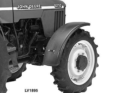
TIRES
(Standard Equipment)
2WD
Front6.50—16 6PR F27.50—16 6PR F2
Rear13.6—28 4PR R114.9—28 4PR R1
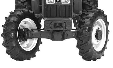
MFWD
Front8.3—24 4PR R19.5—24 4PR R1
Rear13.6—28 4PR R114.9—28 6PR R1
OVERALL DIMENSIONS
(Standard Equipment)
Ground Clearance
Drawbar364 mm (14.3 in.)364 mm (14.3 in.)
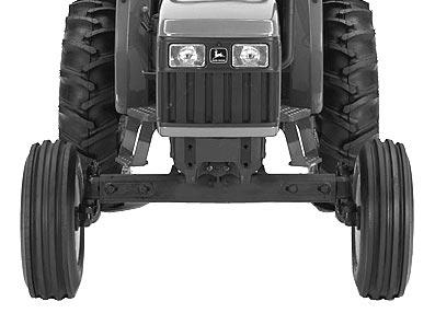
Front Axle
2WD478 mm (19 in.)478 mm (19 in.)
MFWD430 mm (17 in.)430 mm (17 in.)
Overall Length without Hitch and Drawbar3150 mm (124 in.)3150 mm (124 in.)
Overall Width (Maximum)2402 mm (94.6 in.)2402 mm (94.6 in.)
Height To Top of Steering Wheel1600 mm (63 in.)1625 mm (64 in.)
To Top of ROPS*
Extended2254 mm (88.7 in.)2254 mm (88.7 in.)
Folded1948 mm (76.7 in.)1973 mm (77.7 in.)
To Top of Cab from Center Line of Rear Axle1844 mm (72.6 in.)1844 mm (72.6 in.)
Approximate Weight**
2WD***1982 kg (4370 lb)2064 kg (4550 lb)
MFWD***2145 kg (4730 lb)2250 kg (4960 lb)
*Add 4 inches to top of ROPS if equipped with a canopy.
**Weights will vary slightly with optional tires.
***Add 1000 lbs. to weight of tractor if equipped with cab.
(Specifications and design subject to change without notice.)
Travel Speeds for CollarShift or SyncShuttle™ Units at Full Engine RPM with Rear Tire Types*14.9—28 R114.9—28 R1
Forward Gears
C-1 Gear**0.3 km/h (0.2 mph)0.3 km/h (0.2 mph)
C-2 Gear**0.5 km/h (0.3 mph)0.5 km/h (0.3 mph)
C-3 Gear**0.7 km/h (0.4 mph)0.7 km/h (0.4 mph)
A-1st Gear2.0 km/h (1.2 mph)2.0 km/h (1.2 mph)
A-2nd Gear2.1 km/h (1.3 mph)2.1 km/h (1.3 mph)
A-3rd Gear4.0 km/h (2.5 mph)4.0 km/h (2.5 mph)
B-1st Gear4.7 km/h (2.9 mph)4.7 km/h (2.9 mph)
B-2nd Gear6.7 km/h (4.2 mph)6.7 km/h (4.2 mph)
B-3rd Gear9.2 km/h (5.7 mph)9.2 km/h (5.7 mph)
C-1st Gear12.8 km/h (7.9 mph)12.8 km/h (7.9 mph)
C-2nd Gear18.4 km/h (11.5 mph)18.4 km/h (11.5 mph)
C-3rd Gear25.1 km/h (15.6 mph)25.1 km/h (15.6 mph)
Reverse Gears
C-R Gear**0.6 km/h (0.34 mph)0.6 km/h (0.34 mph)
R-1st Gear3.4 km/h (2.1 mph)3.4 km/h (2.1 mph)
R-2nd Gear7.8 km/h (4.8 mph)7.8 km/h (4.8 mph)
R-3rd Gear21.3 km/h (13.2 mph)21.3 km/h (13.2 mph)
*Travel speeds will vary with optional rear tires.
**Speeds of tractors equipped with optional creeper assembly. LV,17161010,A4 -19-02MAR98
General Specifications/Machine Specifications 5210 and 5310
Travel Speeds for PowrReverser™ Units at Full Engine RPM with Rear Tire Types*16.9—30
(3.37) 6.26 (3.89)5.42 (3.37) 6.26 (3.89) B-37.00 (4.34) 8.10 (5.04)7.00 (4.34) 8.10 (5.04) B-49.56 (5.94) 11.0 (6.87)9.56 (5.94) 11.0 (6.87)
*Travel speeds will vary with optional rear tires.
**Speeds of tractors equipped with optional creeper assembly. LV,17161010,A5 -19-02MAR98
MACHINE SPECIFICATIONS 5410 AND 5510
ENGINE
MakeJohn DeereJohn Deere TypeDieselDiesel
ModelCD4045DLV50CD4045TLV50
AspirationNaturalTurbocharged
Horsepower56 kW (75 hp)63 kW (85 hp)
Rated Engine Speed2400 rpm2400 rpm
Operating Range1600—2400 rpm1600—2400 rpm
Number of Cylinders44
Displacement4.5 L4.5 L (274 cu in.)(274 cu in.)
Bore and Stroke106 x 127 mm106 x 127 mm (4.19 x 5.00 in.)(4.19 x 5.00 in.)
Compression Ratio17.6:117.0:1
Fast Idle2600 rpm2600 rpm
Slow Idle800 rpm800 rpm
Start AidAir HeaterAir Heater
Firing Order1-3-4-21-3-4-2
Timing17˚ BTDC17˚ BTDC
LubricationPressurizedPressurized
CoolingLiquid CooledLiquid Cooled Air CleanerDry Type w/Safety ElementDry Type w/Safety Element Engine ShutoffKey SwitchKey Switch
FUEL SYSTEM
TypeDirect InjectionDirect injection
Injection Pump TypeRotary w/ElectricRotary w/Electric ShutoffShutoff
ELECTRICAL SYSTEM
Type12 Volt12 Volt
Battery Size700 Cold Cranking Amps700 Cold Cranking Amps at -18˚Cat -18˚C
Alternator40 Amp Without Cab40 Amp Without Cab 65 Amp With Cab65 Amp With Cab
54105510
DRIVE TRAIN
Transmission Type StandardCollarShiftCollarShift OptionalSyncShuttle™SyncShuttle™ Number of Speeds9 Forward, 3 Reverse9 Forward, 3 Reverse OptionalPowrReverser™PowrReverser™ Number of Speeds12 Forward, 12 Reverse12 Forward, 12 Reverse
Final DrivePlanetaryPlanetary ClutchDual, DryDual, Dry PowrReverser™Multi-Disk, WetMulti-Disk, Wet
STEERING/BRAKES
SteeringHydrostatic PowerHydrostatic Power BrakesWet DiskWet Disk Self-EqualizingSelf-Equalizing
HYDRAULIC SYSTEM
TypeOpen CenterOpen Center
Working Pressure18995—19685 kPa18995—19685 kPa (190—197 bar)(190—197 bar) (2755—2855 psi)(2755—2855 psi)
Pump TypeTandem GearTandem Gear Capacity85 L/min (22.5 gpm)85 L/min (22.5 gpm)
Hitch Lift Capacity at 610 mm (24 in.)
Behind Hitch Balls1530 kg (3374 lb)1530 kg (3374 lb) Lift Control TypePosition and DepthPosition and Depth
REAR PTO
TypeFully IndependentFully Independent Horsepower48 kW (65 hp)56 kW (75 hp)
Speed
540 (Standard Mode) @ 2400 rpm Engine Speed540 rpm540 rpm 540E (Economy Mode)* @ 1700 rpm Engine Speed540 rpm540 rpm
CAPACITIES
Fuel Tank (Open Station)68 L (18 U.S. gal)83 L (22 U.S. gal)
Fuel Tank (Cab Tractors)83
Cooling System10.8
Engine Crankcase w/Filter8.5
*Available only on SyncShuttle™ Transmission. LV,17161010,A7 -19-02MAR98
54105510
TIRES
(Standard Equipment)
2WD
Front7.50—16 6PR F27.50—16 6PR F2
Rear16.9—30 6PR R116.9—30 6PR R1
MFWD
Front11.2—24 4PR R111.2—24 4PR R1
Rear16.9—30 6PR R116.9—30 6PR R1
OVERALL DIMENSIONS
(Standard Equipment)
Ground Clearance
Drawbar
2WD497.8 mm (19.6 in.)497.8 mm (19.6 in.)
MFWD477.5 mm (18.8 in.)477.5 mm (18.8 in.)
Front Axle
2WD464.8 mm (18.3 in.)464.8 mm (18.3 in.)
MFWD391.1 mm (15.4 in.)391.1 mm (15.4 in.)
Overall Length without Hitch, Drawbar and Weights
2WD3197.8 mm (125.9 in.)3510.2 mm (138.2 in.)
MFWD3309.6 mm (130.3 in.)3510.2 mm (138.2 in.)
Overall Width (Maximum)
2WD1744.9 mm (68.7 in.)1744.9 mm (68.7 in.)
MFWD1744.9 mm (68.7 in.)1744.9 mm (68.7 in.)
Height
To Top of Steering
Wheel1661 mm (65.4 in.)1696.7 mm (66.8 in.)
To Top of ROPS*
Extended2316.4 mm (91.2 in.)2481.5 mm (97.7 in.)
Folded1981 mm (78 in.)2024.3 mm (79.7 in.)
To Top of Cab from Center Line of Rear Axle1844 mm (72.6 in.)1844 mm (72.6 in.)
Approximate Weight**
2WD***2390 kg (5270 lb)2599 kg (5730 lb)
MFWD***2581 kg (5690 lb)2785.1 kg (6140 lb)
*Add 4 inches to top of ROPS if equipped with a canopy.
**Weights will vary slightly with optional tires.
***Add 1000 lbs. to weight of tractor if equipped with cab.
(Specifications and design subject to change without notice.)
-19-02MAR98
Specifications/Machine Specifications 5410 and 5510
Travel Speeds for CollarShift or SyncShuttle™ Units at Full Engine RPM with Rear Tire Types*14.9—28 R116.9—30 R1
Forward Gears
C-1 Gear**0.3 km/h (0.2 mph)13.7 km/h (8.5 mph)
C-2 Gear**0.5 km/h (0.3 mph)19.8 km/h (12.3 mph)
C-3 Gear**0.7 km/h (0.4 mph)27.0 km/h (16.7 mph)
A-1st Gear2.0 km/h (1.2 mph)2.1 km/h (1.3 mph)
A-2nd Gear2.1 km/h (1.3 mph)3.1 km/h (1.9 mph)
A-3rd Gear4.0 km/h (2.5 mph)4.2 km/h (2.6 mph)
B-1th Gear4.7 km/h (2.9 mph)4.9 km/h (3.1 mph)
B-2nd Gear6.7 km/h (4.2 mph)7.2 km/h (4.4 mph)
B-3rd Gear9.2 km/h (5.7 mph)9.8 km/h (6.1 mph)
C-1st Gear12.8 km/h (7.9 mph)13.7 km/h (8.5 mph)
C-2nd Gear18.4 km/h (11.5 mph)19.8 km/h (12.3 mph)
C-3rd Gear25.1 km/h (15.6 mph)27.0 km/h (16.7 mph)
Reverse Gears
C-R Gear**0.6 km/h (0.34 mph)0.59 km/h (0.37 mph)
R-1st Gear3.4 km/h (2.1 mph)0.35 km/h (0.25 mph)
R-2nd Gear7.8 km/h (4.8 mph)0.51 km/h (0.32 mph)
R-3rd Gear21.3 km/h (13.2 mph)0.70 km/h (0.43 mph)
*Travel speeds will vary with optional rear tires.
**Speeds of tractors equipped with optional creeper assembly. LV,17161010,A9 -19-02MAR98
General Specifications/Machine Specifications 5410 and 5510
Travel Speeds for PowrReverser™ Units at Full Engine RPM with Rear Tire Types*16.9—30
(3.37) 6.26 (3.89)5.42 (3.37) 6.26 (3.89) B-37.00 (4.34) 8.10 (5.04)7.00 (4.34) 8.10 (5.04) B-49.56 (5.94) 11.0 (6.87)9.56 (5.94) 11.0 (6.87)
(12.3) 22.9 (14.2)19.8 (12.3) 22.9 (14.2)
*Travel speeds will vary with optional rear tires.
**Speeds of tractors equipped with optional creeper assembly. LV,17161010,A10-19-02MAR98
REPAIR SPECIFICATIONS
ItemMeasurementSpecification
SECTION 20—ENGINE REPAIR
For all repair specifications use CTM125 for 2.9 L engines or CTM104 for 4.5 L engines
Engine-to-Clutch Housing Cap ScrewTorque318 N·m (235 lb-ft)
Engine-to-Front Support Cap Screw and/or NutTorque318 N·m (235 lb-ft)
Engine-to-Front Support (Dowel Hole) Cap ScrewTorque176 N·m (130 lb-ft)
Top of Dipstick Tube to Oil Pan RailDistance156 mm (6.150 in.)
SECTION 30—FUEL AND AIR REPAIR
For all fuel injection nozzle and turbocharger repair use CTM125 for 2.9 L engines or CTM104 for 4.5 L engines
Fuel Tank Retaining Straps L-BoltTorque35 N·m (26 lb-ft)
Turbocharger
Oil Drain LineTorque80 N·m (59 lb-ft)
Oil Inlet LineTorque27 N·m (20 lb-ft)
Mounting NutsTorque47 N·m (35 lb-ft)
SECTION 40—ELECTRICAL SYSTEM
For starter repair—Use CTM77
SECTION 50—POWER TRAIN REPAIR
3—Cylinder Engine-to-Clutch Housing Cap Screws and NutsTorque300 N·m (225 lb-ft)
4—Cylinder Engine-to-Clutch Housing Cap Screws and NutsTorque350 N·m (255 lb-ft)
Clutch (CollarShift and SyncShuttle™ Transmissions)
Clutch-to-Flywheel Cap ScrewTorque36 N·m (27 lb-ft)
Traction Clutch DiscMinimum Thickness6.50 mm (0.260 in.)
PTO Clutch DiscMinimum Thickness5.50 mm (0.220 in.)
PTO Clutch Rear Pressure PlateMinimum Thickness18.80 mm (0.740 in.)
PTO Clutch Front Pressure PlateMinimum Thickness17.30 mm (0.680 in.)
Traction Clutch Front Pressure PlateMinimum Thickness30.00 mm (1.181 in.)
Continued on next page. LV,17161015,A1 -19-02MAR98 General Specifications/Repair Specifications
(18JUN99)
SECTION 50—POWER TRAIN REPAIR—CONTINUED
Clutch (CollarShift and SyncShuttle™ transmissions)
Traction Clutch Rear Pressure PlateMinimum Thickness17.00 mm (0.669 in.)
Yoke-to-Armshaft Cap ScrewTorque65 N·m (48 lb-ft)
Clutch (PowrReverser™ Transmissions)
Clutch-to-Flywheel Cap ScrewTorque36 N·m (27 lb-ft)
PTO Clutch DiscMinimum Thickness5.50 mm (0.220 in.)
PTO Clutch Front Pressure PlateMinimum Thickness18.80 mm (0.740 in.)
PTO Clutch Rear Pressure PlateMinimum Thickness17.30 mm (0.680 in.)
PTO Clutch Sleeve Guide-to-Clutch Housing Cap ScrewTorque26 N·m (20 lb-ft)
PTO Clutch Yoke Cap ScrewTorque65 N·m (48 lb-ft)
PowrReverser™
Transmission Pump-to-Clutch Housing Cap ScrewTorque26 N·m (20 lb-ft)
Rear Bearing Support Plate-to-Clutch Housing Cap ScrewTorque26 N·m (20 lb-ft)
Forward/Reverse Clutch DiscMinimum Thickness2.70 mm (0.106 in.)
Forward/Reverse Clutch Inner PlateMinimum Thickness3.85 mm (0.151 in.)
Forward/Reverse Clutch Outer PlateMinimum Thickness5.85 mm (0.230 in.)
Forward/Reverse Clutch SpringsMinimum Length58 mm (2.283 in.)
PowrReverser™ Control Valve Control Valve-to-Clutch Housing Cap ScrewTorque26 N·m (20 lb-ft)
F-N-R Valve Detent Plug-to-Control ValveTorque29 N·m (21 lb-ft)
Cover Plate-to-Control Valve Cap ScrewTorque26 N·m (20 lb-ft)
Filter Plug-to-Control ValveTorque29 N·m (21 lb-ft)
Cover Plate-to-Inner Valve Cap ScrewTorque26 N·m (20 lb-ft)
Inner Valve-to-Valve Plate Cap ScrewTorque10 N·m (7 lb-ft)
Outer Valve-to-Valve Plate Cap ScrewTorque10 N·m (7 lb-ft)
Continued on next page.
(18JUN99)
-19-02MAR98
SECTION 50—POWER TRAIN REPAIR—CONTINUED
Transmission
Clutch-Housing-to-Transmission Cap ScrewTorque225 N·m (166 lb-ft)
Rear Wheel Cap Screw (Steel Rim)Torque175 N·m (130 lb-ft)
Rear Wheel Cap Screw (Cast Rim)Torque225 N·m (165 lb-ft)
Transmission-to-Differential Case Cap ScrewTorque140 N·m (105 lb-ft)
Park Pawl Shaft End-to-Surface of HousingMaximum Clearance0.10 mm (0.004 in.)
Reverse Idler ShaftTorque132 N·m (97 lb-ft)
PTO Cover-to-Differential Cap ScrewTorque65 N·m (48 lb-ft)
Differential
Differential Quill-to-Differential Case Cap ScrewTorque58 N·m (43 lb-ft)
Housing with Locking Pawl-to-Ring Gear Cap ScrewTorque95 N·m (70 lb-ft)
Ring Gear-to-Housing Cap ScrewTorque78 N·m (58 lb-ft)
Pinion NutTorque269 N·m (219 lb-ft)
Drive ShaftInitial Turning Force53—129 N (12—29 lb-force)
Drive Shaft Quill-to-Case Cap ScrewTorque52 N·m (38 lb-ft)
Cone Point AdjustmentClearance17.5 ± 0.05 mm (0.688 ± 0.002 in.)
Ring Gear BacklashClearance0.18—0.25 mm (0.007—0.010 in.)
Final Drives
Final Drive-to-Differential Case Cap ScrewTorque100 N·m (74 lb-ft)
Planetary Carrier Assembly-to-Axle ShaftTorqueRolling drag torque plus 9 N·m Cap Screw(80 lb-in.)
Mechanical Front Wheel Drive (MFWD) Rear Wheel Cap ScrewTorque175 N·m (130 lb-ft)
MFWD Axle-to-Frame Cap ScrewTorque650 N·m (479 lb-ft)
Wheel NutTorque300 N·m (220 lb-ft)
Continued on next page. LV,17161015,A2A-19-02MAR98
(18JUN99)
SECTION 50—POWER TRAIN REPAIR—CONTINUED
Mechanical Front Wheel Drive (MFWD)
MFWD Drop Gearbox
Gearbox-to-Transmission Case Cap
ScrewTorque132 N·m (97 lb-ft)
Lever Shaft Retaining BoltTorque26 N·m (230 lb-in.)
Cover-to-Gearbox Cap ScrewTorque26 N·m (230 lb-in.)
Top Shaft Retaining NutTorque60 N·m (44 lb-ft)
Outer Drive
Ring Gear Plate-to-Hub Cap
ScrewsTorque78 N·m (58 lb-ft)
Hub StudTorque70 N·m (50 lb-ft)
Outer-to-Inner-Hub Socket Head Cap
ScrewTorque25 N·m (18.5 lb-ft)
Drain PlugTorque80 N·m (59 lb-ft)
Wheel NutTorque300 N·m (220 lb-ft)
Swivel Housing
Pin-to-Housing Cap
ScrewTorque120 N·m (89 lb-ft)
Tie Rod End NutTorque165 N·m (122 lb-ft)
Outer-to-Inner Hub Socket Head Cap
ScrewTorque25 N·m (18.5 lb-ft)
Drain PlugTorque80 N·m (59 lb-ft)
Wheel NutTorque300 N·m (220 lb-ft)
Differential Carrier
Carrier-to-Housing Cap ScrewTorque169 N·m (125 lb-ft)
Friction PlateThickness
Minimum1.30 mm (0.051 in.)
Thickness New1.60 mm (0.063 in.)
Drive PlateThickness
Minimum1.47 mm (0.058 in.)
Thickness New1.53 mm (0.060 in.)
Inner Thrust PlateThickness Minimum2.73 mm (0.107 in.)
Thickness New2.83 mm (0.110 in.) Continued on next page.
SECTION 50—POWER TRAIN REPAIR—CONTINUED
Mechanical Front Wheel Drive (MFWD)
Differential Carrier Ring Gear-to-Housing Cap ScrewTorque78 N·m (58 lb-ft)
Side Bearing End Cap-to-Housing Cap Screw (M14 x 75 mm)Torque266 N·m (196 lb-ft)
Differential Drive-Shaft-Pinion-Bearing PreloadForce105—107
Creeper-to-Transmission Case Cap ScrewTorque50 N·m (37 lb-ft)
SECTION 60—STEERING AND BRAKE REPAIR
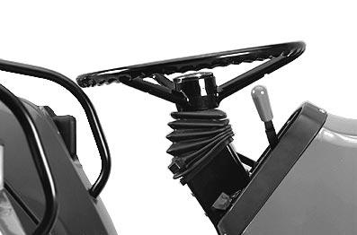
Steering
Steering Column-to-Dash Support Cap ScrewTorque71 N·m (52 lb-ft)
Steering Wheel NutTorque68 N·m (50 lb-ft)
Steering Valve Cap ScrewTorque30 N·m (22 lb-ft)
Steering Cylinder-to-Axle Cap Screws 2WDTorque200 N·m (147 lb-ft)
MFWDTorque94 N·m (69 lb-ft)
2WD Tie Rod Assembly Ball Joint-to-Steering RodTorque300 N·m (221 lb-ft)
Tie Rod Cap ScrewTorque90 N·m (66 lb-ft)
Tie Rod Lock NutTorque165 N·m (122 lb-ft)
MFWD Tie Rod Assembly Ball Joint-to-Steering RodTorque300 N·m (221 lb-ft)
Tie Rod Jam NutTorque120 N·m (89 lb-ft)
Tie Rod Lock NutTorque165 N·m (122 lb-ft)
on next page.
SECTION 60—STEERING AND BRAKE REPAIR—CONTINUED
Brakes
Outlet Fittings-to-Brake ValveTorque11 N·m (97 lb-in.)
Brake Valve-to-Panel Cap ScrewTorque70 N·m (52 lb-ft)
Inlet Check Valve Seat-to-Brake Valve HousingTorque73 N·m (54 lb-ft)
Pressure Equalizing Valve Plugto-Brake Valve HousingTorque37 N·m (27 lb-ft)
Spring Seat-to-Brake Valve HousingTorque92 N·m (68 lb-ft)
Return Compression Spring Assembliesto-Brake Actuator PlateTorque15 N·m (133 lb-in.)
SECTION 70—HYDRAULIC REPAIR
Hydraulic Pump
Flange-to-Engine Cap ScrewTorque50 N·m (37 lb-ft)
Bracket-to-Engine Cap ScrewTorque50 N·m (37 lb-ft)
Housing BoltTorque50 N·m (37 lb-ft)
Housing Cap ScrewTorque50 N·m (37 lb-ft)
Rear Outlet FittingTorque28 N·m (21 lb-ft)
Front Outlet FittingTorque46 N·m (34 lb-ft)
Shaft NutTorque55 N·m (41 lb-ft)
Bracket-to-Pump NutTorque50 N·m (37 lb-ft)
Hydraulic Filter Manifold-to-Transmission Case Cap ScrewTorque70 N·m (52 lb-ft)
Rockshaft
Draft-Sensing Support-to-Rockshaft Case Cap ScrewTorque375 N·m (277 lb-ft)
SECTION 70—HYDRAULIC REPAIR—CONTINUED
Rockshaft
Main Relief ValveTorque51 N·m (38 lb-ft)
Surge Relief ValveTorque34 N·m (25 lb-ft)
Rate-of-Drop ValveTorque50 N·m (37 lb-ft)
Rockshaft Valve-to-Inlet Housing Cap ScrewTorque13.6 N·m (120 lb-in.)
Inlet Housing-to-Rockshaft Case Cap ScrewTorque35 N·m (26 lb-ft)
Rockshaft Case-to-Differential Case Cap ScrewTorque125 N·m (92 lb-ft)
Hydraulic Pump Outlet Line FittingTorque60 N·m (45 lb-ft)
Rockshaft Bushing to Edge of BoreDistance7 mm (0.283 in.)
Dual SCV
Control Valve-to-Inlet Housing Cap ScrewTorque12 N·m (106 lb-in.)
Main Relief ValveTorque51 N·m (38 lb-ft)
Spool DetentTorque4 N·m (35 lb-in.)
Socket Head Cap ScrewTorque7 N·m (62 lb-in.)
Single (Third) SCV
Control Valve/End Plate-to-Inlet Housing Cap ScrewTorque12 N·m (106 lb-in.)
Spool Retainer ScrewTorque4 N·m (35 lb-in.)
Socket Head Cap ScrewTorque7 N·m (62 lb-in.)
SECTION 80—MISCELLANEOUS REPAIR
Pivot Pin Retainer-to-Front Support Cap ScrewTorque135 N·m (100 lb-ft)
2WD Front Axle-to-Front HousingClearance8 mm (0.030 in.)
Front Wheel-to-Hub Cap Screw (Steel)Torque175 N·m (130 lb-ft)
Front Wheel-to-Hub Cap Screw (Cast)Torque300 N·m (220 lb-ft)
Spindle-to-Axle NutTorque415 N·m (306 lb-ft)
Tie Rod End-to-Spindle Assembly NutTorque165 N·m (122 lb-ft)
Draft Link Support-to-Differential CaseTorque200 N·m (148 lb-ft)
Continued on next page.
-19-02MAR98
SECTION 80—MISCELLANEOUS REPAIR—CONTINUED
Draw Bar Support-to-Differential Case Cap Screws (M14x25) (6 used)Torque200 N·m (148 lb-ft) Cap Screws (M16x30) (4 used)Torque310 N·m (228 lb-ft)
SECTION 90—OPERATOR STATION REPAIR
Seat Support-to-Rockshaft Housing and Transmission CoverTorque125 N·m (92 lb-ft)
ROLL-GARD Mounting Cap ScrewTorque335 N·m (247 lb-ft)
Cab
Rear cab Frame Mounting Nuts-to-Final Drive Axle HousingTorque203 N·m (150 lb-ft.)
Cab Floor Plate Mounting Bracketto-Clutch Housing Cap ScrewsTorque110 N·m (80 lb-ft.)
Cab Floor Plate Mounting Bracketto-Floor Plate Cap ScrewsTorque203 N·m (150 lb-ft.)
LV,17161015,A6A-19-02MAR98
SERVICE RECOMMENDATIONS FOR O-RING BOSS FITTINGS
STRAIGHT FITTING
1. Inspect O-ring boss seat for dirt or defects.
2. Lubricate O-ring with petroleum jelly. Place electrical tape over threads to protect O-ring. Slide O-ring over tape and into O-ring groove of fitting. Remove tape.
3. Tighten fitting to torque value shown on chart.
ANGLE FITTING
1. Back-off lock nut (A) and back-up washer (B) completely to head-end (C) of fitting.
2. Turn fitting into threaded boss until back-up washer contacts face of boss.
3. Turn fitting head-end counterclockwise to proper index (maximum of one turn).
NOTE: Do not allow hoses to twist when tightening fittings.
4. Hold fitting head-end with a wrench and tighten locknut and back-up washer to proper torque value.
STRAIGHT FITTING OR SPECIAL
3/8-24UNF
7/16-20UNF
1/2-20UNF
9/16-18UNF
3/4-16UNF
7/8-14UNF
1-1/16-12UN
1-3/16-12UN
1-5/16-12UN
1-5/8-12UN
1-7/8-12UN
NOTE: Torque tolerance is ± 10%.
62.
102.
142.
46
75
105