


Operator Handbook 8 THIS HANDBOOK MUST BE KEPT IN THE MACHINE AT ALL TIMES 8 www.maskinisten.net DOWNLOAD SERVICE MANUAL JCBService WorldPartsCentre Waterloo Park Uttoxeter England ST14 5PA tel: +44 (0) 1889 - 590312 WWW.JCB.COM 2CX, BACKHOE LOADER MACHINES From Serial Number 930000 Publication Number 9801/8800 Jan 02 Issue 1
www.maskinisten.net
8 WARNING Study This Handbook Before Starting TheMachine
You must understand and follow the instructions in this handbook. You must observe all relevant laws and regulations. If you are unsure about anything, ask your JCB distributor or employer. Do not guess, you or others could be killed or seriously injured.
INT-1-1-1
8 CAUTION
Do not fit an attachment to this machine which is not JCB approved. Consult your JCB distributor before fitting any non approved attachment.
8-4-1-6
In this handbook and on the machine there are safety notices. Each notice starts with a signal word. The meanings of the signal words are given below.
8 DANGER
Denotes an extreme hazard exists. If proper precautions are not taken, it is highly probable that the operator (or others) could be killed or seriously injured.
INT-1-2-1
8 WARNING
Denotes a hazard exists. If proper precautions are not taken, the operator (or others) could be killed or seriously injured.
INT-1-2-2
8 CAUTION
Denotes a reminder of safety practices. Failure to follow these safety practices could result in injury to the operator (or others) and possible damage to the machine.
INT-1-2-3
MACHINE SECURITY
Vandalism and theft of unattended machines is an ever increasing problem and JCB is doing everything possible to help combat this.
JCB PLANTGUARD is a comprehensive package available to help you safeguard your machine. It includes such devices as vandal proof covers, window etching, immobiliser, concealed serial number, battery isolator, Tracker security system and much more.
Remember that the fitting of any one of these security devices will help to minimise not only the damage or loss of your machine but also subsequent lost productivity. It could also result in reduced insurance premiums.
Your JCB Distributor or Dealer will be pleased to provide information on any of these sensible precautions. ACT NOW!
INT-1-2-4
8800 - 1
SAFETY NOTICES www.maskinisten.net
8800 - 1 i CONTENTS INTRODUCTION Page Page Loader controls 38 - 41 Aboutthishandbook 1 Using this handbook 1 Units of measurement 1 Pagenumbering.................................................. 1 Left side, right side 1 Using the machine 1 The JCB 2CX Backhoe Loader 2 Safety - yours and others ................................. 3 Safety check list 3 - 6 General safety 3 Operating safety 4 Maintenance safety 5 - 6 Safety decals 7 Identifying your machine 8 - 9 Machine identification plate 8 Typical machine identification number................ 8 Typical engine identification number................... 8 Unit Identification 9 OPERATION Introduction 21 Before entering the cab.......................................... 21 - 22 Entering/leaving the cab Entering &leaving the cab................................... 23 Loader control lever lock..................................... 23 Doors and windows................................................. 24 - 25 Opening and closing the door 24 Opening and closing the front side window........ 24 Opening and closing the rear window................. 25 Radio console 25 Seat controls Option 1 - ‘Kab’ Type ......................................... 26 Option 2 - ‘Isringhausen’ Type 27 Seat belt 28 Fasten the seat belt 28 Release the seat belt 28 Check the seat belt is operating correctly .......... 28 Engineanddrivecontrols, switches and instruments...................................... 29 - 35 Controls 30 - 31 Switches 32 - 33 Instruments............................................................... 34 - 35 Airconditioningandheatercontrols 36 Fire extinguisher (when fitted) Using the fire extinguisher................................... 37 Standard shovel 39 Float, return to dig 40 6-in-1 clamshovel 41 Auxiliary spool .................................................... 41 Stabiliser controls 42 Backhoe controls....................................................43 - 52 JCB X pattern 43 - 45 JCB + pattern............................................................46 - 48 ISO pattern 49 - 51 Hydraclamps 52 Backhoe attachment control (if fitted) 52 Before starting the engine 53 Starting the engine 54 Jump-starting the engine 55 Preparing the machine for travel...........................56 - 59 Road travelling position....................................... 57 Site travelling position 59 Boom and slew locks..............................................60 - 61 Testing the parking brake 62 Getting the machine moving 63 - 64 Stopping and parking the machine 65 Site safety................................................................66 - 67 Working with the loader 68 - 69 Operating hints 68 Filling the loader shovel 68 Loading a truck 69 Getting the machine unstuck ............................. 69 Working with the backhoe 70 - 75 Operating hints 70 Preparing to use the backhoe 70 Removing a bucket 71 Fitting a bucket.................................................... 71 Digging 72 Sideshifting the backhoe..................................... 73 Lifting with the backhoe 74 Using the extending dipper 75 Operating in high and low temperatures ........ 76 Moving a disabled machine 77 Transportingthemachine 78 www.maskiinisten.net
8800 - 1 ii CONTENTS MAINTENANCE Page Page Fuelsystem......................................................... 125 - 127 Types of fuel........................................................ 125 Service requirements 101 Introduction 101 Maintenance........................................................ 101 Owner/Operator support 101 Service/Maintenance agreements....................... 101 Lifting regulations - inspections and tests 101 Lubricants - health and safety 102 Serviceschedules 103 - 105 Loader arm safety strut 106 Installing 106 Removing 106 Checking for damage 107 Cleaning the machine 107 Seat belt 108 Checking the seat belt condition and security.... 108 Obtaining replacement parts 108 ROPS/FOPS structure 109 Checking the ROPS/FOPSstructure 109 Fire extinguisher (when fitted) Checking the fire extinguisher............................. 109 Engine Panels Removing and fitting a side panel 110 Opening and closing the bonnet......................... 110 Greasing (daily)...................................................111 - 114 Greasing..............................................................115 - 117 Lubrication ......................................................... 118 Tyres and wheels 119 Tyre inflation 119 Checking the road wheel tightness 119 Engineairfilter....................................................120 - 121 Cleaning the pre-cleaner 120 Changing the elements 121 Engineoilandfilter 122 Checking the oil level 122 Changing the oil and filter ................................... 122 Engine cooling system 123 - 124 Adjusting the fan belt 123 Checking the coolant level 123 Changing the coolant 124 Fuel standards..................................................... 125 Low temperature fuels......................................... 125 Petrol 125 Filling the tank 125 Draining the fuel filter 126 Changing the filter element................................. 126 Draining/cleaning the sediment bowl 127 Bleeding the fuel system 127 Syncro shuttle transmission 128 Checking the oil level 128 Changing the oil and filter ................................... 128 Brakes 129 Parking brake adjustment 129 Checking the foot brake fluid level 129 Axles.................................................................... 130 - 131 Checking the differential oil level......................... 130 Changing the differential oil................................. 130 Checking the hub oil levels 131 Changing the hub oil 131 Hydraulic system Checking the fluid level 132 Changing the filter element 133 Electrical system Fuses 134 Relays ................................................................. 134 Link Box Fuses 135 Bulbs 135 Battery Warning Symbols 136 First aid - electrolyte ........................................... 137 Checking the electrolyte level 137 Cab heater Changing the filter 138 Windscreen washer 138 Stabiliser legs 139 Wear Pads 139 WearPad Adjustment 139 Aligning the roadwheels 140 Fluids,lubricants,capacitiesandspecifications Capacities and Lubricants................................... 141 Coolant mixtures 142 OPTIONAL ATTACHMENTS Introduction ....................................................... 151 Attachments available for your machine 151 www.maskiiinisten.net
www.masikiiinisten.net CONTENTS iii 8800 - 1 Page Quick Release Couplings 152 Quick release couplings - do's & don'ts 152 Connecting quick release couplings 152 Disconnecting quick release couplings............... 152 Excavator Quick Hitch 153 - 155 Installing the quick hitch...................................... 153 Removing the quick hitch.................................... 153 Installing excavator quick hitch attachments 154 Removing excavator quick hitch attachments.... 155
Lifting (craning) regulations 181 Safe working loads Backhoe Unit 181 Loader Unit 181 Backhoe bucket weights and dimensions Generalpurpose buckets (standard profile) 182 Grading buckets 182 Weights and dimensions 183 Tyresizesandpressures 184 Noiseand Vibration Data 185
SPECIFICATION
ABOUT THIS HANDBOOK
This handbook provides information for the 2CX Backhoe Loader range of Machines.
Serial No. 930000 onwards.
Using this Handbook
The illustrations in this handbook are for guidance only. Where the machines differ, the text and/or the illustration will specify.
This handbook is arranged to give you a good understanding of the machine and its safe operation. It also contains maintenance information and specification data. Read this handbook from front to back before using the machine for the first time. Particular attention must be given to all the safety aspects of operating and maintaining the machine.
General warnings in this chapter are repeated throughout the book, as well as specific warnings. Read all the safety statements regularly, so you do not forget them. Remember that the best operators are the safest operators.
Finally, treat this handbook as part of the machine. Keep it clean and in good condition. Do not operate the machine without a handbook in the cab. If there is anything you are not sure about, ask your JCB distributor or employer. Do not guess, you or others could be killed or seriously injured.
The manufacturer's policy is one of continuous improvement. The right to change the specification of the machine without notice is reserved. No responsibility will be accepted for discrepancies which may occur between specifications of the machine and the descriptions contained in this publication.
INT-1-2-5/1

Units of Measurement
In this handbook, the S.I. system of units is used. For example, liquid capacities are given in litres. The Imperial units follow in parenthesis () - for example 28 litres (6 gal).
Page Numbering
The page numbering system in this handbook is not continuous. There is a gap of a few pages between sections. This allows for the insertion of new pages in later issues of the handbook.
Left Side, Right Side
In this handbook, 'left' A and 'right' B mean your left and right when you are seated correctly in the machine. This is so whether you are facing the loader (front) or the backhoe (rear).
Using the Machine
The 2CX range of machines can do many jobs. If these jobs are to be done well and safely you must know the machine, its controls and its safe operation. It is not a training manual on the art of loading. If you are a new operator, get yourself trained in the skills of using a backhoe loader before trying to work with it. If you don't, you will not do your job well, and you will be a danger to yourself and others. S137100
www.mas1kinisten.net INTRODUCTION 1 8800 - `1
THE JCB 2CX BACKHOE LOADER


Machine Description

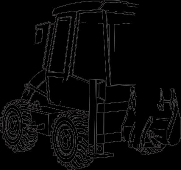
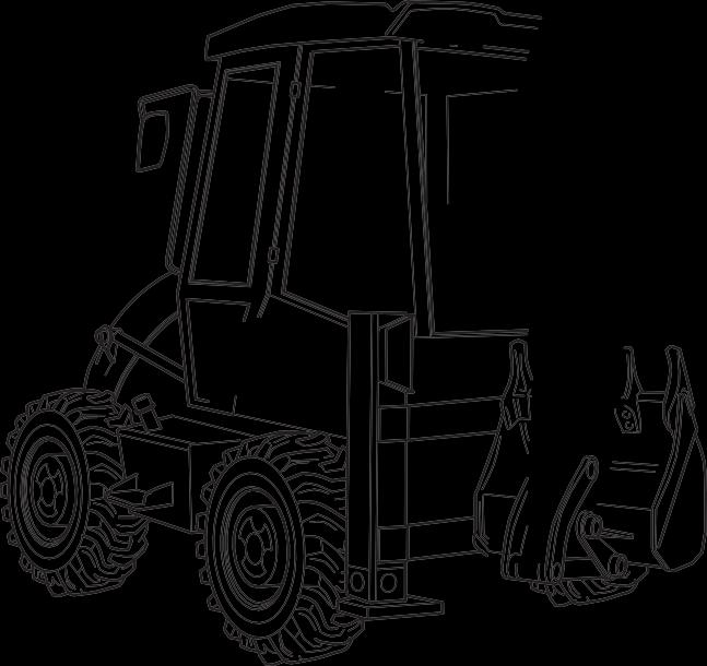
The backhoe loader is a self propelled wheeled machine with a main structural support designed to carry both a front mounted bucket loading mechanism and a rear mounted backhoe. When used in the backhoe mode, the machine normally digs below ground level with bucket motion towards the machine; the backhoe lifts, swings and discharges material while the machine is stationary. When used in the loader mode, the machine loads or excavates through forward motion of the machine, and lifts, transports and discharges material.
www.mas2kinisten.net INTRODUCTION 2 8800 - 1
SHOVEL BATTERY COVER 393841 DIPPER BOOM
LEG BUCKET HYDRAULIC TANK SIGHT GLASS 393842
ROPS/FOPS CAB FUEL FILLER CAP LOADER ARM
STABILISER
SAFETY - YOURS AND OTHERS
All construction and agricultural equipment can be hazardous. When a backhoe loader is correctly operated and properly maintained, it is a safe machine to work with. But when it is carelessly operated or poorly maintained it can become a danger to you (the operator) and others.
In this handbook and on the machine you will find warning messages. Read and understand them. They tell you of potential hazards and how to avoid them. If you do not fully understand the warning messages, ask your employer or JCB distributor to explain them.
But safety is not just a matter of responding to the warnings. All the time you are working on or with the machine you must be thinking what hazards there might be and how to avoid them.
General Safety
8 WARNING Handbook
Do not work with the machine until you are sure that you can control it.
Do not start any job until you are sure that you and those around you will be safe.
If you are unsure of anything, about the machine or the job, ask someone who knows. Do not assume anything.
Remember
BECAREFUL BE ALERT BE SAFE
INT-1-3-1/1
As well as general warnings in this chapter, specific warnings are given throughout the book. Read all safety statements regularly, so you do not forget them.
SAFETY CHECK LIST
You and others can be injured if you operate or maintain the machine without first studying this handbook. Read the safety instructions before operating the machine. If you do not understand anything, ask your employer or JCB distributor to explain it. Keep this handbook clean and in good condition. Do not operate the machine without a handbook in the cab, or if there is anything on the machine you do not understand.
INT-1-3-2
8 WARNING Clothing
You can be injured if you do not wear the proper clothing. Loose clothing can get caught in the machinery. Wear protective clothing to suit the job. Examples of protective clothing are: a hard hat, safety shoes, safety glasses, a well fitting overall, ear-protectors and industrial gloves. Keep cuffs fastened. Do not wear a necktie or scarf. Keep long hair restrained.
INT-1-3-6
8 WARNING Machine Modifications
This machine is manufactured in compliance with legislative and other requirements. It should not be altered in any way which would affect or invalidate any of these requirements. For advice consult your JCB Distributor.
Reference should also be made to Optional Attachments section where appropriate.
INT-1-3-10
8 WARNING Alcohol and Drugs
It is extremely dangerous to operate machinery when under the influence of alcohol or drugs. Do not consume alcoholic drinks or take drugs before or whilst operating the machine or attachments. Be aware of medicines which can cause drowsiness.
INT-1-3-9
8 CAUTION Passengers
Passengers in or on the machine can cause accidents. The JCB Backhoe Loader is a one-man machine. Do not carry passengers.
INT-2-2-2
8 WARNING
RaisedAttachments
Raised attachments can fall and injure you. Do not walk or work under raised attachments unless they are safely blocked.
INT-1-3-8
8 CAUTION Regulations
Obey all laws, work site and local regulations which affect you and your machine.
INT-1-3-3
8
WARNING Care and Alertness
All the time you are working with or on the machine, take care and stay alert. Always be careful. Always be alert for hazards.
INT-1-3-5
www.mas3kinisten.net INTRODUCTION 3 8800 - 1
SAFETY CHECK LIST (continued)
Operating Safety
8 WARNING Machine Condition
A defective machine can injure you or others. Do not operate a machine which is defective or has missing parts. Make sure the maintenance procedures in this handbook are completed before using the machine.
INT-2-1-2
8 WARNING Lifting Equipment
You can be injured if you use faulty lifting equipment. Make sure that lifting equipment is in good condition. Make sure that lifting tackle complies with all local regulations and is suitable for the job. Make sure that lifting equipment is strong enough for the job.
INT-1-3-7
8 WARNING Engine
The engine has rotating parts. Do not open the engine cover while the engine is running. Do not use the machine with the cover open.
INT-2-1-6
8 WARNING Machine Limits
Operating the machine beyond its design limits can damage the machine, it can also be dangerous. Do not operate the machine outside its limits. Do not try to upgrade the machine performance with unapproved modifications.
INT-2-1-4
8 WARNING Controls
You and others can be killed or injured if you operate the control levers from outside the cab. Operate the control levers only when you are seated correctly in the cab.
INT-2-1-3
8 WARNING Road Wheel Alignment
At the start of each working period, and at least once a day, or if having difficulty in steering, check and, if necessary, re-align the road wheels.
2-1-1-10
8 WARNING Visibility
Accidents can be caused by working in poor visibility. Keep windows clean and use your lights to improve visibility. Do not operate the machine if you cannot see properly.
INT-2-1-11
8 WARNING
Electrical Circuits
Understand the electrical circuit before connecting or disconnecting an electrical component. A wrong connection can cause injury and/or damage.
INT-3-1-4
8 WARNING Ramps and Trailers
Water, mud, ice, grease and oil on ramps or trailers can cause serious accidents. Make sure ramps and trailers are clean before driving onto them. Use extreme caution when driving onto ramps and trailers.
INT-2-2-6
8 WARNING SafetyBarriers
Unguarded machines in public places can be dangerous. In public places, or where your visibility is reduced, place barriers around the work area to keep people away.
INT-2-2-8
8 WARNING Parking
An incorrectly parked machine can move without an operator. Follow the instructions in this handbook to park the machine correctly.
INT-2-2-4
8 WARNING
Hazardous Atmospheres
This machine is designed for use in normal out door atmospheric conditions. It should not be used in an enclosed area without adequate ventilation. Do not use the machine in a potentially explosive atmosphere, i.e. combustible vapours, gas or dust, without first consulting your JCB Distributor.
INT-2-1-14
8 DANGER Sparks
Explosions and fire can be caused by sparks from the exhaust or the electrical system. Do not use the machine in closed areas where there is flammable material, vapour or dust.
INT-2-2-10
www.mas4kinisten.net INTRODUCTION 4 8800 - 1
SAFETY CHECK LIST (continued)
Maintenance Safety
8 WARNING Modifications and Welding
Non-approved modifications can cause injury and damage. Parts of the machine are made from cast iron; welds on cast iron can weaken the structure and break. Do not weld cast iron. Contact your JCB dealer before modifying the machine.
INT-3-1-2/1
8 WARNING Metal Splinters
You can be injured by flying metal splinters when driving metal pins in or out. Use a soft faced hammer or drift to remove and fit metal pins. Always wear safety glasses.
INT-3-1-3
8 WARNING SafetyStrut
Raised loader arms can drop suddenly and cause serious injury. Before working under raised loader arms, fit the loader arm safety strut.
2-1-1-6
8 WARNING Communications
Bad communications can cause accidents. If two or more people are working on the machine, make sure each is aware of what the others are doing. Before starting the engine make sure the others are clear of the danger areas; examples of danger areas are: the rotating blades and belt on the engine, the attachments and linkages, and anywhere beneath or behind the machine. People can be killed or injured if these precautions are not taken.
INT-3-1-5
8 WARNING Counterweights
Your machine may be fitted with counterweights. They are extremely heavy. Do not attempt to remove them.
INT-3-2-5
8 WARNING Fires
If your machine is equipped with a fire extinguisher, make sure it is checked regularly. Keep it in the operator's cab until you need to use it.
Do not use water to put out a machine fire, you could spread an oil fire or get a shock from an electrical fire. Use carbon dioxide, dry chemical or foam extinguishers. Contact your nearest fire department as quickly as possible. Firefighters should use self-contained breathing apparatus.
INT-3-2-7/1
8 WARNING Battery Terminals
The machine is negatively earthed. Always connect the negative pole of the battery to earth.
When connecting the battery, connect the earth (-) lead last.
When disconnecting the battery, disconnect the earth (-) lead first.
INT-3-1-9
8 WARNING Repairs
Do not try to do repairs or any other type of maintenance work you do not understand. Get a Service Manual from your JCB distributor, or get the work done by a specialist engineer.
INT-3-1-1
8 WARNING
Hydraulic Pressure
Hydraulic fluid at system pressure can injure you. Before disconnecting or connecting hydraulic hoses, stop the engine and operate the controls to release pressure trapped in the hoses. Make sure the engine cannot be started while the hoses are open.
INT-3-1-11/1
8 WARNING
Hydraulic hoses
Damaged hoses can cause fatal accidents. Inspect the hoses regularly for:
Damaged end fittings
Chafed outer covers
Ballooned outer covers
Kinked orcrushed hoses
Embedded armouring in outer covers
Displaces end fittings.
INT- 3-3-2
8 WARNING Accumulators
The accumulators contain hydraulic oil and gas at high pressure. Prior to any work being carried out on the braking system they must be discharged by a JCB distributor as the sudden release of the hydraulic oil or gas may cause injury.
7-1-1-4
www.mas5kinisten.net INTRODUCTION 5 8800 - 1
SAFETY CHECK LIST (continued)
Maintenance Safety (continued)
8 WARNING
Fluoroelastomeric Materials
Certain seals and gaskets (e.g. crankshaft oil seal) on JCB machines contain fluoroelastomeric materials such as Viton, Fluorel and Technoflon. Fluoroelastomeric materials subjected to high temperatures can produce highly corrosive hydrofluoric acid. THIS ACID CAN SEVERELY BURN.
New fluoroelastomeric components at ambient temperature require no special safety precautions.
Used fluoroelastomeric components whose temperatures have not exceeded 300°C require no special safety precautions. If evidence of decomposition (e.g. charring) is found, refer to the next paragraph for safety instructions DO NOT TOUCH COMPONENT OR SURROUNDING AREA.
Used fluoroelastomeric components subjected to temperatures greater than 300°C (e.g. engine fire) must be treated using the following safety procedure. Make sure that heavy duty gloves and special safety glasses are worn:
1 Ensure that components have cooled then remove and place material into plastic bags.
2 Thoroughly wash contaminated area with 10% calcium hydroxide or other suitable alkali solution, if necessary use wire wool to remove burnt remains.
3 Thoroughly wash contaminated area with detergent and water.
4 Contain all removed material, gloves etc. used in this operation in sealed plastic bags and dispose of in accordance with Local Authority Regulations.
DO NOT BURN FLUOROELASTOMERIC MATERIALS.
If contamination of skin or eyes occurs, wash the affected area with a continuous supply of clean water or with calcium hydroxide solution for 15-60 minutes. Get medical attention immediately.
INT-3-3-5/1
8 WARNING
Under no circumstances must the engine be run with the transmission in gear and only one driving wheel jacked clear of the ground, since the wheel on the ground will move the machine.
INT-3-1-16
www.mas6kinisten.net INTRODUCTION 6 8800 - 1
SAFETY DECALS
Decals on the machine warn you of particular hazards. Each decal is attached close to a part of the machine where there is a possible hazard. Read and make sure you understand the safety message before you work with or on that part of the machine.
Keep all decals clean and readable. Replace lost or damaged decals. The decals and their attachment points are shown on the following pages. Each decal has a part number printed on it, use this number to order a new decal from your JCB distributor.
INT-3-3-3
8 WARNING
If you need eye-glasses for reading, make sure you wear them when reading the safety decals. Decals are strategically placed around the machine to remind you of possible hazards. Do not over-stretch or place yourself in dangerous positions to read the decals.
INT-3-3-4
8 WARNING Decals
You can be injured if you do not obey the decal safety instructions. Keep decals clean. Replace unreadable or missing decals with new ones before operating the machine. Make sure replacement parts include warning decals where necessary.
INT-1-3-4

www.mas7kinisten.net INTRODUCTION 7 8800 - 1
S227220
IDENTIFYING YOUR MACHINE
Machine Identification Plate
Your machine has an identification plate X mounted on the loader tower as shown. The serial numbers of the machine and its major units are stamped on the plate.
The serial number of each major unit is also stamped on the unit itself. If a major unit is replaced by a new one, the serial number on the identification plate will be wrong. Either stamp the new number of the unit on the identification plate, or simply stamp out the old number. This will prevent the wrong unit number being quoted when replacement parts are ordered.
The machine and engine serial numbers can help identify exactly the type of equipment you have.
Typical Machine Identification Number
SLP 2CX T S R E 123456
A World Manufacturer Identification
B Machine Model
�� Steer Type(T= 2WS, F=4WS)

�� Build Type(S=Sideshift, C=Centremount, L=Loader)
E Year of Manufacture:

1 = 2001
2 = 2002
3 = 2003
4 = 20047
5 = 2005
6 = 2006
7 = 2007
8 = 2008
F Manufacturer Location (E = England)
G MachineSerialNumber
Typical Engine Identification Number AB 50262 U 500405 P A B �� �� E
A Engine Type AB = 4 cylinder turbo
B Build Number
�� Country of Origin
�� Engine Sequence Number
E Year of Manufacture
www.mas8kinisten.net INTRODUCTION 8 8800 - 1
A B �� �� E 0 ⮊
X
S227230
IDENTIFYING YOUR MACHINE
Unit Identification


The engine serial number is stamped on a label Y which is fastened to the left side of the cylinder block (looking from the rear).
The Syncro Shuttle serial number is stamped on a label Z which is mounted to the rear face of the unit.


The rear axle serial number is stamped on a plate W mounted to the front face of the axle, just above the propshaft coupling.
The front axle serial number is stamped on a plate V mounted to the rear face of the axle.
www.mas9kinisten.net INTRODUCTION 9 8800 - 1 Y
W
S181760
Z
V
S175510
S181770
S175520
www.maskinisten.net
This chapter is arranged to guide you step-by-step through the task of learning how to use the machine. Read it through from beginning to end. By the end of the chapter you should have a good understanding of the machine and how to operate it.
Pay particular attention to all safety messages. They are there to warn you of possible hazards. Do not just read them; think about what they mean. Understand the hazards and how to avoid them.
If there is anything you do not understand, ask your JCB distributor. He will be pleased to advise you.
When you have learned where the driving controls are and what they do, practice using them. Practice driving the machine in a safe, open space clear of other people.
Get to know the 'feel' of the machine and its driving controls. Move on to the attachment controls only when you can drive the machine confidently and safely.
Take great care when practicing with the attachment controls. Practice in an open space. Keep people clear. Do not jerk the controls; operate them slowly until you understand the effect they have on the machine.
Finally, do not rush the job of learning. Take your time and take it safely.
BEFORE ENTERING THE CAB
The following checks should be made each time you return to the machine after leaving it for any period of time. We advise you also to stop the machine occasionally during long work sessions and do the checks again.
All these checks concern the serviceability of the machine. Some concern your safety. Get your service engineer to check and correct any defects.
8 WARNING
Walking or working under raised attachments can be hazardous. You could be crushed by the attachments or get caught in the linkages.
Lower the attachments to the ground before doing these checks. If you are new to this machine, get an experienced operator to lower them for you.
If there is nobody to help you, study this handbook until you have learned how to lower the attachments. Also make sure that the parking brake is engaged before doing these checks.
2-2-1-1
1 Check for Cleanliness
a Clean the windows, light lenses and rear view mirrors.
b Remove dirt and debris, especially from around the linkages, rams, pivot points and radiator.
c Make sure the cab step and handholds are clean and dry.
d Clean all safety decals. Replace any that are missing or cannot be read.
2 Check for Damage
a Inspect the machine generally for damaged and missing parts.
b Make sure that the shovel, bucket and their teeth are secure and in good condition.
c Make sure that all pivot pins are secured correctly in place.
d Inspect the windows for cracks and damage. Glass splinters can blind you.
e Check for oil, fuel and coolant leakages beneath the machine.
8 WARNING
You could be killed or injured if a machine tyre bursts. Do not use the machine with damaged, incorrectly inflated or excessively worn tyres.
2-2-1-2
www ma2s1kinisten net OPERATION 21 8800 - 1
INTRODUCTION
Remember BECAREFUL BE ALERT BE SAFE
3 Check the Tyres
BEFORE ENTERING THE CAB (continued)
a Make sure the tyres are correctly inflated. See Tyres and Wheels (MAINTENANCE section) for a safe procedure for inflating the tyres.
b Check for cut rubber and penetration by sharp objects. Do not use a machine with damaged tyres.


4 Check the Engine Panels and Fuel/Hydraulic Fluid Filler Caps
a Make sure the engine panels are fitted and secure.
b Make sure the hydraulic fluid filler cap A and fuel filler cap B are tightly closed. (We also recommend that you lock the filler caps.)
B

www ma2s2kinisten net OPERATION 22 8800 - 1
A 391640
391650
ENTERING/LEAVING THE CAB
Entering & Leaving the Cab
8 WARNING


Entering and leaving the cab or canopy must only be made where steps and handrails are provided. Always face the machine when entering and leaving. Make sure the step(s), handrails and your boot soles are clean and dry. Do not jump from the machine. Do not use the machine controls as handholds, use the handrails.
INT-2-1-7/1

Make sure the machine is stopped and correctly parked before entering or leaving the cab. When you get on and off the machine always maintain a three point contact with the handrails and step as shown at A. Do not use the machine controls or steering wheel as handholds.
Loader Control Lever Lock (if fitted)

To prevent the loader arms and the backhoe from being accidentally operated when the driver is entering or leaving the cab, or driving on the highway, safety locking pins X can be installed.


Always fit the locking pin before leaving the cab. Only remove the locking pin when you are correctly seated inside the cab. Put the pins in their stowage position during machine operation. This will prevent the pin from being misplaced.

www ma2s2kinisten net OPERATION 23 8800 - 1
X 393540 A 391460
DOOR AND WINDOWS
The cab has one door, an opening rear window, an opening front side window and two non-opening rear side windows.
Opening and Closing the Door
To open the door from the outside, unlock it with the key provided and press the lock barrel A. The door is fitted with an assister which will spring it open and hold it open.

Close the door from the inside by pulling it firmly; it will latch itself. To open the door from the inside, pull lever B up.


If extension rod F is fitted, the door can be latched partly open; swing extension rod F towards the door and hold it there while you pull the door onto it. Make sure the door latches fully onto the extension rod.

Note: Do not drive the machine with the door unlatched. Otherwise it could swing open.
Opening and Closing the Front Side Window
To open the front side window, push lever C toward the rear of the machine then lift lever, while pushing window outwards, until it latches down. To close the window, first lift the lever then pull the window inwards, lower the lever and latch it.


The window can be opened fully and secured to the rear side window. Open the window then pull lever C rearward a little way to unhook it from its pin on the frame.
Swing the window right round to meet the outside of the rear side window. Push the window firmly against the rear side window to engage the knob D into rubber socket E
To close the window, pull firmly to disengage knob D from rubber socket E. Swing the window closed and set lever C back on its pin. Then close the window as described above.

www ma2s2kinisten net OPERATION 24 8800 - 1
A S145870 E �� S136650 �� S136640 0 ® S181860
DOORS AND WINDOWS (continued)
Opening and Closing the Rear Window
To open the rear window, take a firm grip on the two handles A and press lever B on both sides to release the lock mechanism.
Pull the window towards the front of the machine and up as far as it will go. Release lever B then make sure the window latches in the open position.
To close the window, press lever B on both sides to release the lock mechanism then lower the window to the closed position. Release lever B then make sure the window latches in the closed position.
Removing/Installing the Radio
RADIO CONSOLE

If your machine has a radio fitted we suggest that you remove the radio from its carrier at the end of each working day.


To remove the radio, gently pull radio carrier handle C. To install, make sure you have the radio positioned the correct way up. Otherwise you may damage the connecting pins. Gently push the radio into position.

www ma2s2kinisten net OPERATION 25 8800 - 1
® A S223620 �� 391811
Option 1 - ‘Kab’ Type
The operator's seat can be adjusted for your comfort. A correctly adjusted seat will reduce operator fatigue. Position the seat so that you can comfortably reach the machine controls. For driving the machine, adjust the seat so that you can depress the brake pedal fully with your back against the seat back.
The seat can be turned to face the backhoe controls. Remember to adjust it again if necessary.
8 WARNING
When turning the seat, always turn away from the loader controls. Otherwise your legs could knock the control levers.
2-2-1-7
The seat adjustments are as follows:
Fore/Aft
Move lever 4 upwards and slide the seat to the position you want. Release lever 4. Make sure the seat is locked in position.
Height/Weight
Sit on the seat. Pull knob 1 forward to disengage and slide it fully horizontal in the + direction.
Operate ratchet handle 2 to adjust the seat up or down to the desired height.
A light driver will require the pointer 3 to be close to the 'small person' symbol. To adjust the pointer in this direction operate the ratchet handle 2 with its - sign adjacent to the metal lug.


For a heavier driver, reverse the ratchet handle 2 by pulling and twisting through 180° so the + sign is adjacent to the lug and then operate the handle to bring the pointer close to the 'large person' symbol.
If the upwards travel of the seat is excessive, adjust the control knob 1 in the - direction to restrict the upwards motion.
Swivel
Push lever 5 down. Swivel the seat to face the opposite direction. Release lever 5. Make sure the seat latches in position.

4 5 2 1 3
S181900
www ma2s2kinisten net OPERATION 26 8800 - 1
SEAT CONTROLS