12 minute read
SAFETY CHECK LIST (continued)

Operating Safety
8 WARNING Machine Condition
Advertisement
A defective machine can injure you or others. Do not operate a machine which is defective or has missing parts. Make sure the maintenance procedures in this handbook are completed before using the machine.
INT-2-1-2
8 WARNING Lifting Equipment
You can be injured if you use faulty lifting equipment. Make sure that lifting equipment is in good condition. Make sure that lifting tackle complies with all local regulations and is suitable for the job. Make sure that lifting equipment is strong enough for the job.
INT-1-3-7
8 WARNING Engine
The engine has rotating parts. Do not open the engine cover while the engine is running. Do not use the machine with the cover open.
INT-2-1-6
8 WARNING Machine Limits
Operating the machine beyond its design limits can damage the machine, it can also be dangerous. Do not operate the machine outside its limits. Do not try to upgrade the machine performance with unapproved modifications.
INT-2-1-4
8 WARNING Controls
You and others can be killed or injured if you operate the control levers from outside the cab. Operate the control levers only when you are seated correctly in the cab.
INT-2-1-3
8 WARNING Road Wheel Alignment
At the start of each working period, and at least once a day, or if having difficulty in steering, check and, if necessary, re-align the road wheels.
2-1-1-10
8 WARNING Visibility
Accidents can be caused by working in poor visibility. Keep windows clean and use your lights to improve visibility. Do not operate the machine if you cannot see properly.
INT-2-1-11
8 WARNING
Electrical Circuits
Understand the electrical circuit before connecting or disconnecting an electrical component. A wrong connection can cause injury and/or damage.
INT-3-1-4
8 WARNING Ramps and Trailers
Water, mud, ice, grease and oil on ramps or trailers can cause serious accidents. Make sure ramps and trailers are clean before driving onto them. Use extreme caution when driving onto ramps and trailers.
INT-2-2-6
8 WARNING SafetyBarriers
Unguarded machines in public places can be dangerous. In public places, or where your visibility is reduced, place barriers around the work area to keep people away.
INT-2-2-8
8 WARNING Parking
An incorrectly parked machine can move without an operator. Follow the instructions in this handbook to park the machine correctly.
INT-2-2-4
8 WARNING
Hazardous Atmospheres
This machine is designed for use in normal out door atmospheric conditions. It should not be used in an enclosed area without adequate ventilation. Do not use the machine in a potentially explosive atmosphere, i.e. combustible vapours, gas or dust, without first consulting your JCB Distributor.
INT-2-1-14
8 DANGER Sparks
Explosions and fire can be caused by sparks from the exhaust or the electrical system. Do not use the machine in closed areas where there is flammable material, vapour or dust.
INT-2-2-10
SAFETY CHECK LIST (continued)
Maintenance Safety
8 WARNING Modifications and Welding
Non-approved modifications can cause injury and damage. Parts of the machine are made from cast iron; welds on cast iron can weaken the structure and break. Do not weld cast iron. Contact your JCB dealer before modifying the machine.
INT-3-1-2/1
8 WARNING Metal Splinters
You can be injured by flying metal splinters when driving metal pins in or out. Use a soft faced hammer or drift to remove and fit metal pins. Always wear safety glasses.
INT-3-1-3
8 WARNING SafetyStrut
Raised loader arms can drop suddenly and cause serious injury. Before working under raised loader arms, fit the loader arm safety strut.
2-1-1-6
8 WARNING Communications
Bad communications can cause accidents. If two or more people are working on the machine, make sure each is aware of what the others are doing. Before starting the engine make sure the others are clear of the danger areas; examples of danger areas are: the rotating blades and belt on the engine, the attachments and linkages, and anywhere beneath or behind the machine. People can be killed or injured if these precautions are not taken.
INT-3-1-5
8 WARNING Counterweights
Your machine may be fitted with counterweights. They are extremely heavy. Do not attempt to remove them.
INT-3-2-5
8 WARNING Fires
If your machine is equipped with a fire extinguisher, make sure it is checked regularly. Keep it in the operator's cab until you need to use it.
Do not use water to put out a machine fire, you could spread an oil fire or get a shock from an electrical fire. Use carbon dioxide, dry chemical or foam extinguishers. Contact your nearest fire department as quickly as possible. Firefighters should use self-contained breathing apparatus.
INT-3-2-7/1
8 WARNING Battery Terminals
The machine is negatively earthed. Always connect the negative pole of the battery to earth.
When connecting the battery, connect the earth (-) lead last.
When disconnecting the battery, disconnect the earth (-) lead first.
INT-3-1-9
8 WARNING Repairs
Do not try to do repairs or any other type of maintenance work you do not understand. Get a Service Manual from your JCB distributor, or get the work done by a specialist engineer.
INT-3-1-1
8 WARNING
Hydraulic Pressure
Hydraulic fluid at system pressure can injure you. Before disconnecting or connecting hydraulic hoses, stop the engine and operate the controls to release pressure trapped in the hoses. Make sure the engine cannot be started while the hoses are open.
INT-3-1-11/1
8 WARNING
Hydraulic hoses
Damaged hoses can cause fatal accidents. Inspect the hoses regularly for:
Damaged end fittings
Chafed outer covers
Ballooned outer covers
Kinked orcrushed hoses
Embedded armouring in outer covers
Displaces end fittings.
INT- 3-3-2
8 WARNING Accumulators
The accumulators contain hydraulic oil and gas at high pressure. Prior to any work being carried out on the braking system they must be discharged by a JCB distributor as the sudden release of the hydraulic oil or gas may cause injury.
7-1-1-4
SAFETY CHECK LIST (continued)
Maintenance Safety (continued)
8 Warning
Fluoroelastomeric Materials
Certain seals and gaskets (e.g. crankshaft oil seal) on JCB machines contain fluoroelastomeric materials such as Viton, Fluorel and Technoflon. Fluoroelastomeric materials subjected to high temperatures can produce highly corrosive hydrofluoric acid. THIS ACID CAN SEVERELY BURN.
New fluoroelastomeric components at ambient temperature require no special safety precautions.
Used fluoroelastomeric components whose temperatures have not exceeded 300°C require no special safety precautions. If evidence of decomposition (e.g. charring) is found, refer to the next paragraph for safety instructions DO NOT TOUCH COMPONENT OR SURROUNDING AREA.
Used fluoroelastomeric components subjected to temperatures greater than 300°C (e.g. engine fire) must be treated using the following safety procedure. Make sure that heavy duty gloves and special safety glasses are worn:
1 Ensure that components have cooled then remove and place material into plastic bags.
2 Thoroughly wash contaminated area with 10% calcium hydroxide or other suitable alkali solution, if necessary use wire wool to remove burnt remains.
3 Thoroughly wash contaminated area with detergent and water.
4 Contain all removed material, gloves etc. used in this operation in sealed plastic bags and dispose of in accordance with Local Authority Regulations.
DO NOT BURN FLUOROELASTOMERIC MATERIALS.
If contamination of skin or eyes occurs, wash the affected area with a continuous supply of clean water or with calcium hydroxide solution for 15-60 minutes. Get medical attention immediately.
INT-3-3-5/1
8 Warning
Under no circumstances must the engine be run with the transmission in gear and only one driving wheel jacked clear of the ground, since the wheel on the ground will move the machine.
INT-3-1-16
Safety Decals
Decals on the machine warn you of particular hazards. Each decal is attached close to a part of the machine where there is a possible hazard. Read and make sure you understand the safety message before you work with or on that part of the machine.
Keep all decals clean and readable. Replace lost or damaged decals. The decals and their attachment points are shown on the following pages. Each decal has a part number printed on it, use this number to order a new decal from your JCB distributor.
INT-3-3-3
8 Warning
If you need eye-glasses for reading, make sure you wear them when reading the safety decals. Decals are strategically placed around the machine to remind you of possible hazards. Do not over-stretch or place yourself in dangerous positions to read the decals.
INT-3-3-4
8 WARNING Decals
You can be injured if you do not obey the decal safety instructions. Keep decals clean. Replace unreadable or missing decals with new ones before operating the machine. Make sure replacement parts include warning decals where necessary.
INT-1-3-4
Identifying Your Machine
Machine Identification Plate
Your machine has an identification plate X mounted on the loader tower as shown. The serial numbers of the machine and its major units are stamped on the plate.
The serial number of each major unit is also stamped on the unit itself. If a major unit is replaced by a new one, the serial number on the identification plate will be wrong. Either stamp the new number of the unit on the identification plate, or simply stamp out the old number. This will prevent the wrong unit number being quoted when replacement parts are ordered.
The machine and engine serial numbers can help identify exactly the type of equipment you have.
Typical Machine Identification Number
SLP 2CX T S R E 123456
A World Manufacturer Identification
B Machine Model
�� Steer Type(T= 2WS, F=4WS)

�� Build Type(S=Sideshift, C=Centremount, L=Loader)
E Year of Manufacture:
1 = 2001
2 = 2002
3 = 2003
4 = 20047
5 = 2005
6 = 2006
7 = 2007
8 = 2008
F Manufacturer Location (E = England)
G MachineSerialNumber
Typical Engine Identification Number AB 50262 U 500405 P A B �� �� E
A Engine Type AB = 4 cylinder turbo
B Build Number
�� Country of Origin
�� Engine Sequence Number
E Year of Manufacture
Identifying Your Machine
Unit Identification


The engine serial number is stamped on a label Y which is fastened to the left side of the cylinder block (looking from the rear).
The Syncro Shuttle serial number is stamped on a label Z which is mounted to the rear face of the unit.
The rear axle serial number is stamped on a plate W mounted to the front face of the axle, just above the propshaft coupling.
The front axle serial number is stamped on a plate V mounted to the rear face of the axle.
This chapter is arranged to guide you step-by-step through the task of learning how to use the machine. Read it through from beginning to end. By the end of the chapter you should have a good understanding of the machine and how to operate it.
Pay particular attention to all safety messages. They are there to warn you of possible hazards. Do not just read them; think about what they mean. Understand the hazards and how to avoid them.
If there is anything you do not understand, ask your JCB distributor. He will be pleased to advise you.
When you have learned where the driving controls are and what they do, practice using them. Practice driving the machine in a safe, open space clear of other people.
Get to know the 'feel' of the machine and its driving controls. Move on to the attachment controls only when you can drive the machine confidently and safely.
Take great care when practicing with the attachment controls. Practice in an open space. Keep people clear. Do not jerk the controls; operate them slowly until you understand the effect they have on the machine.
Finally, do not rush the job of learning. Take your time and take it safely.
Before Entering The Cab
The following checks should be made each time you return to the machine after leaving it for any period of time. We advise you also to stop the machine occasionally during long work sessions and do the checks again.
All these checks concern the serviceability of the machine. Some concern your safety. Get your service engineer to check and correct any defects.
8 Warning
Walking or working under raised attachments can be hazardous. You could be crushed by the attachments or get caught in the linkages.
Lower the attachments to the ground before doing these checks. If you are new to this machine, get an experienced operator to lower them for you.
If there is nobody to help you, study this handbook until you have learned how to lower the attachments. Also make sure that the parking brake is engaged before doing these checks.
2-2-1-1
1 Check for Cleanliness a Clean the windows, light lenses and rear view mirrors. b Remove dirt and debris, especially from around the linkages, rams, pivot points and radiator. c Make sure the cab step and handholds are clean and dry. d Clean all safety decals. Replace any that are missing or cannot be read.
2 Check for Damage
a Inspect the machine generally for damaged and missing parts.
b Make sure that the shovel, bucket and their teeth are secure and in good condition.
c Make sure that all pivot pins are secured correctly in place.
d Inspect the windows for cracks and damage. Glass splinters can blind you.
e Check for oil, fuel and coolant leakages beneath the machine.
8 Warning
You could be killed or injured if a machine tyre bursts. Do not use the machine with damaged, incorrectly inflated or excessively worn tyres.
2-2-1-2
3 Check the Tyres
BEFORE ENTERING THE CAB (continued)
a Make sure the tyres are correctly inflated. See Tyres and Wheels (MAINTENANCE section) for a safe procedure for inflating the tyres.
b Check for cut rubber and penetration by sharp objects. Do not use a machine with damaged tyres.

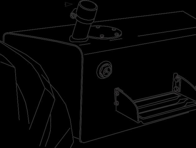
4 Check the Engine Panels and Fuel/Hydraulic Fluid Filler Caps a Make sure the engine panels are fitted and secure. b Make sure the hydraulic fluid filler cap A and fuel filler cap B are tightly closed. (We also recommend that you lock the filler caps.)
B
ENTERING/LEAVING THE CAB
Entering & Leaving the Cab
8 Warning
Entering and leaving the cab or canopy must only be made where steps and handrails are provided. Always face the machine when entering and leaving. Make sure the step(s), handrails and your boot soles are clean and dry. Do not jump from the machine. Do not use the machine controls as handholds, use the handrails.
INT-2-1-7/1
Make sure the machine is stopped and correctly parked before entering or leaving the cab. When you get on and off the machine always maintain a three point contact with the handrails and step as shown at A. Do not use the machine controls or steering wheel as handholds.
Loader Control Lever Lock (if fitted)
To prevent the loader arms and the backhoe from being accidentally operated when the driver is entering or leaving the cab, or driving on the highway, safety locking pins X can be installed.
Always fit the locking pin before leaving the cab. Only remove the locking pin when you are correctly seated inside the cab. Put the pins in their stowage position during machine operation. This will prevent the pin from being misplaced.

Door And Windows
The cab has one door, an opening rear window, an opening front side window and two non-opening rear side windows.
Opening and Closing the Door
To open the door from the outside, unlock it with the key provided and press the lock barrel A. The door is fitted with an assister which will spring it open and hold it open.
Close the door from the inside by pulling it firmly; it will latch itself. To open the door from the inside, pull lever B up.
If extension rod F is fitted, the door can be latched partly open; swing extension rod F towards the door and hold it there while you pull the door onto it. Make sure the door latches fully onto the extension rod.
Note: Do not drive the machine with the door unlatched. Otherwise it could swing open.
Opening and Closing the Front Side Window
To open the front side window, push lever C toward the rear of the machine then lift lever, while pushing window outwards, until it latches down. To close the window, first lift the lever then pull the window inwards, lower the lever and latch it.


The window can be opened fully and secured to the rear side window. Open the window then pull lever C rearward a little way to unhook it from its pin on the frame.
Swing the window right round to meet the outside of the rear side window. Push the window firmly against the rear side window to engage the knob D into rubber socket E
To close the window, pull firmly to disengage knob D from rubber socket E. Swing the window closed and set lever C back on its pin. Then close the window as described above.
DOORS AND WINDOWS (continued)
Opening and Closing the Rear Window
To open the rear window, take a firm grip on the two handles A and press lever B on both sides to release the lock mechanism.
Pull the window towards the front of the machine and up as far as it will go. Release lever B then make sure the window latches in the open position.
To close the window, press lever B on both sides to release the lock mechanism then lower the window to the closed position. Release lever B then make sure the window latches in the closed position.
Removing/Installing the Radio
Radio Console

If your machine has a radio fitted we suggest that you remove the radio from its carrier at the end of each working day.

To remove the radio, gently pull radio carrier handle C. To install, make sure you have the radio positioned the correct way up. Otherwise you may damage the connecting pins. Gently push the radio into position.