

Document Title: Function Group: Information Type: Date:
Engine, description 200
Profile:
EXC, EC140B LCM [GB]
Engine, description
Service Information 2015/3/4 0
The engine is a 4-cylinder, 4-stroke, direct injected, turbocharged, aftercooled with a cast iron block and cylinder head. Gears in the engine gear case are hardened helical type for strength and reduced noise, arranged to provide quiet, smooth transmission of power.
The cylinder block and head are designed with internal passages forming galleries for both lubricating oil and coolant. The fan belt is a poly type V-belt for improved performance and an auto tension adjuster maintains belt tension.
Starter side view (step 1)

Coolant inlet
Coolant outlet
Exhaust turbocharger
Exhaust manifold
Air intake manifold
Flywheel housing
Starter Oil pan
Starter side view (step 2)

2
Coolant inlet
Coolant outlet
Exhaust turbocharger
Exhaust manifold
Air intake manifold
Flywheel housing Starter Oil pan
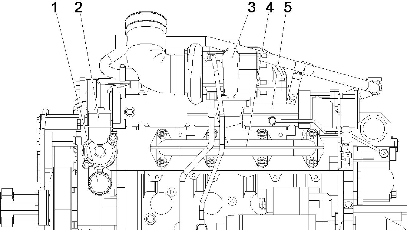
Alternator side view (step 1)
3
Engine, Alternator side view (step 1)
Alternator Engine lifting bracket
Coolant outlet
Coolant inlet
Fan pulley
Poly - V-pulley with vibration damper
Poly - V-belt tension pulley
Coolant pump
Fuel pump
Alternator side view (step 2)
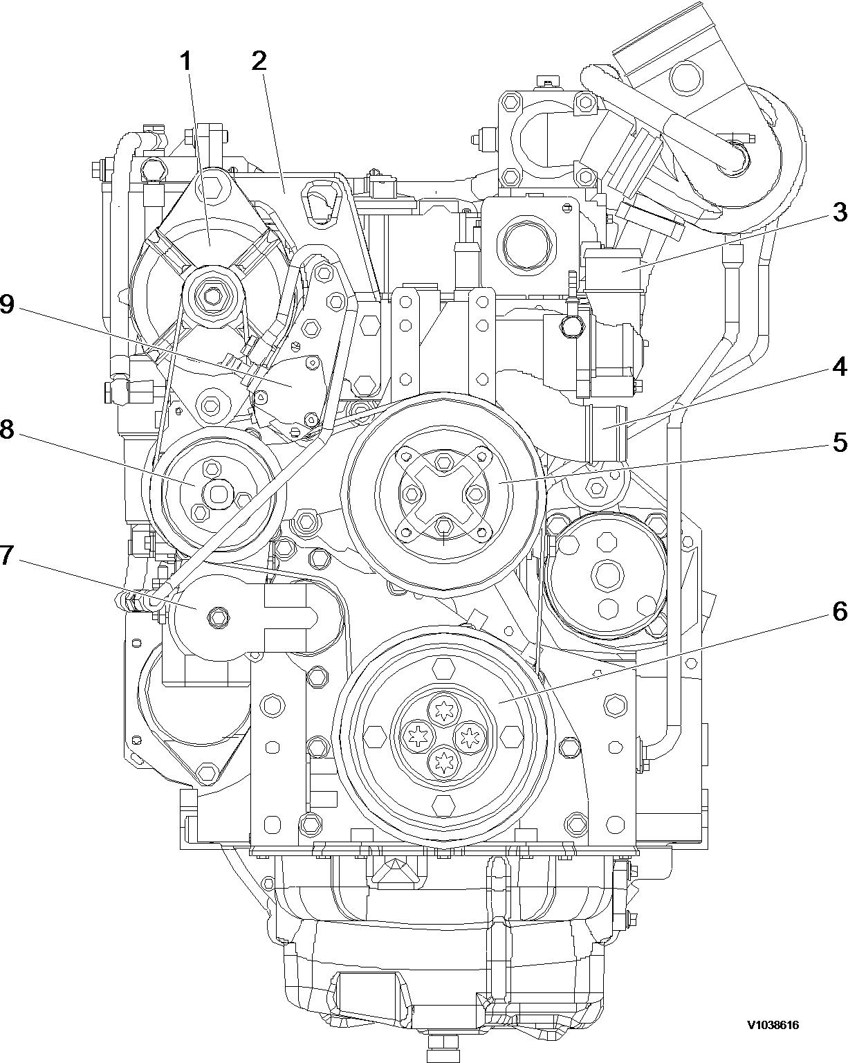
4
Engine, Alternator side view (step 2)
Alternator
Engine lifting bracket
Coolant outlet
Coolant inlet
Fan pulley
Poly - V-pulley with vibration damper
Poly - V-belt tension pulley
Coolant pump
Fuel pump
Top view (step 1)

Top view (step 2)

2)
Fuel filter side view (step 1)
Fuel filter side view (step 2)


9
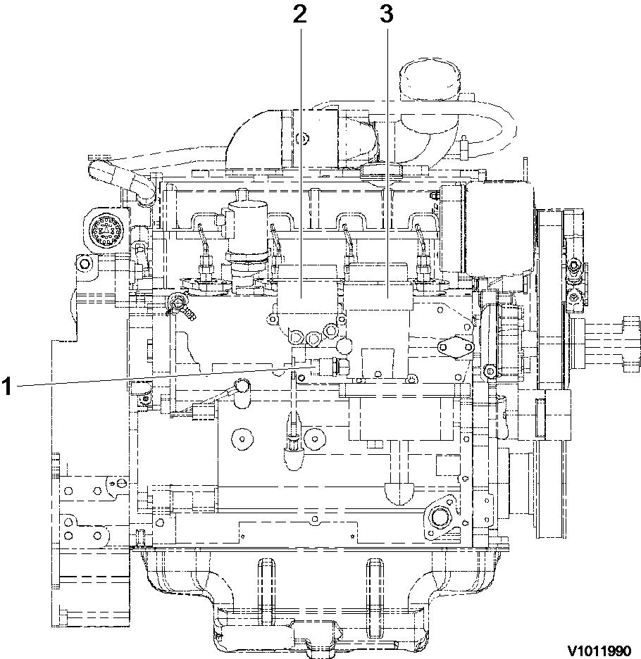
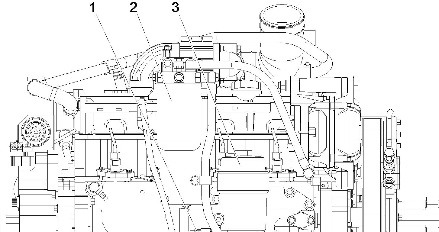
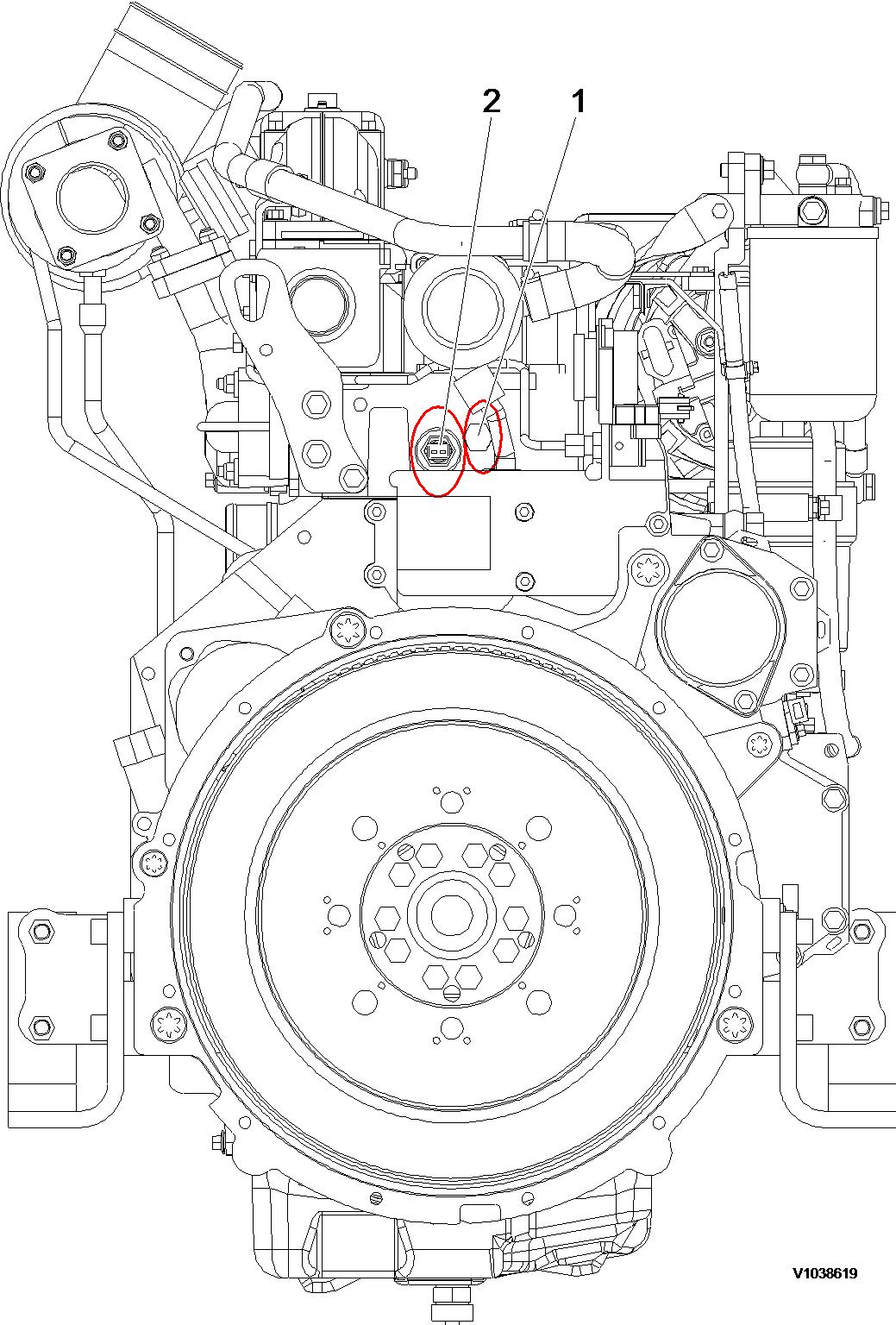
Engine, flywheel end view (step 1)
1. 2. Coolant temperature check port
Coolant temperature sensor port
Flywheel end view (step 2)
Document Title: Function Group: Information Type: Date:
Engine characteristic curve 210 Service Information 2015/3/4 0
Profile:
EXC, EC140B LCM [GB]
Engine characteristic curve
Engine characteristics
Item
Maximum power (Net)
Maximum torque (Net)
Minimum fuel consumption
Rated fuel consumption
Specification
94 PS (69 kW) / 2100 rpm
38 kgf·m (274 lbf·ft, 372 N·m) / 1500 rpm
157 g / PS·h
163 g / PS·h

Engine, characteristic curve
P Power
T Torque
FC Fuel consumption
S Speed
Document Title: Function Group: Information Type: Date:
Cylinder head, description 211 Service Information 2015/3/4 0
Profile:
EXC, EC140B LCM [GB]
Cylinder head, description
The cylinder head of the D4D engine is made of grey cast iron and designed as block type head. The combustion air enters vertically and the exhaust air is discharged laterally. Inlet and outlet are located on one side of the cylinder head.
Document Title: Function Group: Information Type: Date:
Determining cylinder head gasket 211 Service Information 2015/3/4 0
Profile:
EXC, EC140B LCM [GB]
Determining cylinder head gasket
The thickness of the cylinder head gasket is responsible for the correct piston crown clearance of the engine. The piston crown clearance (0.65 mm) essentially influences the combustion and thus:
Power Fuel consumption Exhaust emission
The piston crown clearance is adjusted by determining the piston projection and the thickness of the cylinder head gasket.
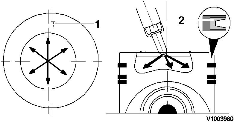
Measuring piston projection
A dial gauge with a fixture is needed to measure the piston projection. The piston is in its TDC position above the cylinder block face.
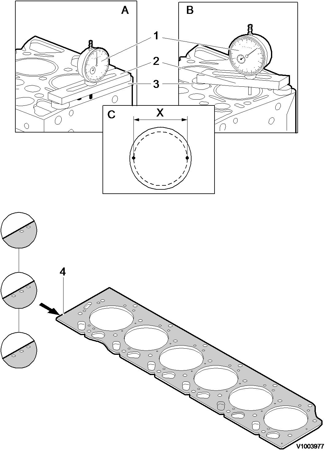
Figure 1
Measurement, piston projection
1. 2. 3. Dial gauge Bridge
Two spacer plates A. B. C.
Set the dial gauge on the level of the cylinder block face to "zero".
Position the dial gauge at measuring points (C), at the piston pin axis, on the piston and determine the maximum projection.
Measuring points on the piston.
Distance X = 90 mm
This measurement is performed on each piston. The maximum measured piston projection determines the thickness of the cylinder head gasket (see table). There are 3 different gasket thicknesses identified by bores (4):
1 bore = 1.2 mm
2 bores = 1.3 mm
3 bores = 1.4 mm
Piston projection
Piston projection Identification of cylinder head gasket
0.33 0.55 mm 1 bore
0.56 ~ 0.65 mm 2 bores
0.66 ~ 0.76 mm 3 bores
Document Title: Function Group: Information Type: Date:
Fitting cylinder head 211 Service Information 2015/3/4 0
Profile:
EXC, EC140B LCM [GB]
Fitting cylinder head
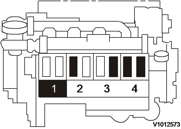
Op nbr 21182
1. Prior to fitting the cylinder head onto the crankcase, the sealing surfaces for the cylinder head gasket must be clean and free from oil. Pay attention to dowel sleeves.
2. Lightly oil the cylinder head bolts.
3. It is absolutely necessary to observe the bolt tightening order in the adjacent schematic.

Figure 1
Tightening order (exhaust manifold side)
Tightening torque specification:
1st step: 30 N·m (22.2 lbf·ft, 3.1 kgf·m)
2nd step: 80 N·m (59 lbf·ft, 8.2 kgf·m)
3rd step: 90° turn
Tightening order
Document Title: Function Group: Information Type: Date:
Cylinder, description 213 Service Information 2015/3/4 0
Profile:
EXC, EC140B LCM [GB]
Cylinder, description
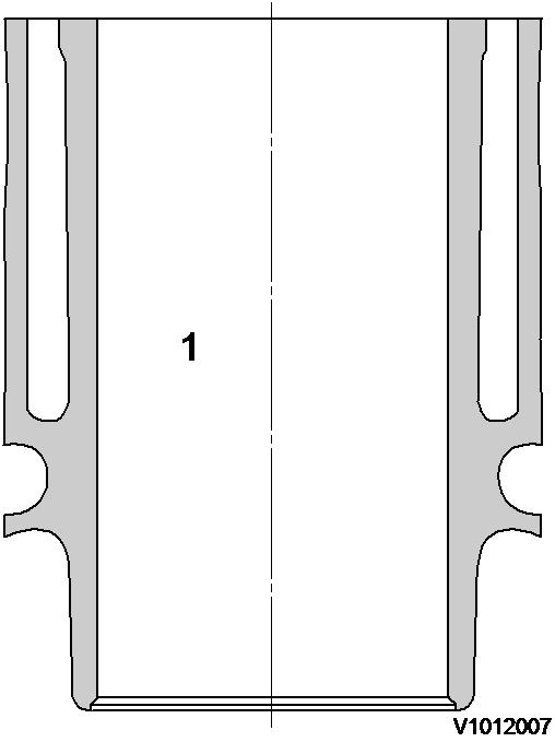
1
Cylinder liner
D4D engine with a bore about 101 mm (3.98 in) has a crankcase with integrated cylinder liners (1), i.e. crankcase and nonreplaceable liners form one casting.
Document Title: Function Group: Information Type: Date:
Pistons, description 213
Profile:
EXC, EC140B LCM [GB]
Pistons, description
Service Information 2015/3/4 0
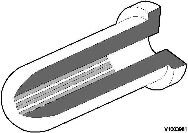
The pistons of the D4D engine are made of a special aluminium alloy. The piston bowl has a small amount of eccentricity to the piston axis.
The piston must be installed so that flywheel symbol (1) on the piston top faces the flywheel.
The pistons are equipped with 3 piston rings. The 1st ring has a ring carrier (2) of cast iron.
The cross section of the 1st piston ring is asymmetrical. The cross section of the 2nd piston ring is conical (compression ring). When installing the piston, the TOP mark at the ring gap must point upwards. The 3rd ring is the bevelled-edge oil control ring.
Document Title: Function Group: Information Type: Date: Piston cooling 213 Service Information 2015/3/4 0
Profile: EXC, EC140B LCM [GB]
Piston cooling
1
Piston cooling
The piston is cooled by spraying lube oil against the inside of the piston top.
The 2-hole piston cooling nozzles made of plastic are fitted in the main bearing pedestals.
Document Title: Function Group: Information Type: Date:
Valves, description 214
Profile:
EXC, EC140B LCM [GB]
Valves, description
Service Information 2015/3/4 0
The engine is provided with one inlet and one exhaust valve per cylinder. The valve guides are shrunk in the cylinder head. The valve seat inserts are made of high-quality steel and are also shrunk in the cylinder head. The valves are turned by eccentric actuation through the rocker arms. The new compressed cone connection permits easy turning of the valve despite stress load.
NOTE!
The valve springs of the D4D have a special installation direction. The colored mark on the spring must show to the bottom.
Rocker arm lubrication is integrated in the lube oil circuit. The oil is supplied via tappets and push rods.
Valve seat angle
Document Title: Function Group: Information Type: Date:
Valves, adjusting 214 Service Information 2015/3/4 0
Profile:
EXC, EC140B LCM [GB]
Valves,
adjusting
Op nbr 21412
The valve clearance must be checked and adjusted at specified intervals. To do this, the engine oil temperature must be between 20 °C (68 °F) and 80 °C (176 °F).
Valve clearance adjustment
Adjustment
1. Remove rocker cover.
1
Adjustment, valve clearance
2. Turn crankshaft until both valves in cylinder 1 overlap (exhaust valve about to close, inlet valve about to open).
3. Adjust clearance of valves marked in black in figure. Mark respective rocker arm with chalk to show that adjustment has been done.
4. Turn crankshaft one full revolution (360°). Now adjust clearance of valves marked black in figure.

2
Adjustment, valve clearance