
Document Title: Function Group: Information Type: Date: Engine, description 200 Service Information 2014/7/17
Profile: EXC, EW210C [GB]
Engine, description
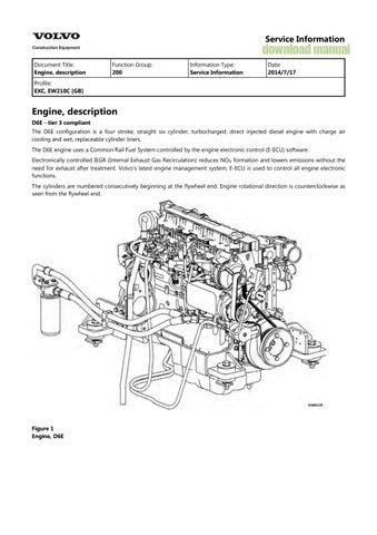
D6E - tier 3 compliant
The D6E configuration is a four stroke, straight six cylinder, turbocharged, direct injected diesel engine with charge air cooling and wet, replaceable cylinder liners.
The D6E engine uses a Common Rail Fuel System controlled by the engine electronic control (E-ECU) software.
Electronically controlled IEGR (Internal Exhaust Gas Recirculation) reduces NO formation and lowers emissions without the need for exhaust after treatment. Volvo's latest engine management system, E-ECU is used to control all engine electronic functions.
The cylinders are numbered consecutively beginning at the flywheel end. Engine rotational direction is counterclockwise as seen from the flywheel end.
Document Title: Function Group: Information Type: Date:
Engine, identification 200 Service Information 2014/7/17
Profile: EXC, EW210C [GB]
Engine, identification
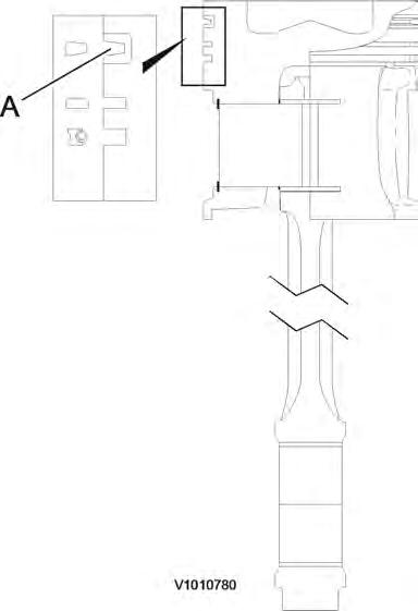
Identification plate
The engine model, serial number and performance data are stamped on an identification plate which is attached on the cylinder head cover. The engine model designation and serial number must be indicated when ordering spare parts.
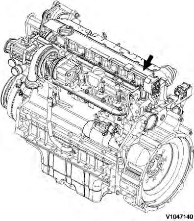
Engine identification, D6E
Document Title: Function Group:
EW210C [GB]
Component locations
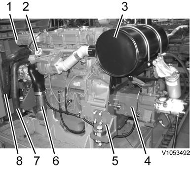
Component position, engine D6E. The following figures show the position of a number of components on engine D6E.
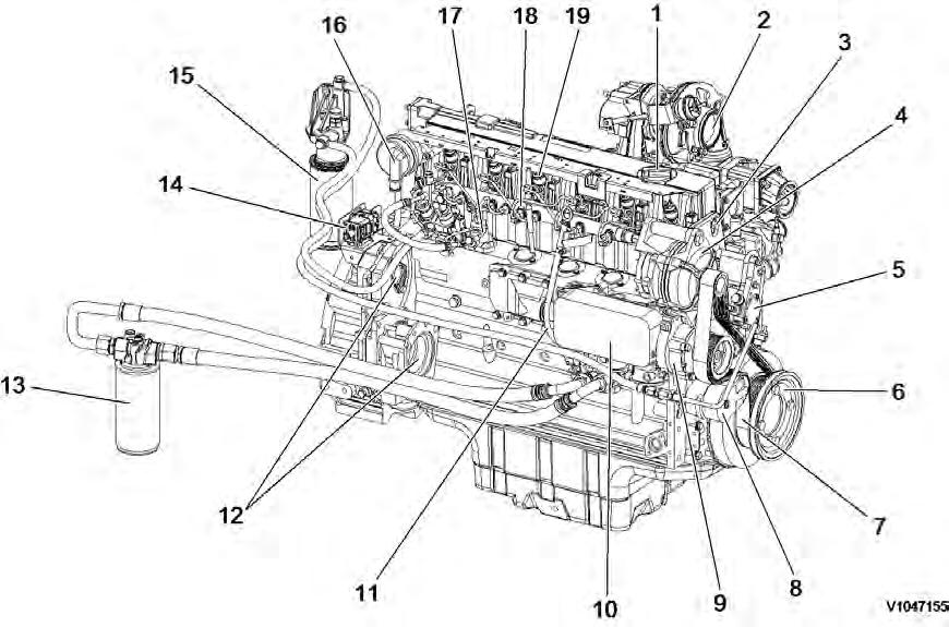

2 Component locations, flywheel side
21 Crankcase bleeding valve
22 Charge air manifold
23 Flywheel housing
Turbocharger
Coolant inlet
Air outlet (to charge air cooler) 24 Drain plug
Coolant outlet
25 Oil pan
Air inlet (from charge air cooler) 26 Starter motor
27 Oil return line from turbocharger
Exhaust manifold
Cylinder rocker arm cover
Document Title: Function Group: Information Type: Date: Engine, replacing 210 Service Information 2014/7/17
Profile: EXC, EW210C [GB]
Engine, replacing
Op nbr 210-076
9998547 Lifting tool

WARNING
Risk of burns - stop the diesel engine and allow it to cool down before starting any work.
WARNING
Hot oil and hot engine coolant can cause severe burns!
WARNING
The parts are heavy. Take appropriate safety cautions when handling them.
1. Engine removal Park the machine in service position B, see . 091 Service positions
2. Remove the counterweight, see 716 Counterweight, removing
3. Remove engine hood (1).
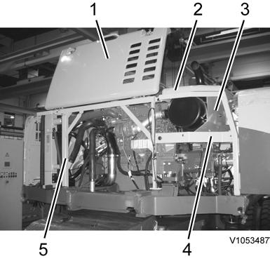
4. Remove silencer hood (2).
5. Remove silencer undercover (3).
6. Remove right side door frame with door (4).
7. Remove rear side frame (5).
8. Drain the hydraulic oil, see 173 Hydraulic system, changing oil
9. Drain the engine coolant, see 173 Coolant, change
10. Remove the coolant expansion tank, see 261 Expansion tank, replacing
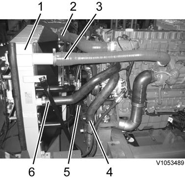
11. Disconnect charge air hoses (2 and 3), coolant hoses (4 and 6) and air inlet hose (5) from cooling unit (1) side.
NOTICE
Refrigerant under pressure. Do not disconnect any hoses or connections on the air conditioning, thereby involuntary releasing refrigerant.
Loosen belt tension adjusting nuts (2 and 3) and screw (1).

3
Air conditioner compressor
13. Remove air conditioner compressor belt (5).
14. Undo screws (6 and 7), and disconnect air conditioner compressor (4) from the engine.
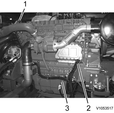
15. Unplug connector (1) for E-ECU and wire harness connector (5).
16. Disconnect hydraulic hoses (2 and 3) from the cooling fan pump. Plug open connections.
17. Disconnect coolant hose (4) from the engine oil cooler. Plug open connections.
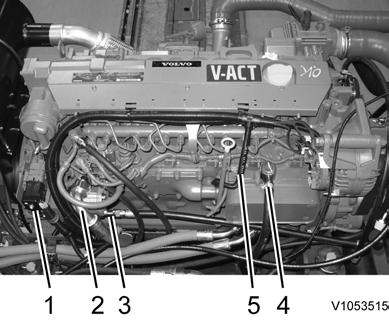
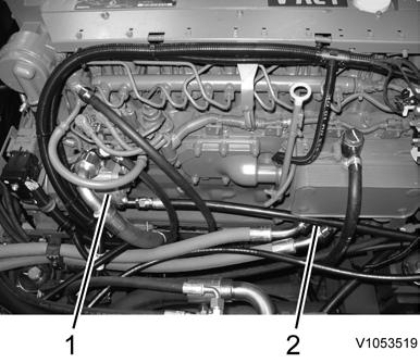
18. Disconnect fuel supply line (1) and return line (2). Plug open connections.
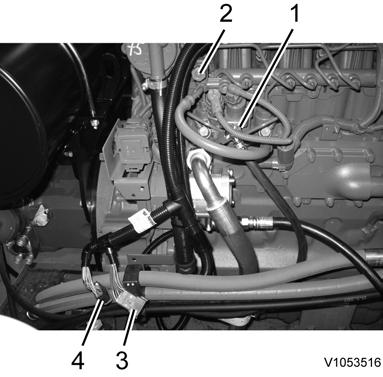
19. Disconnect wire harness connectors (3 and 4).
20. Disconnect air preheating cable (1), starter motor cable (2) and ground cable (3) from the engine.
21. Disconnect wire harness connector (1) and hydraulic hoses (2, 3, 4, 7, 8 and 9) from the hydraulic pump. Plug open connections.
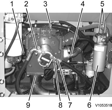
22. Loosen screws (5), and attach engine oil filter (6) to the hydraulic pump.
23. Remove the engine mounting screws, see 218 Engine mounting
24. Connect the lifting device 9998547 to the engine lifting eyes. Adjust the lifting device to the correct angle. Take up the slack in the lifting device
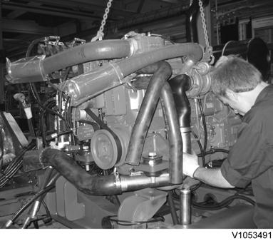
The parts are heavy. Take appropriate safety cautions when handling them.
25. Lift away the engine from the machine, and put it onto a suitable workbench.
Weight approx. 600 kg (1323 lbs)
26. Engine installation Move charge air hoses (1 and 2), coolant hoses (7 and 8) and air inlet hose (6) to new engine.
27. Remove silencer including the turbocharger flexible tune and the silencer bracket from the old engine. see , 252 Silencer, replacing 252 Exhaust pipe, flexible tube, replacing
28. Move hydraulic pump (4) including the pump coupling to new engine, see , 913 Pump, removal , , 913 Pump, installation 442 Pump coupling, removing 442 Pump coupling, installing
29. Move engine mounting brackets (5) at 4 places to new engine, see 218 Engine mounting
30. Move cooling fan pump (1) to new engine, see , 911 Cooling fan pump, removal 911 Cooling fan pump, installation
fan pump, moving
31. Move engine oil filter connection (2) to new engine.
32. Connect the lifting device 9998547 to the engine lifting eyes. Adjust the lifting device to the correct angle. Take up the slack in the lifting device
11
Engine, installation
WARNING
The parts are heavy. Take appropriate safety cautions when handling them.
33. Put the engine onto the machine carefully.
Weight approx. 600 kg (1323 lbs)
34. Tighten the engine mounting screws, see 218 Engine mounting
35. Connect wire harness connector (1) and hydraulic hoses (2, 3, 4, 7, 8 and 9) to the hydraulic pump, see 913 Pump, installation
12
Pump connections
36. Install engine oil filter (6) to the hydraulic tank.
37. Plug in connector (1) for E-ECU and wire harness connector (5).
Engine connections
38. Connect hydraulic hoses (2 and 3) to the cooling fan pump, see 911 Cooling fan pump, installation
39. Connect coolant hose (4) to the engine oil cooler.
40. Connect fuel supply line (1) and return line (2).
41. Connect wire harness connectors (3 and 4).
42. Connect air preheating cable (1), starter motor cable (2) and ground cable (3) to the engine.
43. Install the air conditioner compressor including the belt, see 874 Compressor, replacing incl draining and filling
44. Connect charge air hoses (2 and 3), coolant hoses (4 and 6) and air inlet hose (5) to cooling unit (1) side.
45. Install rear side frame (5).
Rear side frame, installation
46. Install right side door frame with door (4).
47. Install silencer undercover (3).
48. Install silencer hood (2).
49. Install engine hood (1).
50. Install the coolant expansion tank and fill the coolant, see 261 Expansion tank, replacing
51. Fill the hydraulic oil, see . 173 Hydraulic system, changing oil
52. Fill the engine oil, see . 173 Engine, oil and filter, change.
53. Bleed the fuel system, see 233 Fuel system, bleeding
The parts are heavy. Take appropriate safety cautions when handling them.
54. Install the counterweight, see 716 Counterweight, removing
55. Check the engine operation.
Document Title: Function Group: Information Type: Date:
Cylinder head, description 211 Service Information 2014/7/17
Profile: EXC, EW210C [GB]
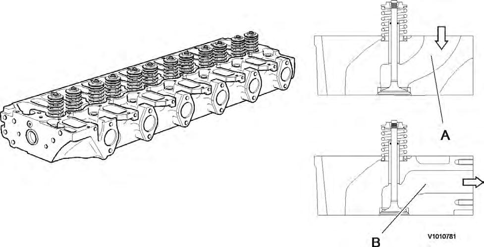
Cylinder head, description
The cylinder head is made of grey cast iron and is common for all cylinders. The induction air enters vertically (A) and the exhausts leave horizontally (B). Inlets and exhaust outlets are located on the same side of the cylinder block. Inlet and exhaust valve size is increased to optimize the gas exchange and combustion process. Valve guides are replaceable. Coolant flow in the cylinder head is modified to accommodate an outlet controlled cooling system. On order for the engine to fulfill governing emission standards, there are 3 cylinder head gaskets of different thicknesses between the cylinder head and the piston.
Document Title: Function Group: Information Type: Date:
Cylinder head gasket, description 211 Service Information 2014/7/17
Profile:
EXC, EW210C [GB]
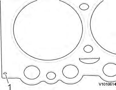
Cylinder head gasket, description
The cylinder head gasket is a multi layered gasket with 1, 2 or 3 identification holes to indicate three different thicknesses available. Selection of the proper thickness of gasket is determined by the measurement of piston projection above the cylinder block sealing surface. Recalibration for the correct gasket thickness would be required if new pistons or a new cylinder block were installed.
1
Document Title: Function Group: Information Type: Date:
Cylinder, description 213 Service Information 2014/7/17
Profile: EXC, EW210C [GB]
Cylinder, description

Figure 1
Cylinder liner
1 Cylinder liner
2 Crankcase
3 Liner projection: 0.07 - 0.12 mm
D6E engine with a bore about 98 mm (3.86 in) is provided with dry, plateau-honed slip-fit cylinder liners. In case of damage, the cylinders of the D6E series are repaired by replacing the slip-fit liners.
Document Title: Function Group: Information Type: Date:
Pistons, description 213 Service Information 2014/7/17
Profile:
EXC, EW210C [GB]
Pistons, description
D6E Engine
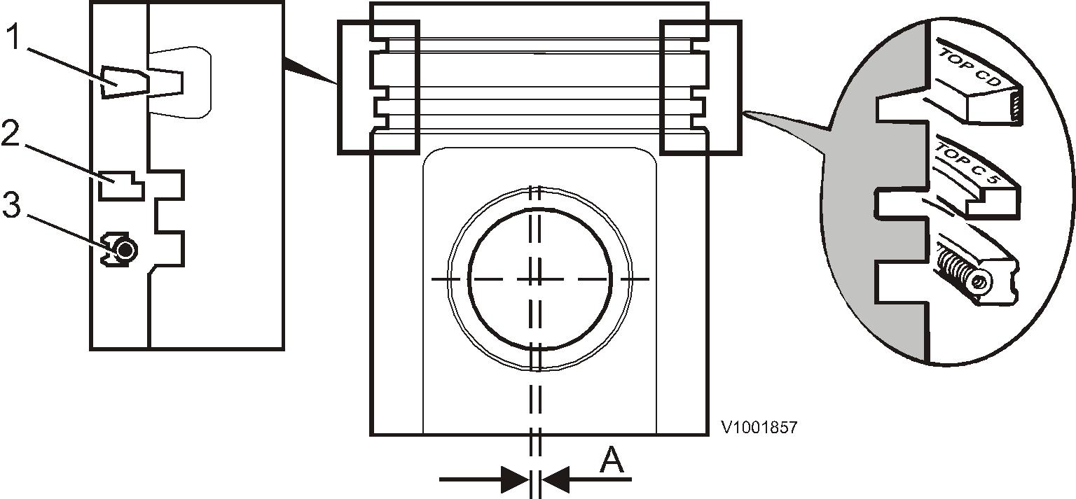
The pistons are made of special alloy aluminium. The piston's combustion compartment has a somewhat off-center (eccentric) position in relation to the piston pin.
The pistons are provided with 3 piston rings. The first ring has a ring carrier made of cast iron. The piston is cooled with oil sprayed up on the inside of the piston top.
The piston cooling nozzles are made of plastic and are mounted in the cylinder head by the main bearing positions.
The first piston ring has an asymmetric cross-section area (A). The cross-section area for piston ring number two (compression ring) is tapered. When installing the piston rings, the marking TOP by the opening in the rings must face up. The third ring is an oil ring with bevelled edge.

Suggest:
If the above button click is invalid.
Please download this document first, and then click the above link to download the complete manual.
Thank you so much for reading
Document Title: Function Group: Information Type: Date: Piston rings, description 213 Service Information 2014/7/17
Profile: EXC, EW210C [GB]
Piston rings, description
Each piston is equipped with two compression rings and one oil ring. The uppermost compression ring is of the "Keystone" type (dual trapezoid-formed cross section). Compressions rings should be placed with the text facing upwards. The oil ring is equipped with two scraping edges, which are pressed against the cylinder wall using the spring tension in the ring and an expander spring placed on the inside of the ring. The oil ring can be placed on either side but should be placed with expander spring and oil ring openings 180° from one another.