
Mega 400-V
Shop Manual
023-00040E
Serial Number 1001 and Up February 2001
Daewoo reserves the right to improve our products in a continuing process to provide the best possible product to the market place. These improvements can be implemented at any time with no obligation to change materials on previously sold products. It is recommended that consumers periodically contact their distributors for recent documentation on purchased equipment.
This documentation may include attachments and optional equipment that is not available in your machine’s package. Please call your distributor for additional items that you may require.
Illustrations used throughout this manual are used only as a representation of the actual piece of equipment, and may vary from the actual item.
023-00040E Shop Manual
Return to Master Table of Contents Safety
1TABLE OF CONTENTS
Main Pump (Denison T6DMY Series).................................................S0708460K
Steering and Brake Pump (Denison T67DB Siries)............................S0708470K
Brake Pedal Valve..............................................................................S0709230K
Main Control Valve (Toshiba).............................................................S0709455K
Pilot Control Valve..............................................................................S0709475K
Flow Amplifier (Danfoss).....................................................................S0709665K
Power Steering Unit............................................................................S0709730K
Unloader Valve...................................................................................S0709850K
Hydraulic Schematic (Mega 400-V)....................................................S0793050K
Electrical System
Electrical System................................................................................S0802180K
Electrical Schematic (Mega 400-V)....................................................S0893050K
Attachments
Table of Contents
2
TRANSMISSION DISASSEMBLY
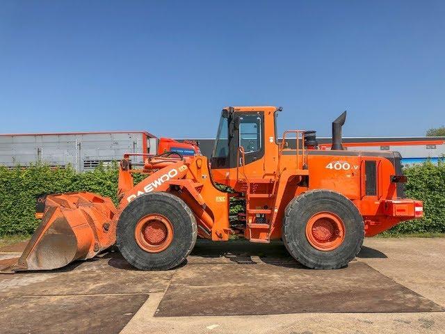
1.Fasten transmission on an appropriate support stand.
2.Disassemble complete shift control, remove pressure lines and duct plate.
CONVERTER-INPUT
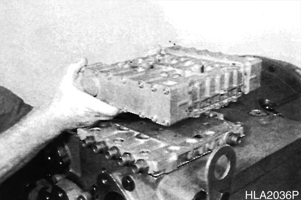
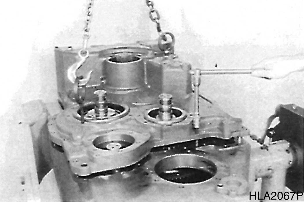
1.Separate torque converter from transmission, using lifting device.
S0607070K
Transmission and Torque Converter (ZF)
Figure 71
Figure 72
Figure 73
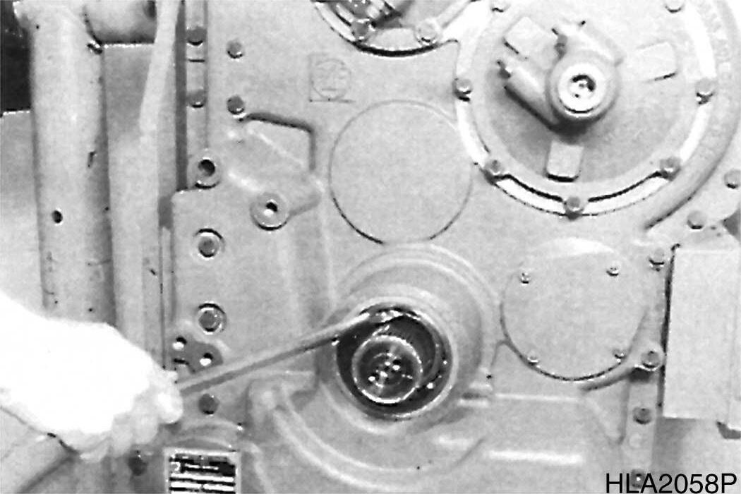
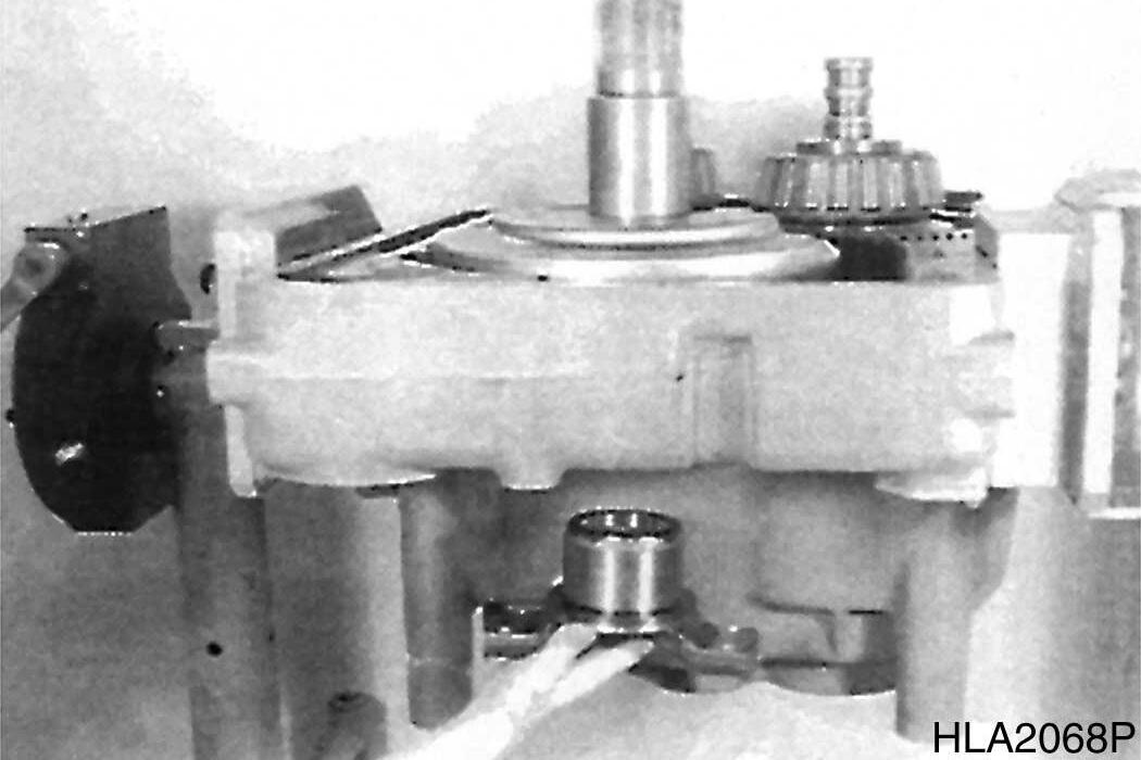
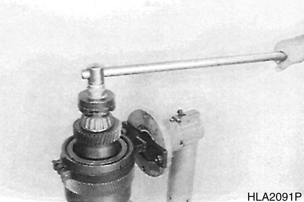
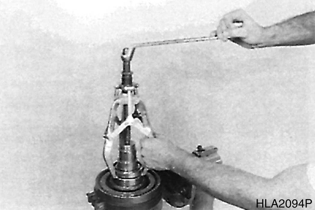
2.Loosen screw connection.
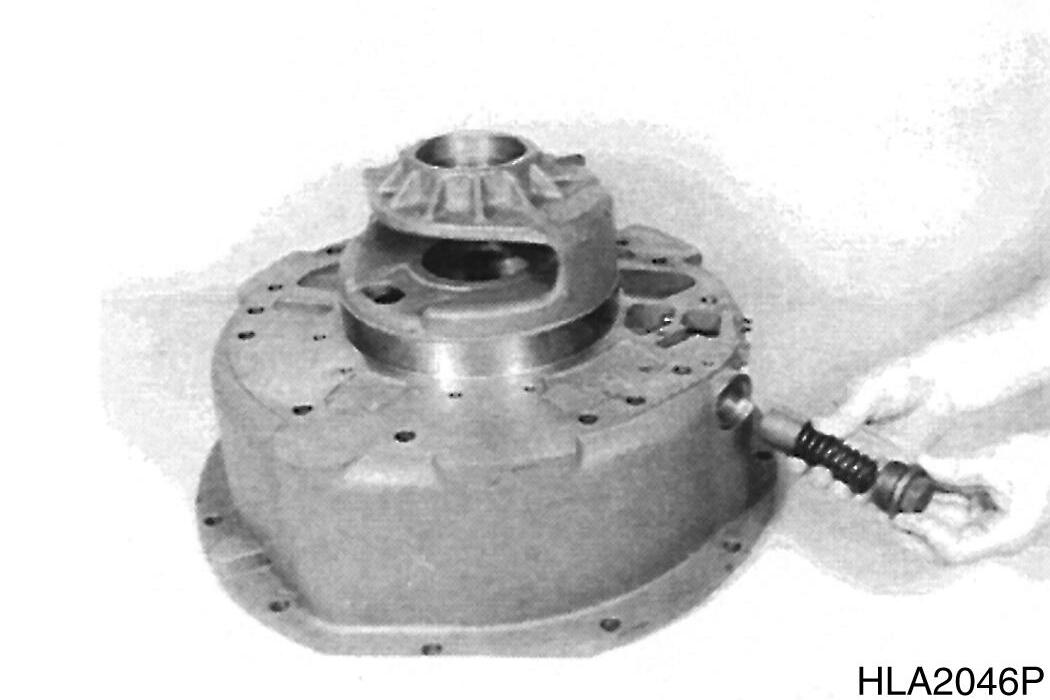
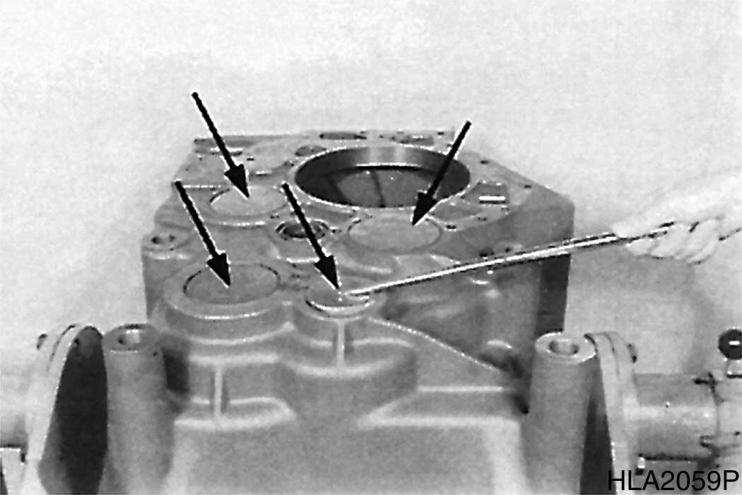
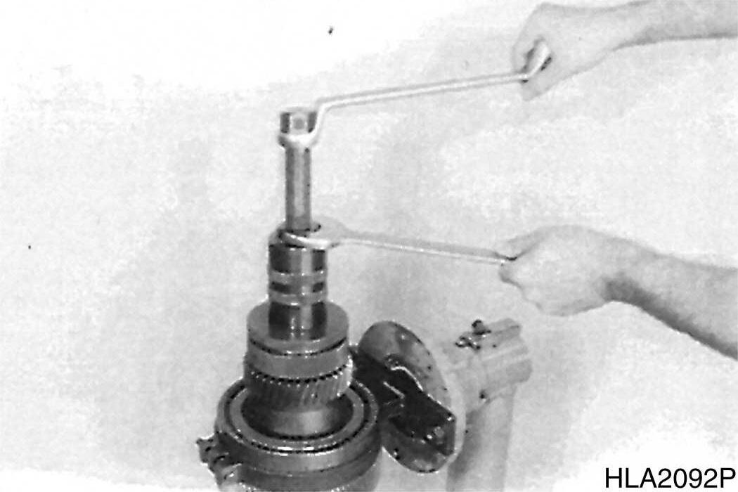
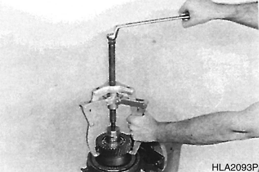
3.Separate bearing cover from converter bell, using three jacking screws.
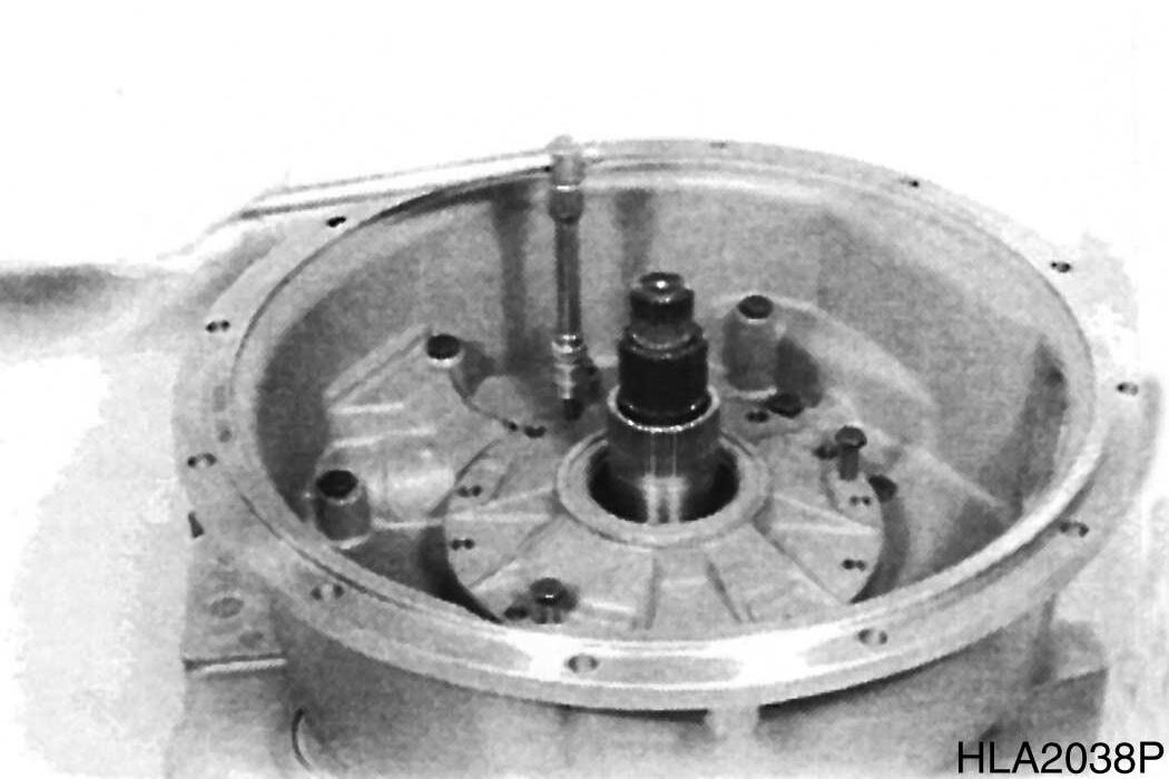
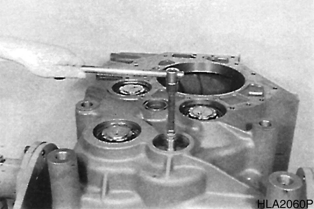
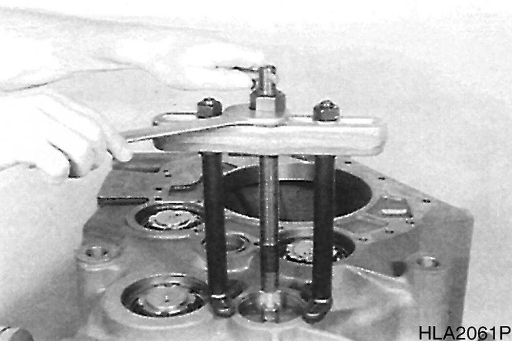
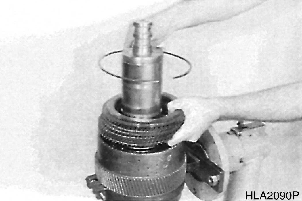
4.Pull oil feed flange out of converter bell, using special device (S).
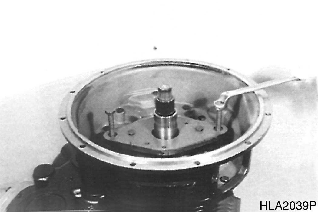
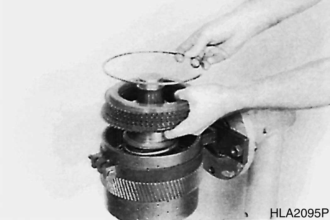
5.Remove converter safety valve (composed of ball, spring and disk.).
76
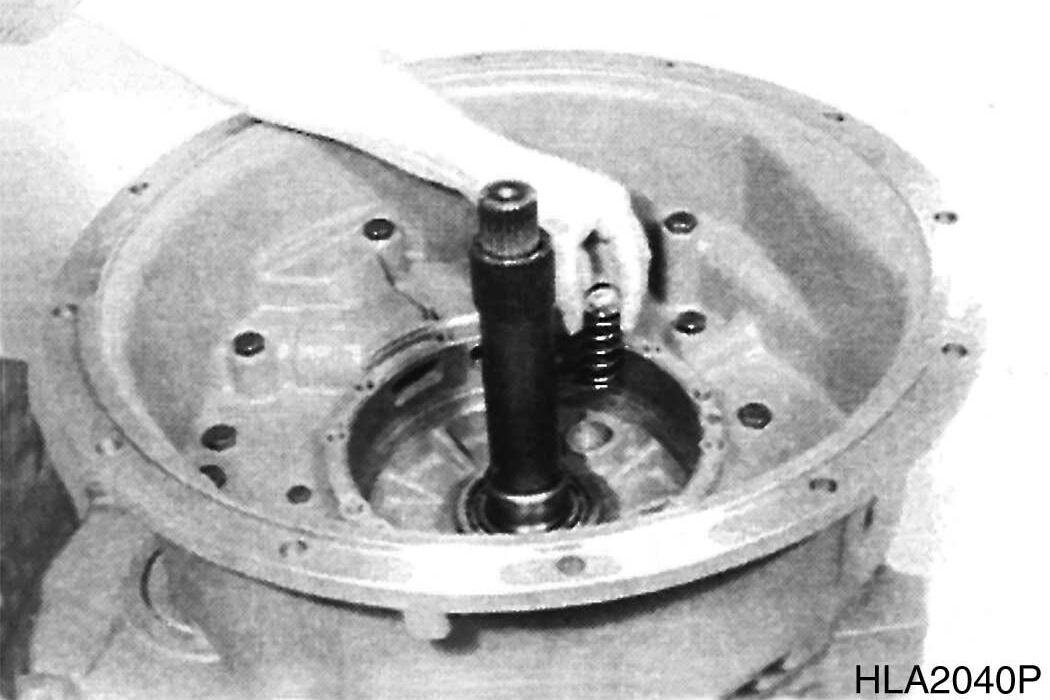
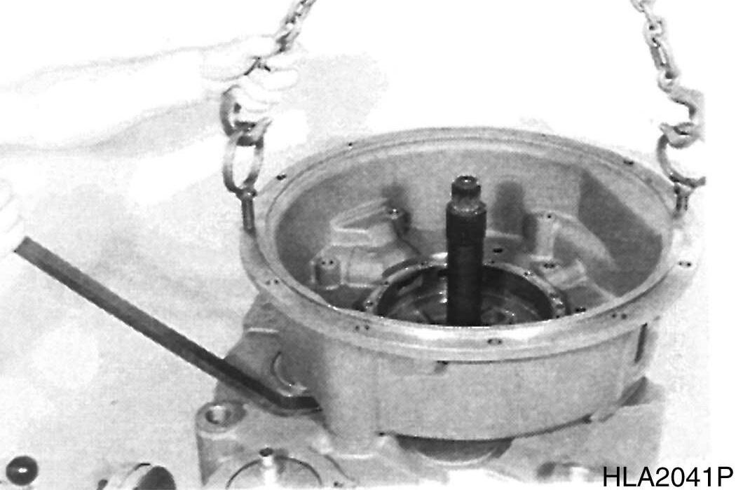
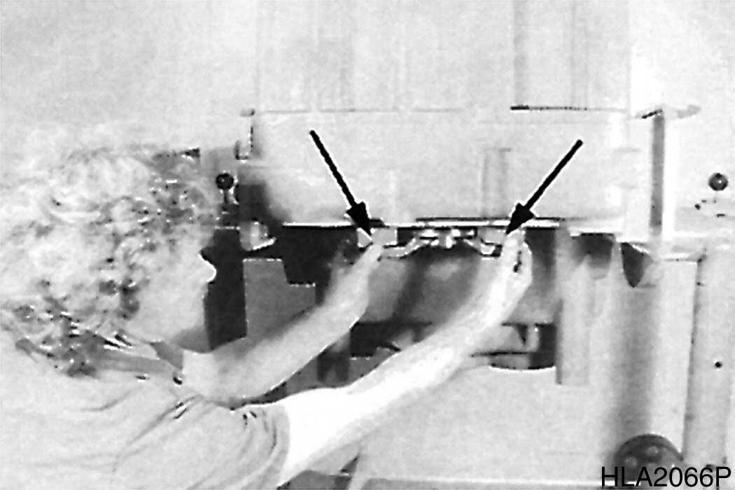
6.Separate converter bell from gearbox housing, using lifting device and pry bar.
Transmission and Torque Converter (ZF)
Figure 74
Figure 75
Figure
Figure 77
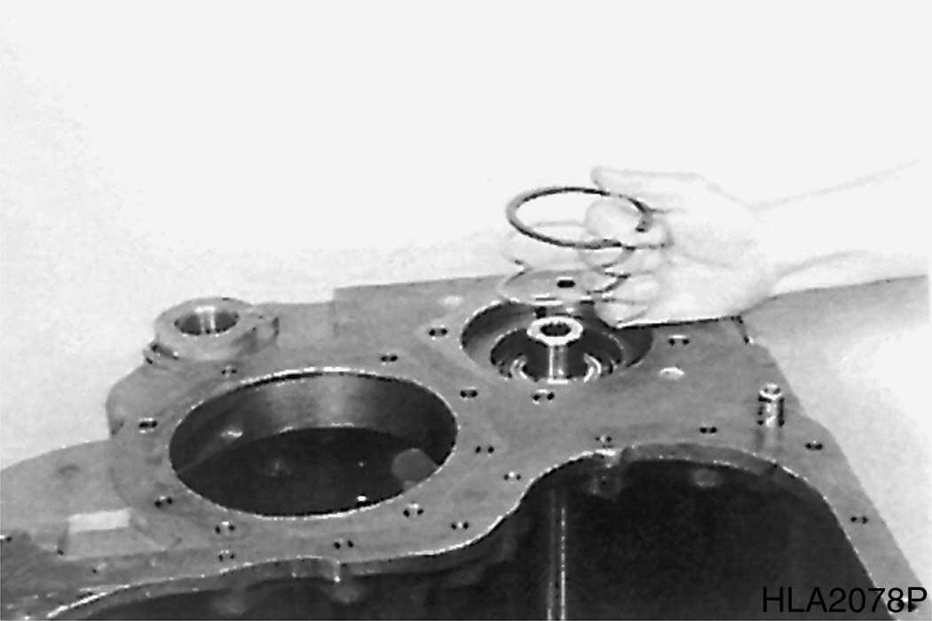
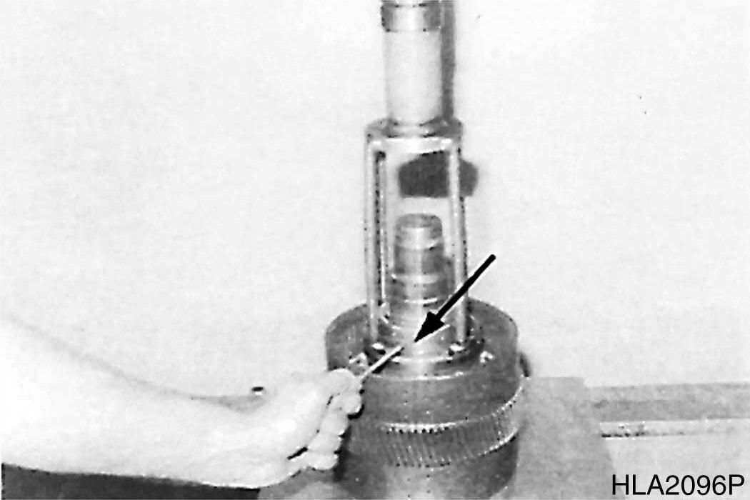
7.Remove shim.
8.Remove rectangular ring (Figure 79).
78
79
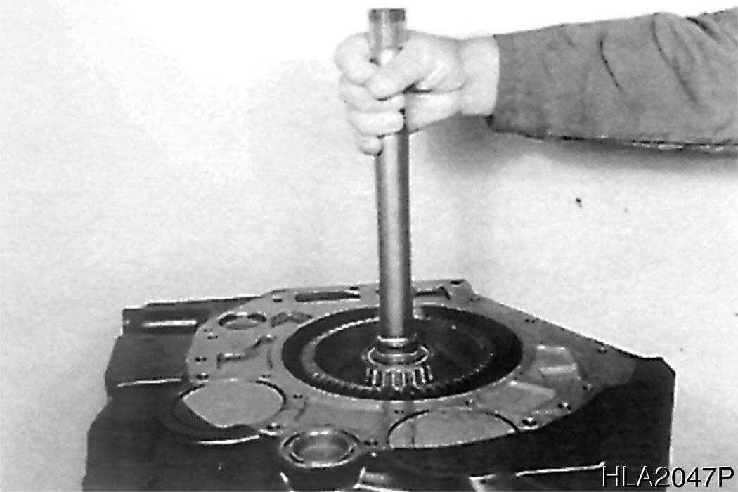
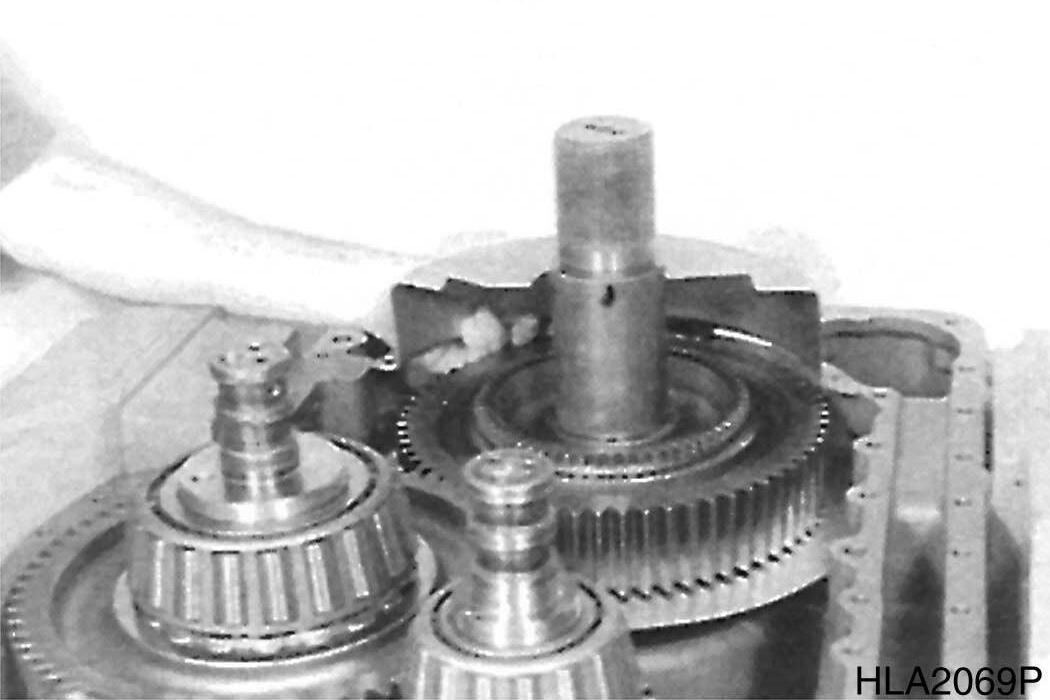
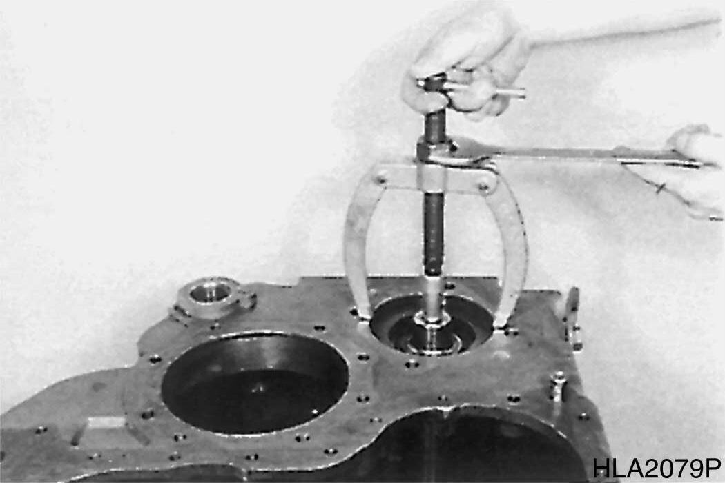
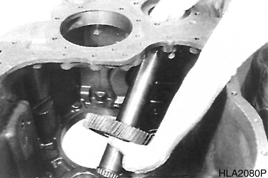
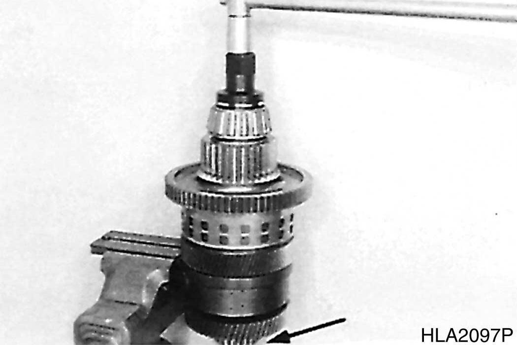
9.Press drive shaft out of spur gear bearing. Remove released inner bearing race and spur gear.
10.If necessary, drive outer bearing race out of housing bores.
80
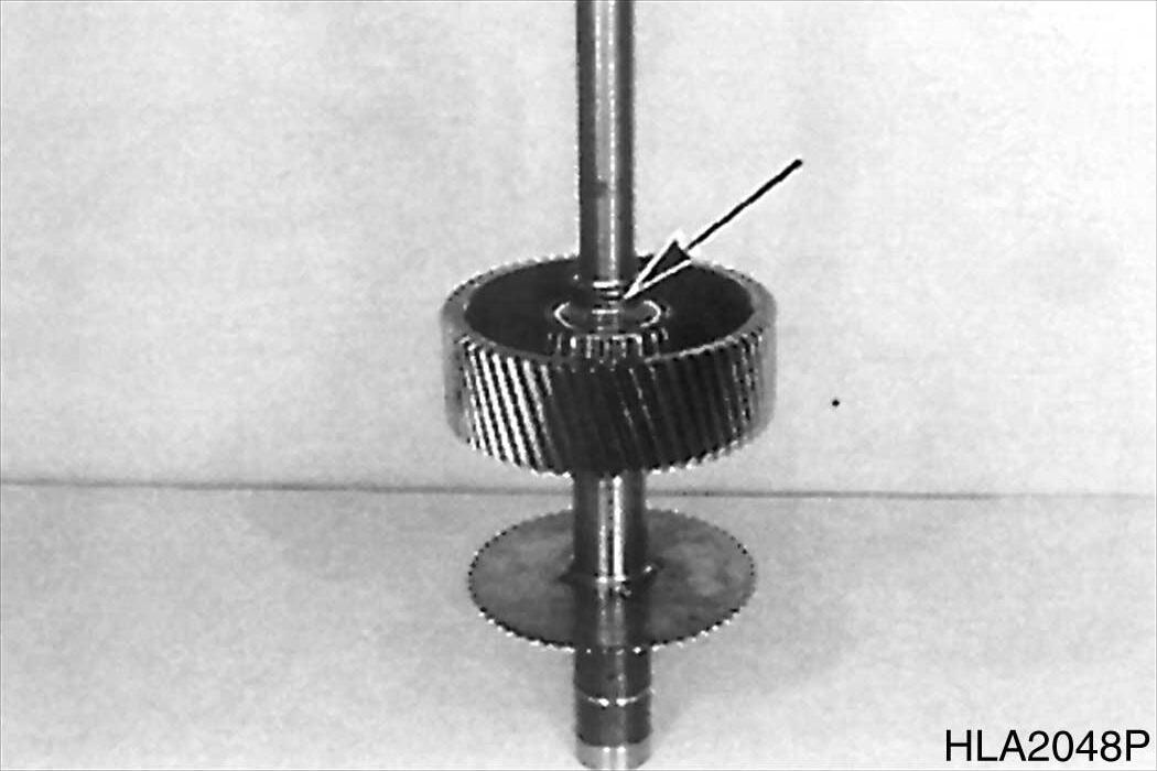
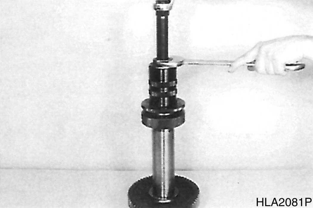
11.Press inner bearing race from drive shaft.
81
S0607070K
52 Transmission and Torque Converter (ZF)
Figure
Figure
Figure
Figure
12.Remove converter pressure valve.
82
DRIVE SHAFT PUMP POWER TAKE-OFF
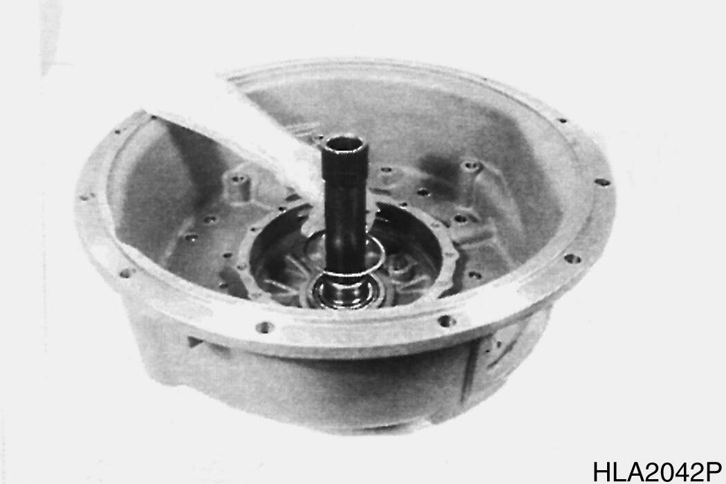
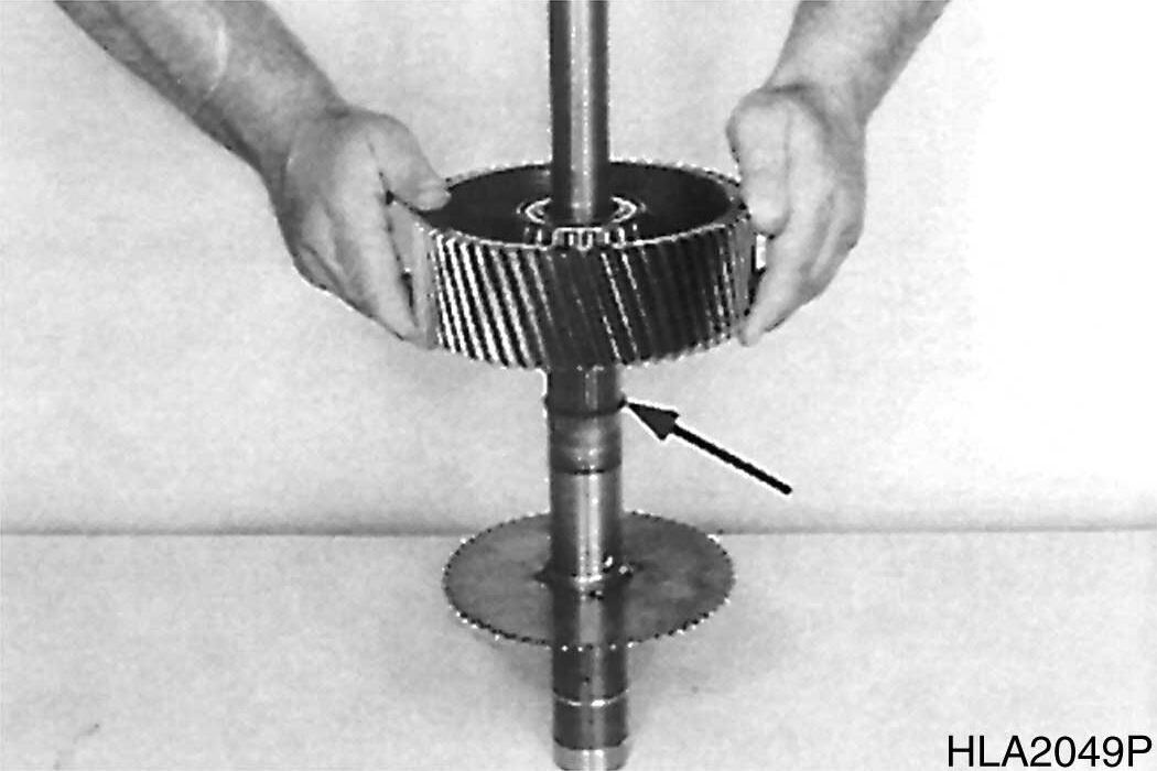
1.Pull complete drive shaft out of gearbox housing (pump).
83
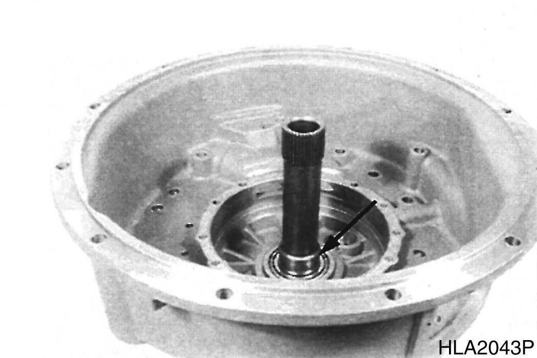
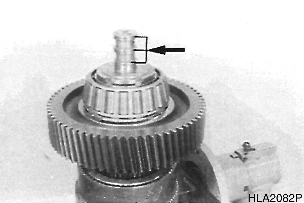
2.Remove rectangular ring (Figure 84).
84
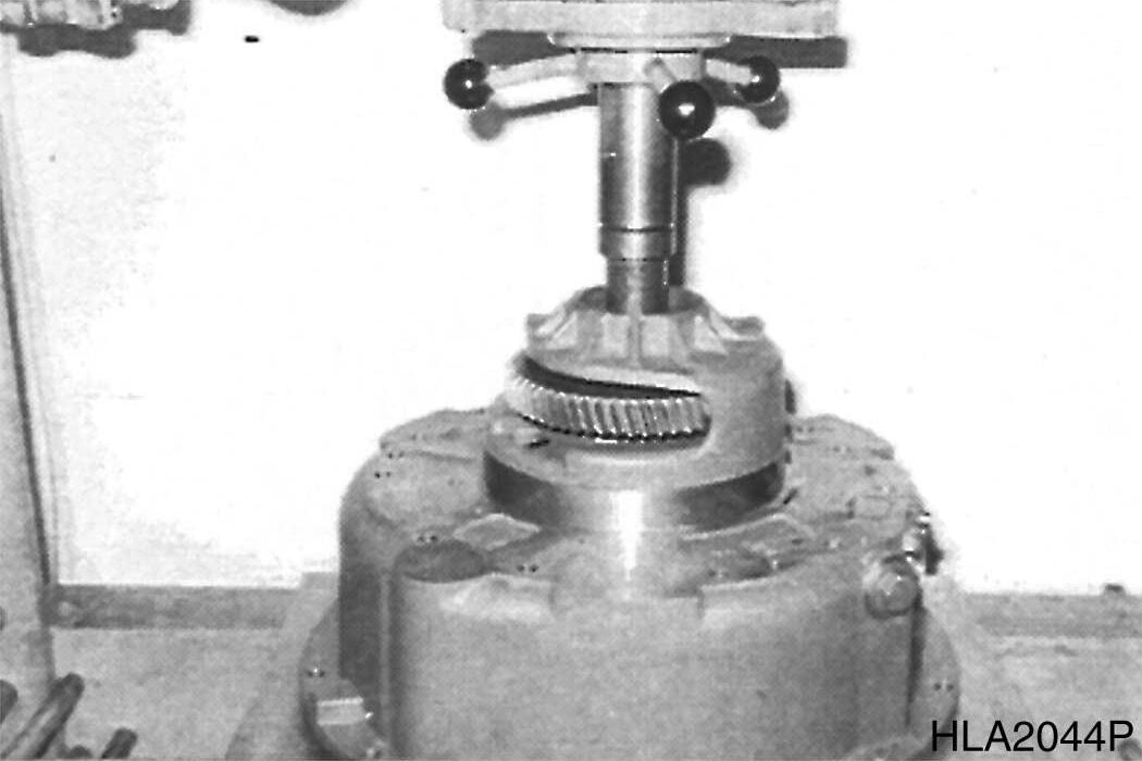
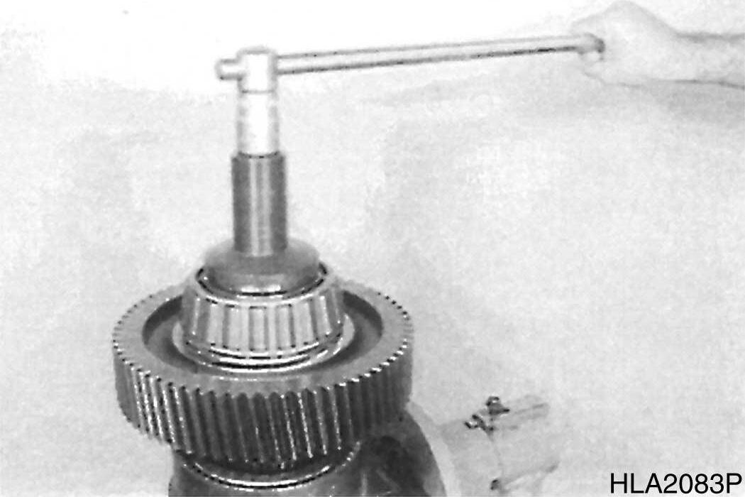
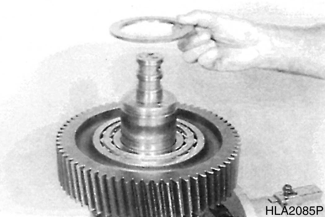
3.Separate spur gear from shaft and remove snap ring (Figure 85).
85
Transmission and Torque Converter (ZF)
Figure
Figure
Figure
Figure
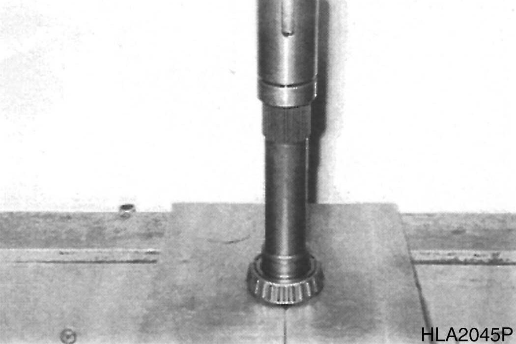
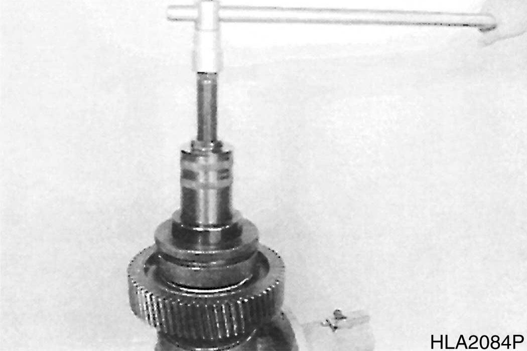
4.Pull inner bearing race from spur gear.
86
5.Loosen socket head screw and remove it along with clamping plate.
87
6.Pull inner bearing race and drive from shaft.
NOTE: Support puller on end face/ drive shaft. Pay attention to released shims.
7.Separate inner bearing race from driver.
NOTE: Pay attention to released shim.
8.Remove snap rings (3x).
88
89
S0607070K
54 Transmission and Torque Converter (ZF)
Figure
Figure
Figure
Figure
TRANSMISSION PUMP
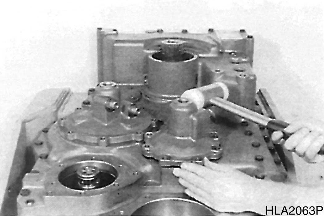
1.Tilt gearbox housing 180°
2.Loosen hex. head screws and remove both pump flanges.
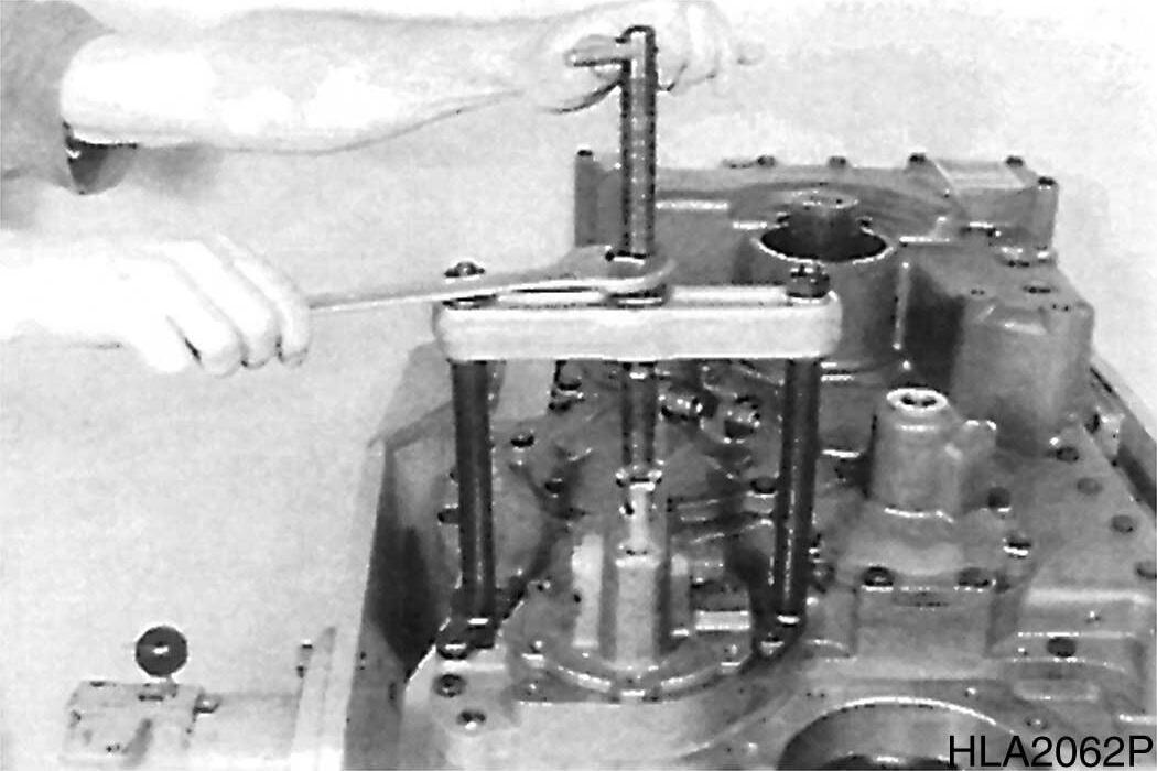
3.Loosen socket head screws (M8) and position Puller device (s).
4.Pull transmission pump out of housing bore.
NOTE: Tapping housing face is a help during extraction operation.
OUTPUT- LAYSHAFT ASSEMBLY
1.Loosen screw connection and remove brake caliper.
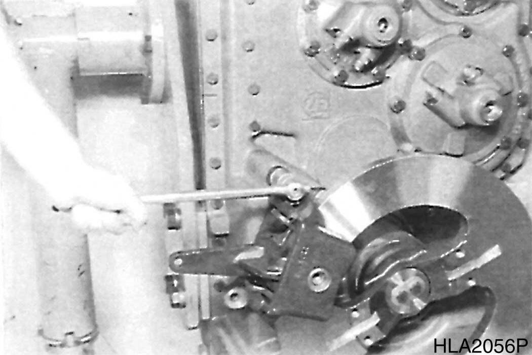
2.Unlock and loosen hex. head screws, tap brake disk loose and separate it from output shaft.
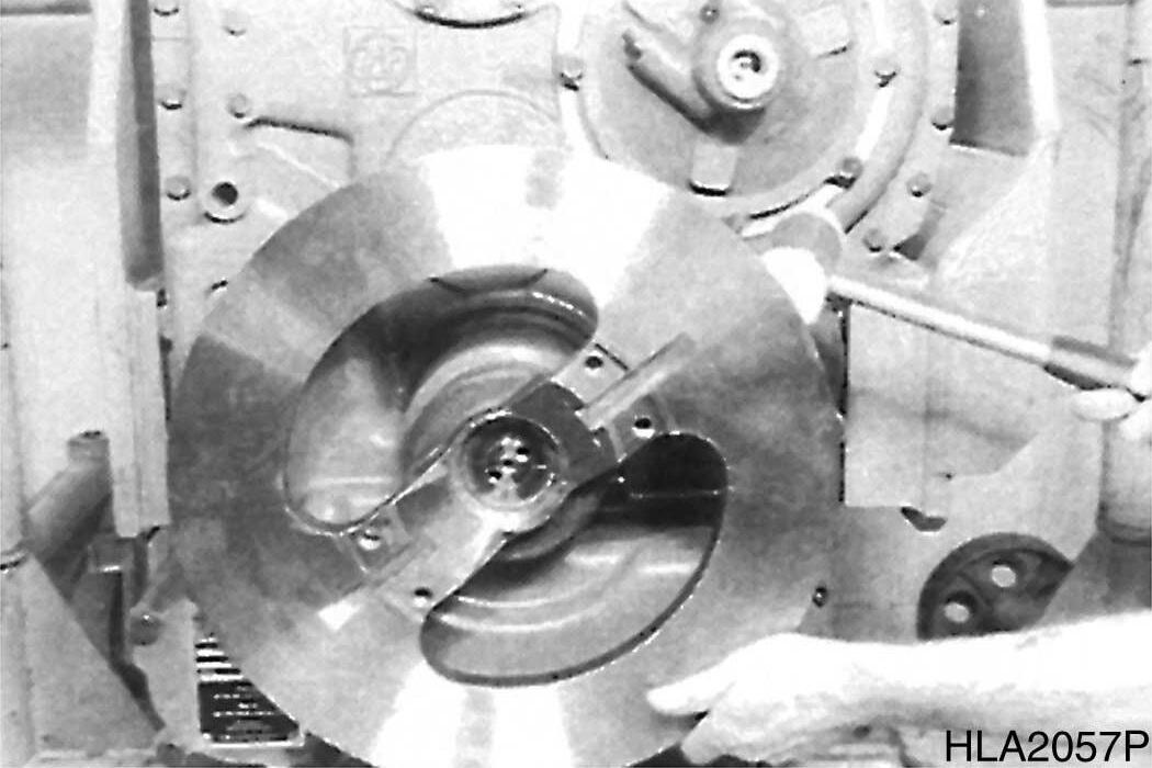
Figure 90
Figure 91
Figure 92
Figure 93
3.Pry shaft seal out of housing bore.
4.Tilt gearbox housing.
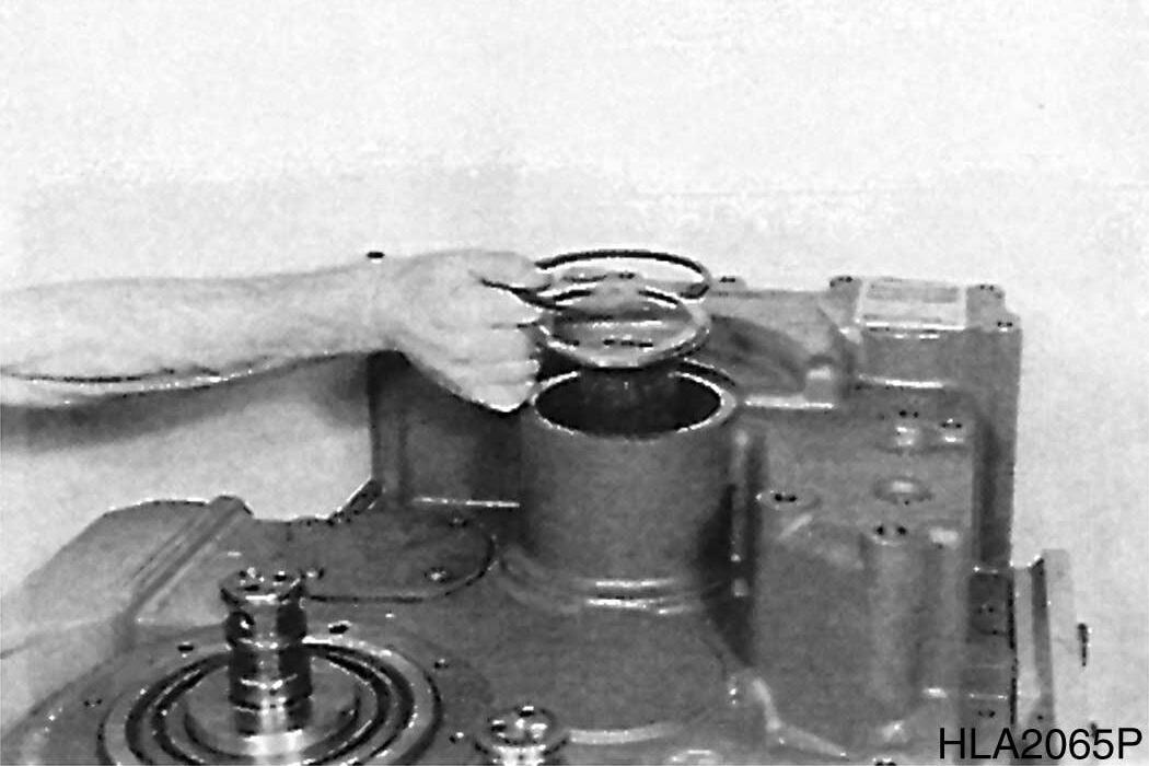
5.Remove sealing covers (Figure 95).
95
6.Loosen hex. head screws.
S0607070K
56 Transmission and Torque Converter (ZF)
7.Pull idler shaft by means of puller out of housing bore.
Figure 94
Figure
Figure 96
Figure 97
8.Tilt gearbox housing 180°
9.Loosen hex. head screws and pull bearing cover -K1/KV out of housing bore.
98
10.Loosen hex. head screws and remove bearing cover KR/K2 and K3/K4.
99
11.Remove rectangular rings (3 pieces/axle), see Figure 100.
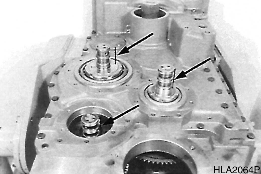
100
12.Remove snap ring and remove released washers.
101
Transmission and Torque Converter (ZF)
Figure
Figure
Figure
Figure
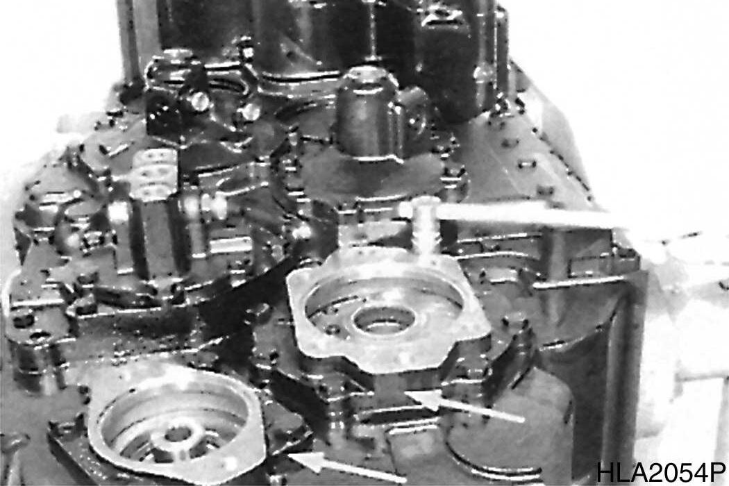
13.Support output flange against gearbox housing, see Figure 102.
14.Loosen hex. head screws and separate housing cover from gearbox housing, using forcing screws and lifting device.
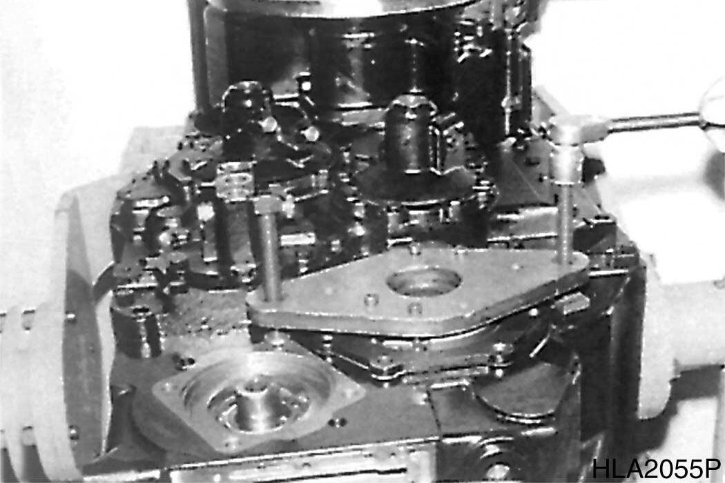
15.Unlock and loosen hex. head screws.
16.Remove output flange and pry shaft seal out of housing.
S0607070K
(ZF)
17.Loosen hex. head screws and remove oil baffle.
Figure 102
Figure 103
Figure 104
Figure 105
18.Remove output gear along with shaft.
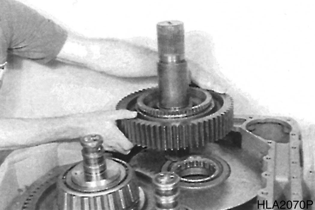
106
19.Separate output shaft from spur gear.
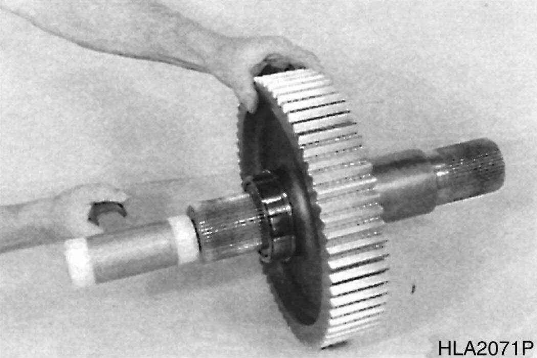
107
20.Pull inner bearing race from output gear.
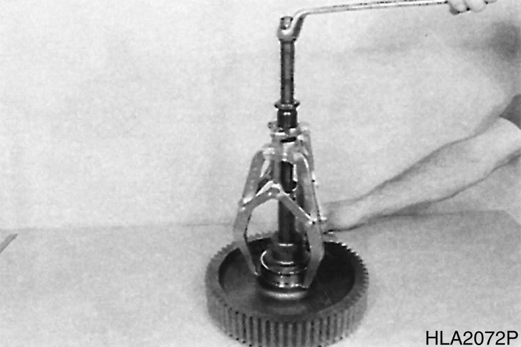
108
21.Remove plate.
Transmission and Torque Converter (ZF)
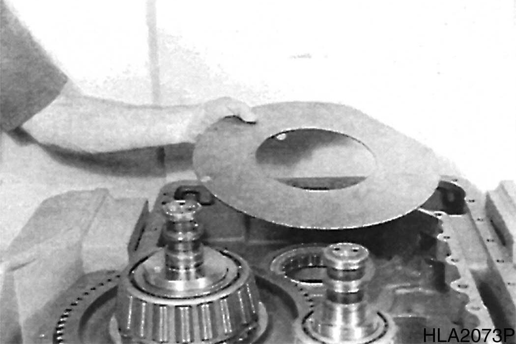
109
Figure
Figure
Figure
Figure
22.Drive roller bearing out of housing bore and remove it.
DISASSEMBLE CLUTCHES AND LAYSHAFT GEAR
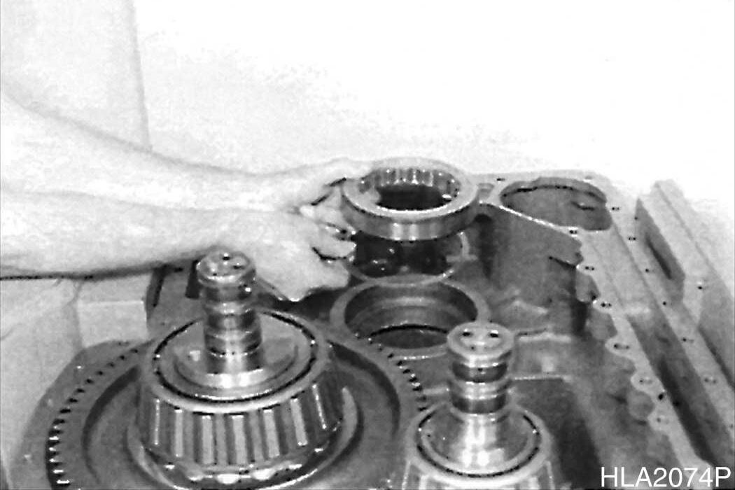
1.Remove clutches - K3/K4, KR/K2 and KV/ K1- by means of lifting device.
NOTE: At the removal of the clutchK3/K4, displace clutch - KR/K2 in direction of arrow (Figure 111).
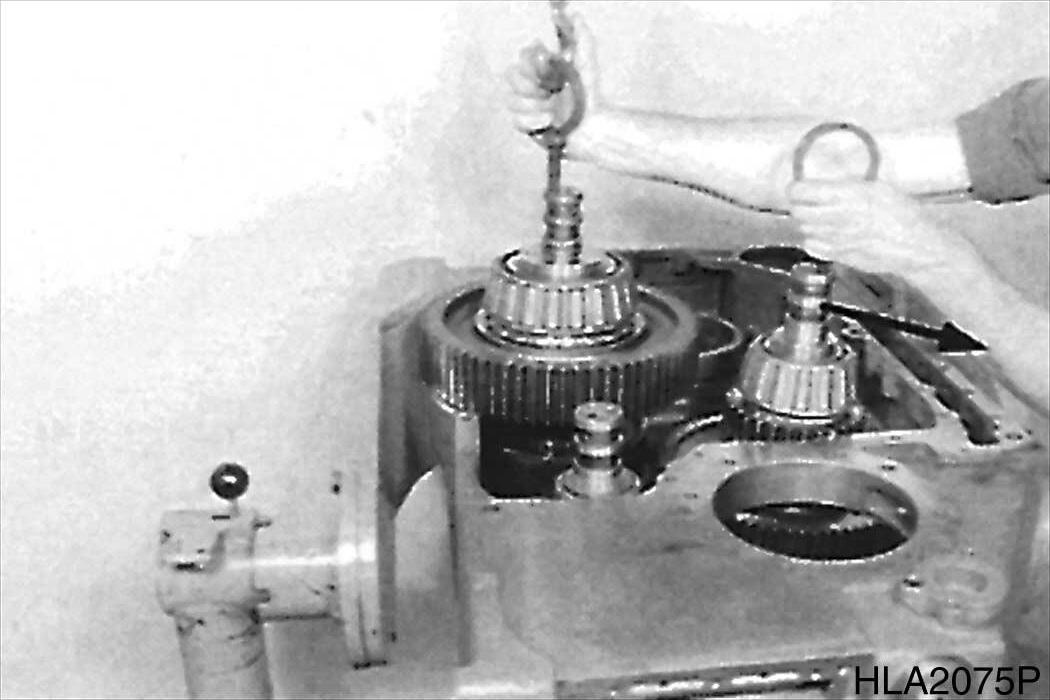
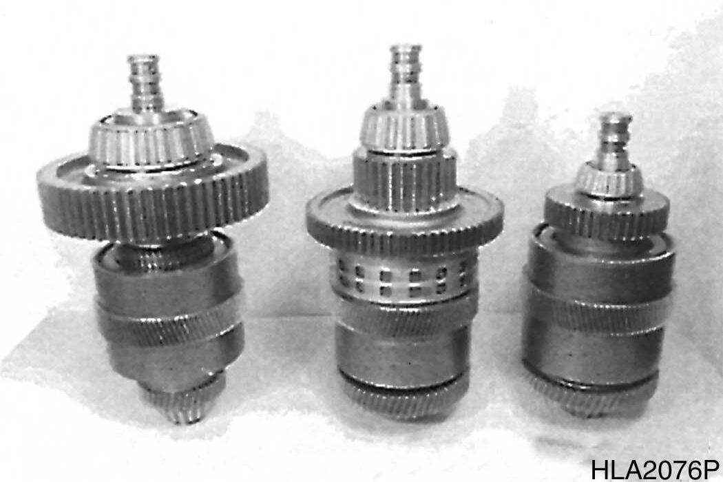
2.Illustration on right shows clutches in removed condition.
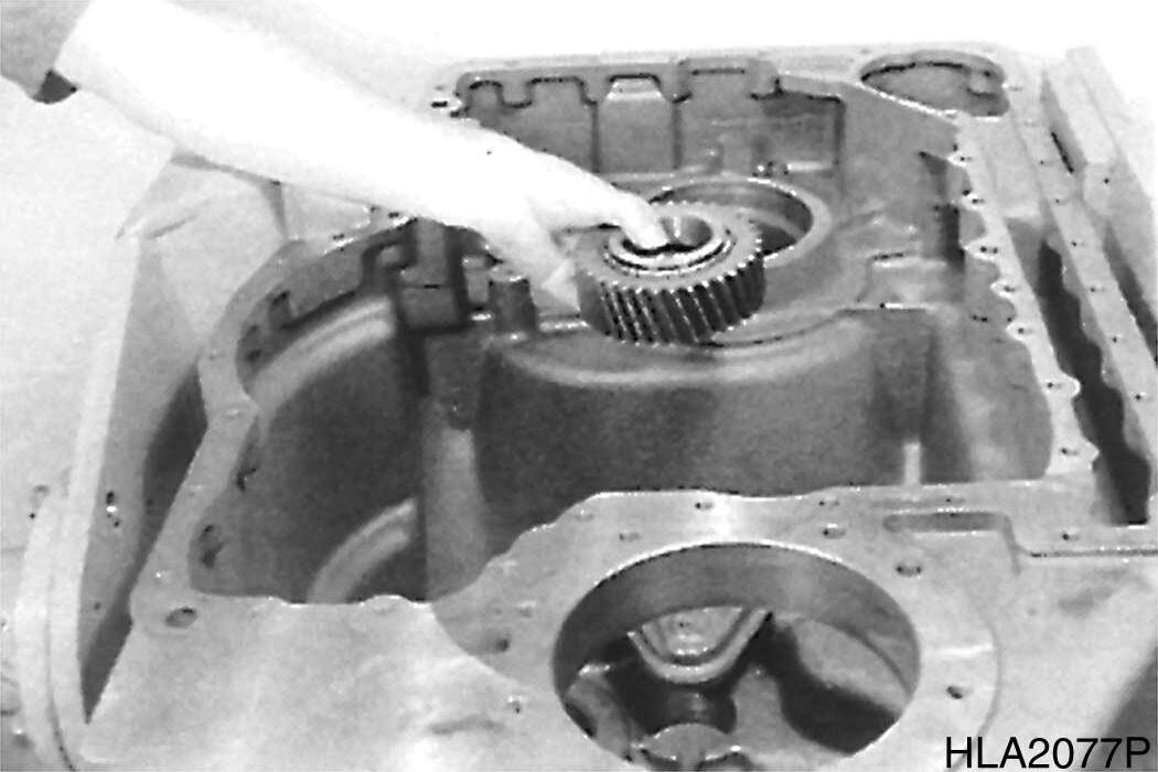
3.Remove layshaft gear.
S0607070K
Transmission and Torque Converter (ZF)
Figure 110
Figure 111
Figure 112
Figure 113
DISASSEMBLE POWER TAKE-OFF II
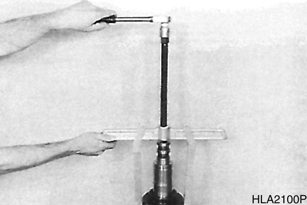
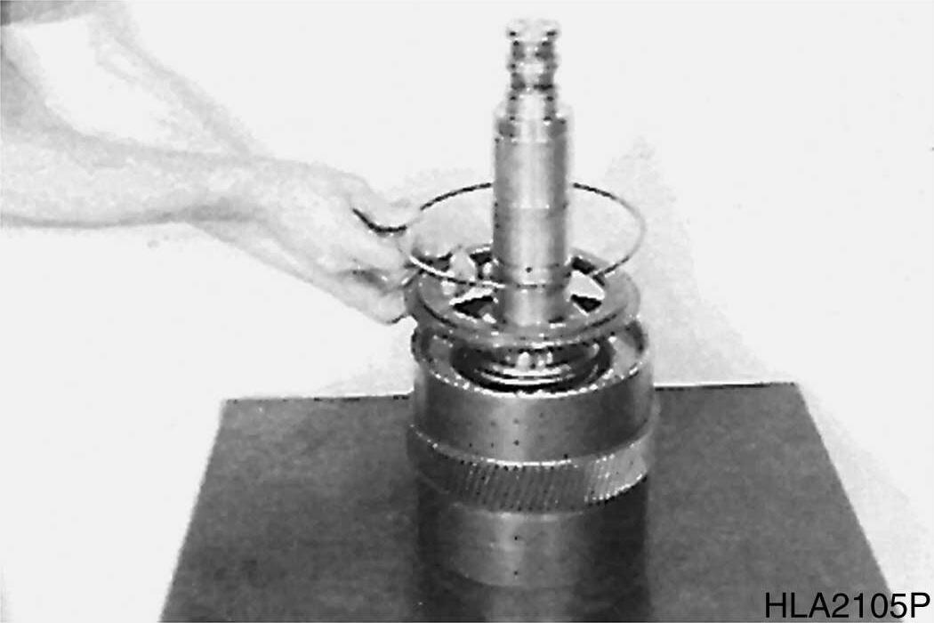
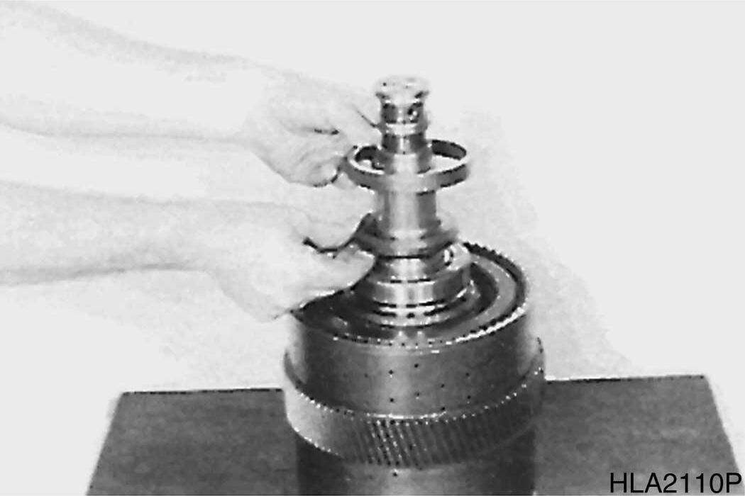
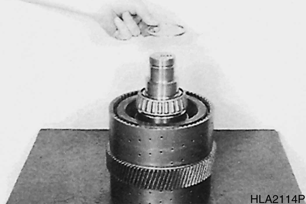
1.Remove snap ring and remove shim(s).
114
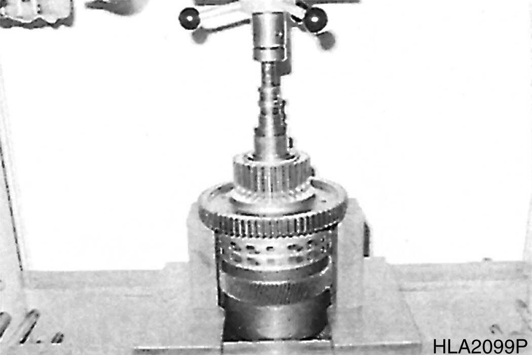
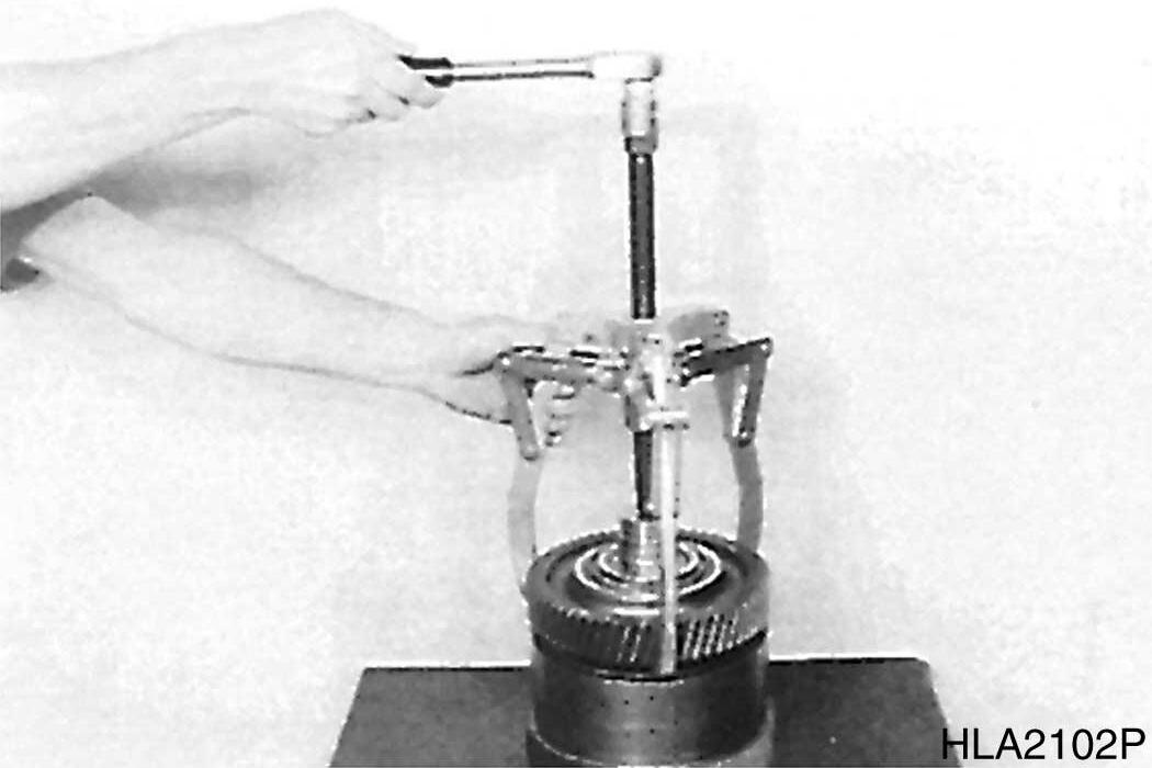
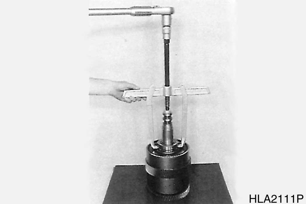
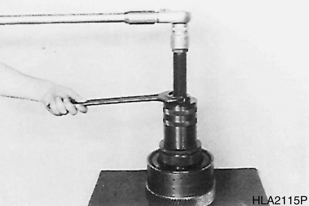
2.Pull PTO shaft by means of internal puller out of housing bore until outer bearing race is released.
115
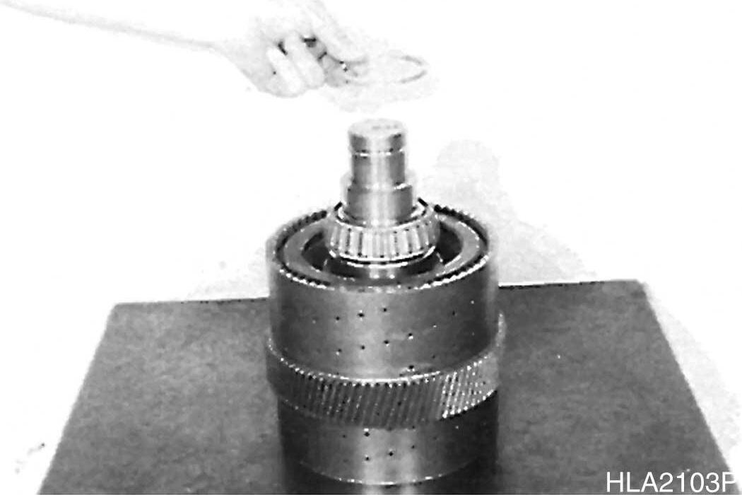
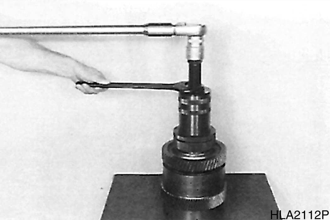
3.Take shaft out of housing.
116
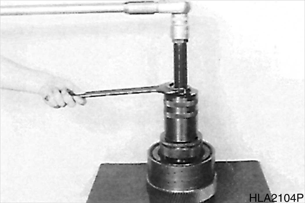
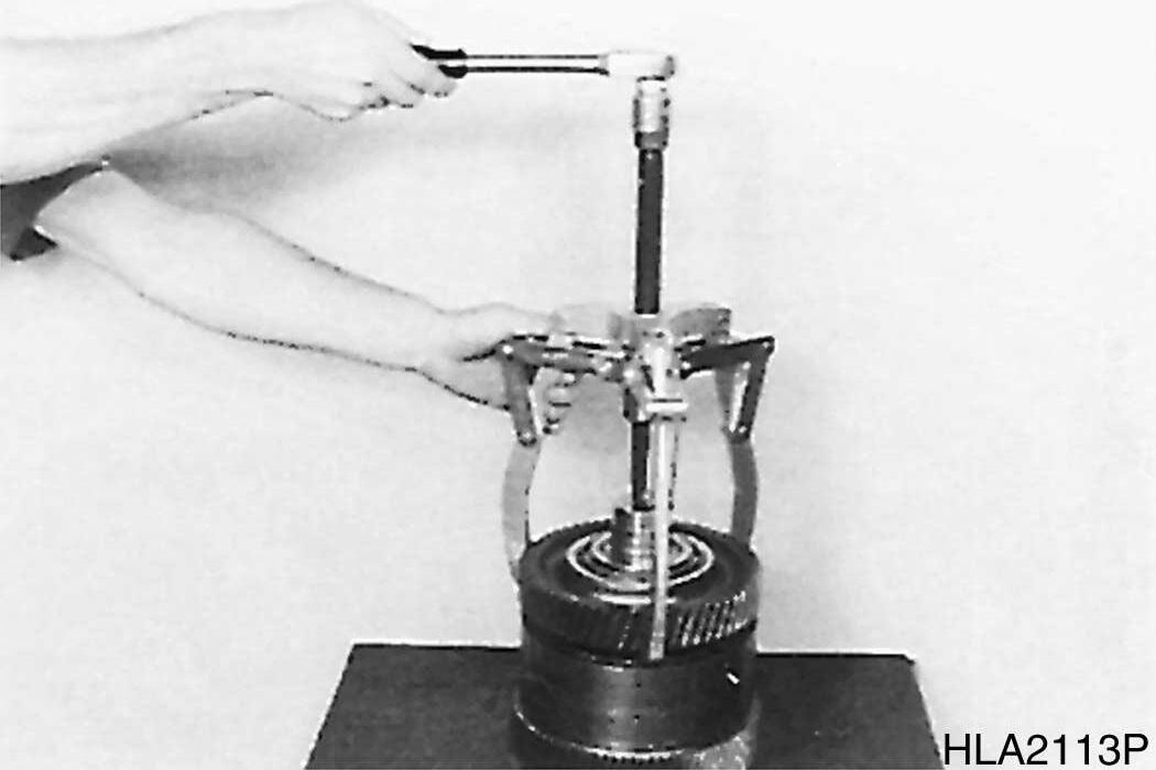
4.Pull inner bearing race from shaft (Figure 117).
5.Press opposite inner bearing race from shaft.
NOTE: Separation of shaft and gear is not possible.
117
Figure
Figure
Figure
Figure
DISASSEMBLE CLUTCHES
Clutch - K3/K4
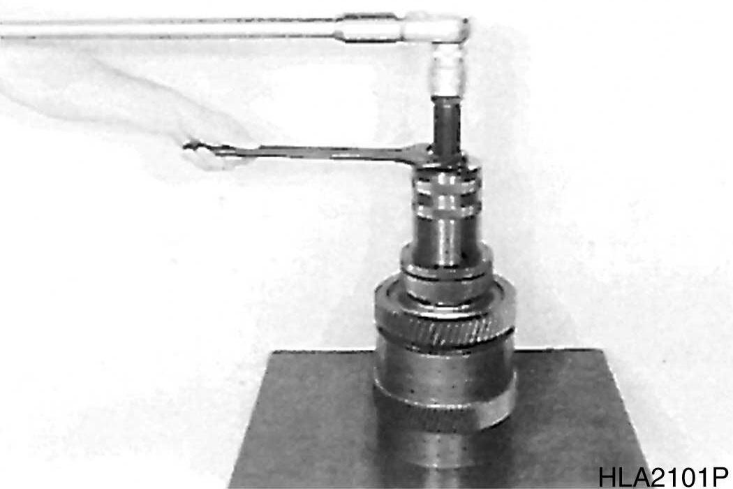
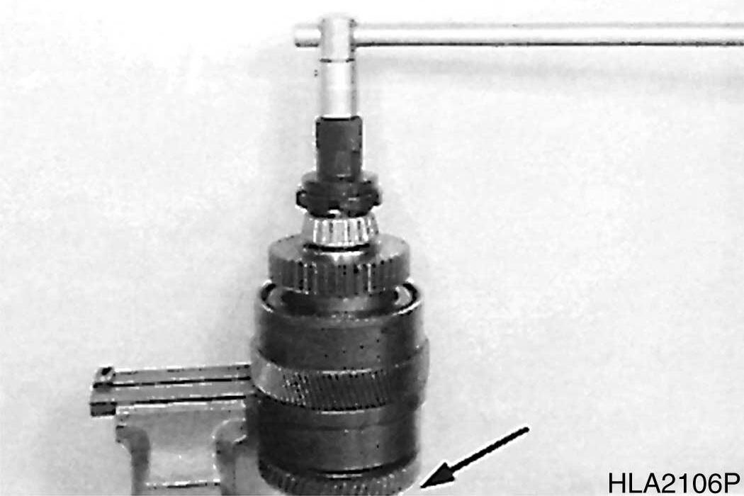
1.Remove three rectangular rings (Figure 118).
118
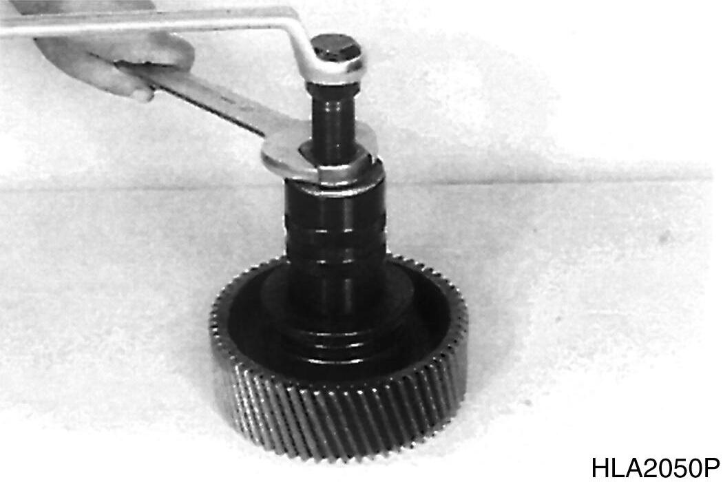
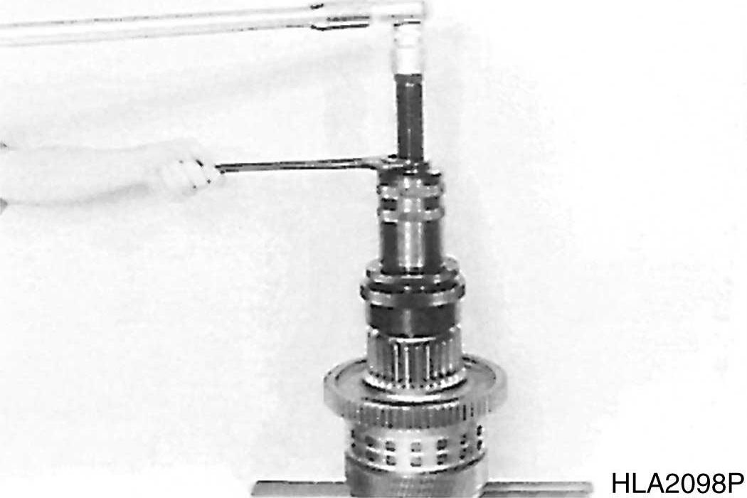
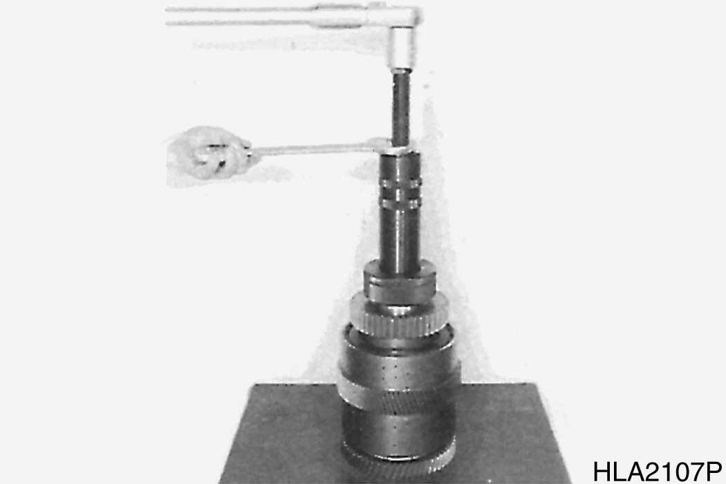
2.Loosen slotted nut.
NOTE: Slotted nut is secured with Loctite.
To prevent damage of thread, heat slotted nut prior to loosen it (about 120°C (248°F)).
3.Pull off taped roller bearing.
119
120
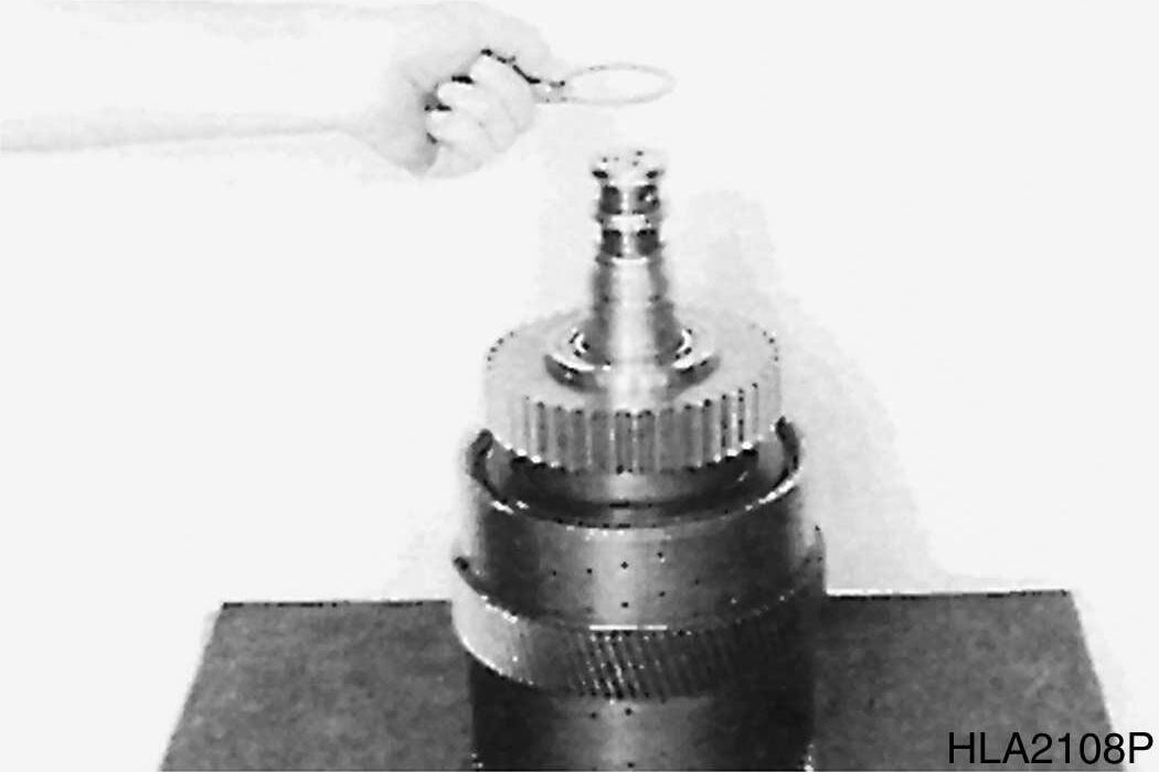
4.Removed flanged disk.
121
S0607070K
Transmission and Torque Converter (ZF)
Figure
Figure
Figure
Figure
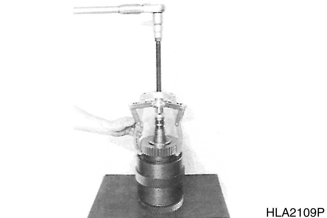
5.Remove upper roller bearing.
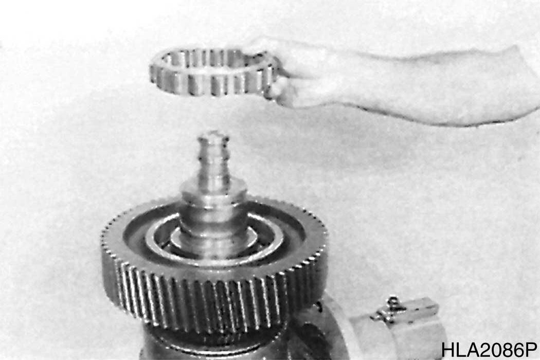
122
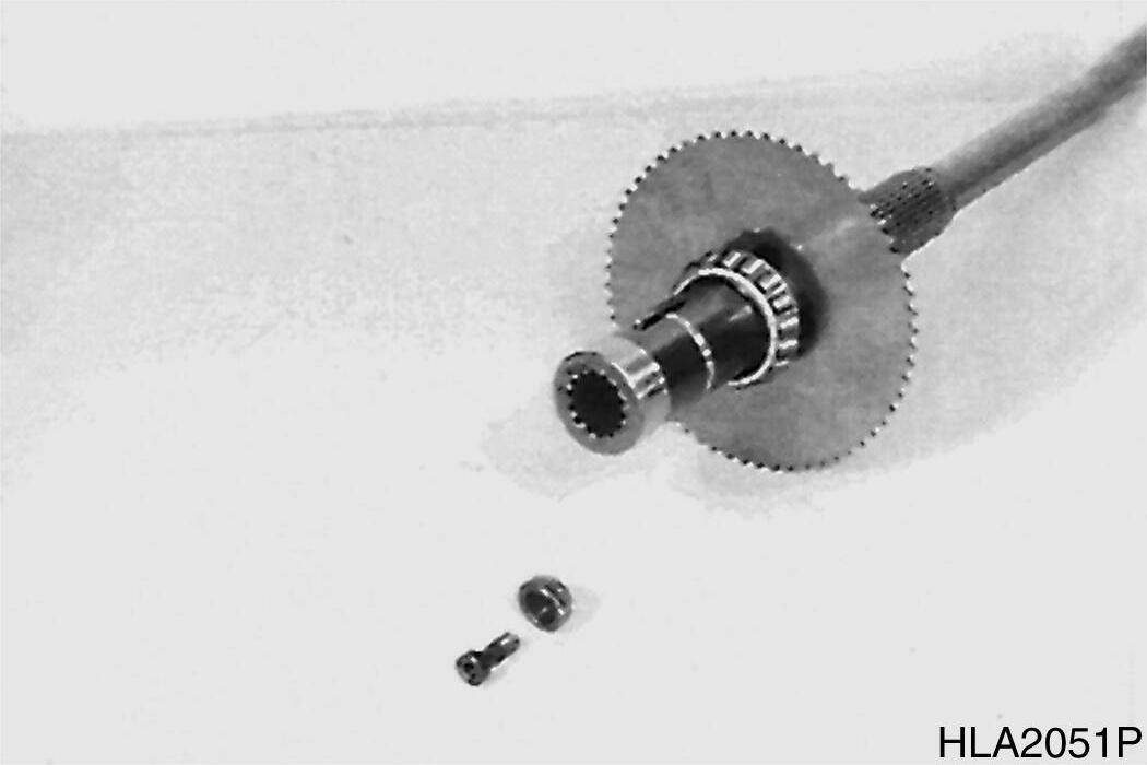
6.Remove angle ring, snap ring, and thrust ring.
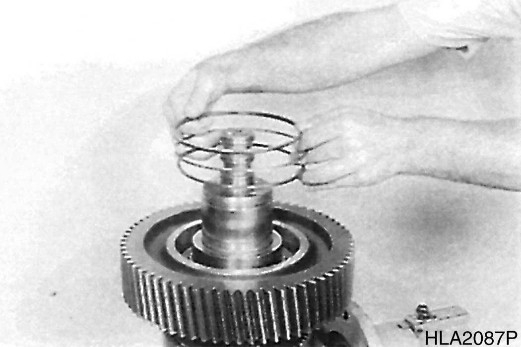
123
7.Press spur gear K3 from plate carrier and remove released roller bearing.
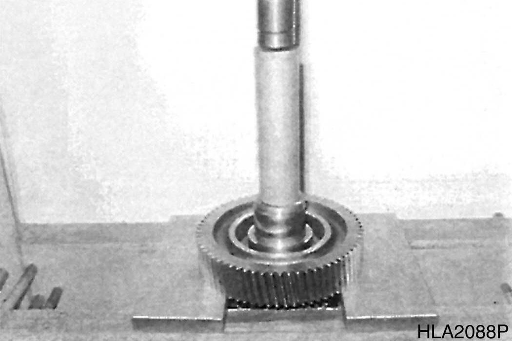
124
8.Remove split ring.
Transmission and Torque Converter (ZF)
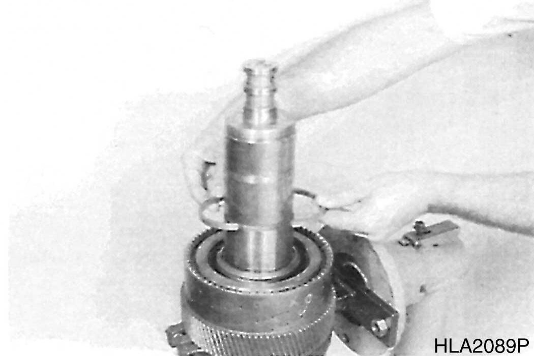
125
Figure
Figure
Figure
Figure
9.Remove snap ring and remove compl. Plate pack K3
10.Tilt clutch 180°
11.Loosen slotted nut.
NOTE: Slotted nut is secured with Loctite. To prevent damage of thread, heat slotted nut prior to loosen it (about 120°C (248°F)).
12.Pull off tapered roller bearing.
13.Pull spur gear from plate carrier.
S0607070K
126
127
128
129
Transmission and Torque Converter (ZF) Return
Figure
Figure
Figure
Figure
14.Remove oil feed ring and pull ball bearing from plate carrier.
130
15.Remove snap ring and remove compl. plate pack - K4.
131
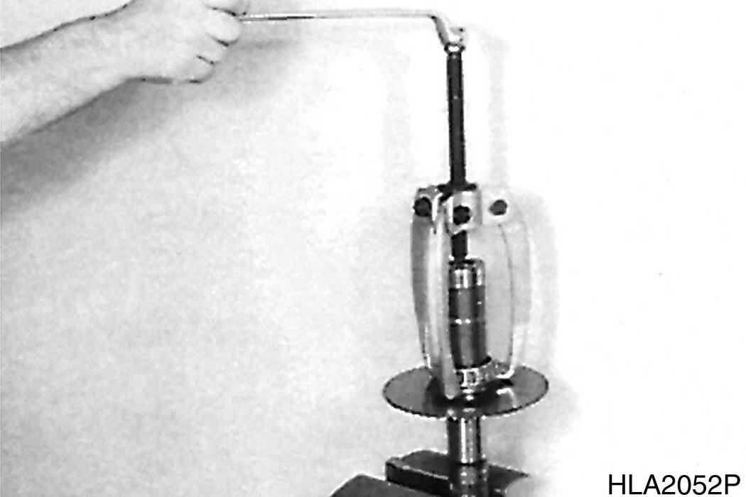
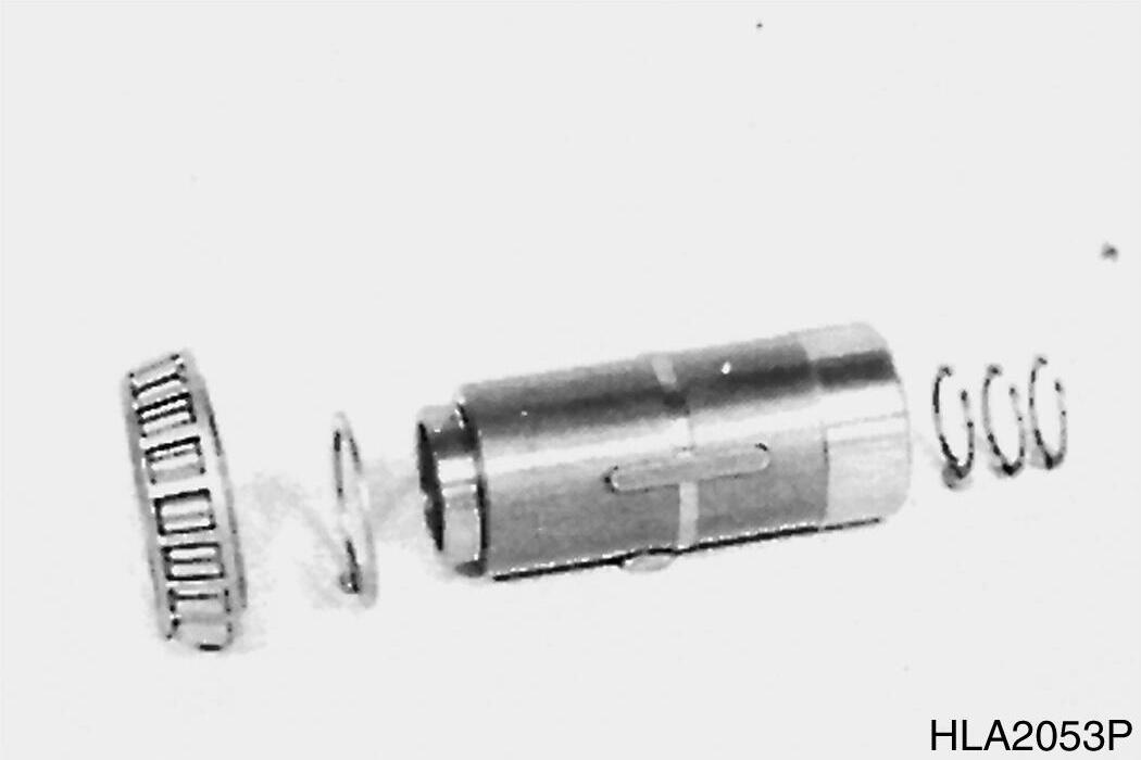
16.Preload compression spring by means of special device (S). Remove snap ring (Figure 132) and released components.
17.Now, separate piston from plate carrier, using compressed air.
18.Disassemble opposite piston accordingly.
Clutch - KR/K2
1.Locate clutch by means of Special device (s) and loosen slotted nut.
2.Loosen opposite slotted nut (Figure 133) accordingly.
NOTE: The slotted nuts are secured with Loctite heat prior to loosen them.
Transmission and Torque Converter (ZF)
132
133
Figure
Figure
Figure
Figure
3.Pull off tapered roller bearing.
134
4.Press spur gear K-2 from shaft.
5.Remove released shim and bush.
135
6.Pull off tapered roller bearing.
136
7.On opposite side, pull off tapered roller bearing.
137
S0607070K
Transmission and Torque Converter (ZF)
Figure
Figure
Figure
Figure
8.Pull spur gear KR from shaft.
9.Remove released inner bearing race, disassemble both outer bearing races and snap ring.
10.Remove adjusting ring.
11.Pull off tapered bearing (spur gear bearing).
12.Disassemble plate packs KR and K2 as well as compression springs and piston (accordingly as at clutch K3/K4.
Transmission and Torque Converter (ZF)
Figure 138
Figure 139
Figure 140
Figure 141
Clutch - KV/K1
1.Loosen slotted nut.
2.Loosen opposite slotted nut (Figure 142) accordingly.
NOTE: The slotted nuts are secured with Loctite and require heating prior to loosen them.
3.Remove tapered roller bearing.
142
143
4.Remove shim.
5.Using a suitable puller remove spur gear K1.
6.Now, remove snap ring and drive ball bearing from spur gear bore.
144
145
S0607070K
Transmission and Torque Converter (ZF)
Figure
Figure
Figure
Figure
7.Remove both rings.
146
8.Using a suitable puller second ball bearing (spur gear bearing).
147
9.On opposite side, pull off tapered roller bearing.
148
10.Pull spur gear KV from shaft.
11.Remove released inner bearing race, disassemble both outer bearing race and snap ring.
149
Figure
Figure
Figure
Figure
12.Remove adjusting ring.
13.Pull off tapered roller bearing (spur gear bearing).
14.Now, remove plate pack KV and K1 as well as compression springs and piston (accordingly as at clutch K3/K4.
S0607070K
Figure 150
Figure 151