
Document Title: Function Group: Information Type: Date: Counterweight, removal 716 Service Information 2015/11/2
Profile:
Counterweight, removal
Op nbr 716-01
–
Lifting eyes 2 pcs. (M30)

WARNING
Heavy lift. Make sure that nobody is standing under the counterweight when it is lifted.
1. Park the machine on a horizontal and stable surface.
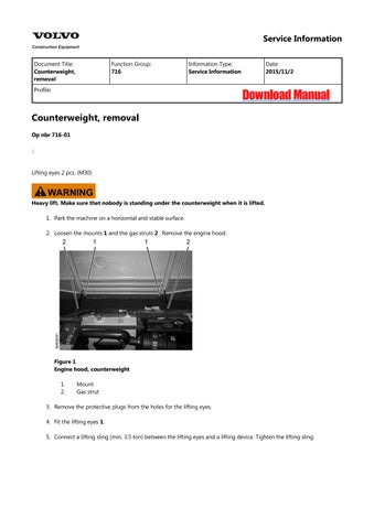
2. Loosen the mounts 1 and the gas struts 2 . Remove the engine hood.

3. Remove the protective plugs from the holes for the lifting eyes.
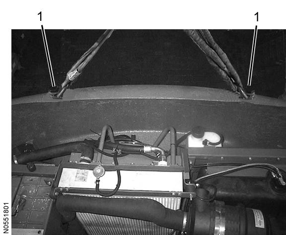
4. Fit the lifting eyes 1.
5. Connect a lifting sling (min. 3.5 ton) between the lifting eyes and a lifting device. Tighten the lifting sling.
Counterweight
1. Lifting eye
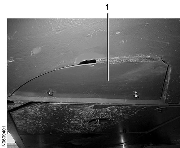
6. Remove the inspection covers 1 (2 hatches, left and right side).
3
Inspection cover, underside of counterweight
1. Inspection cover
7. Unplug the connectors 1 for the tail lights (2 connectors, left and right side).
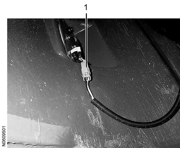
Inside of counterweight
1. Connector
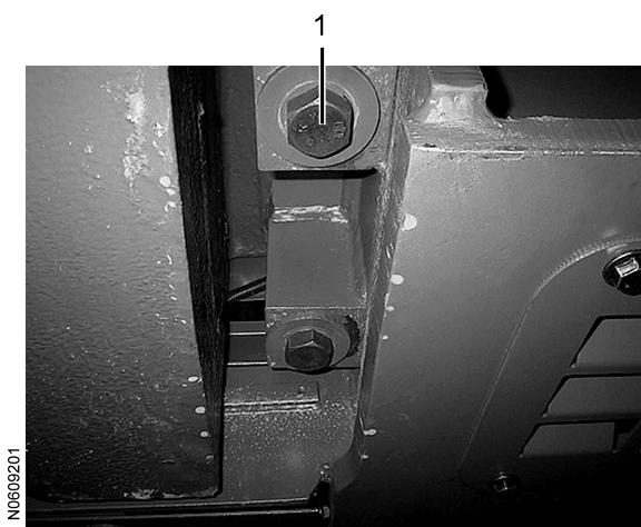
8. Remove the bolts 1 (4 bolts).
9. Lift away the bolt supports (2 supports) on the inside of the counterweight.
10. Carefully lift away the counterweight. Make sure that the fan motor is not damaged. NOTE!
Check and note the number of spacers 1 by the mounts.
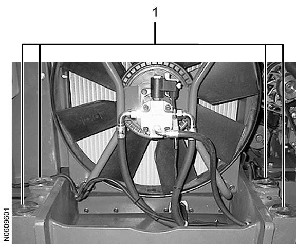
Spacers
11. Lower the counterweight on a horizontal, firm surface and support it so that it cannot fall over.
12. Remove the lifting sling.
Document Title: Function Group: Information Type: Date:
Counterweight, installation 716 Service Information 2015/11/2
Profile:
Counterweight, installation
Op nbr 716-02
–
Lifting eyes 2 pcs. (M30)
WARNING
Heavy lift. Make sure that nobody is standing under the counterweight when it is lifted.
1. Check that the number of spacers 1 corresponds to the number previously noted. NOTE!
Centre the spacers in relation to the holes.
Figure 1
Counterweight mount
1. Spacers
2. Connect a lifting sling (min. 3.5 ton) between the lifting eyes 1 and a lifting device. Tighten the lifting sling.
3. Carefully lift the counterweight into position. Make sure that the fan motor is not damaged. NOTE!
The spacers must not move out of position when the counterweight is lowered.
Counterweight
1. Lifting eye
4. Fit the bolt supports (2 supports) on the inside of the counterweight.
5. Fit the bolts 1 (4 bolts) and tighten them.
Tightening torque: 900 Nm.
Figure 3
Counterweight mount
1. Bolt
6. Remove the lifting sling from the lifting eyes.
7. Remove the lifting eyes and fit the protective plugs in the holes.
8. Plug in the connectors 1 for the tail lights (2 connectors, left and right side).
Figure 4
Inside of counterweight
1. Connector
9. Fit the inspection covers 1 (2 covers, left and right side).
5
Inspection cover, underside of counterweight
1. Inspection cover
10. Fit the engine hood by fastening the mounts 1 and gas struts 2
Document Title: Function Group: Information Type: Date:
Undercarriage, description 7181 Service Information 2015/11/2
Profile:
Undercarriage, description
Each track is driven by a two-step axial piston motor. There is a retardation valve integrated in the axial piston motor that automatically restricts the oil supply in case of excessive speed. The track brakes are of the disc type and are integrated in the planetary gearbox. The brakes are applied by spring force and are released hydraulically (negative brake). The travel motor and gears are built into the gearbox.
The frame is all-welded and consists of two track frames and a mid-section with four horizontal beams forming an X-shape. The superstructure is rotated by a low-speed radial piston motor. There is a negative slew brake in the radial piston motor Between the engine and the slew ring, there is a slew gear engaged with gears on the inside of the ring gear. The slew ring connects the superstructure with the undercarriage and is lubricated by grease. A centre passage provides the hydraulic components in the undercarriage with hydraulic oil.

NOTE: If there is no response to click on the link above, please download the PDF document first and then clickonit.
Document Title: Function Group: Information Type: Date: Front wheel, installation 7751 Service Information 2015/11/2
Profile:
Front wheel, installation
Op nbr 7751-02
14 290 046 Track bolt press
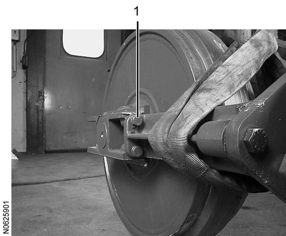
1. Fit the front wheel. Tighten the bolts 1 (4 bolts). Tightening torque: 85 Nm
3. Clean the guides in the track frame.
4. Lift the front wheel into position.
facilitate installation.
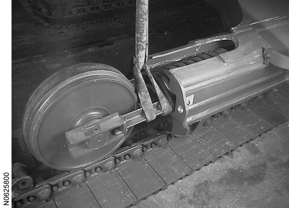
5. Remove the sling.
6. Push the front wheel into place using a crow bar.
7. Fit the track according to Track, fitting