
Document Title: Function Group: Information Type: Date:
Track gearbox, description Service Information 2015/5/20
Profile:
EXC, EC160B NLC [GB]
Track gearbox, description
Download Manual
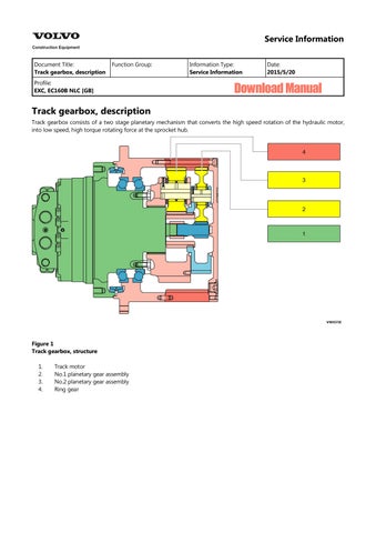
Track gearbox consists of a two stage planetary mechanism that converts the high speed rotation of the hydraulic motor, into low speed, high torque rotating force at the sprocket hub.
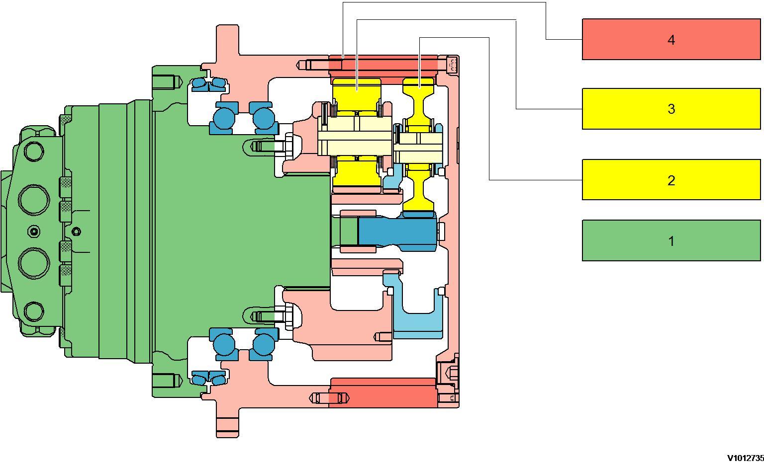
Track motor
No.1 planetary gear assembly
No.2 planetary gear assembly Ring gear
Document Title: Function Group: Information Type: Date:
Track gearbox, precautions for operation Service Information 2015/5/20
Profile:
EXC, EC160B NLC [GB]
Go back to Index Page
Track gearbox, precautions for operation
Installation
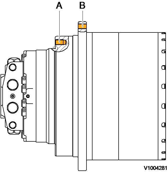
Figure 1
Mounting location
A. B. Main body mounted area Sprocket mounted area
Check that the mating mount surfaces are clean.
Check that the motor is positioned correctly in the frame.
If the gearbox to frame fit is tight, draw the assembly into the frame evenly with the mounting screws.
Tighten the screws in a crisscross pattern in several stages to the specified torque. Apply these same precautions when mounting the sprocket.
Tightening torque
Tightening torque, unit: kgf·m (lbf·ft)
Gearbox screw (A) 30 M16 (P2.0) 27 ± 3 (195 ± 22)
Sprocket screw (B) 22 M16 (P2.0) 27 ± 3 (195 ± 22)
NOTE!
The screws must be 10.9 KS strength classification or above.
Lubricating oil
NOTE!
Prior to operating the travel function, fill the gearbox with the specified oil to the correct level.
NOTE!
Gear specification
Use a gear oil equivalent to API classification GL4 / GL5 with EP (Extreme Pressure) additives
Gear oil replacement period
First (initial) oil replacement: 500 operating hours
Subsequent oil replacement: 2000 operating hours
After maintenance (initial): 250 operating hours
NOTE!
Regardless of the operating hours the gear oil must be replaced at least once per year.
NOTE!
Do not mix different types, classifications or brands of oil.
NOTE!
Drain the gear oil while it is still warm to flush out any contaminants.
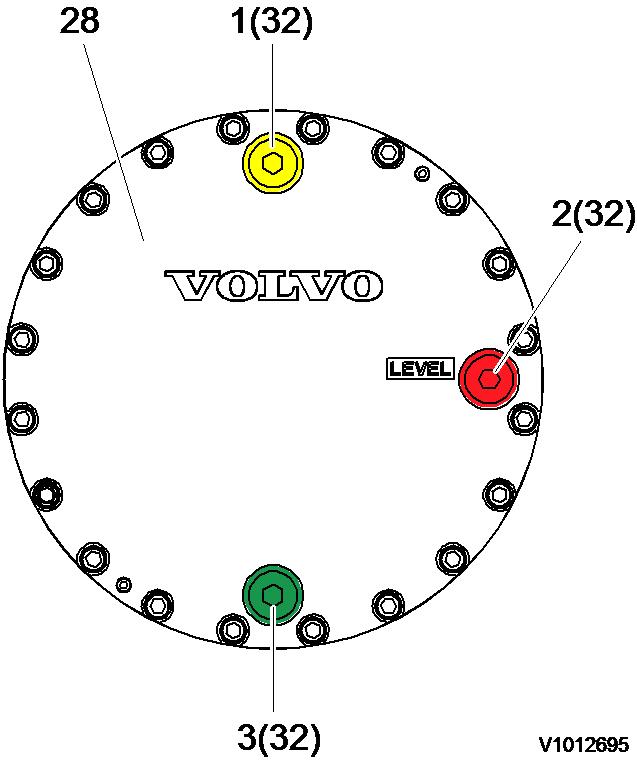
Gear oil replacement procedure
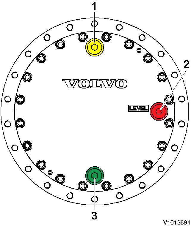
Level check port Drain port
Rotate the gearbox until the drain plug and the fill plug are on the vertical axis.
Remove the 3 plugs in the end cover and drain the oil into a suitable container.
Ensure that the drain plug O-ring is not damaged, then install the plug and torque to specification
Refill the gearbox through the fill port until oil exits from the level check port.
Ensure that the O-ring on each plug is not damaged, then install the plugs and torque to specification.
NOTE!
Oil capacity: 5.8 Liter (1.5 gal)
Operating checks
Check the oil level prior to operating the travel function.
Check for oil leakage on the gearbox assembly.
Check for loose mounting screws.
Check for abnormal sound or vibration while rotating.
Check for any abnormal temperature increase after operating for a short time.

WARNING
The temperature of the case is high just after running. Do not touch directly by hand to prevent a burn injury. Check
the temperature with a surface thermometer.
NOTE!
The temperature of the case must be lower than 90 °C (194 °F), during continuous operation.
Document Title: Function Group: Information Type: Date:
Track gearbox, principle of operation Service Information 2015/5/20
Profile:
EXC, EC160B NLC [GB]
Go back to Index Page
Track
gearbox,
principle of operation
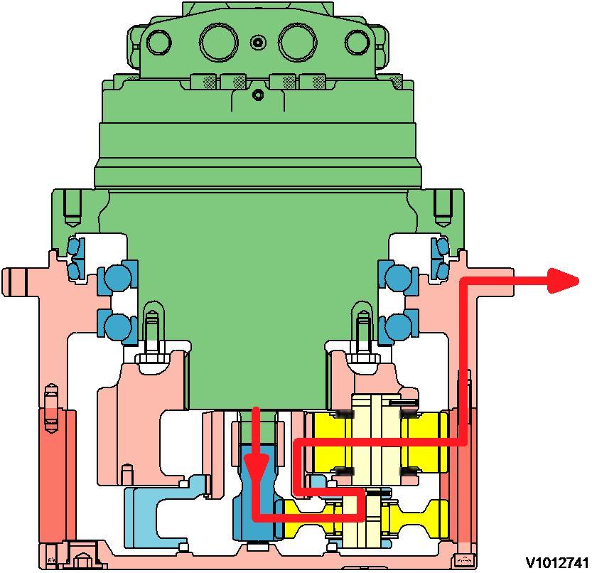
Figure 1
Track gearbox, torque flow
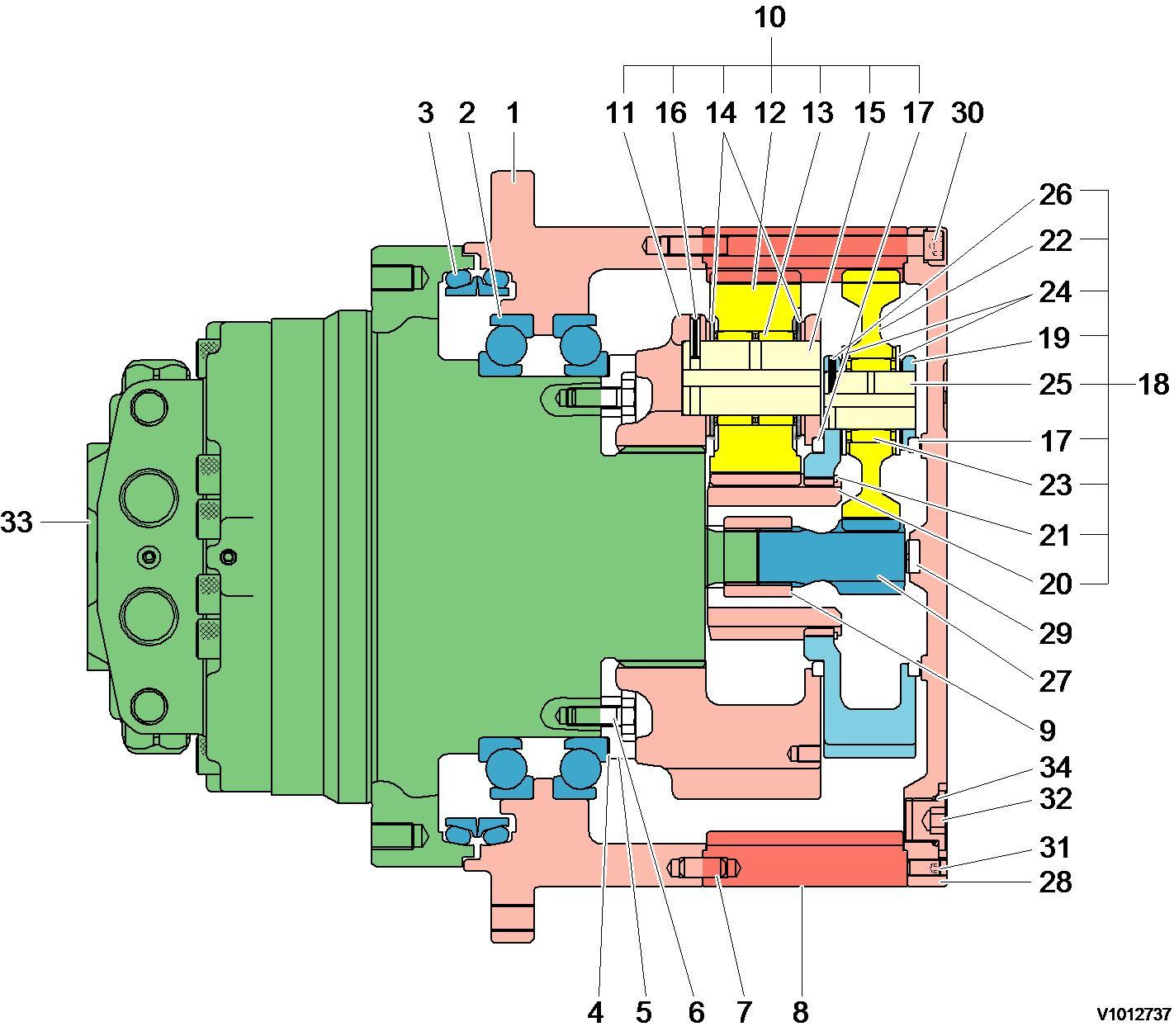
The power transmitted from the hydraulic motor output shaft is transmitted to the 1st stage sun gear (27) → spline of 1st carrier (19) → 2nd sun gear (20) → 2nd planetary gear (12) → ring gear (8). At this time, the reduction ratio of reduction gear is as follows:
(1) 1st reduction ratio
i1 = ((Zs1 + Zr) · (Zs2 + Zr)) / (Zs1 · Zs2) - 1
Zs1 = No. of tooth of 1st sun gear
Zs2 = No. of tooth of 2nd sun gear
Zr = No. of tooth of ring gear
Document Title: Function Group: Information Type: Date:
Track gearbox, troubleshooting Service Information 2015/5/20
Profile:
EXC, EC160B NLC [GB]
Track gearbox, troubleshooting
Track gearbox troubleshooting
Gearbox does not rotate.
Oil leakage from mating joint surfaces.
Motor overloaded. Reduce the load.
Gearbox is damaged.
Replace the gearbox.
Liquid gasket improperly applied. Disassembly and re-apply.
Mating surface damaged.
Loosen screws.
Loosen plug.
Casing leakage.
Floating seal leakage.
Cracks or pin holes.
Cover damaged.
Sliding surface worn.
O-ring distorted.
Repair or replace.
Tighten to specified torque.
Tighten to specified torque.
Replace the housing.
Replace the cover.
Replace the floating seal assembly.
Abnormal operating temperature. Insufficient gear oil. Refill to specified level.
Gear or bearing damaged.
Replace the gearbox.
Abnormal operating sound.
Hydraulic and gear oil mixed. Replace the motor oil seal.
Gearbox is damaged.
Replace the gearbox.
Document Title: Function Group: Information Type: Date:
Track gearbox, removal Service Information 2015/5/20
Profile:
EXC, EC160B NLC [GB]
Track gearbox, removal
Op nbr 00000
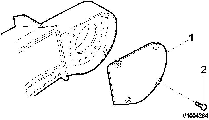
Figure 1
Removal, cover
1. Remove cover screw (2), and remove cover (1).
2. Remove the track.
3. Place a wooden block on the track, and place the lower roller on the block to raise the sprocket off the track.
4. Disconnect the hydraulic hoses at the track motor. Plug the pipe ends and ports to prevent the outflow of oil and the entry of contamination.
5. Remove the track motor mounting screws from the undercarriage.
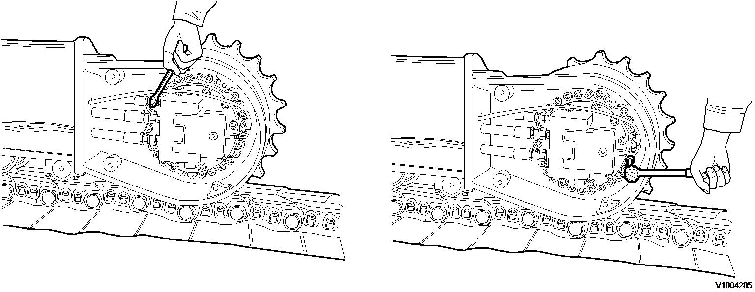
Figure 2
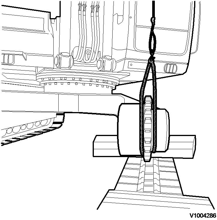
Removal, hydraulic hoses and screws
6. Pass a wire rope around the gearbox, and lift it. Remove the track motor as an assembly. Then, using screws in the threaded holes of the undercarriage, force out the gearbox.
3
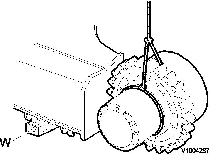
Removal, track gearbox
NOTE!
Lift the gearbox as close to the sprocket as possible to maintain balance.
NOTE!
The gearbox mounting screws may be used in the threaded frame holes.
NOTE!
Putting match-marks on the track frame and track gearbox will facilitate reassembly.
Document Title: Function Group: Information Type: Date:
Track gearbox, installation Service Information 2015/5/20
Profile:
EXC, EC160B NLC [GB]
Track gearbox, installation
Op nbr 00000
NOTE!
Carefully check the mating surface of the undercarriage and the gearbox for burrs, dirt and rust scale.
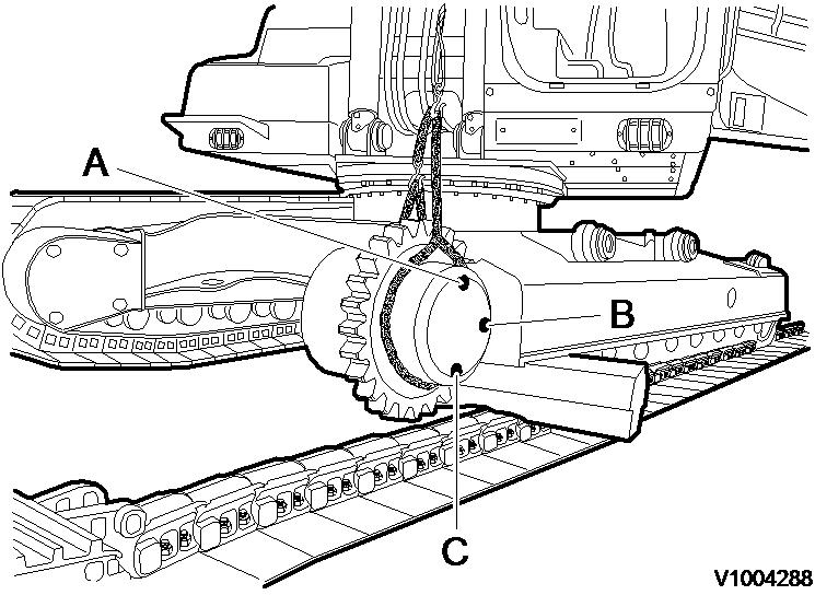
1. Pass a wire rope around the gearbox, lift and install the gearbox to the undercarriage.
Installation, track gearbox
2. Apply loctite # 277 to the gearbox mounting screws, and tighten them to the specified torque.
Tightening torque: 27 ± 3 kgf·m (195 ± 22 lbf·ft)
3. Connect the hydraulic hoses at the track motor.
4. Install the gearbox cover.
Checking, oil level
Fill port Level check port Drain port
5. Check the gear oil level of gearbox. If necessary, replace or refill the oil.

NOTE: If there is no response to click on the link above, please download the PDF document first and then clickonit.
Document Title: Function Group:
Type: Date: Track gearbox, maintenance standard
Profile:
EXC, EC160B NLC [GB]
Track gearbox, maintenance standard
The parts are precision finished and must be handled carefully. Keep the parts of the planetary carrier (s) together, do not mix the bearings, gears, pins and thrust washers.
Seals
Replace the seals, oil seal and O-ring, although they appear not damaged.
Part replacement criteria
Replace all parts that appear damaged or are not within the allowable value. Replace some parts in sets, i.e. gears, bearings, pins and thrust washers.
Part replacement criteria
The tooth surface is pitted or non uniformly worn.
The gear is cracked.
Fitting/flaking of the balls, rollers or races. Does not rotate smoothly by hand. 3
Rust or damage on sliding face. O-ring distorted or damaged.
The pin is cracked, galled or pitted.
Excessively worn on the face area.
Check that the gearbox axis is horizontal. Rotate the gearbox housing until the drain plug is on the bottom of the vertical axis of the end cover.
The gearbox is supplied with oil plugs (draining, filling and level) equipped with an hole that allows the air to bleed.
NOTE!
Remove the oil plugs with care. When the gearbox is warm, the air inside can be pressurized and this can cause their strongly expulsion towards the worker.
Loose with caution the plugs (2~3 rounds) counterclockwise.
Clean the plug to be sure that the air bleed hole is not obstructed. Wait a few seconds to allow the pressurized air to bleed from the gearbox. Remove the plugs and let the oil flow in a large enough container; in order to facilitate the draining must be oil still warm.
Wait a few minutes until all the oil is drained and then proceed to screw on the plugs. Proceed with the oil fill-up following the procedures given.
NOTE!
Never mix mineral oils with synthetic oils and vice versa.
Do not dispose of the oil in the natural environment but be careful to eliminate it in compliance with the relative rules and regulations that govern locally.
Tightening torque plug. See track gearbox, description.
Document Title: Function Group: Information Type: Date:
Track gearbox, disassembly Service Information 2015/5/20
Profile:
EXC, EC160B NLC [GB]
Track gearbox, disassembly
Op nbr 00000
Precautions
Thoroughly clean the gearbox assembly prior to disassembly.
Select a clean work area.
Match mark attached components to indicate proper positioning during reassembly.
Take care not to mix parts of sub assemblies i.e. planetary bearings, gears and thrust washers.
Thoroughly clean all parts and the inside of the casings.
Inspect and analyse all failures. – Determine the root cause!
1. Place the oil fill port and the oil drain port on the vertical axis. Remove plug (32) and drain the gear oil.
Tools: L wrench 12 mm (PF 3/4), 8 liter pan
NOTE!
Drain oil into a clean container and check thoroughly for contamination.
2. Remove screws (30) and remove cover (28).
Tools: L wrench 10 mm, 5 mm
NOTE!
Install a screw (31) and carefully lift the cover off.
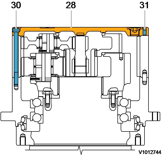
2
Removal, screw and cover WARNING
The parts are heavy. Take appropriate safety precautions.
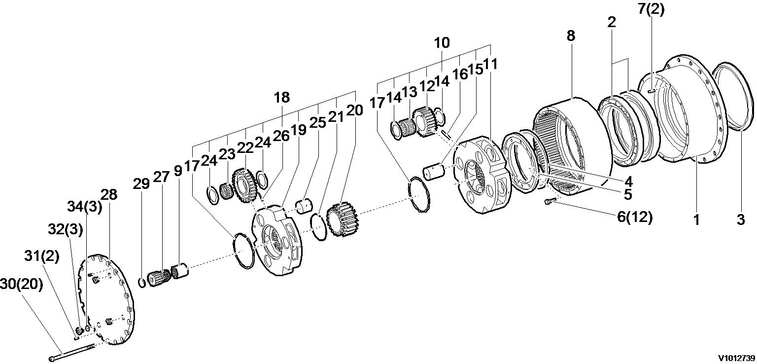
3. Remove No.1 planetary gear assembly (18) from No.2 planetary gear assembly (10).
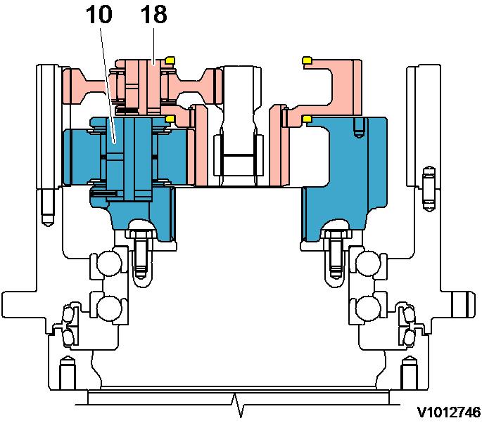
Figure 3
Removal, No.1 planetary gear assembly
Disassemble No.1 planetary gear assembly.
Tap spring pin (26) into No.1 pin (25).
Remove thrust washer (24), No.1 planetary gear (22) and needle bearing (23) from No.1 carrier (19).
Remove thrust ring (17).
Remove retaining ring (21), then No.2 sun gear (20).
Remove thrust ring (17).
Tools: Eye bolt (M10), plastic hammer
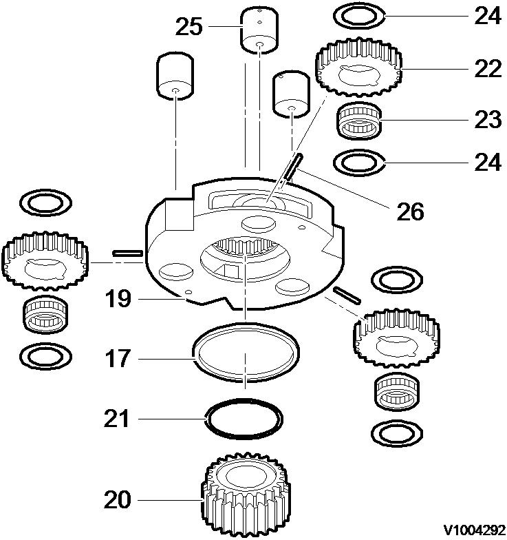
Figure 5
Removal, spring pins
NOTE!
Match mark gears (22), pins (25) and carrier (19).
NOTE!
Do not mix the gears, bearings, thrust washers, and pin assemblies.
NOTE!
Do not reuse spring pins (26).
NOTE!
If there are any flakes at the surface of No.1 pin, replace No.1 pin, No.1 carrier (28), No.1 planetary gear (33) and needle bearing (34) simultaneously.
4. Remove No.1 sun gear (27) and coupling (9).
NOTE!
Remove No.1 carrier (19) and then remove No.2, No.1 sun gear (20, 27).
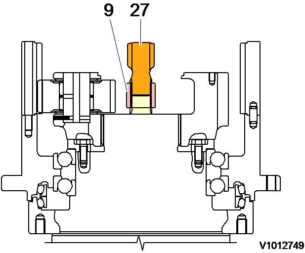
Figure 6
Removal, No.1 sun gear and coupling WARNING
The parts are heavy. Take appropriate safety precautions.
5. Remove No.2 planetary gear assembly (10) from spindle (302).