

SCORPION
9040 (404-03)
7045 (403-03)
7040 (402-03)
7030 (401-03)
6030 (400-01)
Repair Manual
Table of Contents
4Engine
5.26Test report for model 400/401/402 with H1 pump without auxiliary motor (0–40kph) 5-36
5.27Test report for model 403/404/402 with TMP89 pump and auxiliary motor (fixed displacement motor) (0 – 40 kph) 5-37
5.28Test report for model 403/404 diesel engine 103 kW and TMP89 pump and auxiliary motor (variable displacement motor) (0 – 40 kph) 5-38
5.29Test
5.45Variable
5.46Checking
5.50Measurement
5.54Report:
8Steering system
8.1Electrical/hydraulic
8-2
8.2Electrical/hydraulic diagrams for steering system from serial no. 400 01 0168, 401 03 0196, 402 03 0177, 403 03 0146, 404 03 0147, 8-4
8.6Steering
Table of Contents
8.7Steering circuit with variable displacement pump (LS = load sensing) ............................................................................ 8-9
8.8Hydraulic steering diagram: priority valve – variable displacement pump (LS = load sensing) 8-10
8.9Steering circuit with gear pump ..................................................................................................................................... 8-11
8.10Hydraulic steering diagram: priority valve – gear pump .................................................................................................
8.11Hydraulic
8.14Hydraulic steering diagram: diagonal steering with diagonal steering valve (crab steering) ......................................... 8-16
8.15Hydraulic steering diagram: 4 wheel steering with diagonal steering valve (crab steering) 8-17
8.16Steering
8.19Front
9Work hydraulics
9.1Work hydraulics fixed displacement pump (diagram) – raising/lowering the telescopic boom (HUSCO) ........................ 9-2
9.2Work hydraulics fixed displacement pump (diagram) – raising/lowering the telescopic boom (Bucher) ......................... 9-4
9.3Work hydraulics variable displacement pump (diagram) – raising/lowering the telescopic boom (HUSCO) ................... 9-6
9.4Work hydraulics variable displacement pump (diagram) – raising/lowering the
9.7Work hydraulics (diagram) – extending/retracting the telescopic boom, fixed displacement pump (HUSCO) .............. 9-14
9.8Work hydraulics fixed displacement pump (diagram) – extending/retracting the telescopic boom ............................... 9-16
9.9Work hydraulics variable displacement pump (diagram) – extending/retracting the telescopic boom (HUSCO) .......... 9-18
9.10Work hydraulics variable displacement pump (diagram) – extending/retracting the telescopic boom (Bucher)
9.11Work
9.12Extending/retracting the telescopic boom (electrical diagram) ...................................................................................... 9-24 9.13Retracting/extending
9.33Work
(diagram)
(HUSCO)
(diagram) – additional control circuit, Autohitch (Bucher) ...................... 9-68
9.35 Work hydraulics fixed displacement pump (diagram) – rear additional control circuit, Autohitch, tipping trailer (HUSCO) 9-70
9.36Work hydraulics fixed displacement pump (diagram) – additional control circuit, Autohitch, tipping trailer (Bucher) .... 9-72
9.37Work hydraulics variable displacement pump (diagram) – rear additional control circuit, Autohitch, tipping trailer (HUSCO)
9-74
9.38Work hydraulics variable displacement pump (diagram) – additional control circuit, Autohitch, tipping trailer (Bucher) 9-76
9.39Work
9.40Work
9.44Work
9.55Work hydraulics variable displacement pump (diagram) – additional control circuit for quick couplers on telescopic
(HU SCO) 9-110
9.56Work hydraulics fixed displacement pump (diagram) –
9.103Changeover
AAppendix
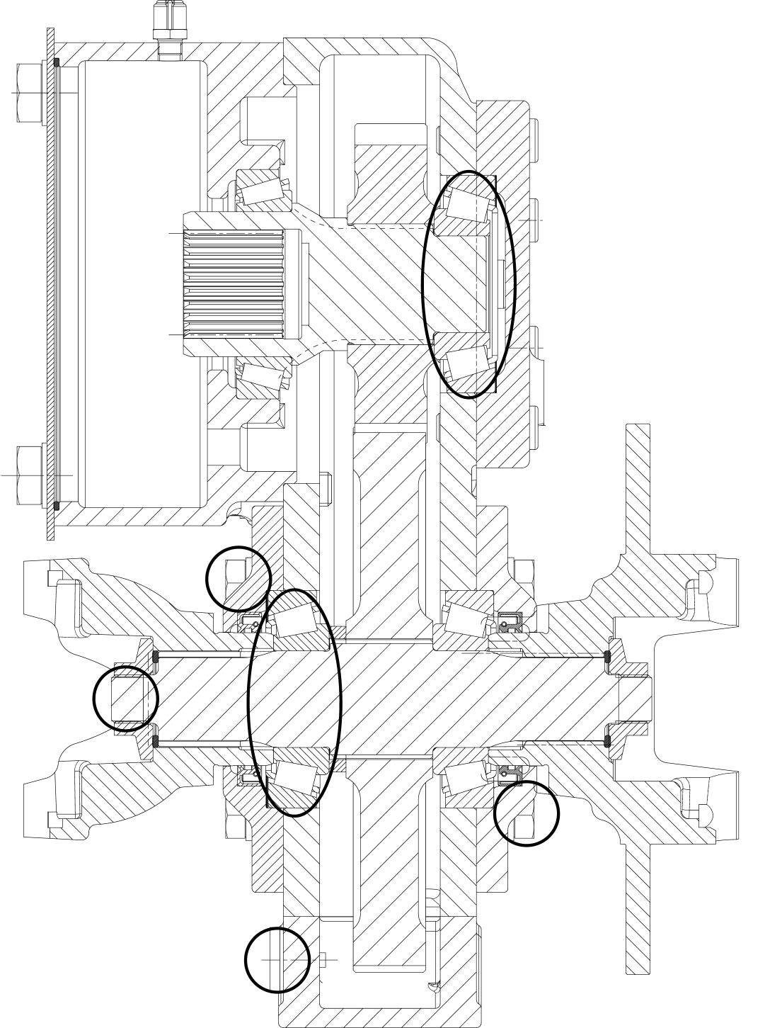
6.620 kph gearbox (overview)
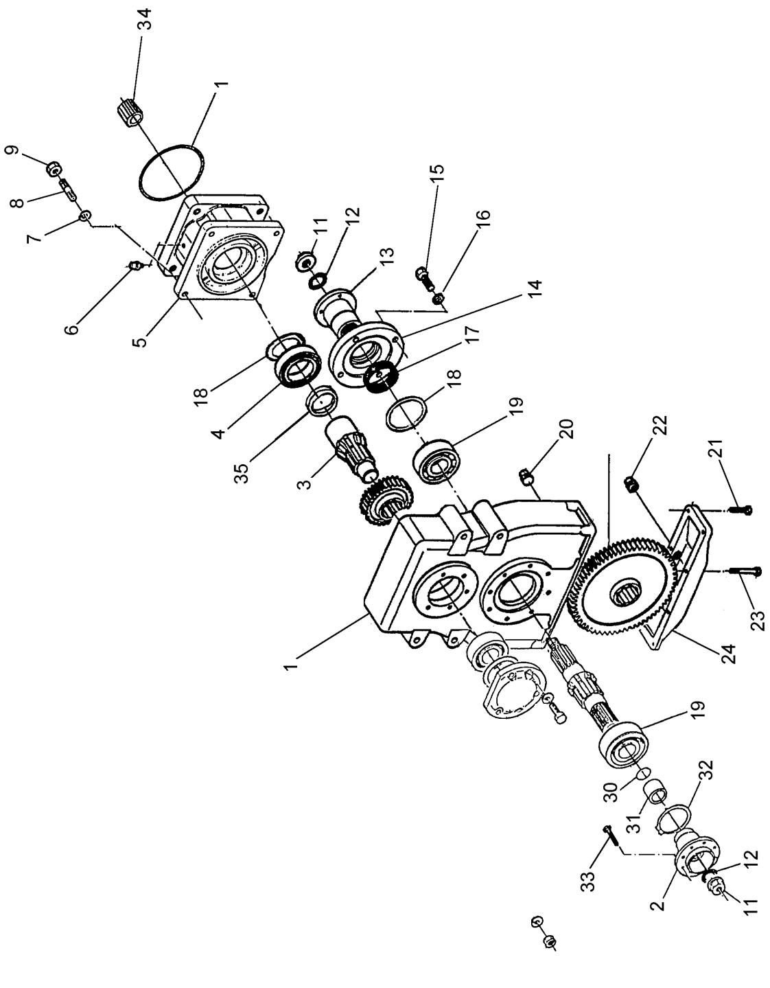
Flanged hydraulic motor
6.7Removing the 20 kph gearbox
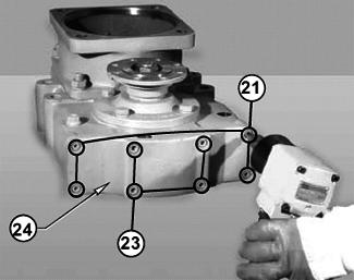
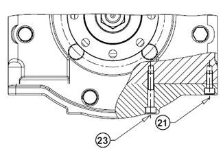
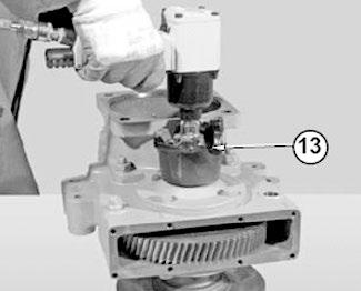
☞ Unscrew fastening screws 21 and 23 from cover 24
Caution!
Different lengths
☞ A flange is installed on either side
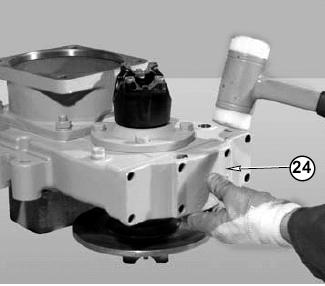
☞ Remove cover 24
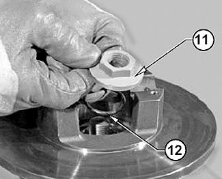
☞ Slacken the fastening nut on flange 13
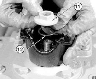
☞ Remove nut 11 and O-ring 12
Caution!
A normal flange is installed on the telehandler
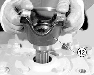
☞ Remove flange 12
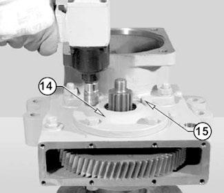
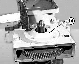
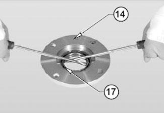
☞ Unscrew fastening screws 15 from cover 14
☞ Remove cover 14
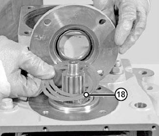
☞ Remove spacers 18
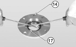
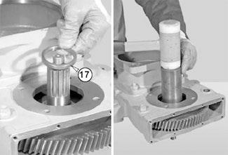
☞ Remove sealing ring 17 from cover 14
Axles/differential lock
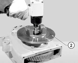
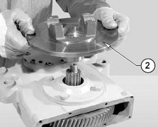
☞ Slacken the fastening nut on flange 2
Caution!
A normal flange is installed on the telehandler
☞ Remove nut 11 and O-ring 12
☞ Remove flange 2
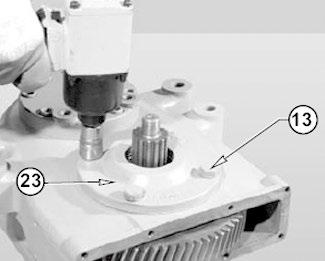
☞ Unscrew fastening screws 13 from cover 23
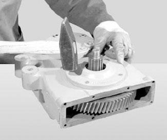
☞ Slacken cover 23

☞ Remove cover 23
☞ Lever out sealing ring 17
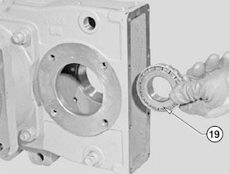
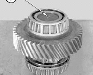
☞ Remove outer ring 19
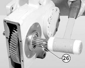
☞ Remove shaft 26
☞ Remove shaft 26
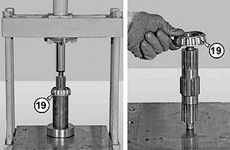
☞ Press out bearing 19
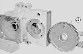
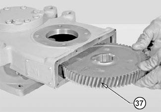
☞ Remove gear 37
☞ Remove bearing 19
☞ Expel outer ring 19
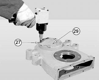
☞ Remove fastening screws 27 from cover 29
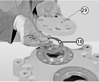
☞ Remove cover 29 and washers 18
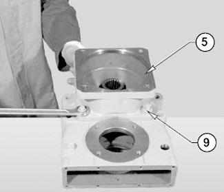
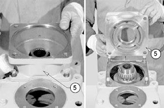
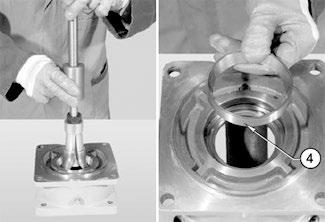
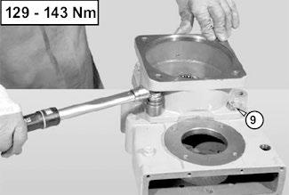
☞ Unscrew fastening screws 9 from connection housing 5
☞ Remove connection housing 5
☞ Remove bearing 4 from the housing with an extractor
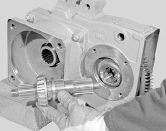
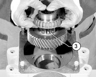
☞ Remove upper shaft 3
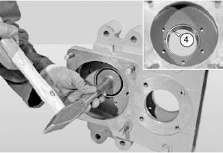
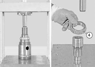
☞ Remove outer ring 4
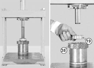
☞ Position shaft 3 under a press
☞ Press out gear 38 and bearing 19
☞ Press out bearing 4
6.8Installing the 20 kph gearbox
260 – 280 Nm
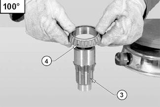

☞ Install bearing 4 on shaft 3
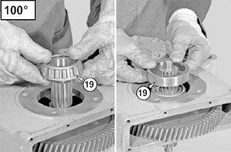
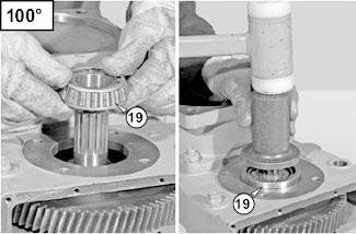
➥ Heat the bearing to 100 °C
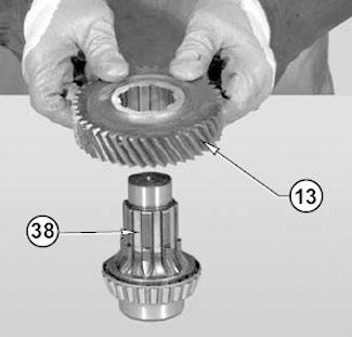
☞ Install gear 13 on shaft 38
☞ Install bearing 19 on shaft 38
➥ Heat the bearing to 100 °C
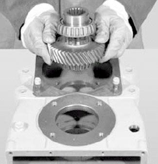
☞ Install the complete shaft in the housing
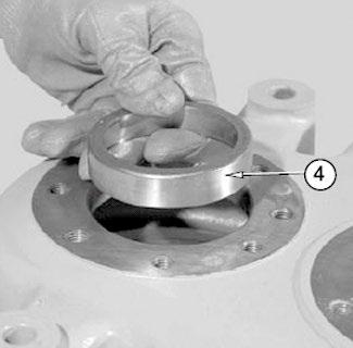
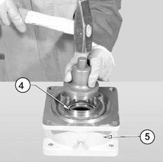
☞ Install bearing race 4 in connection housing 5

NOTE: If there is no response to click on the link above, please download the PDF document first and then clickonit.
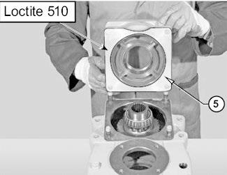
☞ Place connection housing 5 on the gearbox housing with Loctite 510
☞ Tighten fastening screws 9 to 140 Nm
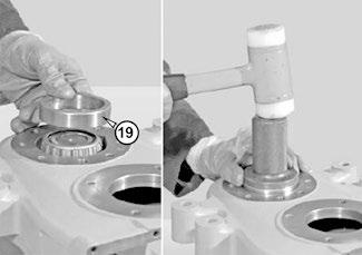
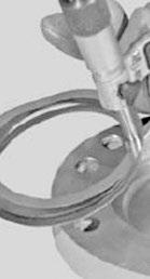
☞ Install outer ring 19
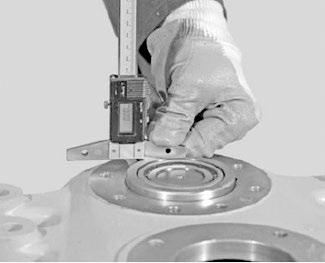
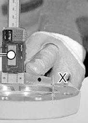
☞ Determine measure Y
➥ Outer ring to contact surface
S 1 = X – Y + 0.1 mm
Axles/differential lock
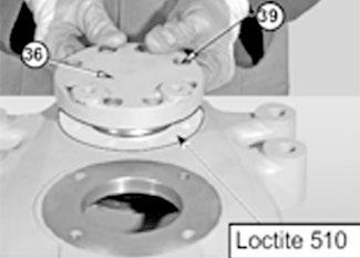
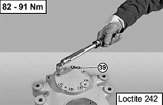
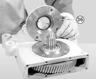
☞ Install cover 36 and fastening screws 39 with Loctite 510
☞ Tighten screws 39 to 90 Nm
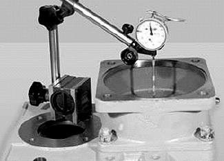
☞ Check bearing for firm position
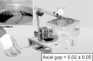
☞ Position a dial gauge
☞ Check 0.02 mm – 0.05 mm bearing play with a lever
☞ Install gear 37
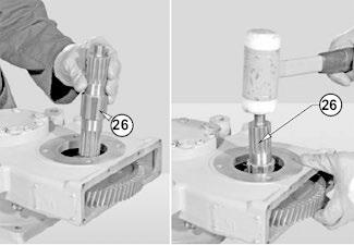
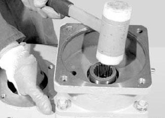
☞ Install shaft 26 with a plastic hammer
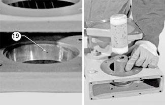
☞ Heat inner ring 19 and install it onto shaft 26
☞ Install outer ring 19
☞ Turn over the gearbox
☞ Install spacer washers 17
☞ Heat the inner ring of bearing 19 to 100 °C and install it
☞ Install outer ring 19