

Previous Screen
Product: BACKHOE LOADER
Model: 420F2 BACKHOE LOADER NSB
Configuration: 420F2 ADL (Air Deployable Loader) NSB00001-UP (MACHINE) POWERED BY 3054C Engine
Disassembly and Assembly
416F2, 420F2 IT, 420F2 ST, 422F2, 428F2, 430F2 IT, 430F2 ST, 432F2, 434F2 and 444F2 Backhoe Loaders Engine Supplement
Media Number -UENR6152-01
Engine - Remove
SMCS - 1000-011
Removal Procedure
Table 1
Required Tools
Tool Part Number Part Description Qty
A 1U-7505 Hydraulic Jack 1
B 6V-3145 Load Leveling Beam 1
Start By:
a. Remove hood.
b. Remove side panels.
c. Remove air cleaner.
d. Remove muffler.
1. Drain the coolant. Refer to Operations and Maintenance Manual, "Cooling System Coolant (ELC) - Change" for the correct draining procedure.
2. Drain the engine oil. Refer to Operations and Maintenance Manual , "Engine Oil and FilterChange" for the correct draining procedures.
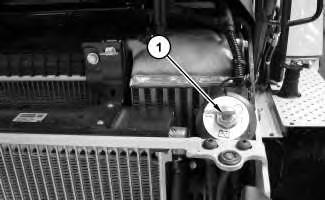
Illustration 1
3. Turn battery disconnect switch (1) to the OFF position.
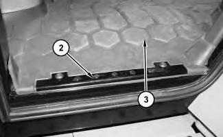
Illustration 2
4. Remove plate (2) and floor mat (3).
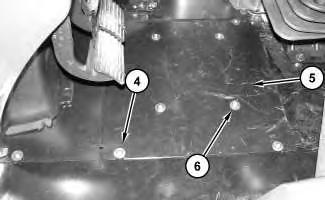
Illustration 3
g03797205
5. Remove bolts (4). Lift plate assembly (5) and secure in rear notches. Do not remove bolts (6).
4
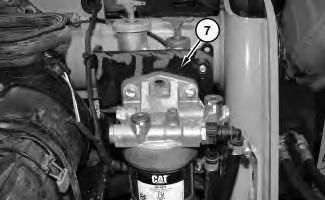
Reposition fuel filter assembly (7) out of the way.
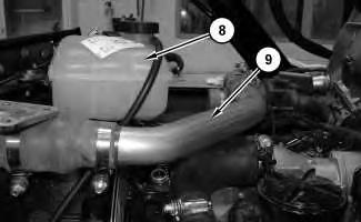
Illustration 5
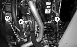
Illustration 6
7. Remove coolant tank assembly (8). Remove tube (9). Remove hoses (10) and (11). Remove tube (12).
7
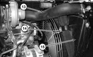
8. Remove hose (13). Remove fan guard (14). Remove fan shroud (15).
8
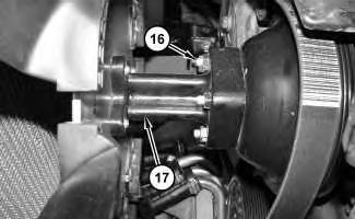
9. Remove nuts (16). Remove fan and hub assembly (17).
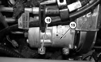
Illustration 9
10. Remove bolts (18) and reposition air condition compressor (19) to the side.
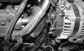
Illustration 10
g03849221
11. Disconnect harness assemblies (20) from the alternator.
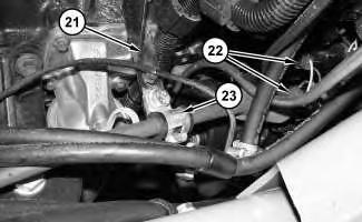
Illustration 11
g03849240
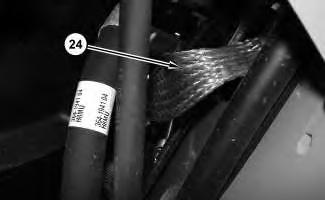
Illustration 12
g03849251
12. Disconnect harness assemblies (21) from the electric starting motor. Disconnect clips (22) from bracket (23). Disconnect ground strap (24).
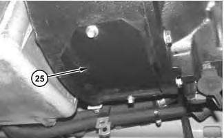
Illustration 13
13. Remove cover (25).
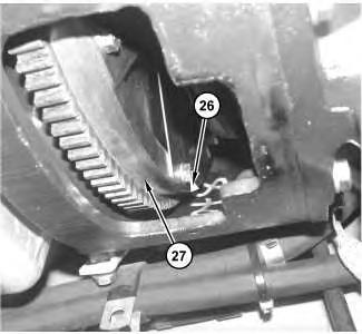
Illustration 14
14. Remove bolts (26) from flywheel (27).
Note: Rotate the engine manually in order to access all bolts (26).
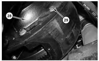
Illustration 15
15. Remove bolts (29) from bell housing (28).
g03849484
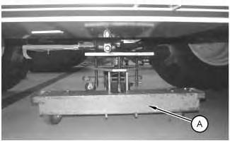
Illustration 16
16. Install Tooling (A) under transmission.
g02997457
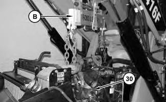
Illustration 17
g03849495
17. Install Tooling (B) and a suitable lifting device. The weight of engine (30) is approximately 544 kg (1200 lb)
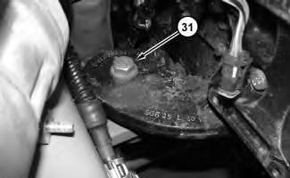
18. Remove engine mounting bolts (31). Repeat on opposite side.
19. Remove engine (30).
Copyright 1993 - 2019 Caterpillar Inc. All Rights Reserved. Private Network For SIS Licensees. Thu Nov 28 23:53:22 UTC+0800 2019
Previous Screen
Product: BACKHOE LOADER
Model: 420F2 BACKHOE LOADER NSB
Configuration: 420F2 ADL (Air Deployable Loader) NSB00001-UP (MACHINE) POWERED BY 3054C Engine
Disassembly and Assembly
416F2, 420F2 IT, 420F2 ST, 422F2, 428F2, 430F2 IT, 430F2 ST, 432F2, 434F2 and 444F2 Backhoe Loaders Engine Supplement
Media Number -UENR6152-01
Engine - Install
SMCS - 1000-012
Installation Procedure
Table 1
Required Tools
Tool Part Number Part Description Qty
A 1U-7505 Hydraulic Jack 1
B 6V-3145 Load Leveling Beam 1
Illustration 1
1. Attach Tooling (B) and a suitable lifting device to engine (30). The weight of engine (30) is approximately 544kg (1200 lb). Use Tooling (B) and the suitable lifting device to position engine (30) into the machine.
2
Illustration 3
2. Align bell housing (28) to the engine and install bolts (29).
3. Rotate the engine and install bolts (26) in order to connect flywheel (27) to the torque converter.
Illustration 4
4. Install engine mounting bolts (31). Repeat on opposite side.
Illustration 5
5. Install access panel (25).
Illustration 6
6. Remove Tooling (A) from the transmission.
7
8
7. Connect ground strap (24). Connect harness assemblies (21) to the electric starting motor. Connect clip (22) to bracket (23).
Illustration 9
g03849221
8. Connect harness assemblies (20) to the alternator.
Illustration 10
g03849219
9. Position air conditioner compressor (19) on the engine and install bolts (18).
14
12. Install tube (12). Install hoses (10) and (11).
13. Install tube (9). Install coolant tank (8).
Illustration 15
14. Install fuel filter assembly (7).
Illustration 16
15. Install plate assembly (5). Install bolts (4).
Note: Do not remove bolts (6).
g03797205
17
16. Position floor mat (3). Position plate (2) and install the bolts . Repeat on the opposite side of the cab.
Illustration 18
g03797183
17. Turn battery disconnect switch (1) to the ON position.
18. Fill the coolant. Refer to Operation and Maintenance Manual, "Cooling System Coolant (ELC) - Change" for the correct filling procedure.
19. Fill the engine oil . Refer to Operation and Maintenance Manual, "Engine Oil and FilterChange" for the correct filling procedure.
End By:
a. Install air cleaner.
b. Install muffler.
c. Install hood assembly.
d. Install side panels.
Previous Screen
Product: BACKHOE LOADER
Model: 420F2 BACKHOE LOADER NSB
Configuration: 420F2 ADL (Air Deployable Loader) NSB00001-UP (MACHINE) POWERED BY 3054C Engine
Disassembly and Assembly
3054C Engines for Caterpillar Built Machines
Media Number -SENR5069-18 Publication Date -01/05/2015 Date Updated -19/09/2018
Fuel Priming Pump and Fuel Filter Base - Remove and Install
SMCS - 1258-010; 1260-010; 1261-010-SE; 1262-010
Removal Procedure
Table 1
Required Tools(1)
i02289796
9U-7069 Cap 3 9U-7067 Cap 3 (1) SERVICE DATA: TOOLING (ZZ) WILL NOT BE IDENTIFIED IN PHOTOGRAPHS IN THE REMOVAL OR THE INSTALLATION. THIS TOOLING IS SHOWN IN ORDER TO ASSIST THE EXPERIENCED SERVICEMAN.
Start By:
a. Remove the assembly of the filter case and the fuel filter element. Refer to this Disassembly and Assembly Manual, "Fuel Filter Base - Remove and Install".
Note: Put identification marks on all fuel hose assemblies and on all tube assemblies for installation purposes. After being disconnected, plug all fuel hose assemblies and plug all tube assemblies. This helps prevent fluid loss, and this helps to keep contaminants from entering the system.
NOTICE
Keep all parts clean from contaminants. Contaminants may cause rapid wear and shortened component life.
NOTICE
Care must be taken to ensure that fluids are contained during performance of inspection, maintenance, testing, adjusting, and repair of the product. Be prepared to collect the fluid with suitable containers before opening any compartment or disassembling any component containing fluids.
Refer to Special Publication, NENG2500, "Dealer Service Tool Catalog" for tools and supplies suitable to collect and contain fluids on Cat products.
Dispose of all fluids according to local regulations and mandates.
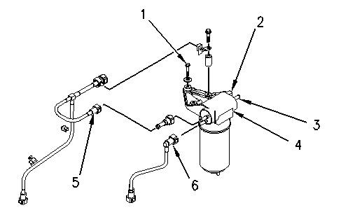
Illustration 1 g00952432
Typical example
1. Disconnect the tube assembly (5). Disconnect the tube assembly (6). Install dust covers onto the connectors for the fuel priming pump.
2. Disconnect the fuel return line from the connector (3). Install a dust cover to the connector (3).
3. Disconnect the harness assembly from the connector (2).
4. Support the fuel priming pump. Remove the three setscrews (1) and discard the rubber washers. Remove the fuel priming pump (4).
Thanks very much for your reading,
Want to get more information,
Please click here, Then get the complete manual

NOTE:
If there is no response to click on the link above, please download the PDF document first, and then click on it.