

Previous Screen
Product: EXCAVATOR
Model: 336D2 L EXCAVATOR LAH
Configuration: 336D2 L Excavators LAH00001-UP (MACHINE) POWERED BY C9 Engine
Disassembly and Assembly
336D 2L and 340D 2L Excavators Machine Systems Media
Travel Motor - Disassemble
SMCS - 4351-015
Disassembly Procedure
i06605028
Start By:
Remove the travel motor.
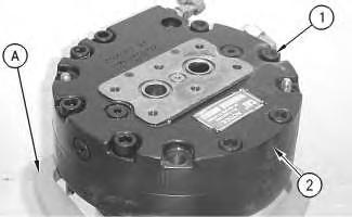
Fasten the travel motor in Tooling (A) in a vertical position. The weight of the travel motor is approximately 88 kg (195 lb).
2. Put an alignment mark across the head and the body of the travel motor for assembly purposes. The head must be reinstalled in the heads original position on the body of the travel motor.
Personal injury can result from being struck by parts propelled by a released spring force.
Make sure to wear all necessary protective equipment.
Follow the recommended procedure and use all recommended tooling to release the spring force.
Note: During the removal of head (2) from the travel motor, be careful not to damage the mating surfaces of the components.
3. Remove bolts (1).
4. Remove head (2) from the body of the travel motor.
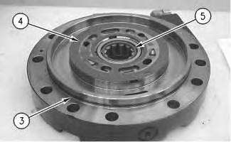
Illustration 2 g00887302
5. Remove O-ring seal (3), port plate (4), and bearing (5).
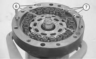
Illustration 3
g00887311
6. Remove O-ring seals (6). Remove springs (7).
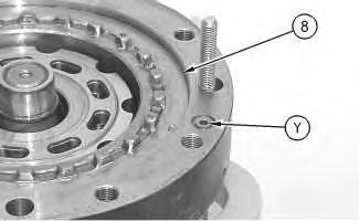
Illustration 4
g00887331
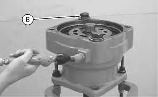
Illustration 5 g00890074 Example of the use of Tooling (B).
7. Place a shop towel over brake piston (8). Retain brake piston (8) with Tooling (B). Apply approximately 525 kPa (75 psi) of shop air pressure to brake release Port (Y). Make sure that the shop air pressure is free of water. Brake piston (8) will move up the piston guide, and out of the piston guide. Remove brake piston (8) from the body of the travel motor.
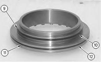
Illustration 6
g00887336
8. Remove seal (9) and backup ring (10) from the brake piston.
9. Remove seal (11) and backup ring (12) from the brake piston.
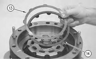
Illustration 7
g00887355
10. Remove plates (13) and friction discs (14).
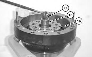
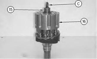
Illustration 9
g00887405
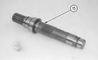
Illustration 10
g00887424
11. Install Tooling (C) into shaft (15). Use a prybar to remove the rotating assembly (16) from the housing.
12. Remove Tooling (C) from shaft (15).
13. Remove shaft (15) from rotating assembly (16).
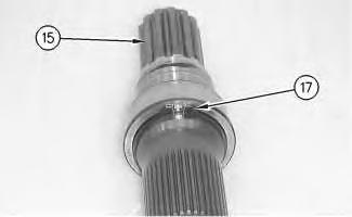
Illustration 11
g00887426
14. Use Tooling (D) to remove retaining ring (17) from shaft (15).
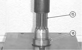
Illustration 12
g00887445
15. Use a suitable press to remove bearing race (18) from shaft (15).
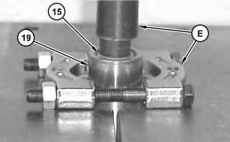
Illustration 13
g03870797
16. Rotate shaft (15). Use a suitable press and Tooling (E) to remove bearing race (19) from shaft (15).
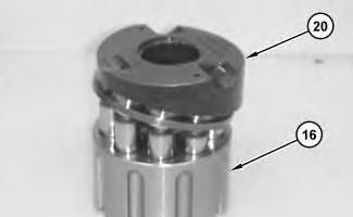
Illustration 14
g03870686
17. Remove cam plate (20) from barrel assembly (16).
15
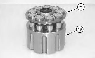
18. Remove piston assemblies and retainer plate (21) from barrel assembly (16).
Note: Place marks on the pistons and the barrel assembly. The pistons must be returned to the original position.
16
g03870760
Personal injury can result from being struck by parts propelled by a released spring force.
Make sure to wear all necessary protective equipment.
Follow the recommended procedure and use all recommended tooling to release the spring force.
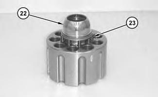
19. Remove ball (22) and springs (23).
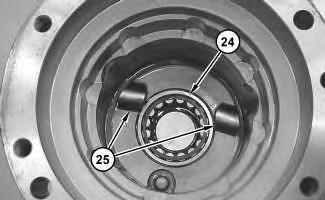
Illustration 17
20. Remove bearing (24).
21. Remove keys (25) and locating pins (not shown) from the body of the travel motor.
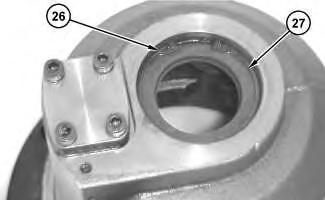
Illustration 18
22. Rotate the housing. Use Tooling (F) to remove retaining ring (26).
23. Remove lip seal (27).
19
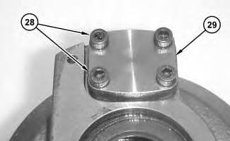
24. Remove bolts (28) and cover (29).
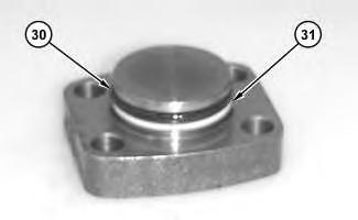
Illustration 20
25. Remove seal (30) and backup ring (31).
g03870779
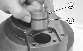
Illustration 21
g03870780
26. Remove piston actuator (32) and seal (33).
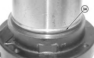
Illustration 22
g03870784
27. Remove O-ring seal (34) from the housing of the travel motor.
Previous Screen
Product: EXCAVATOR
Model: 336D2 L EXCAVATOR LAH
Configuration: 336D2 L Excavators LAH00001-UP (MACHINE) POWERED BY C9 Engine
Disassembly and Assembly
336D 2L and 340D 2L Excavators Machine Systems Media
Travel Motor - Disassemble
SMCS - 4351-015
Disassembly Procedure
Start By:
Remove travel motor.
NOTICE
Care must be taken to ensure that fluids are contained during performance of inspection, maintenance, testing, adjusting, and repair of the product. Be prepared to collect the fluid with suitable containers before opening any compartment or disassembling any component containing fluids.
i07195340
Refer to Special Publication, NENG2500, "Dealer Service Tool Catalog" for tools and supplies suitable to collect and contain fluids on Cat® products.
Dispose of all fluids according to local regulations and mandates.
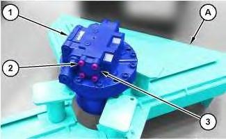
1. Fasten travel motor (1) in a vertical position on Tooling (A). The weight of travel motor (1) is approximately 82 kg (180 lb).
Personal injury can result from being struck by parts propelled by a released spring force.
Make sure to wear all necessary protective equipment.
Follow the recommended procedure and use all recommended tooling to release the spring force.
2. Remove bolts (2) and cap (3).
Personal injury can result from being struck by parts propelled by a released spring force.
Make sure to wear all necessary protective equipment.
Follow the recommended procedure and use all recommended tooling to release the spring force.
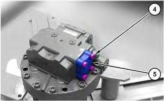
Illustration 2
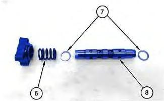
Illustration 3
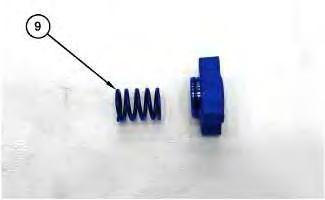
Illustration 4
3. Remove bolts (4) and cap (5).
g06249325
4. Remove spring (6), spring (9), spool assembly (8), and spring seats (7).
5
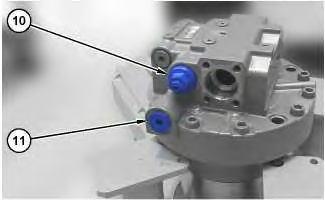
5. Remove plug (11), relief valve (10), and the O-ring seals.
6
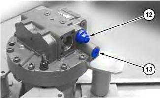
6. Remove plug (13), relief valve (12), and the O-ring seals.
7
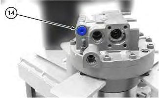
7. Remove plug (14), and the O-ring seal.
8
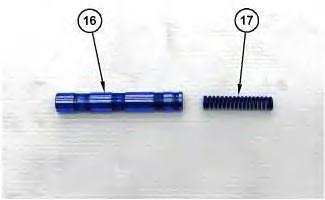
Illustration 9
Personal injury can result from being struck by parts propelled by a released spring force.
Make sure to wear all necessary protective equipment.
Follow the recommended procedure and use all recommended tooling to release the spring force.
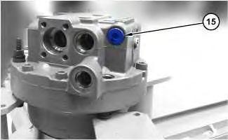
8. Remove plug (15), spool assembly (16), spring (17), and the O-ring seals.
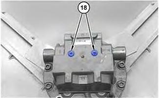
Illustration 10
9. Remove plugs (18) and the O-ring seals.
g06249348

Illustration 11
10. Remove bolts (19).
g06249351
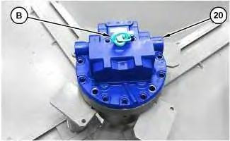
Illustration 12
g06249354
11. Attach Tooling (B) and a suitable lifting device to motor head assembly (20). The weight of motor head assembly (20) is approximately 27 kg (60 lb). Remove motor head assembly (20).
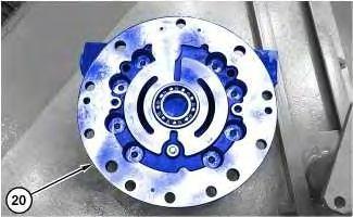
Illustration 13
g06250338
12. Remove the ball bearing that is located on the bottom side of motor head assembly (20).
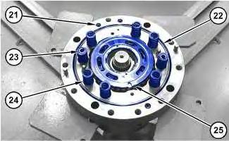
Illustration 14
g06249364
Port plate (25) may still be adhered to the bottom of motor head assembly (20).
13. Remove O-ring seals (21), O-ring seal (22), springs (23), springs (24), and port plate (25).
Note: Note the location of springs (23). They must be installed in the same location during the assembly procedure.
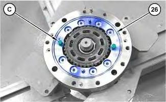
Illustration 15
14. Insert Tooling (C) into piston assembly (26). Use a suitable prying device and Tooling (C) to remove piston assembly (26).
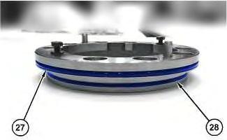
Illustration 16
15. Remove O-ring seal (27) and O-ring seal (28).
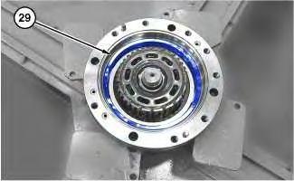
Illustration 17
g06249522
16. Use suitable prying devices to remove guide assembly (29).
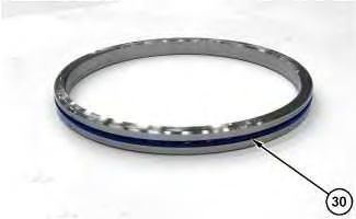
Illustration 18
17. Remove O-ring seal (30).
g06249535
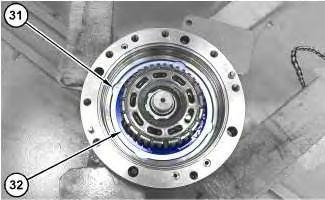
Illustration 19
g06249539
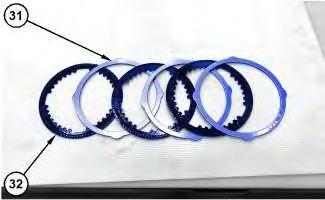
Illustration 20
g06249544
18. Remove separator plates (31) and friction plates (32). Note the alternating order of separator plates (31) and friction plates (32) for assembly purposes.
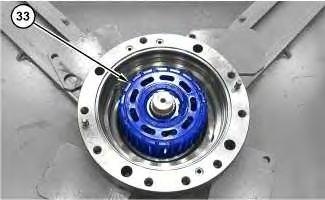
Illustration 21
19. Remove barrel assembly (33).
g06249564
Note: Do not allow the components of barrel assembly (33) to come apart while you remove barrel assembly (33). The components of barrel assembly (33) must be reinstalled into the original positions.
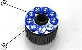
Illustration 22
g06249598
Note: Mark the component locations for assembly purposes before you disassemble the barrel assembly.
20. Remove piston assemblies (34) and retainer (35).
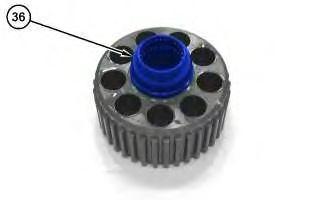
Illustration 23
21. Remove hold down ball (36).
g06249609
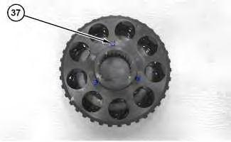
Illustration 24
g06249621
22. Remove dowel pins (37).
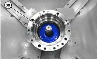
Illustration 25
23. Put location marks on swashplate (38) for assembly purposes. Remove swashplate (38).
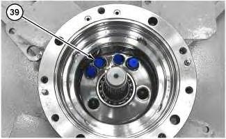
Illustration 26
24. Remove pistons (39) and the balls.
g06249682
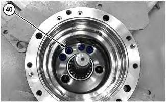
Illustration 27
25. Remove springs (40).
g06249751
Personal injury can result from being struck by parts propelled by a released spring force.
Make sure to wear all necessary protective equipment.
Follow the recommended procedure and use all recommended tooling to release the spring force.
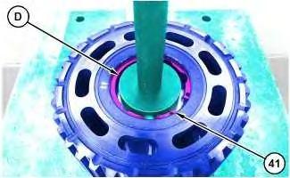
Illustration 28
g06249755
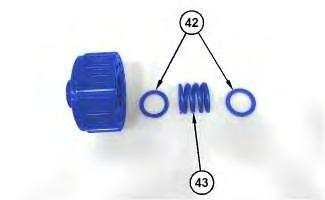
Illustration 29
g06249758
26. Use a suitable press and Tooling (D) to remove snap ring (41), spacers (42), and spring (43).
30
g06249760
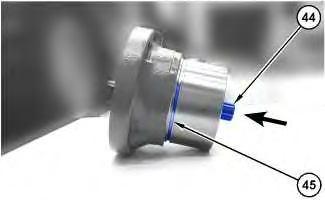
27. Use a soft faced hammer to remove shaft assembly (44). Remove shaft assembly (44) in the direction that is indicated by the arrow.
28. Remove O-ring seal (45).
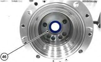
Illustration 31
29. Remove lip seal (46).
g06249762
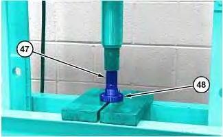
Illustration 32
g06249763
30. Use a suitable press to push shaft (47) out of bearing (48).
Previous Screen
Product: EXCAVATOR
Model: 336D2 L EXCAVATOR LAH
Configuration: 336D2 L Excavators LAH00001-UP (MACHINE) POWERED BY C9 Engine
Disassembly and Assembly
336D 2L and 340D 2L Excavators Machine Systems Media
Travel Motor - Assemble
SMCS - 4351-016
Assembly Procedure
Table 1
i06242093

Illustration 1
1. Install O-ring seal (34) onto the housing of the travel motor.
Illustration 2
g03870780
2. Install seal (33) and piston actuator (32). Lubricate the surfaces of piston actuator (32) with lubricant that is being sealed.
Illustration 3
3. Install backup ring (31) and seal (30).
g03870779
Illustration 4
4. Install cover (29) and bolts (28). Tighten bolts (28) to a torque of 28 ± 7 N·m (248 ± 62 lb in).
Illustration 5
5. Apply Tooling (G) to the mating surface of lip seal (27). Use Tooling (E) in order to install lip seal (27). Lubricate the sealing lip of lip seal (27) with lubricant that is being sealed.
6. Use Tooling (F) in order to install retaining ring (26).
6