John Deere 7610, 7710, 7810 Tractor Operation & Test Manual - TM2030_1
7610, 7710 and 7810 Tractors
Operation and Test
Download Manual
DIAGNOSIS AND TESTS MANUAL
2WD or MFWD models 7610, 7710; 2WD or MFWD - PIN pre x RW - USA models 7810
TM2030 22APR10 (ENGLISH)
For complete service information also see: 7610 7710 and 7810 Tractors Repair TM1651
PowerTech 8.1 L Diesel Engines Base Engine
Alternators and Starting Motors
OEM Engine Accessories
CTM86
CTM77
CTM67
MFWD Axles 1100 and 1150 Series. CTM44
PowerTech 8.1L Diesel Engines Level 9
Electronic Fuel System With Denso High Pressure Common Rail
PowerTech 8.1 L Diesel Engines Mechanical Fuel Systems
PowerTech 4.5L and 6.8L Diesel Engines Mechanical Fuel Systems
PowerTech 6.8L and 8.1L, 6068 and 6081 Diesel Engines (Level 3 Electronic Fuel Systems with Bosch In-Line Pump)
PowerTech 4.5L & 6.8L Diesel Engines Tier 1/Stage I, Tier 2/Stage II, Tier 3/Stage IIIA, Tier 3/Stage IIA Tier 3/Stage III, (Base Engine)
CTM255
CTM243
CTM207
CTM134
CTM104 John Deere Agriculture
Table of contents
FOREWORD
Section 210 - GENERAL
Group 05 - Safety
Group 10 - General References
Group 15 - General References
Section 211 - SERVICE CODE DIAGNOSTICS
Group APC - APC Code Diagnostics
Group CCU - CCU Code Diagnostics
Group ECU - ECU Code Diagnostics
Group HCU - HCU Code Diagnostics
Group JdL - JdL Code Diagnostics
Group LHP - LHP Code Diagnostics
Group PCU - PCU Code Diagnostics
Group PEC - PEC Code Diagnostics
Group RCU - rcu Code Diagnostics
Group SFA - SFA Codes Diagnostics
Group UIC - UIC Code Diagnostics
Section 212 - OBSERVABLE SYMPTOMS
Group 05 - Axles
Group 10 - Brakes
Group 13 - Control Units
Group 15 - Electrical
Group 18 - Engine
Group 20 - Hitch
Group 25 - Heating, Ventilation, and Air Conditioning
Group 30 - Operators Station
Group 40 - Power Take-O
Group 45 - Selective Control Valves
Group 46B - JdLink
Group 50 - Steering
Group 51 - AutoPowr / IVT Transmission
Group 55 - Powershift Transmission
Group 56 - PowerQuad Transmission
Group 57 - AutoQuad II Transmission
Group 70 - Hydraulics
Section 213 - COMPLETE SYSTEM DIAGNOSTICS
Group 40A - North American Lighting
Group 40B - European Lighting
Group 50 - Power Shift Transmission
Group 51 - AutoPowr / IVT Transmission
Group 54 - Autoquad II TransmissionAutoquad II Is A Trademark Of Deere & Company.
Group 55 - PowrQuad Transmission
Group 56 - Drive Systems
Group 56A - Di erential Lock
Group 56B - MFWD
Group 56C - Front PTO
Group 56D - Rear PTO
Group 56E - SFA
Group 60A - Brakes
Group 60B - Steering
Group 70 - Hydraulic System
Group 90 - Air Conditioning System Diagnosis
Section 220 - ENGINES
Group 05 - General Information
Group 10 - Operational Checks
Group 15 - Test And References
Group 20 - Engine System Theory of Operation
Group 25 - Schematics and Diagrams
Section 230 - FUEL AND AIR
Group 15 - Tests and References
Group 20 - Fuel/Air/Cooling System Theory of Operation
Section 240 - ELECTRICAL
Group 05 - General Information
Group 15 - Tests and Adjustments
Group 20 - Theory of Operation
Group 25 - Functional Schematics
Group 35 - Sub-System Diagnostic Schematics
Section 245 - CONTROL UNITS
Group 05 - Codes And Addresses
Group APC - APC References
Group CCU - CCU References
Group ECU - ECU References
Group HCU - HCU References
Group LHP - LHP References
Group PCU - PCU References
Group PEC - PEC References
Group RCU - rcu References
Group SFA - SFA References
Group UIC - UIC References
Section 246B - AG MANAGEMENT SOLUTIONS (AMS) JDLINK
Group 10A - Accessing Diagnostic Addresses and Codes
Group 10B - Diagnostic Trouble Codes
Group 10C - Diagnostic Addresses
Group 15A - JDLINK Machine Messenger Diagnostics
Section 250 - POWERSHIFT TRANSMISSION
Group 05 - General References
Group 10 - Operational Checks
Group 15 - Test And Procedure References
Group 20 - POWERSHIFT THEORY OF OPERATION
Group 25 - SCHEMATICS DIAGRAMS AND COMPONENT LOCATIONS
Section 251 - AUTOPOWR / IVTIVT IS A TRADEMARK OF DEERE & COMPANY TRANSMISSION
Group 05 - General References
Group 10 - Operational Checks
Group 15 - Test And Procedure References
Group 20 - AutoPowr / IVT Theory of Operation
Group 25 - Schematics Diagrams And Component Locations
Section 254 - AUTOQUAD II TRANSMISSION
Group 05 - General References
Group 10 - Operational And Preliminary Checks
Group 15 - Test And Adjustments
Group 20 - AutoQuad Theory Of Operation
Group 25 - SCHEMATICS DIAGRAMS AND COMPONENT LOCATIONS
Section 255 - POWRQUAD TRANSMISSION
Group 05 - General References
Group 10 - Operational Checks
Group 15 - Test And Adjustments
Group 20 - PowrQuad Theory Of Operation
Group 25 - SCHEMATICS DIAGRAMS AND COMPONENT LOCATIONS
Section 256 - DRIVE SYSTEMS
Group 10 - OPERATIONAL CHECKS
Group 15 - TEST REFERENCES
Group 20 - Theory Of Operation
Group 25 - SCHEMATICS DIAGRAMS AND COMPONENT LOCATIONS
Section 260 - STEERING AND BRAKES
Group 15 - Tests and Adjustments
Group 20 - STEERING AND BRAKES THEORY OF OPERATION
Group 25 - SCHEMATICS DIAGRAMS AND COMPONENT LOCATIONS
Section 270 - HYDRAULICS
Group 05 - GENERAL REFERENCES
Group 10 - OPERATIONAL AND PRELIMINARY CHECKS
Group 15 - TEST AND PROCEDURE REFERENCES
Group 20 - HYDRAULIC SYSTEM THEORY OF OPERATION
Group 25 - SCHEMATICS DIAGRAMS AND COMPONENT LOCATIONS
Section 290 - OPERATOR STATION
Group 10 - Operational Checks
Group 15 - Air Conditioning System References
Group 20 - Theory of Operation
Group 25 - Schematics, Diagrams and Component Locations
Section 299 - SERVICE TOOLS
Group 05 - Dealer Fabricated Tools
Group 10 - Service Test Kit Listing
Foreword
This manual is written for an experienced technician. Essential tools required in performing certain service work are identi ed in this manual and are recommended for use.
Live with safety: Read the safety messages in the introduction of this manual and the cautions presented throughout the text of the manual.
CAUTION:
This is the safety-alert symbol. When you see this symbol on the machine or in this manual, be alert to the potential for personal injury.
Technical manuals are divided in two parts: repair and operation and tests. Repair sections tell how to repair the components. Operation and tests sections help you identify the majority of routine failures quickly.
Information is organized in groups for the various components requiring service instruction. At the beginning of each group are summary listings of all applicable essential tools, service equipment and tools, other materials needed to do the job, service parts kits, speci cations, wear tolerances, and torque values.
Technical Manuals are concise guides for speci c machines. They are on-the-job guides containing only the vital information needed for diagnosis, analysis, testing, and repair.
Fundamental service information is available from other sources covering basic theory of operation, fundamentals of troubleshooting, general maintenance, and basic type of failures and their causes.
APC 033- APC Sensor Supply Voltage Low
03
The APC sensing less than 4V supply being provided to the Clutch Enable, Park Brake, and Transmission Pump Pressure Sensors.
Service Code Diagnosis
Alarm Level: Information, Read Operator s Manual
NOTE:
Additional References:
APC Theory of Operation (See Reference 245-APC-200 ).
IVT Transmission Theory of Operation Reference Listing (See Reference 251-20-001 ).
Functional Schematics Listing (See Reference 240-25-001 ).
General References List (See Reference 210-10-002 ).
( 1 ) Preliminary Check
Action:
No preliminary checks required for this code.
Result:
YES: GO TO (2)
( 2 ) Verify Code
Action:
Recall, record and clear codes.
NOTE:
If using SERVICE ADVISOR , this procedure can be performed by making a connection to the CCD bus and using the Diagnostic tab to view and clear codes. If connected through SERVICE ADVISOR, DO NOT use manual procedure for accessing codes.
If not connected to the tractor through SERVICE ADVISOR, see Reference 245-05-001 for procedure.
Recall codes again and check for return of this code.
Result:
YES:Code does not return. GO TO (3) .
NO:Code returns. GO TO (4) .
( 3 ) Operational Check
Action:
NOTE:
Remove diagnostic fuse from F10 location before performing the following operational check.
Start tractor and operate.
See if code is stored again.
Result:
YES:Code does not return. Diagnosis complete.
( 4 ) System Check
Action:
No system checks required for this code.
Result:
YES: GO TO (5)
( 5 ) Circuit Check and Speci cation
Action:
AccessAPC Address 18 .
NOTE:
If not connected to the tractor through SERVICE ADVISOR, see Access Control Unit Addresses (Reference 245-05-002 ) for procedure.
APC Address 18
Perform theSensor Supply Voltage Circuit Test (See Reference 245-APC-018 ), to check the following associated components and circuits:
APC Controller (A101)
Cab Harness (W46)
Circuit 591
Circuit 593
NOTE:
See APC Wiring Diagram in Reference 240-35-100 (Wiring Diagram Listing), for test points.
Result:
YES:Perform Operational Check. GO TO (3) .
NO:Repair as necessary. GO TO (2) .
APC 054- Park Brake Previously Failed / May Not Hold
03 Park engaged (hydraulically) and APC code 055 stored.
Service Code Diagnosis
Alarm Level: Information, Park
NOTE:
Additional References:
APC Theory of Operation (See Reference 245-APC-200 ).
IVT Transmission Theory of Operation Reference Listing (See Reference 251-20-001 ).
Functional Schematics Listing (See Reference 240-25-001 ).
General References List (See Reference 210-10-002 ).
( 1 ) Preliminary Check
Action:
No preliminary checks required for this code.
Result:
YES: GO TO (2)
( 2 ) Verify Code
Action:
Recall, record and clear codes.
NOTE:
If using SERVICE ADVISOR , this procedure can be performed by making a connection to the CCD bus and using the Diagnostic tab to view and clear codes. If connected through SERVICE ADVISOR, DO NOT use manual procedure for accessing codes.
If not connected to the tractor through SERVICE ADVISOR, see Reference 245-05-001 for procedure.
Recall codes again and check for return of this code.
NOTE:
Check to see if APC code 054 is stored with APC 055.
Result:
YES:Code does not return. GO TO (3)
NO:Code returns. GO TO (4)
NO:Code returns and code 055 is stored.Perform AutoPowr / IVT System Diagnostic (Reference 213-51 ).
( 3 ) Operational Check
Action:
NOTE:
Remove diagnostic fuse from F10 location before performing the following operational check.
Operate tractor if possible.
Stop tractor and place in park.
Check to see if APC code 054 is stored again.
Result:
YES:Code does not return. Diagnosis complete.
NO:Code returns. GO TO (4)
( 4 ) System Check
Action:
No system check is required for this code.
Result:
YES: GO TO (5)
( 5 ) Circuit Check and Speci cation
Action:
Check resistance across Park Supply Solenoid, and Park Sump Block Solenoid.
Park Supply Solenoid
Park Sump Block Solenoid
PerformAutoPowr / IVT System Diagnosis (Reference 213-51 ), to check the following associated components and circuits:
Park Brake Solenoid (Y45)
Park Sump Block Solenoid (Y46)
Park Supply Solenoid Valve
Park Sump Block Solenoid Valve
Park Supply Inlet Check Valve
Circuit 638
Circuit 050
Circuit 523
Circuit 080
NOTE:
See APC Wiring Diagram in Reference 240-35-100 (Wiring Diagram Listing), for test points.
The APC detects that the transmission output speed is greater than 8000 rpm for longer than 3 seconds.
Service Code Diagnosis
Alarm Level: Warning, Transmission
NOTE:
Additional References:
APC Theory of Operation (See Reference 245-APC-200 ).
IVT Transmission Theory of Operation Reference Listing (See Reference 251-20-001 ).
Functional Schematics Listing (See Reference 240-25-001 ).
General References List (See Reference 210-10-002 ).
( 1 ) Preliminary Check
Action:
Consult with operator to nd out when indicators illuminated / code was stored.
NOTE:
Operating tractor downhill with a heavy rear load may cause the rear di erential to overspeed the transmission output shaft.
Check the following APC addresses for correct con guration of the transmission output shaft pulses per revolution:
Address
.
YES: GO TO (2)
NO:APC Address 58 and / or 59 is con gured incorrectly. Change as necessary. See APC Calibration (Reference 245-APC-001 ) for procedure. GO TO (2)
( 2 ) Verify Code
Action:
Recall, record and clear codes.
NOTE:
If using SERVICE ADVISOR , this procedure can be performed by making a connection to the CCD bus and using the Diagnostic tab to view and clear codes. If connected through SERVICE ADVISOR, DO NOT use manual procedure for accessing codes.
If not connected to the tractor through SERVICE ADVISOR, see Reference 245-05-001 for procedure.
Recall codes again and check for return of this code.
Result:
YES:Code does not return. GO TO (3)
NO:Code returns. GO TO (4)
( 3 ) Operational Check
Action: NOTE:
Remove diagnostic fuse from F10 location before performing the following operational check.
Perform theAutoPowr / IVT System Diagnostic (Reference 213-51 ).
Result:
YES: GO TO (5)
NO:Make repairs as necessary. GO TO (3)
( 5 ) Circuit Check and Speci cation
Action:
No circuit test is required for this code.
Result:
YES:Clear codes. GO TO (3)
APC 068- Hydro Fixed Unit Speed Sensor Circuit Fault
03
The APC receiving a hydro xed unit speed signal that is either greater than or less than 50 rpm of what the APC internally calculated hydro xed unit speed should be during operation.
Service Code Diagnosis
Alarm Level: Information, Read Operator s Manual
NOTE:
Additional References:
APC Theory of Operation (See Reference 245-APC-200 ).
IVT Transmission Theory of Operation Reference Listing (See Reference 251-20-001 ).
Functional Schematics Listing (See Reference 240-25-001 ).
General References List (See Reference 210-10-002 ).
( 1 ) Preliminary Check
Action:
Check the following address for the correct con guration for hydro xed unit pulses per revolutions:
AccessAPC Address 39 .
The display should read:
39 046
Result:
YES: GO TO (2) .
NO:APC Address 39 is con gured incorrectly. Change as necessary. See APC Calibration (Reference 245-APC-001 ) for procedure. GO TO (2)
( 2 ) Verify Code
Action:
Recall, record and clear codes.
NOTE:
If using SERVICE ADVISOR , this procedure can be performed by making a connection to the CCD bus and using the Diagnostic tab to view and clear codes. If connected through SERVICE ADVISOR, DO NOT use manual procedure for accessing codes.
If not connected to the tractor through SERVICE ADVISOR, see Reference 245-05-001 for procedure.
Recall codes again and check for return of this code.
Result:
YES:Code does not return. GO TO (3) .
NO:Code returns. GO TO (4)
3 ) Operational Check
Action:
NOTE:
Remove diagnostic fuse from F10 location before performing the following operational check.
Start tractor and operate.
Check for code return.
Result:
YES:Code does not return. Diagnosis complete.
NO:Code returns. GO TO (4)
( 4 ) System Check
Action:
No System Checks required for this code.
Result:
YES: GO TO (5)
( 5 ) Circuit Check and Speci cation
Action:
AccessAPC Address 06 .
NOTE:
If not connected to the tractor through SERVICE ADVISOR, see Access Control Unit Addresses (Reference 245-05-002 ) for procedure.
APC Address 06
Perform theHydro Fixed Unit Speed Sensor Circuit Test (Reference 245-APC-006 ), to check the following associated components and circuits:
Sensor (B41)
APC Controller (A101)
Circuit 609 Circuit 050
NOTE:
See APC Wiring Diagram in Reference 240-35-100 (Wiring Diagram Listing), for test points.
APC 069- Carrier Speed Sensor Circuit Fault
03
The APC receiving a carrier speed signal that is either greater than or less than 50 rpm of what the APC internally calculated carrier speed should be during operation.
Service Code Diagnosis
Alarm Level: Information, Read Operator s Manual
NOTE:
Additional References:
APC Theory of Operation (See Reference 245-APC-200 ).
IVT Transmission Theory of Operation Reference Listing (See Reference 251-20-001 ).
Functional Schematics Listing (See Reference 240-25-001 ).
General References List (See Reference 210-10-002 ).
( 1 ) Preliminary Check
Action:
Check the following address for the correct con guration for carrier pulses per revolution:
AccessAPC Address 38 .
The display should read: 38 048
Result:
YES: GO TO (2) .
NO:APC Address 38 is con gured incorrectly. Change as necessary. See APC Calibration (Reference 245-APC-001 ) for procedure. GO TO (2)
( 2 ) Verify Code
Action:
Recall, record and clear codes.
NOTE:
If using SERVICE ADVISOR , this procedure can be performed by making a connection to the CCD bus and using the Diagnostic tab to view and clear codes. If connected through SERVICE ADVISOR, DO NOT use manual procedure for accessing codes.
If not connected to the tractor through SERVICE ADVISOR, see Reference 245-05-001 for procedure.
Recall codes again and check for return of this code.
Result:
YES:Code does not return. GO TO (3) .
NO:Code returns. GO TO (4)
Action: NOTE:
Remove diagnostic fuse from F10 location before performing the following operational check.
Start and operate tractor under no load.
Check to see if APC code 069 is stored under no load.
Restart tractor and operate under load.
Check for transmission slippage.
Check to see if APC code 069 is stored under load.
Result:
YES:Code does not return. Diagnosis complete.
NO:Code returns. GO TO (4)
( 4 ) System Check
Action:
No system check is required for this code.
Result:
YES: GO TO (5)
( 5 ) Circuit Check and Speci cation
Action:
AccessAPC Address 05 . NOTE:
If not connected to the tractor through SERVICE ADVISOR, see Access Control Unit Addresses (Reference 245-05-002 ) for procedure.
APC Address 05
AccessAPC Address 05 and perform theCarrier Speed Sensor Circuit Test (Reference 245-APC-005 ), to check the following associated components and circuits:
Sensor (B42)
APC Controller (A101)
Cab Harness (W46)
Transmission Harness (W45)
NOTE:
See APC Wiring Diagram in Reference 240-35-100 (Wiring Diagram Listing), for test points.
Result:
YES:Perform Operational Check. GO TO (3)
NO:Repair as necessary. GO TO (2)
070- ECU Power Level Invalid
The APC receiving a power level di erent from original power level for ECU power level (during operation). Low idle will be commanded until shutdown.
Service Code Diagnosis
Alarm Level: Information, Engine
NOTE:
Additional References:
APC Theory of Operation (See Reference 245-APC-200 ).
IVT Transmission Theory of Operation Reference Listing (See Reference 251-20-001 ).
Functional Schematics Listing (See Reference 240-25-001 ).
General References List (See Reference 210-10-002 ).
( 1 ) Preliminary Check
Action:
Visually inspect the ECU connector (located beneath the right hand side of seat).
Check to ensure that CAN circuits to ECU connector, and / or pins are not damaged or disconnected.
AccessECU Address 22 . The
NOTE:
See ECU Wiring Diagram in Reference 240-35-100 (Wiring Diagram Listing), for test points.
Result:
YES: GO TO (2) NO:Repair or calibrate as necessary. GO TO (3)
( 2 ) Verify Code
Action:
Recall, record and clear codes.
NOTE:
If using SERVICE ADVISOR , this procedure can be performed by making a connection to the CCD bus and using the Diagnostic tab to view and clear codes. If connected through SERVICE ADVISOR, DO NOT use manual procedure for accessing codes.
If not connected to the tractor through SERVICE ADVISOR, see Reference 245-05-001 for procedure.
Recall codes again and check for return of this code.
Result:
YES:Code does not return. GO TO (3)
NO:Code returns. GO TO (4)
( 3 ) Operational Check
Action: NOTE:
Remove diagnostic fuse from F10 location before performing the following operational check.
Attempt to start and operate tractor.
Check to see if APC code 070 is stored again.
Result:
YES:Code does not return. Diagnosis complete.
NO:Code returns. GO TO (4)
( 4 ) System Test
Action:
Perform theCAN Bus Diagnosis AutoPowr / IVT (Reference 245-05-007 ).
Result:
YES:CAN Bus Diagnosis did not reveal any malfunction(s). Replace and calibrate UIC. See UIC Calibration (Reference 245UIC-001 ).
NO:CAN Bus Diagnosis reveals a malfunction. Repair as necessary. GO TO (2)
( 5 ) Circuit Check and Speci cation
Action:
No circuit test is required for this code.
Result:
YES:Clear codes. GO TO (2) .
APC 071- ECU Vehicle Level Invalid
03
The APC receiving a vehicle level di erent from original vehicle level. Low idle will be commanded until shutdown.
Service Code Diagnosis
Alarm Level: Information, Engine
NOTE:
Additional References:
APC Theory of Operation (See Reference 245-APC-200 ).
IVT Transmission Theory of Operation Reference Listing (See Reference 251-20-001 ).
Functional Schematics Listing (See Reference 240-25-001 ).
General References List (See Reference 210-10-002 ).
( 1 ) Preliminary Check
Action:
Visually inspect the ECU connector (located beneath the right hand side of seat).
Check to ensure that ECU connector, and / or pins are not damaged or disconnected.
AccessECU Address 24 . The
level calibration should read:
AccessECU Address 25 . The
NOTE:
See ECU Wiring Diagram in Reference 240-35-100 (Wiring Diagram Listing), for test points.
Result:
YES: GO TO (2)
NO:Repair or calibrate as necessary. GO TO (2)
( 2 ) Verify Code
Action:
Recall, record and clear codes.
NOTE:
If using SERVICE ADVISOR , this procedure can be performed by making a connection to the CCD bus and using the Diagnostic tab to view and clear codes. If connected through SERVICE ADVISOR, DO NOT use manual procedure for accessing codes.
If not connected to the tractor through SERVICE ADVISOR, see Reference 245-05-001 for procedure.
Recall codes again and check for return of this code.
Result:
YES:Code does not return. GO TO (3)
NO:Code returns. GO TO (4)
( 3 ) Operational Check
Action: NOTE:
Remove diagnostic fuse from F10 location before performing the following operational check.
Attempt to start and operate tractor.
Check to see if APC code 071 is stored again.
Result:
YES:Code does not return. Diagnosis complete.
NO:Code returns. GO TO (4)
( 4 ) System Test
Action:
Perform theCAN Bus Diagnosis AutoPowr / IVT (Reference 245-05-007 ).
Result:
YES:CAN Bus Diagnosis did not reveal any malfunction(s). Replace and calibrate UIC. See UIC Calibration (Reference 245UIC-001 ).
NO:CAN Bus Diagnosis reveals a malfunction. Repair as necessary. GO TO (2)
( 5 ) Circuit Check and Speci cation
Action:
No circuit test is required for this code.
Result:
YES:Clear codes. GO TO (2) .
APC 075- Hydro Fixed Unit Overspeed
03
The APC detects a hydro xed unit speed above 2500 rpm. Amperage to hydro control valve will be reduced until hydro xed unit speed drops below 2450 rpm. The code will clear when hydro speed drops below 2200 rpm.
Service Code Diagnosis
Alarm Level: Warning, Transmission
NOTE:
Additional References:
APC Theory of Operation (See Reference 245-APC-200 ).
IVT Transmission Theory of Operation Reference Listing (See Reference 251-20-001 ).
Functional Schematics Listing (See Reference 240-25-001 ).
General References List (See Reference 210-10-002 ).
( 1 ) Preliminary Check
Action:
Check the following address for the correct con guration for hydro xed unit pulses per revolutions:
AccessAPC Address 39 .
The display should read:
39 046
Result:
YES: GO TO (2) .
NO:APC Address 39 is con gured incorrectly. Change as necessary. See APC Calibration (Reference 245-APC-001 ) for procedure. GO TO (2)
( 2 ) Verify Code
Action:
Recall, record and clear codes.
NOTE:
If using SERVICE ADVISOR , this procedure can be performed by making a connection to the CCD bus and using the Diagnostic tab to view and clear codes. If connected through SERVICE ADVISOR, DO NOT use manual procedure for accessing codes.
If not connected to the tractor through SERVICE ADVISOR, see Reference 245-05-001 for procedure.
Recall codes again and check for return of this code.
Result:
YES:Code does not return. GO TO (3) .
NO:Code returns. GO TO (4)
Action:
NOTE:
Remove diagnostic fuse from F10 location before performing the following operational check.
Start engine operate tractor in all forward and reverse modes.
Recall, Record, and Clear Codes (See Reference 245-05-001 ).
Check to see if APC 075 is stored again.
Result:
YES:Code does not return. Diagnosis complete.
NO:Code returns. GO TO (4)
( 4 ) System Check
Action:
Perform theAutoPowr / IVT System Diagnostic (Reference 213-51 ) to determine the cause of the hydro xed unit overspeed code being generated.
Result:
YES: GO TO (5)
NO:Repair as necessary. Perform Operational Check. GO TO (3)
( 5 ) Circuit Check and Speci cation
Action:
AccessAPC Address 06 .
NOTE:
If not connected to the tractor through SERVICE ADVISOR, see Access Control Unit Addresses (Reference 245-05-002 ) for procedure.
Address 06
Perform theHydro Fixed Unit Speed Sensor Circuit Test (Reference 245-APC-006 ), to check the following associated components and circuits:
Sensor (B41)
APC Controller (A101)
Cab Harness (W46)
Transmission Harness (W45)
Circuit 609
NOTE:
See APC Wiring Diagram in Reference 240-35-100 (Wiring Diagram Listing), for test points.
Result:
YES:Perform Operational Check. GO TO (3)
NO:Repair as necessary. GO TO (2)
APC 077- Park Sump Block Valve Fault
03
The APC calculates a di erential pressure when the park brake is engaged. The park supply solenoid valve is turned o before the park sump block solenoid valve is turned o to see if the sump blocking valve will hold park release pressure from spring engagement of the park element. If the pressure value from when the sump blocking valve is holding o park engagement is less than 75% of the pressure measured when the park supply valve is holding o park engagement, code 077 is stored to indicate a failed sump block valve.
Service Code Diagnosis
Alarm Level: Warning, Park
NOTE:
Additional References:
APC Theory of Operation (See Reference 245-APC-200 ).
IVT Transmission Theory of Operation Reference Listing (See Reference 251-20-001 ).
Functional Schematics Listing (See Reference 240-25-001 ).
General References List (See Reference 210-10-002 ).
( 1 ) Preliminary Check
Action:
No preliminary checks required for this code.
Result:
YES: GO TO (2)
( 2 ) Verify Code
Action:
Recall, record and clear codes.
NOTE:
If using SERVICE ADVISOR , this procedure can be performed by making a connection to the CCD bus and using the Diagnostic tab to view and clear codes. If connected through SERVICE ADVISOR, DO NOT use manual procedure for accessing codes.
If not connected to the tractor through SERVICE ADVISOR, see Reference 245-05-001 for procedure.
Recall codes again and check for return of this code.
Result:
YES:Code does not return. GO TO (3)
NO:Code returns. GO TO (4)
( 3 ) Operational Check
Action:
APC Address 12
Perform thePark Brake Pressure Sensor Circuit Test (See Reference 245-APC-012 ), to check the following associated components and circuits:
Sensor (B39)
Cab Harness (W46)
Transmission Harness (W45)
Circuit 591
Circuit 621
Circuit 593
NOTE:
See APC Wiring Diagram in Reference 240-35-100 (Wiring Diagram Listing), for test points.
Result:
YES:Perform Operational Check. GO TO (3)
NO:Repair as necessary. GO TO (2)
APC 097- Transmission Oil Filter Bypassed < 1500 rpm / Park Not Engaged
03
The APC detecting park pressure is 675 kPa (6.6 bar) (98 psi) below pump pressure while engine is below 1500 rpm, and transmission is not in park. Low idle will be commanded by the APC until power down.
Service Code Diagnosis
Alarm Level: Stop Engine, Transmission Oil Filter
NOTE:
Additional References:
APC Theory of Operation (See Reference 245-APC-200 ).
IVT Transmission Theory of Operation Reference Listing (See Reference 251-20-001 ).
Functional Schematics Listing (See Reference 240-25-001 ).
General References List (See Reference 210-10-002 ).
( 1 ) Preliminary Check
Action:
Check the condition and service interval of the transmission oil and lter.
Result:
YES:Oil and lter are OK. GO TO (2)
NO:Oil and / or lter need to be changed. Change as necessary. GO TO (2)
( 2 ) Verify Code
Action:
Recall, record and clear codes.
NOTE:
If using SERVICE ADVISOR , this procedure can be performed by making a connection to the CCD bus and using the Diagnostic tab to view and clear codes. If connected through SERVICE ADVISOR, DO NOT use manual procedure for accessing codes.
If not connected to the tractor through SERVICE ADVISOR, see Reference 245-05-001 for procedure.
Recall codes again and check for return of this code.
Result:
YES:Code does not return. GO TO (3) .
NO:Code returns. GO TO (4)
( 3 ) Operational Check
Action: NOTE:
Remove diagnostic fuse from F10 location before performing the following operational check.
Hydro Fixed Unit Speed Sensor (B41)
APC Controller (A101)
Circuit 609
Circuit 050
NOTE:
See APC Wiring Diagram in Reference 240-35-100 (Wiring Diagram Listing), for test points.
Result:
YES:Perform Operational Check GO TO (3)
NO:Repair as necessary. GO TO (2)
APC 119- Carrier Speed Low at Start-Up
03
The APC giving full outboard command to the hydro control solenoid, and the carrier speed input to the APC does not come within 250 rpm of the internally calculated expected carrier speed within 25 seconds of startup.
Service Code Diagnosis
Alarm Level: Information, Transmission
NOTE:
Additional References:
APC Theory of Operation (See Reference 245-APC-200 ).
IVT Transmission Theory of Operation Reference Listing (See Reference 251-20-001 ).
Functional Schematics Listing (See Reference 240-25-001 ).
General References List (See Reference 210-10-002 ).
( 1 ) Preliminary Check
Action:
AccessAPC Address 38 .
Display should read: 38 048
NOTE:
The value stored at APC Address 38 is the con guration for the pulses or gear teeth that pass the carrier speed sensor in one revolution. An incorrect value stored at this address will prohibit correct speed calculation.
Check to ensure that the Transmission Enable fuse from the F37 location is not installed at the F41 location.
Result:
YES: GO TO (2) .
NO:Display does not read 048 . Change and save as necessary. (See APC Calibration 245-APC-001 for procedure). GO TO (2) .
( 2 ) Verify Code
Action:
Recall, record and clear codes.
NOTE:
If using SERVICE ADVISOR , this procedure can be performed by making a connection to the CCD bus and using the Diagnostic tab to view and clear codes. If connected through SERVICE ADVISOR, DO NOT use manual procedure for accessing codes.
If not connected to the tractor through SERVICE ADVISOR, see Reference 245-05-001 for procedure.
Recall codes again and check for return of this code.
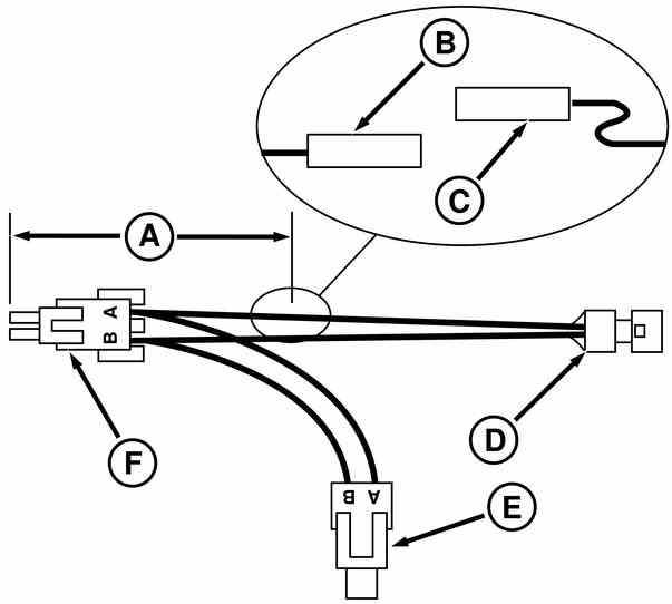
B2 and B3=RE12364 3-Way Weatherpack tower (with seal) with three R78061 pin terminals
Also required:
Nine R78063 seals
Three 200 mm (8 in.) lengths of wire (14 Ga.), of di erent color
Three 150 mm (6 in.) lengths of wire (14 Ga.) to match color of 200 mm (8 in.) wires
Three AR67855 wire tap connectors
DFRW65 Tap-Out Harness (B)
B1=R78054 3-Way Weatherpack shroud with three R78061 pin terminals
B2=RE12364 3-Way Weatherpack tower (with seal) with three R78060 sleeve terminals
B3=RE12364 3-Way Weatherpack tower (with seal) with three R78061 pin terminals
Also required:
Three 200 mm (8 in.) lengths of wire (14 Ga.), of di erent color
Three 150 mm (6 in.) lengths of wire (14 Ga.) to match color of 200 mm (8 in.) wires
Three AR67855 wire tap connectors
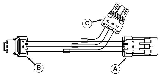
DFRW66 Tap-Out Harness (C)
C1=R78053 2-Way Weatherpack shroud with two R78061 pin terminals
C2=RE12331 2-Way Weatherpack tower (with seal) with two R78060 sleeve terminals
C3=RE12331 2-Way Weatherpack tower (with seal) with two R78061 pin terminals
Also required:
Two 200 mm (8 in.) lengths of wire (14 Ga.), of di erent color
Two 150 mm (6 in.) lengths of wire (14 Ga.), to match color of 200 mm (8 in.) wires
Two AR67855 wire tap connectors
DFRW81 Tap-Out Harness (C)
A1=R78053 2-Way Weatherpack shroud with two R78060 sleeve terminals
A2=RE12363 2-Way Weatherpack tower (with seal) with two R78061 pin terminals
A3=RE12363 2-Way Weatherpack tower (with seal) with two R78061 pin terminals
Also required:
Six R78063 Seals
Two 200 mm (8 in.) lengths of wire (14 Ga.), of di erent color
Two 150 mm (6 in.) lengths of wire (14 Ga.), to match color of 200 mm (8 in.) wires
Two AR67855 wire tap connectors
Reference 299-05-007, DFRW126 Tap-Out Harness
DFRW126 Tap-Out Harness
LEGEND:
A 104 mm (4 in)
B R65597 Male Terminal (W/R77475 Female Connector Body)
C U46662 Female Terminal (W/M43835 Male Connector Body)
D Shift Valve Connector
E Tractor Harness Connector
F Weatherpack Two-Way Tower Connector
FABRICATION: Modify JDG774 Tap-Out Harness as shown (to be able to read current draw) by doing the following.
Measure 104 mm (4 in) (A) from one end of the Weather Pack connector (F) along the wire attached to terminal A . Mark and cut the wire.
Strip insulation approximately 5 mm (3/16 in) from each end of cut wire.
Add a R65597 blade terminal and R77475 female connector body (B) to one end.
Add a U46662 female terminal and M43835 male connector body (C) to the other end.
USE: DFRW126 is used to measure the current draw (in mA), of the power shift transmission analog shift valve solenoids, at di erent steps of valve engagement. Current draw data is used to analyze performance of the electronic portion of the shift valve.
Connect the ammeter in series by attaching meter leads to disconnected male and female terminals (B and C).
NOTE:
Terminals (B and C) must be connected when using the tap-out harness as JDG774 for making voltage readings.
Reference 299-05-008, DFRW133 Tap-Out Harness
DFRW133 Tap-Out Harness
LEGEND:
A 57M7257 3-Way Metri-Pack Shroud Connector
B 57M7255 3-Way Metri-Pack Tower Connecotr
C RE12364 Weatherpack Tower Connector
NOTE:
A 35-Pin CPC bulkhead connector (R77456 Amp No. 206151-1) can be substituted for the above connectors, with the appropriate terminals (R77464 Pin), for use with JT02016 Combine Receptacle Kit.
A One 57M7257 3-Way Metri-Pack shroud connector, three R104919 pin terminals, three 57M7258 seals and a 57M7317 retainer.
B One 57M7255 3-Way Metri-Pack tower connector, three R104846 socket terminals, three 57M7258 seals and a 57M7317 retainer.
C One RE12364 Weatherpack tower connector, three R78061 pin terminals and three R78063 seals
Also required
Three 200 mm (8 in.) lengths of wire (14 Ga.), of di erent color
Three 150 mm (6 in.) lengths of wire (14 Ga.) to match color of 200 mm (8 in.) wires
Three AR67855 wire tap connectors
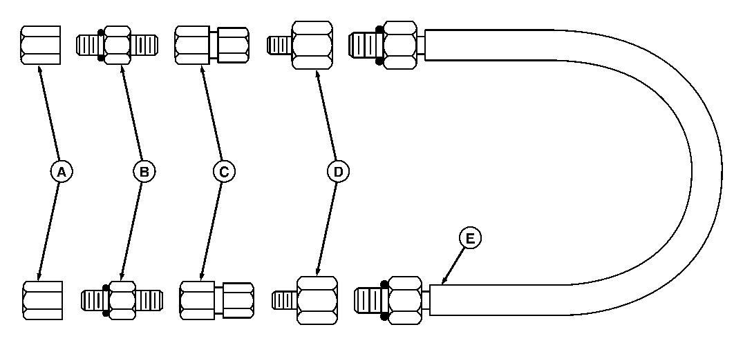
Reference 299-05-009, DFRW123 Bypass Hose
Bypass Hose
LEGEND:
A
B
C
D
JT03032 or R39783 Cap, 9/16-18 JIC
JT03036 or R27095 Union Connector
JT03005 Swivel Adapter
JT03041 or R30816 Adapter
E R36659 Hose
CAUTION:
Must use all components required to ensure proper ID.
Assemble JT03032 or R39783 Cap (9/16-18 JIC) (A), JT03036 or R27095 (9/16-18 (M) JIC, Use R26448 O-ring) adapter (B), JT03005 (9/16-18 (F) JIC x 1/2-14 (F) NPT) (C) and JT03041 or R30816 (1/2-14 (M) NPT x 3/4-16 (F) O-ring) (D) to each end of R36659 hose (SAE-R2, 1/2 in. I.D. x 36 in. length) (E).
This hose assembly is used for hydraulic testing.
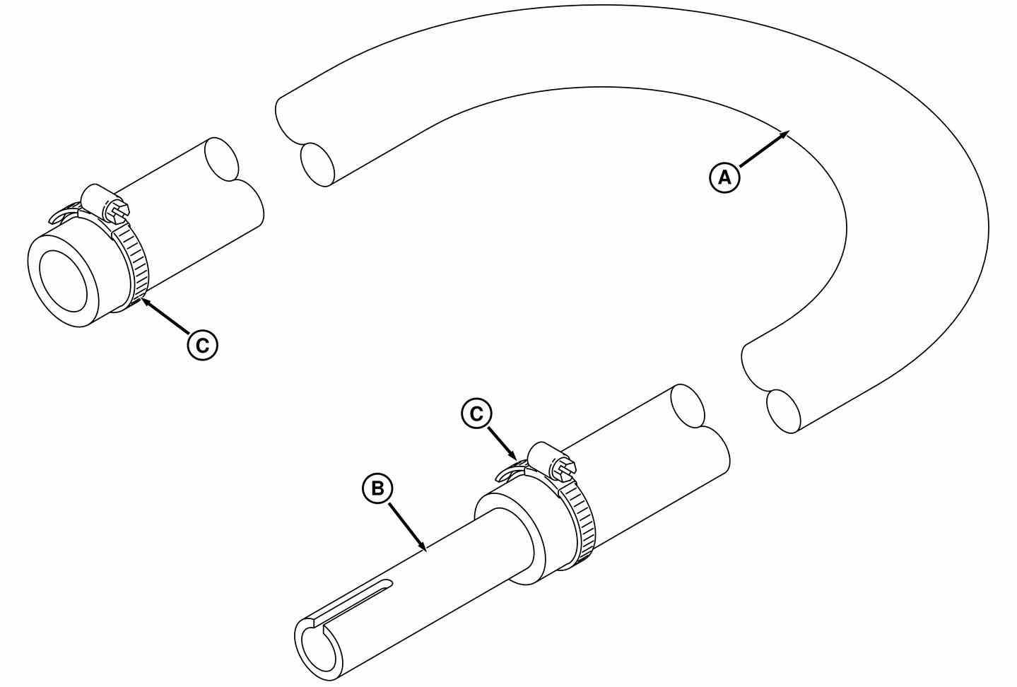
Reference 299-05-010, DFRW145 Leak Test Hose
DFRW145
LEGEND: A 1 I.D. x 60 Long Flexible Hose B 3/4 NPT x 6 Plastic Nipple C (2) 2 Hose Clamps
Cut a 1/4 x 2 1/2 Long Slot in one end of 3/4 NPT x 6 Plastic Nipple (B). Insert other end of nipple 1 1/2 to 2 inches into 1 I.D. x 60 Long Flexible Hose (A) and tighten 2 Hose Clamp (C) around hose and tting. Use other hose clamp as necessary for securing hose.