Service Manual
WX150, WX170 and WX200 wheeled excavators
* Refer to the Schematic Set WX150, WX170, WX200.
* * Consult the engine Service Manual.
Copyright 2003 CNH France S.A. Printed in France CNH Cre 9-53961GBMarch 2003
Table of contents DIVISION/SECTIONSECTION No.REFERENCE No 1GENERAL INFORMATION Safety, general section and standard torque settings......................................1001* Specifications (Wheeled excavators)...............................................................1002* 2ENGINE Removal and installation of the engine............................................................20029-54130GB Removal and installation of the engine WX150 : CGG0228401..., WX170 : CGG0232601..., WX200 : CGG0231801 ..., WX200M : CGG0233301... .................................20029-88230GB Radiator and oil-cooler.....................................................................................20039-53720GB Engine specifications.......................................................................................2401* * Cylinder head and valve assembly..................................................................2415* * Engine block....................................................................................................2425* * Lubrication circuit.............................................................................................2445* * Cooling circuit..................................................................................................2455* * Turbocharger....................................................................................................2465* * Analysis of turbocharger failures......................................................................2565* * 3FUEL SYSTEM Fuel circuit and filter.........................................................................................3410* * CAV injection pump..........................................................................................3411* * BOSCH injection pump....................................................................................3412* * Fuel injector.....................................................................................................3412* * BOSCH ANEROID injection pump...................................................................3416* * 4ELECTRICAL SYSTEM Electrical schematics.......................................................................................4001* Electronic system and troubleshooting............................................................4002* Starter motor....................................................................................................40037-58691GB Alternator.........................................................................................................40047-58701GB 5UNDERCARRIAGE 6DRIVE TRAIN Reduction gear and swing brake Trasmital 705T2...........................................60037-80671GB Reduction gear and swing brake Trasmital 757T2...........................................60037-84141GB Front axle and service brake - CARRARO 638LD and 638FR axle................60049-53250GB Front axle and service brake - CARRARO 652FR axle...................................60049-53260GB Rear axle and service brake - CARRARO 852FR axle....................................60059-53270GB Rear axle and service brake - CARRARO 838LD and 838FR axle.................60059-53290GB Gearbox and parking brake.............................................................................60087-80701GB Twin wheels.....................................................................................................60209-53300GB 7UNDERCARRIAGE HYDRAULICS Hydraulic travel motor......................................................................................70037-80731GB One-piece control valve for travel, stabilizers and dozer blade.......................70319-53620GB Two section control valve for travel, stabilizers and dozer blade.....................70317-84151GB
(WX200)...................................................................70807-79180GB
(WX150-WX170).......................................................70809-53440GB
Cylinders for steering, stabilizers, dozer blade and front axle locking
Cylinders for steering, stabilizers, dozer blade and front axle locking
Thanks very much for your reading, Want to get more information, Please click here, Then get the complete manual
NOTE:
If there is no response to click on the link above, please download the PDF document first,andthen click on it.

* Refer to the Schematic Set WX150, WX170, WX200.
NOTE: CNH France S.A. company reserves the right to modify without prior notice the characteristics and the design of the machine without any obligation to carry out those modifications on machines already sold.
The description of the models shown in this manual has been made using the technical specifications known at the date on which this document was designed.
Cre 9-53961GB Issued 03-03 DIVISION/SECTIONSECTION No.REFERENCE No.
HYDRAULICS Hydraulic inspections, adjustments and schematics (Wheeled excavators)....8001* Hydraulic swivel...............................................................................................80117-80801GB High pressure hydraulic pump (WX170 - WX200)...........................................80209-54020GB High pressure and swing hydraulic pump (WX150).........................................80209-54030GB Hydraulic swing pump 28 cc fixed flow (WX170).............................................80217-27101GB Hydraulic swing pump 45 cc variable flow (WX200)........................................80217-79221GB MARREL attachment control valve..................................................................80317-80822GB REXROTH attachment control valve...............................................................80319-53860GB One-piece swing control valve.........................................................................80337-79241GB Two-piece swing control valve.........................................................................80337-80832GB Swing control valve (Orbitrol)...........................................................................80377-80841GB Hydraulic swing motor and safety and force-feeding block..............................80407-80852GB Hydraulic fan motor..........................................................................................80419-54010GB Attachment and swing control block................................................................80509-53680GB Option control block.........................................................................................80519-53610GB Direction of travel inverter control block...........................................................80537-80290GB Travel control block..........................................................................................80547-80301GB Brake unit.........................................................................................................80609-53570GB Parking brake electro-control valve..................................................................80619-54040GB Electro-control valve block ..............................................................................80719-54120GB Flow cancellation over-pressure selector block...............................................80727-26651GB Electro-control valve block DRE4....................................................................80739-54110GB Attachment cylinders........................................................................................80809-53560GB Safety valves....................................................................................................80817-26641GB 9UPPERSTRUCTURE Upperstructure and turntable...........................................................................90029-53830GB Cab..................................................................................................................90049-53840GB
8UPPERSTRUCTURE
CNH Copyright 2003 CNH France S.A. Printed in France March 2003 Cre 9-54130GB 2002 ENGINE REMOVAL AND INSTALLATION Section 2002
TABLE OF CONTENTS
This symbol is used in this manual to indicate important safety messages. Whenever you see this symbol, carefully read the message that follows, as there is a risk of serious injury.
SPECIFICATIONS
SPECIAL TORQUES
1
2 1
3
TOOLS REQUIRED
4 1 Sling (400 to 600 kg)
5 2 Slings (150 to 200 kg)
6 1 Receptacle (30 litres)
7 1 Plugging shaft - length 100 mm and diameter 27 mm
8 1 Loctite 638
2002-2 Cre 9-54130GB Issued 03-03
SPECIFICATIONS....................................................................................................................................................2 SPECIAL TORQUES................................................................................................................................................2 TOOLS REQUIRED ................................................................................................................................................2 REMOVAL AND INSTALLATION.............................................................................................................................3 CHECKING ELECTRICAL CONNECTIONS ON TEMPERATURE SENSORS ......................................................9
Engine (without hydraulic pump) WX150 model .........................................................................................................................................350 kg WX170-200 model .................................................................................................................................443 kg High pressure hydraulic pump WX150 model ..........100 kg WX170-200 model ..130 kg Upper hood WX150 model ...........................................................................................................................................26 kg WX170-200 model ...................................................................................................................................43 kg Complete cooling circuit WX150 model .....14.5 litres WX170-200 model 20 litres Lubricant and coolant solution......................................................................................................(see section 1002)
Weights:
Engine/hydraulic pump retaining screws.........................................................................................................44 Nm Splined sleeve retaining screws....................................................................................................................120 Nm Shock absorber centring stud retaining screws.............................................................................................220 Nm Engine bracket retaining screws.........................................................................................................217 to 271 Nm
1 Torque wrench (10 to 50 Nm)
Torque
wrench (40 to 200 Nm)
1 Torque wrench (70 to 360 Nm)
Before carrying out any servicing on the machine, perform the following operations in the order shown:
- Park the machine on flat, hard ground.
- Lower the attachment to the ground.
- Shut down the engine and allow it to cool down.
- Place the battery master switch in the "OFF" position and remove the key.
When the machine is operating, the engine and hydraulic pump reach high temperatures. To avoid being burnt by hot metal or scalded by high temperature oil or water, allow the machine to cool down before starting any servicing operation.
Removal and installation
STEP 3
Remove the exhaust silencer outlet pipe.
NOTE: When installing, make sure that the exhaust outlet is oriented rearwards.
STEP 4
Remove the upper hood using suitable lifting equipment.
STEP 5
Remove the side hood, at the walkway end.
STEP 6
Remove the exhaust silencer and its bracket.
STEP 7
(WX150 model)
Remove the hose which connects the turbo-charger to the air filter.
(WX170-200 model)
Remove the hose connecting the air filter to the turbo-charger, disconnect the air filter restriction pressure switch harness (see item (7) Step 11), then remove the air filter.
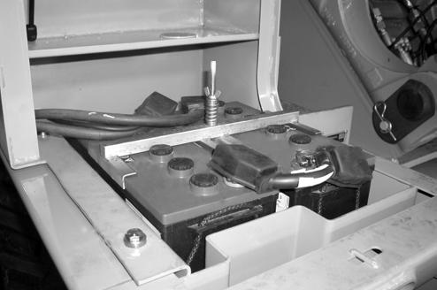
Disconnect the negative cable (1) first, then disconnect the other cables.
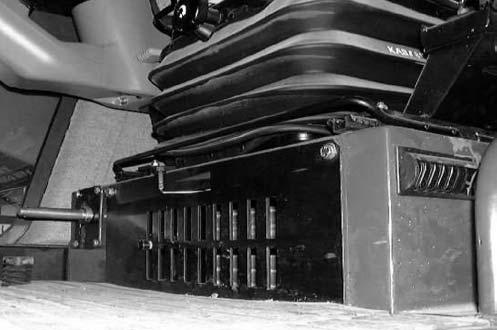
STEP 2
Remove the access panels located under the engine.
2002-3 Cre 9-54130GB Issued 03-03
STEP 1 WX150 model
WX170-200 model
CD02J005
1
PG03613
STEP 11


2002-4 Cre 9-54130GB Issued 03-03
STEP 8 WX150 model
Disconnect the connector (1) from the speed detector (2).
STEP 9
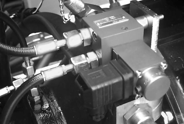
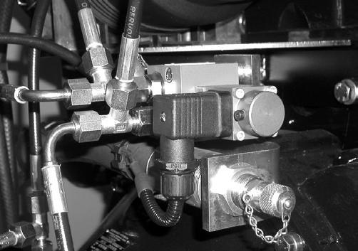
Disconnect the electrical supply (1) from the proportional pressure reduction valve DRE4 (2).
STEP 10
Disconnect the electrical supply (1) from the proportional pressure reduction valve DRE4 (2) and the connector (3) from the speed detector (4).
2 1
CD96D002
CD96A00
CDCD02J006
4 3 2 1
CD96A008
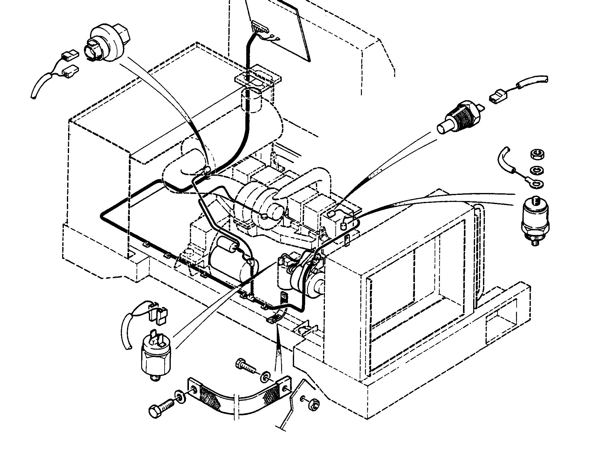
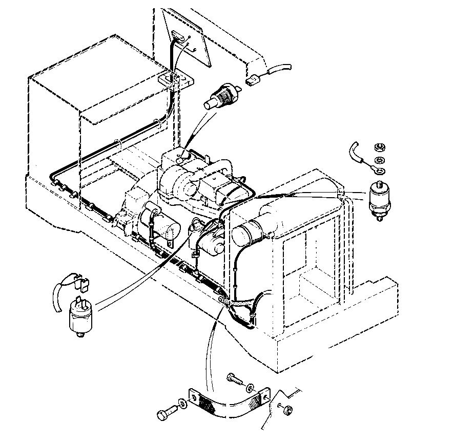
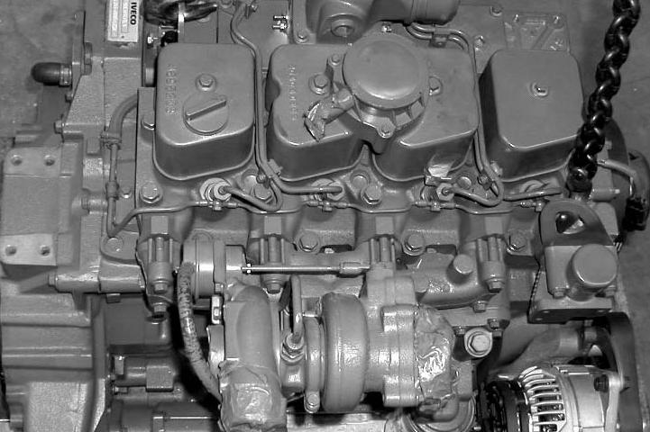
Disconnect the electrical wires and harnesses connected to the engine.
9 Engine oil pressure switch
10 Engine coolant solution temperature sender
11 Engine stop solenoid valve
12 Alternator (see section 4003 for wire identification)
13 Starter motor (see section 4004 for wire identification)
14 Earthing braid
15 Air filter restriction pressure switch
PDG0416
1 4 2 3 5 6
WX150 model
PDG0415
1 2 3 4 5 6 7
WX170-200 model
STEP
STEP 14
NOTE:
STEP
2002-5 Cre 9-54130GB Issued 03-03
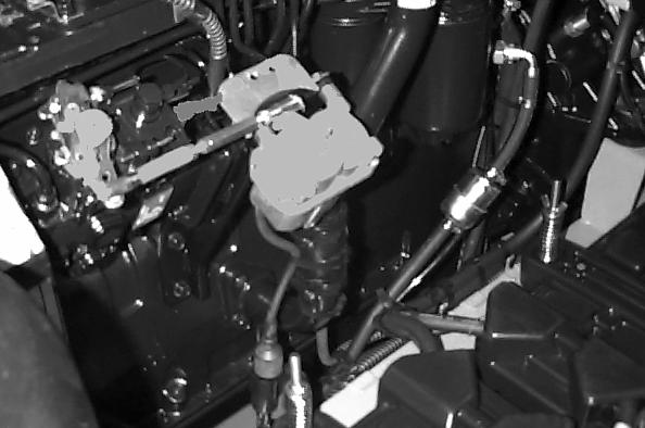
STEP 12
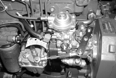
Disconnect the connector (1) from the servo-motor (2) and the connector (3) from the injection pump (4).
13
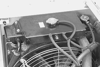
Remove the expansion reservoir cap.
Do not remove the cap when the engine is hot, since the system would still be under pressure and you could be scalded.
1 2 3 4
CD96A009
PG02824A
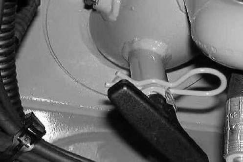
Turn the heater lever to the left.
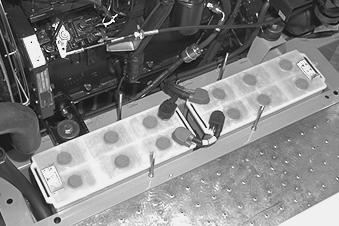
15
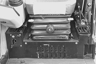
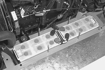
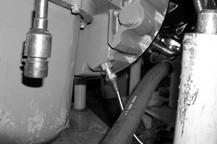
Remove the lower tray under the operator’s compartment. Position a receptacle of about 30 litres capacity, then disconnect the hose (1) from the heater unit and allow the coolant solution to drain out.
PG01706
1
PE07509
STEP 16
STEP 17
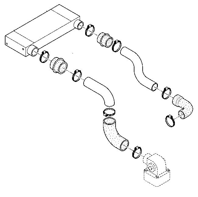
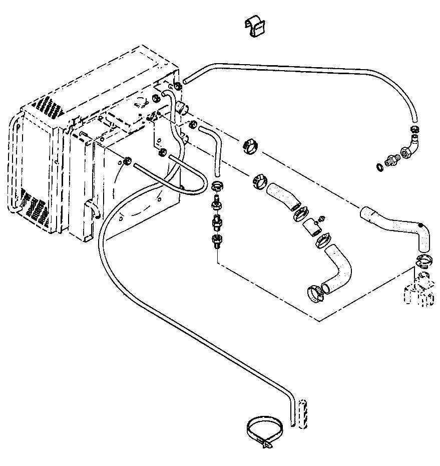
Disconnect, label, then remove the engine cooling system hoses in numerical order.
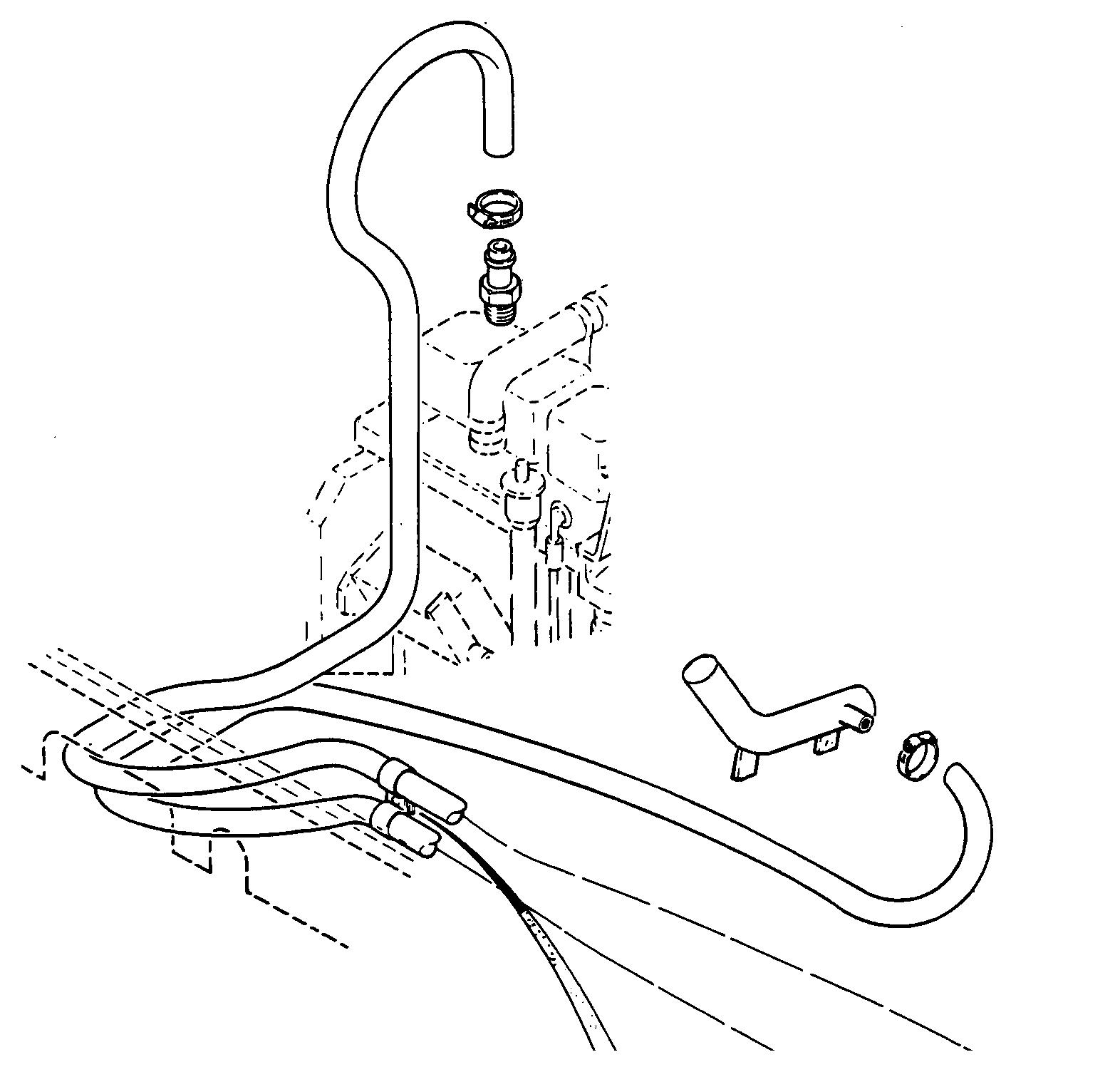
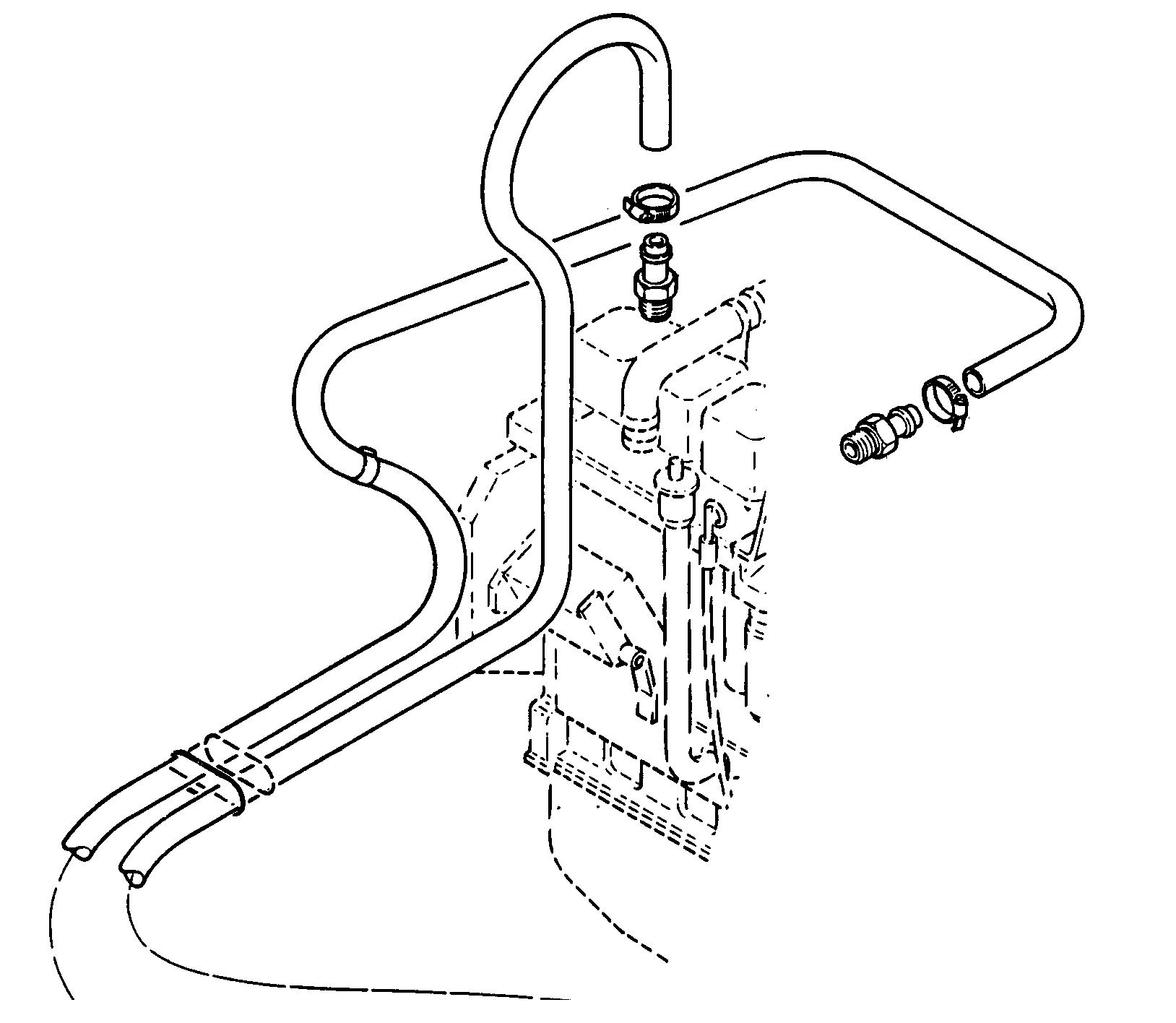
NOTE: When installing, make sure that the system hoses are clean.
2002-6 Cre 9-54130GB Issued 03-03
1 Overflow hose
2 Engine gas relief hose
3 Radiator gas relief hose
4 Engine/radiator return hose
5 Pump/radiator inlet hose
6 Coolant solution supply hose
PDG0407
7 Expansion reservoir
1 2 3 7 6 4 5 PDG0410
7 2 1 3 4 5 6 5
WX150 model
WX170-200 model
At the engine, disconnect the hoses (1) and (2) from the heater system.
PDG0412
1 2
WX150 model
PDG0411
2 1
WX170-200 model
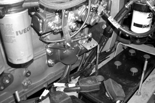
STEP 18
STEP 20
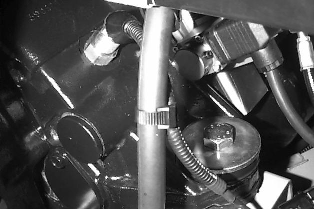
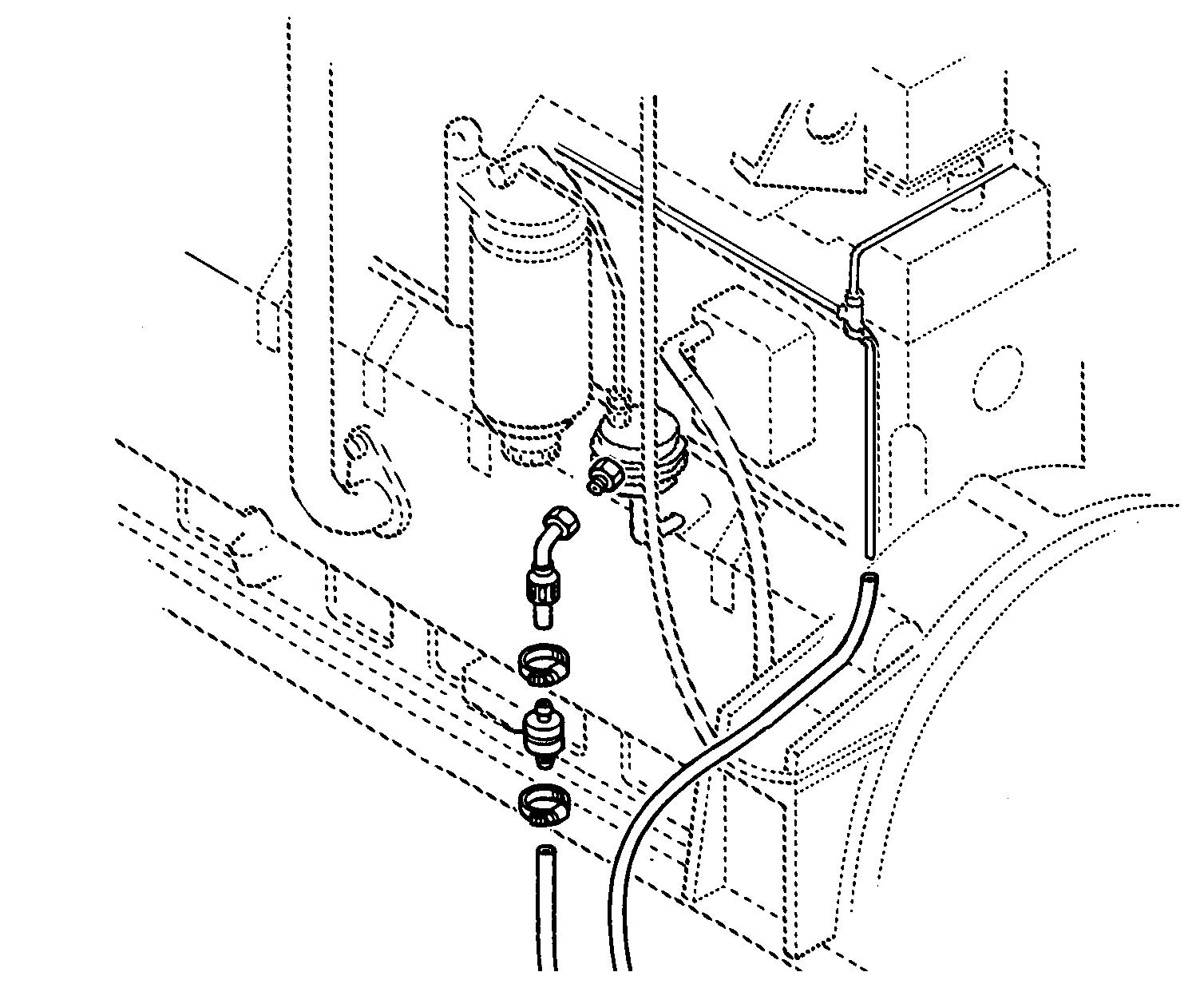
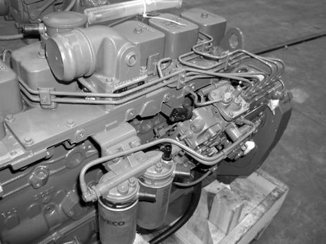
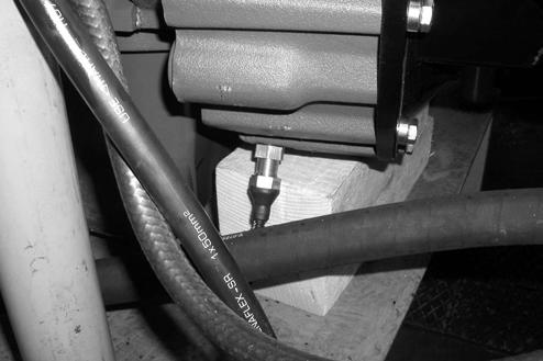
Disconnect the fuel supply pipe (1) and plug it. Disconnect the fuel return pipe (2) and plug it.
NOTE: When installing, change the filter (3).
STEP 19 WX150 model
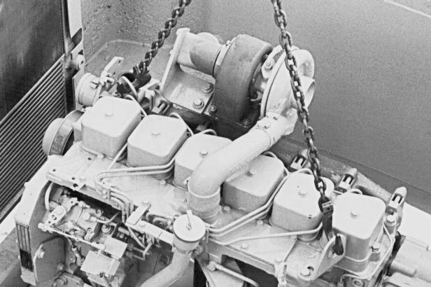
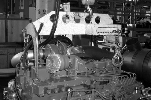
Install suitable lifting equipment on the engine lifting eyes.
Engine weight: WX150 model .............................................350 kg WX170-200 model ......................................443 kg
STEP 21
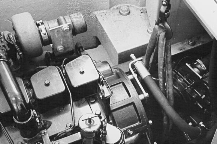
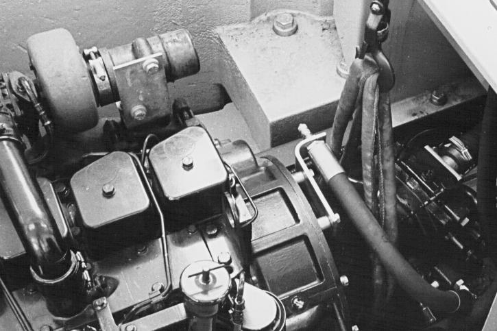
Remove and plug the hydraulic oil return hose to gain access to the sleeve retainers.
NOTE: Refer to the "Tools required" section, page 2, for plugging the hydraulic oil return hose.
Using a suitable sling, support the hydraulic pump to hold it in position when removing the engine.
STEP 22
Remove the hydraulic pump retaining hardware.
NOTE: When installing, tighten the hydraulic pump retaining screws to a torque of 44 Nm.
2002-7 Cre 9-54130GB Issued 03-03
2 3 1
PDG0409
PG02824B
B20308
C24000
C24000A
NOTE: (WX150), when installing, install the pressure control hose and its bracket.
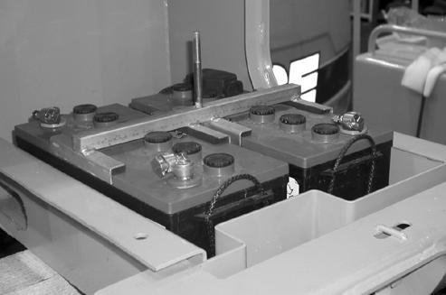
STEP 23
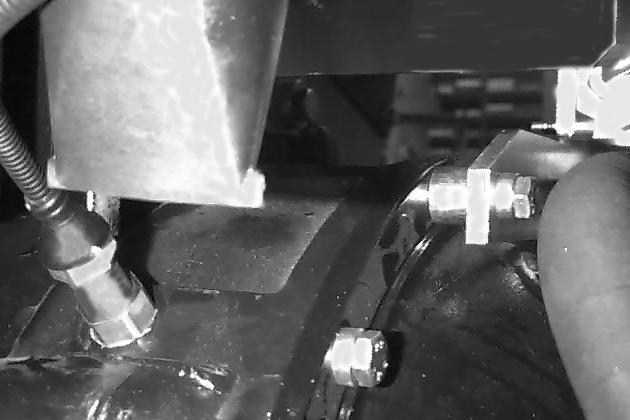
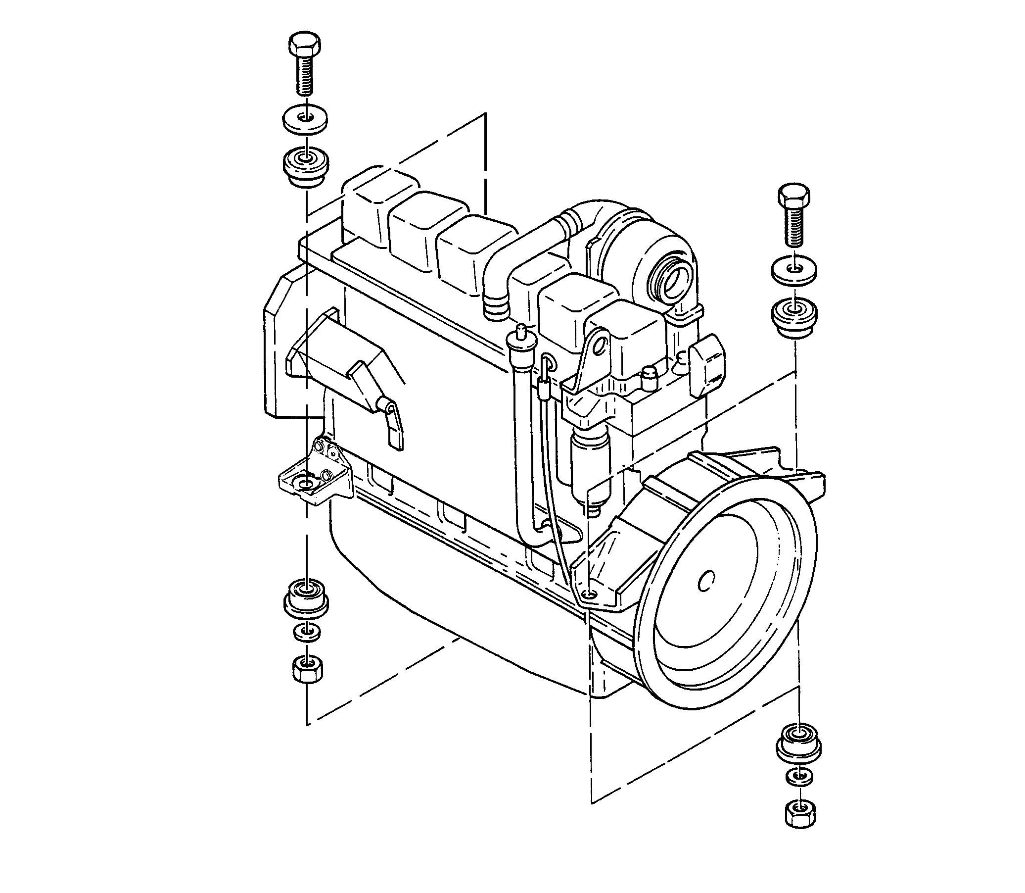
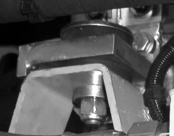
Remove the nuts (1), the washers (2) then remove the screws (3) and the thrust washers (4).
NOTE: When installing, make a visual check of the condition of the rubber spacers (5), replace them if necessary, tighten the engine bracket retaining screws to a torque of 217 to 271 Nm.
STEP 24
Carefully raise the engine and move it towards the radiator until it is clear of the pump coupling. When there is nothing to prevent the engine being removed, lift the engine and install it on a suitable repair bench.
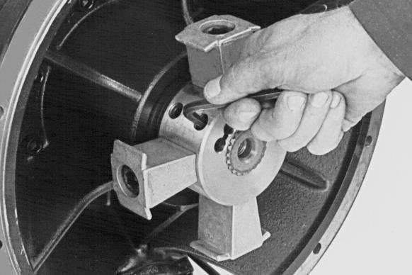
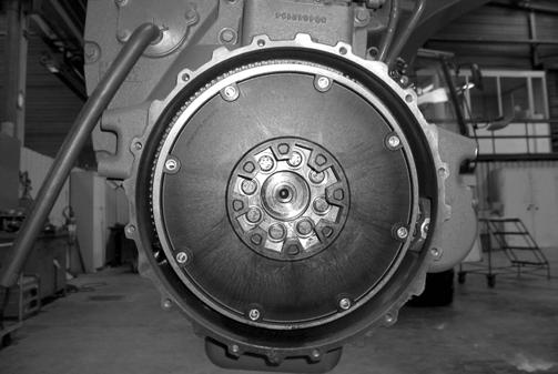
STEP 25
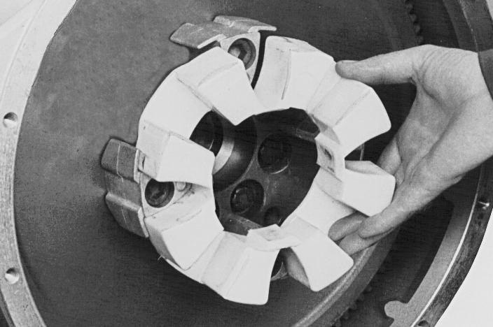
Remove the flexible coupling (1), check it visually for wear and condition and replace it if necessary.
STEP 26
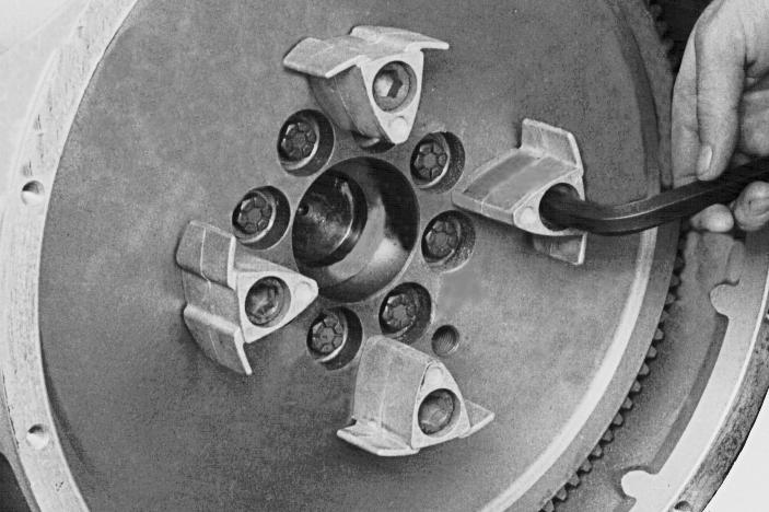
Remove the screws (1) then remove the centring studs (2). Check the centring studs for wear and condition and replace them if necessary.
NOTE:
INCORRECTCORRECT
When installing, apply Loctite 638 to the screws, position the centring studs correctly, then tighten the screws to a torque of 220 Nm.
2002-8 Cre 9-54130GB Issued 03-03
PDG0413 WX150 model 1 2 3 4 5 1 2 3 4 5 5 5 PDG0414 WX170-200 model 1 2 3 5 5 4 1 2 5 5 4 3
B20402 1 B20404 2 1 PDG0419
NOTE: If wear on the flexible coupling and centring studs necessitates their replacement, change the splined sleeve at the same time.
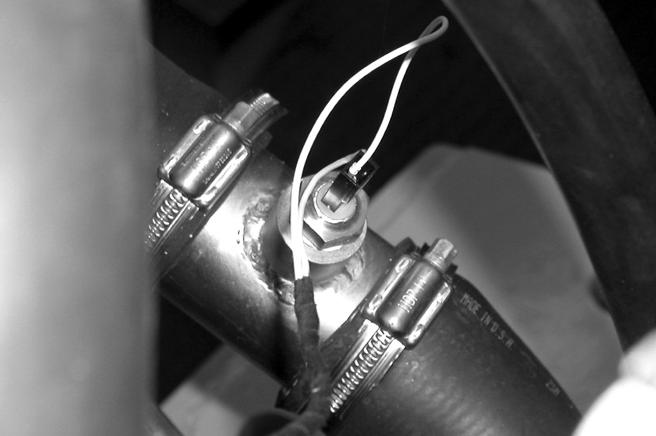
Checking electrical connections on temperature sensors
Remove the splined sleeve (1) from the hydraulic pump and change it if necessary.
NOTE: When installing the splined sleeve (1) assemble the splined sleeve on the pump shaft. The splined sleeve must butt up against the shoulder on the pump shaft. Tighten the retaining screws (2) to a torque of 100 Nm.
NOTE: When installing the engine, proceed in the reverse order from removal.
Before using the machine, perform all the following operations:
-Fill the cooling system (see operator’s manual).
-Turn the battery master switch to the "ON" position.
-Bleed and prime the fuel system (see operator’s manual).
-Check that the engine oil pressure warning lamp goes out when the engine is running.
-Adjust the engine speed detector if it has been removed, see section 4002.
-Calibrate the servo-motor if it has been removed, see section 4002.
-Bleed air from the cooling system (see operator’s manual).
-Check the hydraulic system, fuel system and cooling system for leaks.
-Shut down the engine and check all the levels. Top up if necessary.
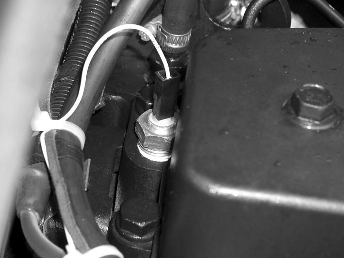
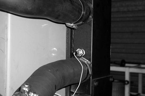
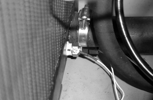
Disconnect the water temperature sensor on the engine cylinder head (2).
- Defect D005 shown on the control panel "Connection correct".
- Defect D007 shown "Error in connections between the engine water temperature detectors (2) and the cooling system detector (1)". Reverse the temperature sensor connection (1) and (2), the defect should disappear on the control screen.
2002-9 Cre 9-54130GB Issued 03-03
1
C18226
2
1
CD02H010
2
CD02H0011
2002-10 Cre 9-54130GB Issued 03-03
ENGINE REMOVAL AND INSTALLATION
WX150 : CGG0228401...
WX170 : CGG0232601...
WX200 : CGG0231801...
WX200M : CGG0233301...
CNH Copyright 2003 CNH France S.A. Printed in France. March 2003 Cre 9-88230GB 2002
Section 2002
TABLE OF CONTENTS
This symbol is used in this manual to indicate important safety messages. When ever you see this symbol, carefully read the message that follows, as there is a risk of serious injury.
SPECIAL TORQUES
- 1 torque wrench (10 to 15 Nm)
- 1 torque wrench (40 to 200 Nm)
- 1 torque wrench (70 to 360 Nm)
- 1 sling (400 to 600 kg)
- 2 slings (150 to 200 kg)
- 1 receptacle (30 litres)
TOOLS REQUIRED
- 1plugging spigot length 100 mm diameter 27 mm
- 1 Loctite 638
2002-2 Cre 9-88230GB Issued 03-03
SPECIFICATIONS ...................................................................................................................................................2 SPECIAL TORQUES................................................................................................................................................2 TOOLS REQUIRED ................................................................................................................................................2 Removal and installation ...................................................................................................... ...............................3 CHECKING ELECTRICAL CONNECTIONS TO THE RADIATOR TEMPERATURE SENSORS........................9
Weights: Engine, (without
Model WX150...............................................................................................................................................350kg Modèl WX170-200.......................................................................................................................................443kg High pressure hydraulic pump................................................................................................... Model WX150...............................................................................................................................................100kg Modèl WX170-200.......................................................................................................................................130kg Upper hood Model WX150.................................................................................................................................................26kg Modèl WX170-200.........................................................................................................................................43kg Capacity complete cooling system Model WX150...........................................................................................................................................14 Litres Modèl WX170-200...................................................................................................................................20 Litres Lubricants and coolant.............................................................................................................(see Section 1002)
SPECIFICATIONS
hydraulic pump)
Engine/hydraulic pump retaining screws.........................................................................................................44 Nm Splined sleeve retaining screws................................................................................................ ....................120 Nm Shock absorber centering lug retaining screws.............................................................................................220 Nm Engine support retaining screws........................................................................................................217 to 271 Nm
Before performing any service work on a machine, the following steps must be carried out in the order shown:
- Park the machine on hard, flat ground.
- Lower the attachment to the ground.
- Stop the engine and let it cool down.
- Turn the battery master switch to the “OFF” position and remove the key.
When the machine is running, the engine components and the hydraulic pump reach a high temperature. To avoid being burnt by hot metal or scalded by high temperature water or oil, let the machine cool down before beginning any operation.
Removal and installation
STEP 3
Drain the cooling circuit. See the Operator’s Manual. Remove the upper hood using a suitable lifting device.
NOTE : When installing, make sure that the exhaust outlet is pointing towards the rear.
STEP 4
Remove the upper hood using a suitable lifting device.
STEP 5
Remove the side panel on the walkway side.
STEP 6
Remove the exhaust silencer and its bracket.
STEP 7
Remove the hose connecting the air filter to the turbo charger, disconnect the air filter restriction pressostat and remove the air filter.
Disconnect the negative cable (1) first and then the other cables.
STEP 2
Remove the access panels located under the engine.
2002-3 Cre 9-88230GB Issued 03-03
STEP 1
WX150 model
WX170 and WX200 models
PG03613
1
CD02K027
STEP 8
2002-4 Cre 9-88230GB Issued 03-03
Disconnect the connector (1) from the speed detector (2).
STEP 9
CD96A008
Disconnect the electrical supply (1) from the proportional pressure reduction valve DRE4 (2)
1
2 2 1
CD02J006
CS03A536
STEP 10 WX150 model
WX170 and WX200 models
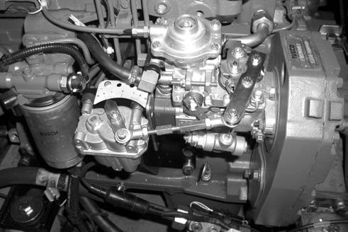
Disconnect the connector (1) and (2) from the injection pump
1 2
CD02K015
CD02K014
1
STEP 11
Disconnect the wires and electrical harnesses connected to the engine.
Engine oil pressure pressostat.
Engine coolant solution temperature sender.
Engine cut-out solenoid valve.
Alternator
Starter motor (see Section 4004), for wiring identification.

Earthing strap.
Air filter restriction pressostat.
Disconnect and place identification labels on the air circuit hoses.

NOTE : When installing, make sure the pipes and hoses are clean.
2002-5 Cre 9-88230GB Issued 03-03
WX150 model
PDG0416
PDG0415
WX170 and WX200 models
STEP 12
WX150 model
WX170 and WX200 models
CD02K016CS03A544
CS03A545
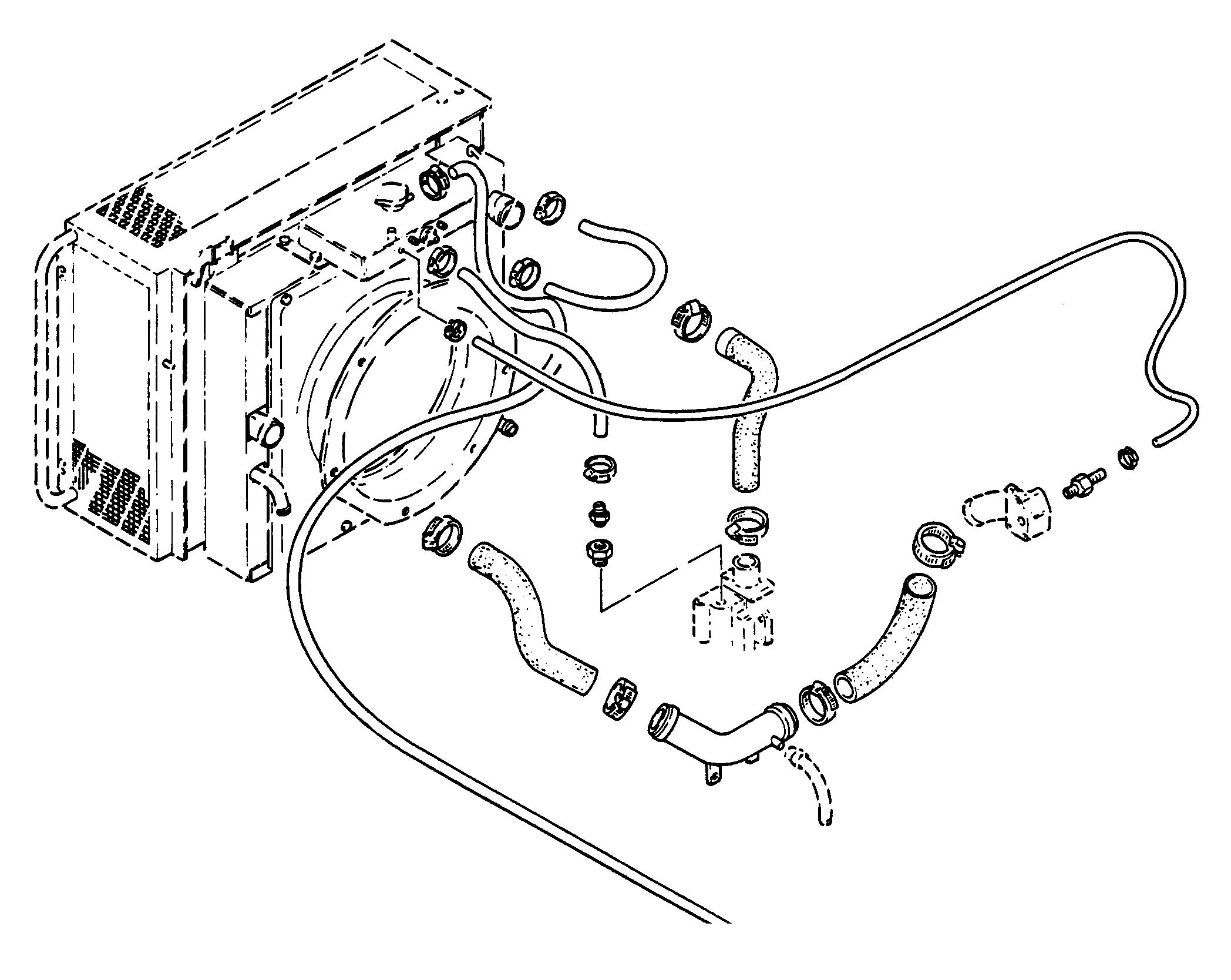
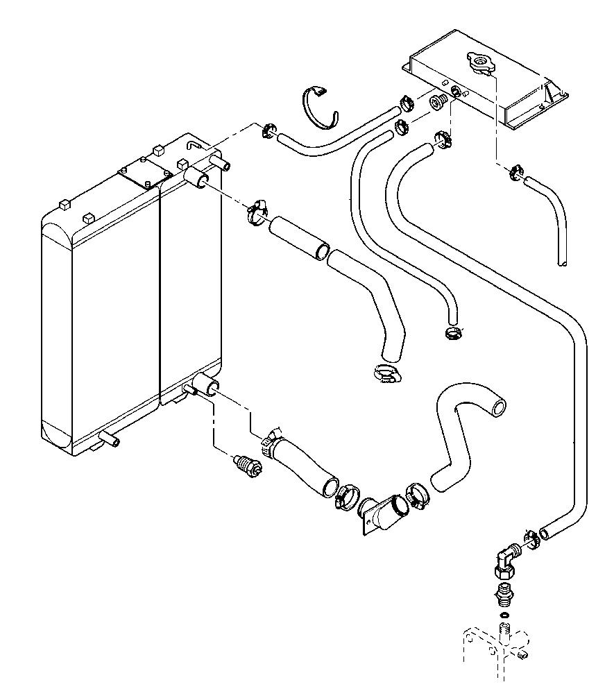
Disconnect, label and remove the cooling system hoses from the engine in numerical order.
NOTE : When installing, make sure that the system hoses are clean.
Overflow hose
Engine gas evacuation hose
Radiator gas evacuation hose
Engine/radiator return hose
Pump/radiator inlet hose
Coolant solution supply hose
Expansion reservoir
Disconnect, label and remove the cooling system hoses from the engine in numerical order.
NOTE : When installing, make sure that the system hoses are clean.
Engine gas evacuation hose
Radiator gas evacuation hose
Engine/radiator return hose
Pump/radiator inlet hose
Coolant solution supply hose
Expansion reservoir
STEP 13
Disconnect the fuel supply pipe (1) and plug it. Disconnect the fuel return pipe (2) and plug it.
NOTE : When installing, change the filter (3).
STEP 14
Remove and plug the hydraulic fluid return hose to gain access to the shroud retainers.
NOTE : Refer to “Tools required” on page 2 for plugging the hydraulic fluid return hose.
2002-6 Cre 9-88230GB Issued 03-03
WX150 model
CS03A547
CS03A546
WX170 and WX200 models
3 1 2
CD02K017
Weight of engine: WX150 model ..............................................410 kg WX170 and WX200 model..............................527 kg
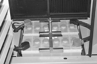
STEP 16
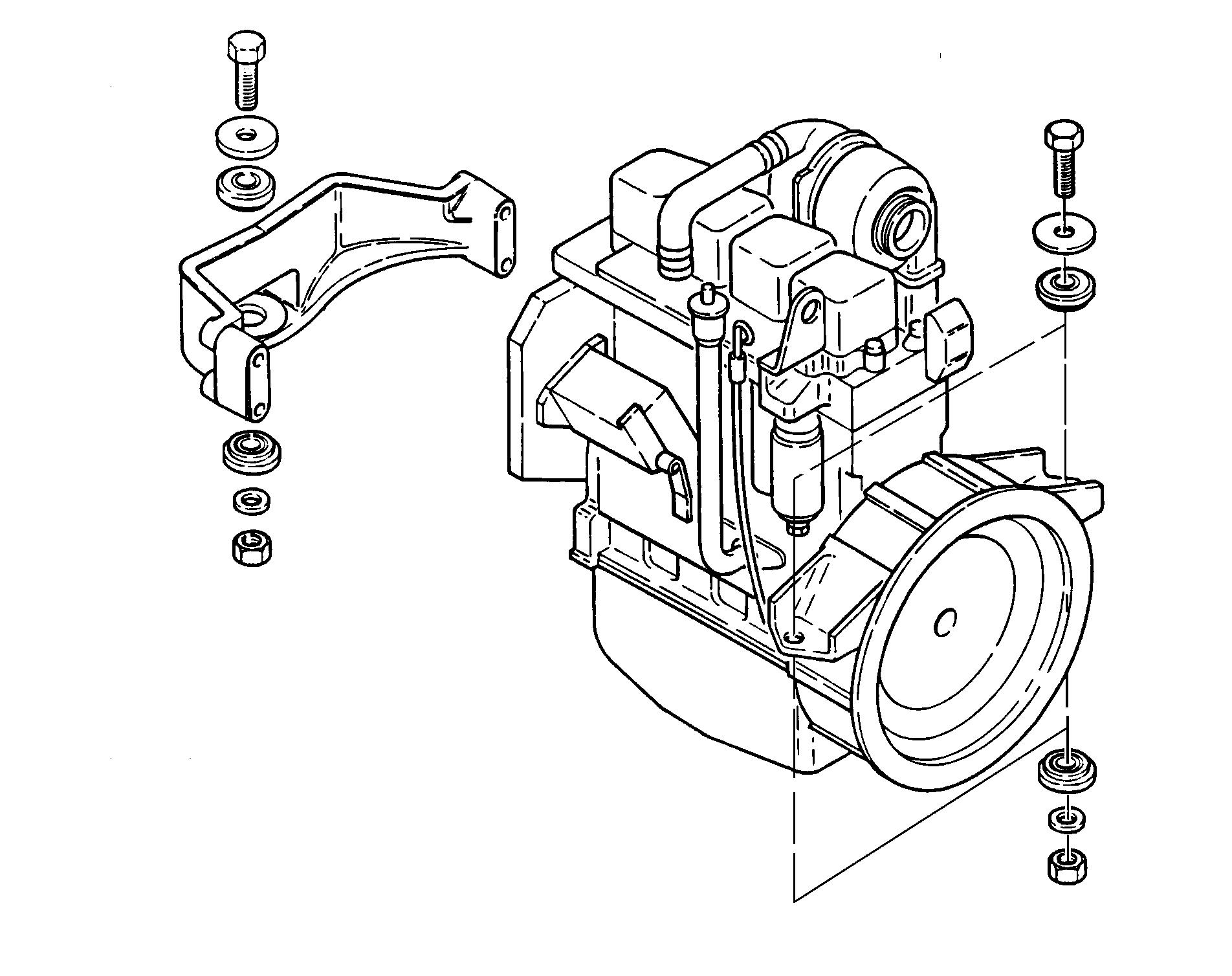
Remove the nuts (1), the washers (2) and remove the screws (3) and the thrust washers (4).
NOTE : When installing, make a visual check of the condition of the rubber spacers (5). Replace them with new spacers if necessary. Tighten the engine bearer retaining screws to a torque of 217 to 271 Nm.
Remove the hydraulic pump fastening hardware. When installing, tighten the hydraulic pump retaining screws to a torque of 44 Nm.
2002-7 Cre 9-88230GB Issued 03-03
STEP 15
WX150 model
Attach a suitable lifting device to the engine lifting eyes.
WX170 and WX200 model
Using a suitable sling, support the hydraulic pump so as to keep it in place during the removal of the engine.
CD02K018
CS03A537
C24000
STEP 17
STEP 18
4 3 5 4
3 4 5 5 2 1 3
CD02K019
CS03A538
STEP 19
Carefully lift the engine. Move it towards the radiator until it is disengaged from the pump coupling. When there is nothing to prevent the removal of the engine, install it on a suitable repair bench.
STEP 20
STEP 21
Remove the splined sleeve (1) from the hydraulic pump. Replace it if necessary.
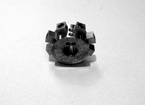
NOTE : When installing the splined sleeve (1), install the splined sleeve on the pump shaft. The splined sleeve should be pushed fully home against the pump shaft shoulder. Tighten the retaining screws (2) to a torque of 120 Nm.
NOTE: When installing the engine, proceed in the reverse order from removal.
Before using the machine, perform all the following operations:
-Fill the cooling system (see operator’s manual). Turn the battery master switch to the "ON" position.
-Bleed and prime the fuel system (see operator’s manual).
-Check that the engine oil pressure warning lamp goes out when the engine is running.
-Adjust the engine speed detector if it has been removed, see section 4002.
-Calibrate the servo-motor if it has been removed, see section 4002.
Bleed air from the cooling system (see operator’s manual).
-Check the hydraulic system, fuel system and cooling system for leaks. Stop the engine and check all levels. Top up if necessary.
2002-8 Cre 9-88230GB Issued 03-03
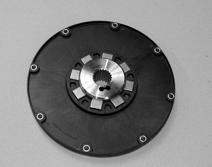
Remove the 8 screws (1) from the coupling, check that is in good condition and replace it if necessary.
When installing, apply Loctite 638 on the screws, and tighten the screws to a torque of 46 Nm.
1
CD02K020
CD02K026
2 1
CD02K021
- Code D005 is displayed on the control panel "Connections corect".
- Code D007 is displayed
"connection error between temperature detectors (2) and cooling circuit detector (1)".
Invert the wiring between temperature senders (2) and temperature sender (1). The message should disappear. I
2002-9 Cre 9-88230GB Issued 03-03
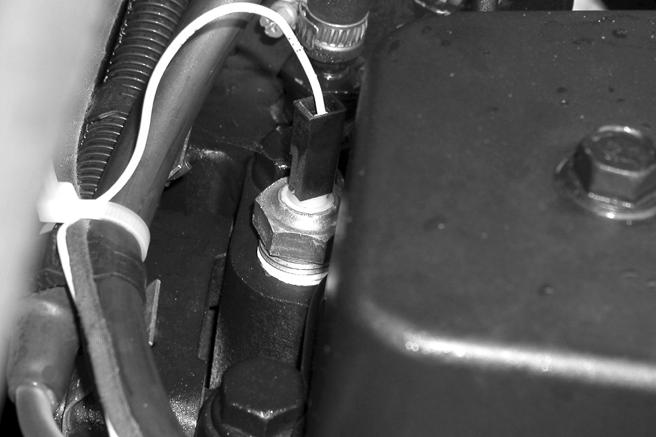
Checking electrical connections to the radiator temperature sensors.
WX150 model
WX170 and WX200 model
Remove the temperature sender from the engine cylinder head (2).
1
CD02K024
1
CD02K023
2
CD02H0011
2002-10 Cre 9-88230GB Issued 03-03
CNH Copyright 2002 CNH France S.A. Printed in France June 2002 Cre 9-53720GB 2003 RADIATOR AND OIL-COOLER Section 2003
WARNING: This symbol is used in this manual to indicate important safety messages. When you see the symbol, carefully read the message which follows. Your safety depends on it.
2003-2 Cre 9-53720GB Issued 06-02 TABLE OF CONTENTS SPECIFICATIONS .................................................................................................................................................. 3 TOOLS REQUIRED ............................................................................................................................................... 3 RADIATOR AND OIL-COOLER ............................................................................................................................. 4 Removal and installation ..................................................................................................................................... 4 REPLACING THE RADIATOR OR THE OIL-COOLER ......................................................................................... 7 WX170 and WX200 model .................................................................................................................................. 7 Disassembly and assembly ................................................................................................................................. 7
!
See Section 1002.
SPECIFICATIONS
IMPORTANT: When an ethylene-glycol based coolant is used, a minimum of 50% ethylene-glycol should always be present in the cooling circuit. Do not put more than 50% of ethylene-glycol in the cooling circuit, unless the ambient temperature is less than -36°C. A percentage greater than 50% of ethylene-glycol reduces temperature transfer and then the surface temperature of the engine rises above normal.
TOOLS REQUIRED
1 Torque wrench (10 to 50 Nm)
1 Sling (50 to 100 kg)
1 Container (30 litres)
2 Plugging pins 100 mm long and 27 mm in diameter
2003-3 Cre 9-53720GB Issued 02-06
RADIATOR AND OIL-COOLER
Before performing any service work on the machine, the following steps must be carried out in the order shown:
- Park the machine on flat, hard ground.
-Lower the attachment to the ground.
-Stop the engine.
-Turn the battery master switch to the "OFF" position and remove the key.
-Simultaneously operate the emergency foot pump and the control lever so as to release the pressure in the hydraulic system.
-Unscrew the pressure release plug on the hydraulic reservoir by two or three turns, then retighten the plug.
WARNING: When the machine is running, the engine and hydraulic pump components attain a high temperature. To avoid risk of burns from hot metal or boiling oil or water, allow the machine to cool down completely before carrying out any work.
Removal and installation
STEP 1
Remove the lower drawer under the operator’s compartment and the panels under the upperstructure.
STEP 2
Remove the expansion tank plug.
IMPORTANT: Do not remove the plug when the engine is hot, as the circuit is under pressure and you risk getting scalded.
STEP 3
Move the heating lever to the opening position.
STEP 4
Disconnect the heater return hose and let the cooling fluid flow into an appropriate receptacle. Reconnect the hose after the circuit has completely drained.
STEP 5
Close the valve on the hydraulic reservoir.
IMPORTANT: After an operation that requires closing the valve, never start the engine without ensuring that the valve has been reopened.
2003-4 Cre 9-53720GB Issued 02-06
CD99H004
CD99H009
!
STEP 6
WX150 model
STEP 8
Remove the engine upper hood.
Remove the upper hood traverse.
Remove the RH side panel.
Remove the inspection panel.
Remove and plug the radiator degassing hose.
Remove the expansion vessel.
Remove the upper panel.
Remove and plug the hydraulic fluid upper hose. To avoid losing fluid, disconnect the oil cooler return hose from the hydraulic reservoir and drain the oil from it into a clean receptacle. Reconnect the reservoir return hose and remove and plug the oil cooler hose.
NOTE: Refer to the section "Tooling required" on page 3 for plugging the hoses.
STEP 7
Remove and plug the engine/radiator return hose. Remove and plug the water pump/radiator inlet hose.
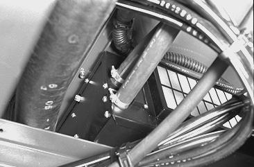
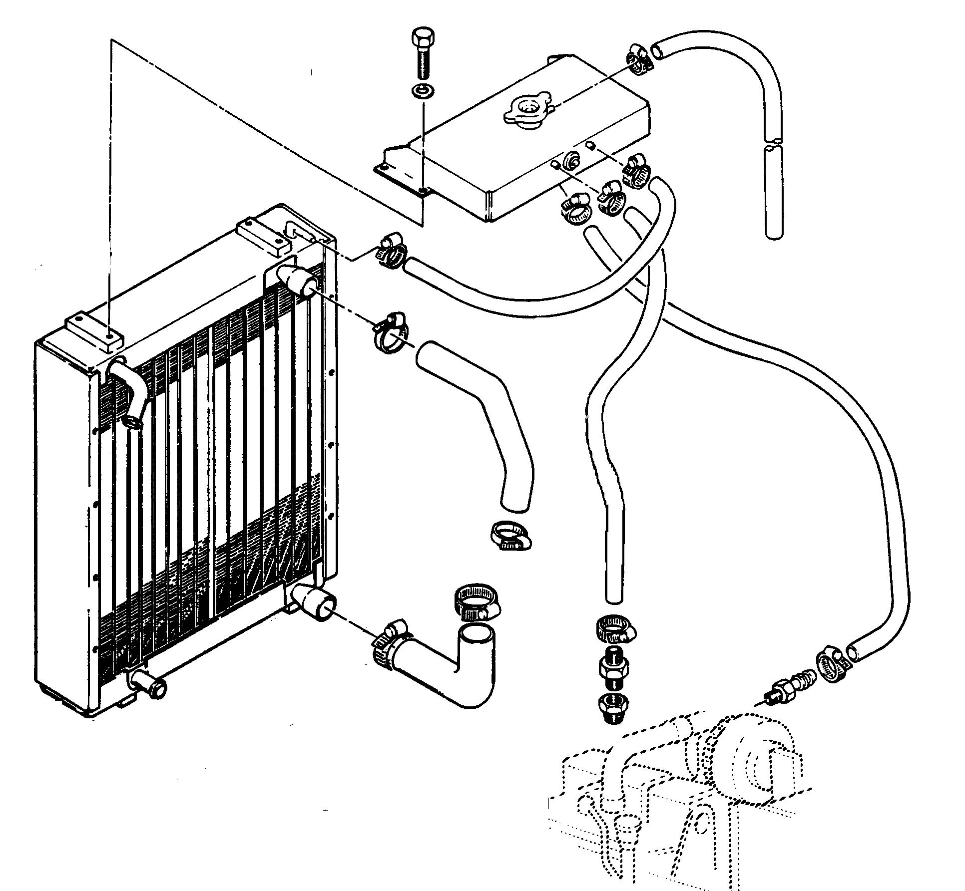
Remove the lower retainers (1) and (6) and the upper retainers (5) from the radiator (3). Remove the lower (4) and upper (5) flexible mountings.
Remove the lower retainers (1) and then the upper retainers (2) from the radiator (3). Remove the lower (4) and upper (5) flexible mountings.
NOTE: When installing, check visually for wear and the general condition of the flexible mountings (4) and (5) and change them if necessary.
2003-5 Cre 9-53720GB Issued 02-06
CS02H502
WX150 model
PDG0422BIS
WX170 - WX200 model
PDG0423
2 5 4 1 6 3 4 3 5 2 1
PDG0431
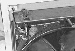
Using a suitable sling, encircle the radiator, then remove it.
NOTE: When installing, proceed in the reverse order to that of removal.
Before using the machine, carry out all the following operations:
-Check the oil level in the hydraulic reservoir. Top up if necessary.
-Turn the battery master switch to the "ON" position.
-Fill the cooling system (see Operator’s Manual).
-Bleed the cooling system (see Operator’s Manual).
-Check the hydraulic cooling circuit for leaks.
2003-6 Cre 9-53720GB Issued 02-06
STEP 9
REPLACING THE RADIATOR OR THE OIL-COOLER
WX170 and WX200 model Disassembly and assembly
NOTE: The parts are numbered in the order of disassembly, when assembling follow the reverse order.
2003-7 Cre 9-53720GB Issued 02-06
3 5 2 6 1 4
CS02H503 1BRACKET 2NUT 3COOLING FLUID RADIATOR 4SCREW 5FOAM SEAL 6HYDRAULIC OIL COOLER
2003-8 Cre 9-53720GB Issued 02-06
CNH Copyright 1999 CNH France S.A. Printed in France November 1999 Cre 7-58691GB 4003
Section 4003
STARTER MOTOR
SPECIAL TORQUES
WORKSHOP TOOLS
4003-2 Cre 7-58691GB Issued 11-99 TABLE
CONTENTS SPECIFICATIONS....................................................................................................................................................2 SPECIAL TORQUES................................................................................................................................................2 SHOP EQUIPMENT TOOLS....................................................................................................................................2 STARTER MOTOR Removal and Installation......................................................................................................................................3 No-Load test procedure.......................................................................................................................................4 Understanding No-Load test results.....................................................................................................................5 Disassembly and Assembly.................................................................................................................................6 Inspection.............................................................................................................................................................7 SPECIFICATIONS Manufacturer....................................................................................................................................................Bosch Weight...........................................................................................................................................................................25.5 kg No-Load test at 27°C Volts................................................................................................................................................................24 V Current draw............................................................................................................................85 amps maximum Brush length.................................................................................................................................................8.5 mm minimum Commutator diameter................................................................................................................................42.5 mm minimum Armature shaft end play..................................................................................................................................0.05 to 0.5 mm Armature shaft run-out..............................................................................................................................0.03 mm maximum Lubricant for thrust bearing and splines on armature shaft......................................................................GE silicone grease G321 Versilube
OF
Drive housing screws..............................................................................................................................4.5 to 6 Nm Starter motor mounting bolts.........................................................................................................................................43 Nm
1 Sun electric VAT-33 2 Hand-held tachometer CAS 10756 3 Multimeter CAS 1559 4 Dial indicator CAS 10066-1A 5 Magnetic base for dial indicator OEM 1030 6 Torque wrench OEM 6479
