CX210 - CX230 - CX240 Crawler Excavators
Copyright 2005 CNH France S.A. Printed in France CNH Cre 9-93540GBMay 2005
Table of Contents DIVISION/SECTIONSECTION N ° REFERENCE N ° 1GENERAL INFORMATION Safety, general information and standard torque data.....................................10017-27690GB General specifications and special torque setting............................................10027-29361GB 2ENGINE Removal and installation of the engine............................................................20007-28230GB Radiator and oil-cooler.....................................................................................20017-28050GB Engine specifications.............................................................................................* Disassembly and assembly of the engine..............................................................* 3FUEL SYSTEM Fuel tank..........................................................................................................30017-27970GB Fuel engine system................................................................................................* 4ELECTRICAL SYSTEM Electrical system, electrical and electronic troubleshooting.............................40017-27724GB Inspection and maintenance of batteries and connecting a booster battery....40027-27921GB Main and engine electronic control boxes........................................................40037-27933GB 5UNDERCARRIAGE Removal and installation of tracks...................................................................50017-27750GB Rollers..............................................................................................................50037-27772GB Sprocket...........................................................................................................50047-27781GB Idler wheel and tension shock absorber..........................................................50057-27803GB 6DRIVE TRAIN Drive motor and final drive transmission removal and installation...................60017-27841GB Drive motor and final drive transmission disassembly and assembly..............60027-28090GB Swing reduction gear, removal and installation................................................60037-27820GB Swing reduction gear, disassembly and assembly (CX210 - CX230)..............60047-28371GB Swing reduction gear, disassembly and assembly (CX240)............................60047-28391GB
HYDRAULICS
HYDRAULICS Depressurising and decontaminating the hydraulic system, use of the vacuum pump and bleeding the components..............................................80007-27952GB Specifications, troubleshooting, checks and hydraulic pressure settings........80017-27704GB Hydraulic reservoir removal and installation....................................................80027-27990GB Main and pilot pumps, removal and installation...............................................80037-27860GB Main hydraulic control valve, removal and installation.....................................80047-27890GB Attachment cylinders, removal and installation................................................80057-27791GB Hydraulic swivel, removal and installation.......................................................80067-27811GB Pilot blocs, removal and installation.................................................................80077-28130GB Swing motor, removal and installation (CX210 - CX230).................................80087-28071GB Swing motor, removal and installation (CX240)...............................................80087-28071GB Main hydraulic pump, disassembly and assembly...........................................80107-35490GB Main hydraulic control valve, disassembly and assembly................................80119-36270GB Attachment cylinders, disassembly and assembly...........................................80127-27902GB Hand control levers, disassembly and assembly.............................................80137-28110GB Foot control levers, disassembly and assembly..............................................80147-28210GB Six-solenoid valves, disassembly and assembly.............................................80157-27911GB Caution valve, disassembly and assembly......................................................80167-27942GB Safety valve.....................................................................................................80177-29631GB Hydraulic swivel, disassembly and assembly..................................................80187-28080GB Swing motor, disassembly and assembly (CX210 - CX230)............................80197-28011GB Swing motor, disassembly and assembly (CX240)..........................................80197-29760GB Hydraulic functions...........................................................................................80207-28490GB
7UNDERCARRIAGE
8UPPERSTRUCTURE
Thanks very much for your reading, Want to get more information, Please click here, Then get the complete manual
NOTE:
If there is no response to click on the link above, please download the PDF document first,andthen click on it.

* Consult the Engine Service Manual
Sections to be distributed at a later date
NOTE: CNH Company reserves the right to make changes in the specification and design of the machine without prior notice and without incurring any obligation to modify units previously sold.
The description of the models shown in this manual has been made in accordance with the technical specifications known as of the date of design of this document.
Cre 9-93540GB Issued 05-05 DIVISION/SECTIONSECTION N°REFERENCE N° 9UPPERSTRUCTURE Quick coupler...................................................................................................90009-93630GB Upperstructure, turntable and counterweight...................................................90027-27982GB Boom, dipper and bucket.................................................................................90037-27963GB Seat and seat belt............................................................................................90047-28120GB Cab and cab equipment...................................................................................90057-28022GB Air conditioning troubleshooting.......................................................................90069-88730GB Air conditioning unit disassembly and assembly..............................................90077-29910GB Air conditioning servicing.................................................................................9008 Air conditioning components............................................................................9009
format hydraulic and electrical schematics.........................................Pocket7-27623
Large
Case Copyright 2000 Case France Printed in France September 2000 Cre 7-27690GB 1001
TORQUE SPECIFICATIONS Section 1001
SAFETY, GENERAL INFORMATION AND
SAFETY.....................................................................................................................................................................4
STANDARD TORQUE DATA FOR CAP SCREWS AND NUTS...............................................................................6
WARNING : This symbol is used in this manual to indicate important safety messages. Whenever you see this symbol, carefully read the message that follows, as there is a risk of serious injury.
1001-2 Cre 7-27690GB Issued 09-00
TABLE OF CONTENTS GENERAL INFORMATION.......................................................................................................................................3
!
GENERAL INFORMATION
Cleanning
Clean all metal parts except bearings, in a suitable cleaning solvent or by steam cleaning. Do not use caustic soda for steam cleaning. After cleaning, dry and put oil on all parts. Clean oil passages with compressed air. Clean bearings in a suitable cleaning solvent, dry the bearings completely and put oil on the bearings.
Inspection
Check all parts when the parts are disassembled. Replace all parts that have wear or damage. Small scoring or grooves can be removed with a hone or crocus cloth. Complete a visual inspection for indications of wear, pitting and the replacement of parts necessary to prevent early failures.
Bearings
Check bearings for easy action. If bearings have a loose fit or rough action replace the bearing. Wash bearings with a suitable cleaning solvent and permit to air dry. DO NOT DRY BEARINGS WITH COMPRESSED AIR.
Needle bearings
Before you press needle bearings in a bore always remove any metal protrusions in the bore or edge of the bore. Before you press bearings into position put petroleum jelly on the inside and outside diameter of the bearings.
Gears
Check all gears for wear and damage. Replace gears that have wear or damage.
Oil seals, O-rings and gaskets
Always install new oil seals, O-rings and gaskets. Put petroleum jelly on seals and O-rings.
Shafts
Check all shafts that have wear or damage. Check the bearing and oil seal surfaces of the shafts for damage.
Service parts
Always install genuine Case service parts. When ordering refer to the Parts Catalog for the correct part number of the genuine Case replacement items. Failures due to the use of other than genuine Case replacement parts are not covered by warranty.
Lubrication
Only use the oils and lubricants specified in the Operator’s or Service Manuals. Failures due to the use of non-specified oils and lubricants are not covered by warranty.
1001-3 Cre 7-27690GB Issued 09-00
SAFETY
This symbol means ATTENTION! BECOME ALERT! YOUR SAFETY IS INVOLVED. The message that follows the symbol contains important information about safety. Carefully read the message. Make sure you fully understand the causes of possible injury or death.
To prevent injury always follow the Warning, Caution and Danger notes in this section and throughout the manual.
Put the warning tag shown below on the key for the keyswitch when servicing or repairing the machine. One warning tag is supplied with each machine. Additional tags Part Number 331-4614 are available from your service parts supplier
.
WARNING: Read the operator’s manual to familiarize yourself with the correct control functions.
WARNING: Operate the machine and equipment controls from the seat position only. Any other method could result in serious injury.
WARNING: This is a one man machine, no riders allowed.
WARNING: Before starting engine, study Operator’s Manual safety messages. Read all safety signs on machine. Clear the area of other persons. Learn and practice safe use of controls before operating. It is your responsibility to understand and follow manufacturers instructions on machine operation, service and to observe pertinent laws and regulations. Operator’ s and Service Manuals may be obtained from your Case dealer.
WARNING: If you wear clothing that is too loose or do not use the correct safety equipment for your job, you can be injured. Always wear clothing that will not catch on objects. Extra safety equipment that can be required includes hard hat, safety shoes, ear protection, eye or face protection, heavy gloves and reflector clothing.
WARNING: When working in the area of the fan belt with the engine running, avoid loose clothing if possible, and use extreme caution.
WARNING: When doing checks and tests on the equipment hydraulics, follow the procedures as they are written. DO NOT change the procedure.
WARNING: When putting the hydraulic cylinders on this machine through the necessary cycles to check operation or to remove air from a circuit, make sure all people are out of the way.
1001-4 Cre 7-27690GB Issued 09-00
!
!
!
!
!
!
!
!
!
WARNING: Use insulated gloves or mittens when working with hot parts.
WARNING: Lower all attachments to the ground or use stands to safely support the attachments before you do any maintenance or service.
WARNING: Pin sized and smaller streams of hydraulic oil under pressure can penetrate the skin and result in serious infection. If hydraulic oil under pressure does penetrate the skin, seek medical treatment immediately. Maintain all hoses and tubes in good condition. Make sure all connections are tight. Make a replacement of any tube or hose that is damaged or thought to be damaged. DO NOT use your hand to check for leaks, use a piece of cardboard or wood.
WARNING: When servicing or repairing the machine, keep the shop floor and operator’s compartment and steps free of oil, water, grease, tools, etc. Use an oil absorbing material and/or shop cloths as required. Use safe practices at all times.
WARNING: Some components of this machine are very heavy. Use suitable lifting equipment or additional help as instructed in this Service Manual.
WARNING: Engine exhaust fumes can cause death. If it is necessary to start the engine in a closed place, remove the exhaust fumes from the area with an exhaust pipe extension. Open the doors and get outside air into the area.
WARNING: When removing hardened pins such as a pivot pin, or a hardened shaft, use a soft head (brass or bronze) hammer or use a driver made from brass or bronze and a steel head hammer.
WARNING: When using a hammer to remove and install pivot pins or separate parts using compressed air or using a grinder, wear eye protection that completely encloses the eyes (approved goggles or other approved eye protectors).
WARNING: Use suitable floor (service) jacks or chain hoist to raise wheels or tracks off the floor. Always block machine in place with suitable safety stands.
WARNING: When the battery electrolyte is frozen, the battery can explode if (1), you try to charge the battery, or (2), you try to jump start and run the engine. To prevent the battery electrolyte from freezing, try to keep the battery at full charge. If you do not follow these instructions, you or others in the area can be injured.
1001-5 Cre 7-27690GB Issued 09-00
!
!
!
!
!
!
!
!
!
!
STANDARD TORQUE DATA FOR CAP SCREWS AND NUTS
Tightening of cap screws, nuts
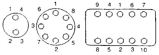
Tighten alternately so that tightening torque can be applied evenly. The numbers in the figure below indicate the order of tightening.
Cap screws which have had Loctite used (white residue remains after removal) should be cleaned with loght oil or suitable cleaning solvent and dried. Apply 2-3 drops of Loctite to the thread portion of the cap screw and then tighten.
1001-6 Cre 7-27690GB Issued 09-00
JS00481A
Torque table
Tighten cap screws and nuts according to the table below if there are no other special instructions.
1001-7 Cre 7-27690GB Issued 09-00
Cap Screw Name Size (Size)M6M8M10M12M14M16M18M20 Cap Screw Spanner [mm]1013171922242730 [in.]0.390.510.670.750.870.951.061.18 Tightening torque [Nm]6.915.732.358.898.0137.2196.0274.0 [lb-ft]5.111.623.943.472.3101.2144.6202.4 Socket Head Cap Screw Spanner [mm]5681012141417 [in.]0.200.240.320.390.470.550.550.67 Tightening torque [Nm]8.821.642.178.4117.6176.4245.0343.0 [lb-ft]6.515.931.157.886.8130.1180.8253.1
1001-8 Cre 7-27690GB Issued 09-00
CNH Copyright 2005 CNH France S.A. Printed in France May 2005 Cre 7-29361GB 1002
ANDSPECIALTORQUESETTINGS Section 1002
GENERAL SPECIFICATIONS
TABLE OF CONTENTS
WARNING: This symbol is used in this manual to indicate important safety messages. Whenever you see this symbol, carefully read the message that follows, as there is a risk of serious injury. !
1002-2 Cre 7-29361GB Issued 05-05
TYPE, SERIAL NUMBER AND YEAR OF MANUFACTURE OF THE MACHINE....................................................3 Machine.................................................................................................................................................................3 Engine...................................................................................................................................................................3 Component serial numbers...................................................................................................................................3 FLUIDS AND LUBRICANTS.....................................................................................................................................4 Hydraulic fluid....................................................................................................................................................... 4 Transmission component oil................................................................................................................................ 4 Grease................................................................................................................................................................. 4 Engine oil..............................................................................................................................................................5 Oil viscosity/Oil range............................................................................................................................................5 Fuel...................................................................................................................................................................... 6 Anti-freeze/Anti-corrosion..................................................................................................................................... 6 Environment......................................................................................................................................................... 6 Components made from plastic or resin.............................................................................................................. 6 SPECIFICATIONS.....................................................................................................................................................7 Engine...................................................................................................................................................................7 Capacities.............................................................................................................................................................7 Electrical system...................................................................................................................................................7 Hydraulic system...................................................................................................................................................8 Cylinder.................................................................................................................................................................8 Control valve.........................................................................................................................................................9 Swing....................................................................................................................................................................9 Travel....................................................................................................................................................................9 Undercarriage.......................................................................................................................................................9 Attachment............................................................................................................................................................9 Weight of components........................................................................................................................................10 DIMENSIONS AND LIMIT OF WEAR AND TEAR OF THE TRACKS SET............................................................11 Toothed wheel.....................................................................................................................................................11 Idler wheel...........................................................................................................................................................12 Upper roller.........................................................................................................................................................13 Lower roller.........................................................................................................................................................14 Track...................................................................................................................................................................15 DIMENSIONS AND LIMIT OF WEAR AND TEAR OF THEMOBILEJOINTSOFTHE ATTACHMENT................16 Boom foot/Undercarriage....................................................................................................................................16 Boom cylinder foot/Undercarriage.......................................................................................................................17 Boom cylinder head/Boom..................................................................................................................................17 Dipper cylinder foot/Boom...................................................................................................................................18 Boom/Dipper.......................................................................................................................................................18 Dipper cylinder head/Dipper................................................................................................................................18 Bucket cylinder foot/Dipper.................................................................................................................................19 Connecting rod/Dipper........................................................................................................................................19 Compensator/Bucket...........................................................................................................................................19 Connecting rod/Compensator/Bucket cylinder head...........................................................................................20 Dipper/Bucket......................................................................................................................................................20 SPECIAL TORQUE SETTINGS..............................................................................................................................21 MACHINE OVERALL DIMENSIONS.......................................................................................................................24
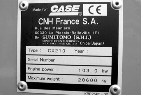
TYPE, SERIAL NUMBER AND YEAR OF MANUFACTURE OF THE MACHINE
When placing a parts order or making a request for information or assistance, always give you CASE Dealer the type and serial number of the machine concerned.
Enter the required information on the lines below: Type, serial number, year of manufacture of the machine and the serial numbers of hydraulic and mechanical components
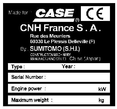
Machine
(1) Type.............................................................................
(2) Serial number..............................................................
(3) Year of manufacture....................................................
Engine
Make and type..................................................................................................................
Serial number..............................................................................................................................................................
Component serial numbers
Hydraulic pump.................................................................................................................
Swing reduction gear...........................................................................................................
Travel reduction gears.........................................................................................................
Travel control valve......................................................................................................................................................
Attachment control valve.......................................................................................................
Swing control valve............................................................................................................
Cre 7-29361GB Issued 05-05
1002-3
CT04D014
CT04A171
1 2 3
FLUIDS AND LUBRICANTS
Lubricants must have the correct properties for each application.
WARNING: The conditions of use for individual fluids and lubricants must be respected.
Hydraulic fluid
CASE hydraulic fluid is specially designed for high pressure applications and for the CASE hydraulic system. The type of fluid to be used depends on the ambient temperature.
Temperate climates
-20°C to +40°C
Fluid type ISO VG 46
CASE reference: POHYDR
Hot climates
0°C to +60°C
Fluid type ISO VG 100
CASE reference: POHYPC
Cold climates
-40°C to +20°C
Fluid type ISO VG 22
CASE reference: POHYPF
These various grades of fluid must be in conformity with the CASE specification.
Transmission component oil
Extreme pressure oil used for transmission components inside sealed housings.
Extreme pressure oil TYPE API GL5 GRADE 80W90 or ISO VG 150.
Grease
The type of grease to use depends on ambient temperature.
Temperate and hot climates
-20°C to +60°C
Extreme pressure grease EP NLGI grade 2 with molybdenum disulphide.
Cold climates
-40°C to +20°C
Extreme pressure grease EP NLGI grade 0.
1002-4 Cre 7-29361GB Issued 05-05
!
Engine oil
CASE engine oil No. 1 is recommended for your engine. This oil ensures correct lubrication of your engine in all working conditions.

If CASE No. 1 Multiperformance or Performance engine oil is not available, use oil corresponding to category API/CG/CF.
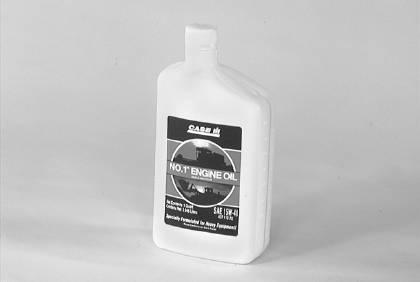
NOTE: Do not put any Performance Additive or other additive in the sump. Oil change intervals shown in this manual are based on tests carried out on CASE lubricants.
Oil viscosity/Oil range
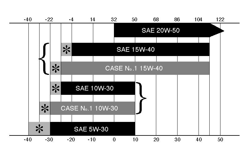
1002-5 Cre 7-29361GB Issued 05-05
RD97F136
RD97F100
TEMPERATURE
WINTER
CELSIUS TEMPERATURE (3) TROPICAL
ALL SEASONS (4) ARCTIC
SHOWS THAT AN ENGINE OIL HEATER OR ENGINE COOLANT SOLUTION HEATER MUST BE USED B A 3 1 2 4
CS98M561
(A) FAHRENHEIT
(2)
(B)
(1)
(*)
Fuel
Use fuel that is to ASTM (American Society for Testing and Materials) D975 standard.
Use Grade No. 2 fuel. The use of other types of fuel can result in a loss of power and may cause high fuel consumption.
In cold weather, the use of a mixture of fuels No. 1 and No. 2 is temporarily permitted. Consult your fuel supplier.
If the temperature falls below the fuel cloud point (point at which wax begins to form) the wax crystals will cause power loss or will prevent the engine from starting.
IMPORTANT: In cold weather, fill the fuel tank at the end of the day’s work, in order to prevent the formation of condensation.
Fuel storage
Long storage can lead to the accumulation of impurities and condensation in the fuel. Engine trouble can often be traced to the presence of water in the fuel. The storage tank must be placed outside and the temperature of the fuel should be kept as low as possible. Drain off water and impurities regularly.
Anti-freeze/Anti-corrosion
Use anti-freeze in all seasons to protect the cooling system from corrosion and all risk of freezing.
In environments with a temperature higher than -36°C, use a mixture of 50% ethylene-glycol based anti-freeze.
For areas where the temperature is below -36°C, it is advisable to use a blend of 40% water and 60% antifreeze.
Environment
Before carrying out any servicing operation on this machine and before disposing of used fluids or lubricants, always think of the environment. Never throw fluid or oil on the ground and never keep them in leaking receptacles.
Consult your local ecological recycling centre to obtain information on the appropriate means of disposing of these substances.
Components made from plastic or resin
When cleaning plastic parts, the console, the instrument panel, the gauges, etc., do not use petrol (gasoline), paraffin (kerosene), paint solvents, etc. Use only water, soap and a soft cloth.
The use of petrol (gasoline), paraffin (kerosene), paint solvents, etc, will cause discoloration, cracking or deformation of these components.
Cre 7-29361GB Issued 05-05
1002-6
Capacities
SPECIFICATIONS
sight glasses or the filler cap.
Electrical system
1002-7 Cre 7-29361GB Issued 05-05
Engine CX210/CX230CX240 Make..............................................................................................Isuzu...........................................................Isuzu Model...........................................................................................................................BB-6BG1T Type: Four stroke,
in-line
Number of cylinders.............................................................................................................6 Bore and stroke..........................................................................................................105x125 mm Displacement................................................................................................................6494 cm3 Operating conditions Idling.............................................................................................................................1000 rpm Max speed..................................................................................1950 rpm..................................................2150 rpm ECC 1289 power rating........................................................105 kW (143 hp).............................140,5 kW (190 hp) Max torque.........................................................................532 Nm at 1600 rpm.......................676 Nm at 1800 rpm
water-cooled, overhead valve, direct injection (electronically controlled),
engine with turbo-charger.
Engine oil capacity..........................................................................................................24 litres Engine cooling system....................................................................................................27 litres Capacity of the radiator only........................................................12 litres..................................................12.2 litres Fuel tank.....................................................................................265 litres..................................................340 litres Hydraulic fluid reservoir capacity...................................................................................120 litres Total hydraulic system capacity..................................................206 litres..................................................225 litres Capacity of the cooler only..........................................................5.3 litres....................................................5.7 litres Travel reduction gear housing capacity.........................................................................4.7 litres Swing drive housing capacity......................................................4.5 litres.......................................................6 litres Idler wheel capacity.......................................................................................................180 cm3 Upper roller capacity...................................................................................................50 to 55 cm3 CX210CX230/CX240 Lower roller capacity....................................................................210 cm3 ....................................................250 cm3 NOTE:
capacities
oil dipstick,
These
are only provided in an indicative manner. To check fluid levels, always use the
Type of system...................................................................................................24 volts negative earth Alternator amperage.........................................................................................................40 A Battery Number of batteries required..........................................................................................2 Voltage of each battery..............................................................................................12 volts Capacity.....................................................................................................................140 Ah Reserve......................................................................................................................160 min Cold starting capacity at -17°C....................................................................................800 A Load for load checking................................................................................................400 A Starter motor Voltage.......................................................................................................................24 volts Power.........................................................................................................................4.5 kW Voltage regulator..............................................................................................integrated, not adjustable
Hydraulic system
Cylinder
1002-8 Cre 7-29361GB Issued 05-05
Main hydraulic pump CX210/CX230CX240 Double, axial piston, variable flow pump. Max flow...................................................................................2x201 l/min............................................2x212 l/min Displacement...........................................................................2x101.5 cm3 ............................................2x97.2 cm3 Hydraulic pilot pump CX210 CX230 CX240 Fixed flow pump. Max flow......................................................................................22 l/min.....................20L/mn.....................22 l/min CX210/CX230CX240 Displacement..................................................................................................................10 cm3 Pressure settings Pilot circuit secondary relief valve................................................................................. 39±1 bar Main relief valve (standard)..........................................................................................343±3 bar Main relief valve (higher pressure - 2-stage relief).......................................................373±5 bar Relief valves (boom, dipper and bucket)......................................................................392±5 bar Relief valves (swing)..................................................................279±4 bar............................... .................290±4 bar Relief valves (travel).....................................................................................................353± 5 bar Safety valve (boom and dipper)....................................................................................392±5 bar
Boom cylinder Barrel diameter............................................................................120 mm.....................................................125 mm Rod diameter................................................................................85 mm........................................................90 mm Stroke.........................................................................................1255 mm..................................................1284 mm Dipper cylinder Barrel diameter............................................................................135 mm.....................................................145 mm Rod diameter................................................................................95 mm......................................................105 mm Stroke.........................................................................................1474 mm..................................................1627 mm Bucket cylinder Barrel diameter............................................................................115 mm.....................................................130 mm Rod diameter................................................................................80 mm........................................................90 mm Stroke.........................................................................................1012 mm..................................................1073 mm Leaks on the cylinder - attachment lowering (without load) Boom cylinders (rod retracting) ..........................................................................................≤ 5 mm/5 min Dipper cylinder (rod extending) ..........................................................................................≤ 5 mm/5 min Bucket cylinder (rod extending) ..........................................................................................≤ 7 mm/5 min Full (at the end of the attachment) ..................................................................................≤ 200 mm/10 min Cylinder speeds (in mode S) Boom raising (open bucket on the floor)...................................3.5±0.6 sec. ........................................ ...3.7±0.6 sec. Boom lowering (open bucket)...................................................2.9±0.6 sec. .................................... ..........3±0.6 sec. Dipper extension.......................................................................2.7±0.6 sec. ........................... ...................3±0.6 sec. Dipper retraction.......................................................................3.7±0.6 sec. .......................... .................4.2±0.6 sec. Bucket opening.........................................................................2.3±0.6 sec. ........................... ................2.8±0.6 sec. Bucket closing...........................................................................4±0.6 sec. ........................... ....................5±0.6 sec.
Control valve
Five section control valve for dipper, boom acceleration, swing, option and RH travel.
Four section control valve for dipper acceleration, bucket, boom and LH travel.
Load holding valve for boom and dipper.
Undercarriage
undercarriage with welded components.
rollers and idler wheels.
type track tension.
1002-9 Cre 7-29361GB Issued 05-05
Swing CX210/CX230CX240 Fixed flow, axial piston motor. Automatic disc brake. Upperstructure swing speed.........................................................12 rpm.....................................................10,4 rpm Displacement...............................................................................151 cm3 ....................................................146 cm3 Work output................................................................................155 l/min..................................................182 l/min Reduction ratio.............................................................................16.757........................................................22.097 Braking torque .....................................................................................≥ 739 Nm .......................................................≥ 806 Nm Minimum brake pressure.................................................................................................29 bar Acceptable hydraulic motor leakage............................................xx l/min.......................................................xx l/min Travel CX210CX230 CX240 Two-speed, axial piston motor. Automatic disc brake. Slow speed.................................................................................3.3 km/h ....................3,2 Km/h..................3.4 km/h Fast speed..................................................................................5.7 km/h................... 5,3 Km/h.................5.5 km/h CX210/CX230CX240 Incline that can be overcome........................................................................................70% (35°) CX210 CX230CX240 Tractive force............................................................................18 340 daN ......................daN...............19 100 daN CX210CX230/CX240 Displacement...........................................................................162.2/95 cm3 ...................................168.9/100.3 cm3 Work output................................................................................201 l/min..................................................212 l/min Reduction ratio...............................................................................................................43.246 Braking torque (including reducer)..............................................................................20 900 Nm Number of turns at the sprockets (10 turns) Mode "S", fast speed...........................................................14.2±0.6 sec. .................................. .........13±0.6 sec. Mode "S", slow speed.........................................................23.4±0.7 sec. .................................... ....21.4±0.7 sec. Permitted deviation in travel over a distance of 20 m Mode "H", full speed......................................................................................................1 m Acceptable hydraulic motor leakage.............................................xx l/mn.....................xx l/mn.......................xx l/mn
CX210 CX230CX240
Lubricated
Grease
Ground pressure with 550 mm track pads.............................................................................................0,54 Bar with 600 mm track pads..........................................................0.41 bar.....................................................0.47 bar with 700 mm track pads..........................................................0.36 bar.....................................................0.42 bar with 800 mm track pads..........................................................0.33 bar.....................................................0.37 bar Track tension............................................................................................................280 to 300 mm
One-piece
