1 GENERAL INFORMATION
Standard Torque Specifications and Loctite Product Chart ..................................1001 7-79450GB Fluids and Lubricants 1002 7-79461GB
2 ENGINE
Removing and Installing the Engine and the Radiator .........................................20007-79471GB
Stall Tests .............................................................................................................20027-79482GB
Engine Specifications ...........................................................................................2402 *
Cylinder Head and Valves ....................................................................................2415 *
Engine Cylinder Block ..........................................................................................2425 *
Lubrication System 2445 *
Cooling System ....................................................................................................2455 *
Turbocharger ........................................................................................................2465 *
Turbocharger Failure Analysis .............................................................................2565 *
3 FUEL SYSTEM
Fuel System and Filters .......................................................................................3410 *
Fuel Injector .........................................................................................................3413 *
CAV Injection Pump .............................................................................................3414 *
Bosch Injection Pump ..........................................................................................3415 *
4 ELECTRICAL SYSTEM
Removal and Installation of Electrical Components .............................................40007-79490GB Electrical Schematics ...........................................................................................40017-79503GB 580LSP-590LSP Electronic System and Troubleshooting ...................................40027-83511GB
Cluster ................................................................................................40057-79530GB
5 STEERING
Removing and Installing the Steering Components .............................................50007-79551GB
Steering Specifications, Pressure Checks and Troubleshooting (580LE) ............50017-79561GB
Steering Specifications, Pressure Checks and Troubleshooting (580SLE) ..........50017-79571GB
Steering Control Valve (Orbitrol), EATON Type ....................................................50027-79580GB
Rotary Control Valve (Orbitrol), DANFOSS Type .................................................50027-27460GB
Steering Cylinders ................................................................................................50037-79590GB
Front Axle, Two Wheel Drive Machines ...............................................................50057-79600GB
Front Axle, Four Wheel Drive Machines...............................................................50067-79611GB
*Refer to the Engine Service Manual
6 TRANSMISSION
Removal and Installation of Transmission Components (CARRARO) .................60007-27560GB
Removal and Installation of CLARK (Powershift) Transmission .........................60007-27570GB
Transmission Specifications, Pressure Checks and Troubleshooting (CARRARO) .......................................................................60027-79631GB
Transmission Specifications, Pressure Checks and Troubleshooting (CLARK) .........................................................................60027-84330GB
Wheels and Tires ................................................................................................6003 7-79640GB
Rear Axle and Planetaries ...................................................................................60047-79650R1GB
Rear Axle and Planetary (Standard).....................................................................60047-27300GB
Rear Axle and Planetary (Powershift) ..................................................................60047-27310GB
Gearbox (CARRARO) ..........................................................................................60077-79660GB
CLARK Powershift Transmission .........................................................................60077-83631GB
7
BRAKES
Removing and Installing the Braking System Components .................................70007-79671GB
Master-Cylinder ....................................................................................................70037-79680GB
8 HYDRAULIC SYSTEM
Removing and Installing the Components of the Hydraulic System .....................80017-79690GB
Hydraulic System Specifications, Troubleshooting and Pressure Checks (580LE) .........................................................................80027-79701GB
Hydraulic System Specifications, Troubleshooting and Pressure Checks (580SLE) ......................................................................80027-79711GB
Cleaning the Hydraulic System ............................................................................80037-79720GB
Hydraulic Pump (580LE) ......................................................................................80047-79731GB
Hydraulic Pump (580SLE)....................................................................................80047-79741GB
Loader Control Valve ............................................................................................80057-79751GB
Cylinders ..............................................................................................................80067-79760GB
Backhoe Attachment Control Valve Block (580LE) ..............................................80077-79771GB
Backhoe Attachment Control Valve Block (580SLE)............................................80077-79781GB
Auxiliary Control Valve .........................................................................................80087-79790GB
Accumulator for Machines Fitted with Ride Control System (Optional) .......................................................................80097-83520GB
Solenoid Valves for Machines Equipped with Ride Control System (Optional) .......................................................................80107-83530GB
Sideshift Carriage Locking Cylinder .....................................................................80117-21090GB
Boom Safety Valve ...............................................................................................80127-27290GB
Dipper Safety Valve ..............................................................................................8013 7-27320GB
Loader Arm Safety Valve 8014 7-27330GB
Swing Sequence Valve 8020 7-21010GB
TORQUE SPECIFICATIONS - DECIMAL HARDWARE..........................................................................................2
TORQUE SPECIFICATIONS - METRIC HARDWARE........................................................................................ .....3
TORQUE SPECIFICATIONS - STEEL HYDRAULIC FITTINGS...........................................................................4-5 LOCTITE PRODUCT CHART..........................................................................................................
TORQUES SPECIFICATIONS (DECIMAL HARDWARE)
Use the torques in this chart when special torques are not given. These torques apply to fasteners with both UNC and UNF threads as received from suppliers dry, or when lubricated with engine oil. Not applicable if special graphities, Molydisulfide greases, or other extreme pressure lubricants are used.
Grade 5 Bolts, Nuts and Studs
Size Poundinches Newton metres
1/4 inch108 to 13212 to 15
5/16 inch204 to 25223 to 28
3/8 inch420 to 50448 to 57
7/16 inch54 to 6473 to 87
1/2 inch80 to 96109 to 130
9/16 inch110 to 132149 to 179
5/8 inch150 to 180203 to 244
3/4 inch270 to 324366 to 439
7/8 inch400 to 480542 to 651
1.0 inch580 to 696787 to 944
1-1/8 inchs800 to 8801085 to 1193
1-1/4 inchs1120 to 12401519 to 1681
1-3/8 inchs1460 to 1680190 to 2278
1-1/2 inchs1940 to 22002631 to 2983
Size
Grade 8 Bolts, Nuts and Studs
Poundinches Newton metres
1/4 inch144 to 18016 to 20
5/16 inch288 to 34833 to 39
3/8 inch540 to 64861 to 73
7/16 inch70 to 8495 to 114
1/2 inch110 to 132149 to 179
9/16 inch160 to 192217 to 260
5/8 inch220 to 264298 to 358
3/4 inch380 to 456515 to 618
7/8 inch600 to 720814 to 976
1.0 inch900 to 10801220 to 1465
1-1/8 inchs1280 to 14401736 to 1953
1-1/4 inchs1820 to 20002468 to 2712
1-3/8 inchs2380 to 27203227 to 3688
1-1/2 inchs3160 to 35604285 to 4827
NOTE : Use thick nuts with Grade 8 bolts.
TORQUE SPECIFICATIONS (METRIC HARDWARE)
Use the following torques when specifications are not given.
These values apply to fasteners with coarse threads as received from supplier, plated or unplated, or when lubricated with engine oil. These values do not apply il graphite or Molydisulfide grease or oil is used.
Grade 8.8 Bolts, Nuts and Studs
M424 to 363 to 4
M560 to 727 to 8
M696 to 10811 to 12
M8228 to 27626 to 31
M10456 to 54052 to 61
M1266 to 7990 to 107
M14106 to 127144 to 172
M16160 to 200217 to 271
M20320 to 380434 to 515
M24500 to 600675 to 815
M30920 to 11001250 to 1500
M361600 to 19502175 to 2600
Grade 10.9 Bolts, Nuts and Studs
M436 to 484 to 5
M584 to 969 to 11
M6132 to 15615 to 18
M8324 to 38437 to 43
M1054 to 6473 to 87
M1293 to 112125 to 150
M14149 to 179200 to 245
M16230 to 280310 to 380
M20450 to 540610 to 730
M24780 to 9401050 to 1275
M301470 to 17702000 to 2400
M362580 to 30903500 to 4200
Grade 12.9 Bolts, Nuts and Studs
Usually the torque values specified for grade 10.9 fasteners can be used satisfactorily on grade 12.9 fasteners.
WARNING: This symbol is used in this manual to show important safety messages. Whenever you see this symbol, carefully read the message which follows, since it shows there is a risk of serious injury.
SPECIFICATIONS
SPECIAL TORQUE SETTINGS
WARNING: Boiling coolant solution may escape if the radiator cap is removed while the system is still hot. To remove the cap. First allow the system to cool, then turn the cap to the first notch and wait until there is no more pressure. Then remove the cap.
TOOLS REQUIRED
REMOVING THE RADIATOR
Put identification tags on all disconnected hoses and wires. Close disconnected hoses and fittings with caps and plugs.
STEP 1
Park the machine on a level surface. Raise the loader attachment, shut down the engine, then install the locking bar (1) to maintain the loader attachment in position.
STEP 2
CD95K021
Place the battery master switch in the "Off" position (circuit isolated from battery).
STEP 3
BP9502315
Remove the caps screws (1), upper (2) and lower bumpers (3), and the grille (4) from the front of the machine.
STEP 4
Remove the bolts, washers, and nuts from the pivot point on the hood.
STEP 5
BP9502286
Have another person help with the following procedure:
A.Open the hood.
B.Remove the retainers from the hood struts (1) and disconnect the hood struts from the stud.
C.Hold the hood in place and disconnect the hood cable from the radiator shroud on the other side of the machine.
D.Carefully lower the hood back to the closed position.
STEP 6
Remove the hood retaining screws. Drive the pivot tubes out of the hood pivot point. Remove the hood from the machine.
STEP 7
Slowly remove the radiator cap. Install a hose on the drain valve and drain the radiator into a clean container that holds approximately 17 litres. Once the radiator is completely drained, close the drain valve.
WARNING: Do not remove the cap when the engine is hot. The circuit is still under pressure and you could be scalded. !
NOTE: During installation, fill the radiator and coolant reservoir completely. See Section 1002 for coolant solution specifications. Start and run the engine until the coolant is at operating temperature. Stop the engine and check for leakage. When the coolant is cold, check the coolant reservoir level. Add coolant as required. Never remove the radiator cap to check the coolant level in the radiator.
STEP 8
Disconnect the overflow hose (1) from the radiator neck. Loosen the clamp and disconnect the upper radiator hose (2).
STEP 9
Loosen the clamp (1) and disconnect the lower radiator hose.
BP9502292
Remove the screws (1), spacers and washers from the coolant solution reservoir, then remove it from the machine.
STEP 11
Remove the hardware from the fan shroud. Move the fan shroud away from the radiator.
STEP 12 BP9502314
Remove the cap screws (1) and pump guard (2) from the machine. STEP 13
Remove the cap screws that fasten the lower brackets (2) to the radiator. Remove the hardware and the lower brackets (2) from the radiator shroud (1). Remove the cap screws and flat washers that fasten the upper brackets (3) to the radiator. Remove the cap screws and flat washers (4) that fastens the condenser if equipped and oil cooler to the radiator. Lift the radiator straight up and remove the radiator from the machine.
NOTE: Installation of the radiator is the reverse of removal.
REMOVING THE ENGINE
Put identification tags on all disconnected hoses and wires. Close disconnected hoses and fittings with caps and plugs.
STEP 1
Carry out Steps 1 to 11 "Radiator Removal".
STEP 2
Remove the cap screws (1) and pump guard (2) from the machine.
STEP 3
If a horn is fitted to the machine’s deflector, disconnect the cable from the horn.
NOTE: If the machine is equipped with air conditioning and with a baffle plate with a notch provided fro the dryer hose, pass on to Step 12. If the machine is equipped with air conditioning and with a baffle plate in which no notch is provided for the dryer hose, carry out Steps 9 to 11 to avoid having to discharge the air conditioning system. For machines without air conditioning, carry out Steps 4 to 8.
STEP 4
Loosen and remove the cap screws, flat washers, and if equipped, lock washers that fasten the baffle plate to the front of the machine.
STEP 5
Disconnect the hoses from the oil cooler. Plug the hoses.
BP9502314
CD00C004
CD00C005
13
Remove the studs (1). Remove the bolts (2) and nuts that fasten the radiator shroud to the frame.
STEP 7
Remove the radiator shroud, radiator, and oil cooler as an assembly.
STEP 8
Go to Step 23.
NOTE: Do steps 9 to 11 for machine with air conditioning and a baffle plate without a slot.
STEP 9
Remove all straps that hold the hose for the air conditioning system drier from the front of the machine back to the cab. It is important to have as much hose as possible at the front of the machine to do the next step.
STEP 10
Loosen and remove the cap screws, flat washers, and if equipped, lock washers that fasten the baffle plate to the front of the machine.
STEP 11
Move the baffle plate and drier for access to the hoses on the left side of the oil cooler.
STEP 12
Go to Step 15.
NOTE: Do steps 13 and 14 for machines with air conditioning and a baffle plate with a slot.
Remove the self-locking nut and the clamp from the dryer.
STEP 14
Remove the cap screws, flat washers, and if equipped, lock washers that fasten the baffle plate to the front of the machine. Remove the baffle plate from the dryer and from the machine.
NOTE: Do the remaining steps for all machines.
STEP
CD00C007
CD00C008
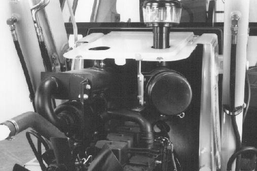
NOTE: The photo shown below does not correspond to this model of machine, but the procedure is the same.
STEP 15
Put a block under the oil cooler to hold the radiator, oil cooler, and condenser in place when the radiator shroud is removed.
STEP 16
Remove the cap screws that fasten the lower brackets (2) to the radiator (1). Remove the hardware and the lower brackets (2) from the radiator shroud. Remove the cap screws and flat washers that fasten the upper brackets (3) to the radiator.
STEP 17
Remove the studs (1) from the frame. Remove the bolts and nuts (2) that fasten the radiator shroud to the frame.
STEP 18
Remove the radiator shroud from the radiator, oil cooler, and condenser.
STEP 19
Disconnect the electrical connector for the drier.
STEP 20
Disconnect the hoses on either side of the oil cooler. Plug the hoses.
CD00C006
CD00C009
CD00C010
Remove the cap screws and flat washers that fasten the condenser and oil cooler to the radiator.
STEP 22
Pull the foam baffle away from the condenser.
STEP 23
BP9503111
For machines with a slot in the baffle plate, move the condenser and drier assembly out of the way as shown. For machines without a slot in the baffle plate, have another person help to move the condenser, baffle plate, and drier assembly away from the radiator and oil cooler assembly. Fasten the assembly in position to the side.
STEP 24
BP9503107
BP9503110
BP9503112
Remove the radiator and oil cooler. Remove the fan shroud (1) from the fan.
STEP 25
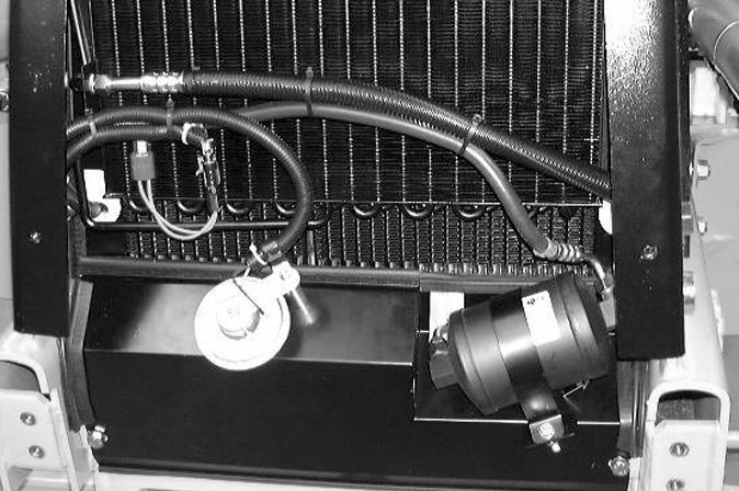
Disconnect the hoses (1) from the LH side of the pump. Loosen the clamp (2) and disconnect the hose from the RH side of the pump.
NOTE: The photo shown below does not correspond to this model of machine, but the procedure is the same.
STEP 26
Loosen and remove the cap screws that fasten the pump to the pump mounting bracket.
NOTE: Do Steps 27 to 29 for machines with air conditioning.
STEP 27
Disconnect the electrical connector (1). Remove the hardware (2) from the adjusting straps.
STEP 28
Remove the hardware that fastens the compressor to the bracket.
STEP 29
Remove the belt and place the compressor in the position shown in the photograph.
NOTE: During installation, adjust the drive belt according the instructions in Section 9003.
CD00C011
BP9502311
CD00C012
CD00C013
BP9503120
CD00C014
Loosen the clamp for the exhaust pipe at the muffler. Remove the exhaust pipe from the muffler.
NOTE: When installing, tighten the clamp to a torque of between 53 and 61 Nm.
STEP 31
Remove the electrical connectors (1) from the air filter restriction warning lamp. Loosen the air filter hose clamp (2). Disconnect the air filter hose.
STEP 32
BP9502306
Remove the cap screws and flat washers that fasten the cover to uprights. Remove the cover and air cleaner as an assembly.
STEP 33
CD00C015
Remove the tie straps (1). Disconnect the wiring harness clamp (2). Disconnect the cable from the oil pressure sender (3). Disconnect the fuel stop cable (4).
BP9502308
34
Disconnect the fuel pipe (1) and plug it.
STEP 35
Disconnect and cap the heater hose (1).
STEP 36
BP9502298
Disconnect the coolant temperature sender (1) and coolant temperature switch (2).
STEP 37
Remove the harness clamps (1). Disconnect the cables (2) from the alternator.
STEP 38
Loosen the clamp. Disconnect and plug the heater hose.
STEP 39
Disconnect the earth strap (1). Put identification tags on the starter cables (2). Disconnect the cables (2).
BP9502301
BP9502297
CD00C017
NOTE: The photo below does not correspond to this model of machine but the procedure is the same.
STEP 40
BP9502310
Remove the bolts, flat washers, and nuts from the front engine mount.
NOTE: When installing, tighten the self-locking nuts to a torque of between 41 and 47 Nm.
STEP 41
Connect lifting equipment to the lifting eyes on the engine to hold the engine in place.
NOTE: There are six cap screws with lock washers that fasten the torque converter to the flywheel. Rotate the engine to align each cap screw with the access hole in the flywheel housing at the left side of the engine.
STEP 42
Remove the plastic plug from the flywheel housing. Remove the hose from the bracket and remove the cover and gasket from the access hole for the cap screws.
STEP 43
Install the CAS1690 tool to turn the flywheel.
STEP 44
Loosen and remove all six cap screws and washers that fasten the torque converter to the flywheel.
NOTE: Be careful during installation when installing the cap screws and lock washers that fasten the torque converter to the flywheel. Tighten the screws to a torque of between 52 and 57 Nm.
STEP 45
Loosen and remove the 12 cap screws and flat washers that fasten the transmission to the engine. Move the heater hose and clamps out of the way.
Move the engine forward and raise the engine. Remove the engine from the machine.
NOTE: Installation of the engine is the reverse of removal. Before starting the engine, do the following:
1.Fill the turbocharger with oil. Disconnect the fuel shut-off solenoid cable. Operate the starter motor for 1à to 20 seconds to fill the turbo-charger with oil. Connect the wire to the fuel shut-off solenoid.
2.It is essential that the hydraulic pump is filled with oil. Carry out the following procedure to fill the hydraulic pump with oil:
A. Make sure that the oil level in the reservoir is correct.
B. Remove the cap from the hydraulic reservoir.
C. Use a compressed air nozzle to pressurize the hydraulic reservoir. Wrap a cloth around the end of the hose at the nozzle.
NOTE: 34.5 kPa to 69.0kPa is all that is required to move the oil. Pressure above 69.0 kPa can damage the hydraulic reservoir.
D. Have another person start and run the engine at low idle while the hydraulic reservoir is being pressurised.
NOTE: If there is no response to click on the link above, please download the PDF document first and then clickonit.
1RADIATOR
2FAN SHROUD
3COOLANT RECOVERY RESERVOIR
4SCREEN
5OIL COOLER
6AIR CONDITIONING CONDENSER
B9503081T
1RADIATOR SHROUD
2SCREWS RETAINING RADIATOR ON MACHINE UNDERCARRIAGE
3NUT
4BRACKET, RADIATOR SHROUD TO RADIATOR
5SCREW 6FLAT WASHER, SPECIAL 7SHOCK ABSORBER 8SPACER
CI00C508