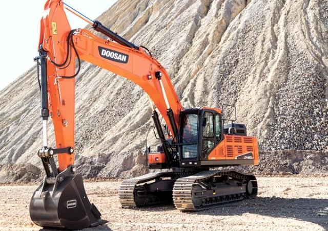
Shop Manual
K1009096AE
Serial Number 5327 and Up


Shop Manual
K1009096AE
Serial Number 5327 and Up
Doosan reserves the right to improve our products in a continuing process to provide the best possible product to the market place. These improvements can be implemented at any time with no obligation to change materials on previously sold products. It is recommended that consumers periodically contact their distributors for recent documentation on purchased equipment.
This documentation may include attachments and optional equipment that is not available in your machine's package. Please call your distributor for additional items that you may require.
Illustrations used throughout this manual are used only as a representation of the actual piece of equipment, and may vary from the actual item.
K1009096AE Shop Manual
Copyright 2008 Doosan
Safety
Track Excavator Safety.........................................................................SP000907
Specifications
Specification for DX420LC....................................................................SP001755
General Maintenance
General Maintenance Procedures........................................................SP000016
Standard Torques.................................................................................SP000813
Upper Structure Cabin....................................................................................................SP001737
Counterweight.......................................................................................SP001756
Fuel Tank..............................................................................................SP001757
Fuel Transfer Pump (Opt).....................................................................SP000021
Swing Bearing.......................................................................................SP001856
Swing Reduction Gear..........................................................................SP001740
Lower Structure and Chassis
Track Assembly....................................................................................SP000263
Engine and Drive Train
Drive Coupling (Main Pump).................................................................SP000026
Hydraulics
Hydraulic System Troubleshooting, Testing and Adjustment...............SP001758
Accumulator..........................................................................................SP000028
Center Joint (Swivel).............................................................................SP000181
Cylinders...............................................................................................SP000030
of Contents
Swing Motor..........................................................................................SP000261
Travel Motor (With Gearbox)................................................................SP000266
Main Pump............................................................................................SP000186
Gear Pump (Fan Cooling Drive)...........................................................SP000208
Main Control Valve...............................................................................SP000187
Remote Control Valve (Work Lever / Joystick).....................................SP000189
Travel Control Valve (With Damper).....................................................SP001743
Fan Motor (Vane Type).........................................................................SP000209
Fan Cooling Flow In-Out Change Valve...............................................SP000207
Solenoid Valve Assembly.....................................................................SP001622
Breaker EPPR Valve (Opt)...................................................................SP000192
Hydraulic Schematic (DX420LC)..........................................................SP001769
Electrical System
Electrical System..................................................................................SP001759
Electrical Schematic DX420LC.............................................................SP001857
Attachments
Boom and Arm......................................................................................SP001851 Bucket...................................................................................................SP001852
Table of Contents
Follow all safety recommendations and safe shop practices outlined in the front of this manual or those contained within this section.
Always use tools and equipment that are in good working order.
Use lifting and hoisting equipment capable of safely handling load.
Remember, that ultimately safety is your own personal responsibility.
The contents of this section apply to the following models and serial number ranges.
MODELSERIAL NUMBER RANGE
DX340LC5980 and Up
DX350LC5980 and Up
DX420LC5327 and Up
DX480LC5221 and Up
DX520LC5117 and Up
A8VO200LA1KH1/63
NOTE: Observe the following cautions when carrying out repairs on hydraulic units.
1.Close off all openings of hydraulic unit.
3
4
2.Replace all seals. Use only original spare parts
3.Check all sealing and sliding surfaces for wear.
NOTE: Rework of sliding surfaces using crocus cloth or other similar materials, can damage the surface.
5
6
4.Fill hydraulic unit with hydraulic oil before putting into operation.
1.Seal kit for drive shaft.
8
2.Peripheral seal kit.
Figure 9
3.Rotary group 1, ready to install.
10
4.Rotary group 2, ready to install.
11
5.Rotary group, hydraulic component (order rotary groups 1 and 2 separately).
NOTE: Adjustment is necessary. Pay attention to direction of rotation.
6.Rotary group 1, mechanical section, ready to install.
12
7.Rotary group 2, mechanical section, ready to install.
13
14
8.Control, pre-adjusted.
15
9.Gear pump, complete.
Figure 16
10.Intermediate gear.
Figure 17
11.Auxiliary drive.
18
12.Valve plate with valves.
19
13.Pipe, complete with fittings.
20
21
1.Protect drive shaft. (e.g. with tape).
22
2.Remove retaining ring and shim.
23
3.Screw sheet metal screw(s) into holes fitted with rubber.
Pull out seal with pliers.
4.Press in shaft seal ring and shim with bushing to stop.
NOTE: Take note of press-in depth. Install mark for press-in depth of safety ring.
24
25
26
Remove gear pump.
Visually check: 1.O-ring (1, Figure 27).
2.Sealing surface of housing (2, Figure 28).
1.Place pump into a disassembly / assembly device with a crane and secure it into position.
2.Remove screws holding port plate.
3.Using a suitable lifting device, remove port plate.
NOTE: Mark installation position.
NOTE: Be careful, control lenses can fall out.
30
31
4.Remove paper seal, and clean sealing surface.
NumberDescription
1Setting Screw: Q max
2Setting Screw: Hydraulic Stroke Limitation
3Setting Screw: Power Characteristic (Begin of Regulation)
NOTE: Before carrying out setting or disassembly of regulator, measure distance "X" of adjustment screw and record value.
Figure 35
Remove and disassemble control module LR.
Remove and disassemble control module H.
39
1.Remove cover.
NOTE: Do not change the setting of adjustment screw (1, Figure 39).
40
2.Remove screws.
NOTE: Install control lens - torque support.
3.Remove locking screw and replace with a new one.
NOTE: Loosen adhesive with a "gentle" flame (approximately 120 °C).
41
42
4.Remove swivel pin.
43
44