Link Product / Engine
Product Market Product Engine 570ST Four - Wheel Drive 72kW T ier Side shift Asia Pacific 570ST T - Wheel Drive 72kW T ier Side shift Latin America 8045.45.748 570ST T - Wheel Drive (2WD), 72kW T ier Side shift Australia New Zealand 570ST Four - Wheel Drive 72kW T ier Side shift Latin America 570ST Four - Wheel Drive (4WD), 72kW T ier Side shift Middle East Africa 8045.45.748 570ST T - Wheel Drive (2WD), 72kW T ier Side shift Asia Pacific 570ST T - Wheel Drive 72kW T ier Side shift Middle East Africa 570ST Four - Wheel Drive (4WD), 72kW T ier Side shift Australia New Zealand 8045.45.748 48048556 16/09/2016
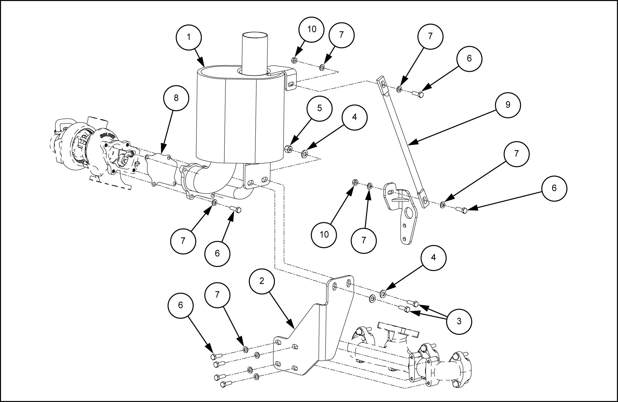
[10.254] Intake and exhaust manifolds and muf fler
cooling system
Power shuttle transmission external controls Power shuttle transmission internal components
Powered rear axle
Rear bevel gear set and dif ferential
Final drive steering and shafts
Brakes and controls
Contents INTRODUCTION Engine . . . . . . . . . . . . . . . . . . . . . . . . . . . . . . . . . . . . . . . . . . . . . . . . . . . . . . . . . . . . . . . . . . . . . . . . . . . . . . . . . . . . . . . [10.001] Engine
. . . . . . . . . . . . . . . . . . . . . . . . . . . . . . . . . . . . . . . . . . . . . . . . . . . . . . . . . . . . . 10.1
. . . . . . . . . . . . . . . . . . . . . . . . . . . . . . . . . . . . . . . . . 10.2
. . . . . . . . . . . . . . . . . . . . . . . . . . . . . . . . . . . . . . . . . . . . . . . . . . . . . . . . . . . . . 10.3
and crankcase
[10.400] Engine
ransmission . . . . . . . . . . . . . . . . . . . . . . . . . . . . . . . . . . . . . . . . . . . . . . . . . . . . . . . . . . . . . . . . . . . . . . . . . . . . . .
Power
TMechanical transmission lubrication system 12]
shuttle transmission
T
Front axle system . . . . . . . . . . . . . . . . . . . . . . . . . . . . . . . . . . . . . . . . . . . . . . . . . . . . . . . . . . . . . . . . . . . . . . . Powered
axle Front bevel gear set and dif ferential [25.108] Final drive hub, steering knuckles, and shafts . . . . . . . . . . . . . . . . . . . . . . . . . . . . . . . . . . . . . 25.3 [25.400] Non-powered front axle . . . . . . . . . . . . . . . . . . . . . . . . . . . . . . . . . . . . . . . . . . . . . . . . . . . . . . . . . . . . 25.4 Rear axle
. . . . . . . . . . . . . . . . . . . . . . . . . . . . . . . . . . . . . . . . . . . . . . . . . . . . . . . . . . . . . . . . . . . . . . . .
orque converter
front
system
. . . . . . . . . . . . . . . . . . . . . . . . . . . . . . . . . . . . . . . . . . . . . . . . . . . . . . . . . . . . . . . . . . . . [33.202] Hydraulic
. . . . . . . . . . . . . . . . . . . . . . . . . . . . . . . . . . . . . . . . . . . . . . . . . . . . . . . . . . . 33.1 [33.1 10] Parking brake parking lock . . . . . . . . . . . . . . . . . . . . . . . . . . . . . . . . . . . . . . . . . . . . . . . . . . . . . . 33.2 Hydraulic systems . . . . . . . . . . . . . . . . . . . . . . . . . . . . . . . . . . . . . . . . . . . . . . . . . . . . . . . . . . . . . . . . . . . . . . . Hydraulic systems Reservoir , cooler , and filters 48048556 16/09/2016
service brakes
Fixed displacement pump Main control valve [35.724] Front loader hydraulic system control . . . . . . . . . . . . . . . . . . . . . . . . . . . . . . . . . . . . . . . . . . . . . . 35.5 [35.701] Front loader arm hydraulic system . . . . . . . . . . . . . . . . . . . . . . . . . . . . . . . . . . . . . . . . . . . . . . . . . 35.6 [35.723] Front loader bucket hydraulic system . . . . . . . . . . . . . . . . . . . . . . . . . . . . . . . . . . . . . . . . . . . . . . 35.7 [35.726] Excavator and backhoe hydraulic controls . . . . . . . . . . . . . . . . . . . . . . . . . . . . . . . . . . . . . . . . . 35.8 [35.736] Boom hydraulic system . . . . . . . . . . . . . . . . . . . . . . . . . . . . . . . . . . . . . . . . . . . . . . . . . . . . . . . . . . . . 35.9 [35.737] Dipper hydraulic system . . . . . . . . . . . . . . . . . . . . . . . . . . . . . . . . . . . . . . . . . . . . . . . . . . . . . . . . . . 35.10 [35.738] Excavator and backhoe bucket hydraulic system . . . . . . . . . . . . . . . . . . . . . . . . . . . . . . . . 35.1 1 Swing arm hydraulic system Hydraulic systems generic Frames and ballasting [39.129] Stabilizers . . . . . . . . . . . . . . . . . . . . . . . . . . . . . . . . . . . . . . . . . . . . . . . . . . . . . . . . . . . . . . . . . . . . . . . . . . 39.1 Steering . . . . . . . . . . . . . . . . . . . . . . . . . . . . . . . . . . . . . . . . . . . . . . . . . . . . . . . . . . . . . . . . . . . . . . . . . . . . . . . . . . . . . Steering control Hydraulic control components Cylinders Wheels . . . . . . . . . . . . . . . . . . . . . . . . . . . . . . . . . . . . . . . . . . . . . . . . . . . . . . . . . . . . . . . . . . . . . . . . . . . . . . . . . . . . . . [44.51 Front wheels . . . . . . . . . . . . . . . . . . . . . . . . . . . . . . . . . . . . . . . . . . . . . . . . . . . . . . . . . . . . . . . . . . . . . . . . 44.1 [44.520] Rear wheels . . . . . . . . . . . . . . . . . . . . . . . . . . . . . . . . . . . . . . . . . . . . . . . . . . . . . . . . . . . . . . . . . . . . . . . . 44.2 [44.AAA] Wheels generic sub-group . . . . . . . . . . . . . . . . . . . . . . . . . . . . . . . . . . . . . . . . . . . . . . . . . . . . . . . . 44.3 Cab climate control . . . . . . . . . . . . . . . . . . . . . . . . . . . . . . . . . . . . . . . . . . . . . . . . . . . . . . . . . . . . . . . . . . . . . Heating Air conditioning Electrical systems . . . . . . . . . . . . . . . . . . . . . . . . . . . . . . . . . . . . . . . . . . . . . . . . . . . . . . . . . . . . . . . . . . . . . . . [55.100] Harnesses and connectors . . . . . . . . . . . . . . . . . . . . . . . . . . . . . . . . . . . . . . . . . . . . . . . . . . . . . . . . . 55.1 [55.201] Engine starting system . . . . . . . . . . . . . . . . . . . . . . . . . . . . . . . . . . . . . . . . . . . . . . . . . . . . . . . . . . . . . 55.2 [55.301] Alternator . . . . . . . . . . . . . . . . . . . . . . . . . . . . . . . . . . . . . . . . . . . . . . . . . . . . . . . . . . . . . . . . . . . . . . . . . . . 55.3 48048556 16/09/2016
Wiper and washer system Front loader and bucket [82.100] Arm . . . . . . . . . . . . . . . . . . . . . . . . . . . . . . . . . . . . . . . . . . . . . . . . . . . . . . . . . . . . . . . . . . . . . . . . . . . . . . . . . 82.1 [82.300] Bucket . . . . . . . . . . . . . . . . . . . . . . . . . . . . . . . . . . . . . . . . . . . . . . . . . . . . . . . . . . . . . . . . . . . . . . . . . . . . . . 82.2 Booms, dippers, and buckets . . . . . . . . . . . . . . . . . . . . . . . . . . . . . . . . . . . . . . . . . . . . . . . . . . . . . . . [84.1 14] Boom pivoting support . . . . . . . . . . . . . . . . . . . . . . . . . . . . . . . . . . . . . . . . . . . . . . . . . . . . . . . . . . . . . 84.1 [84.910] Boom . . . . . . . . . . . . . . . . . . . . . . . . . . . . . . . . . . . . . . . . . . . . . . . . . . . . . . . . . . . . . . . . . . . . . . . . . . . . . . . 84.2 [84.912] Dipper arm . . . . . . . . . . . . . . . . . . . . . . . . . . . . . . . . . . . . . . . . . . . . . . . . . . . . . . . . . . . . . . . . . . . . . . . . . 84.3 Platform, cab, bodywork, and decals . . . . . . . . . . . . . . . . . . . . . . . . . . . . . . . . . . . . . . . . . . . . . Cab Cab doors and hatches Cab windshield and windows [90.100] Engine hood and panels . . . . . . . . . . . . . . . . . . . . . . . . . . . . . . . . . . . . . . . . . . . . . . . . . . . . . . . . . . . 90.4 48048556 16/09/2016
48048556 16/09/2016

INTRODUCTION 48048556 16/09/2016 1
Contents INTRODUCTION Safety rules (*) . . . . . . . . . . . . . . . . . . . . . . . . . . . . . . . . . . . . . . . . . . . . . . . . . . . . . . . . . . . . . . . . . . . . . . . . . . . . . . . . . . 3 Safety rules (*) . . . . . . . . . . . . . . . . . . . . . . . . . . . . . . . . . . . . . . . . . . . . . . . . . . . . . . . . . . . . . . . . . . . . . . . . . . . . . . . . . . 4 Safety rules - Ductile iron (*) . . . . . . . . . . . . . . . . . . . . . . . . . . . . . . . . . . . . . . . . . . . . . . . . . . . . . . . . . . . . . . . . . . . . 5 Safety rules - Ductile iron (*) . . . . . . . . . . . . . . . . . . . . . . . . . . . . . . . . . . . . . . . . . . . . . . . . . . . . . . . . . . . . . . . . . . . . 6 Safety rules (*) . . . . . . . . . . . . . . . . . . . . . . . . . . . . . . . . . . . . . . . . . . . . . . . . . . . . . . . . . . . . . . . . . . . . . . . . . . . . . . . . . . 7 Safety rules - Ecology and the environment (*) . . . . . . . . . . . . . . . . . . . . . . . . . . . . . . . . . . . . . . . . . . . . . . . . . 8 Basic instructions - Important notice regarding equipment servicing (*) . . . . . . . . . . . . . . . . . . . . . . . . 9 Basic instructions (*) . . . . . . . . . . . . . . . . . . . . . . . . . . . . . . . . . . . . . . . . . . . . . . . . . . . . . . . . . . . . . . . . . . . . . . . . . . Basic instructions - Fuse and relay locations (*) . . . . . . . . . . . . . . . . . . . . . . . . . . . . . . . . . . . . . . . . . . . . . . 1 1 Basic instructions (*) Basic instructions (*) Basic instructions - Shop and assembly (*) Basic instructions - Minimum tightening torques for normal assembly (*) T orque - Standard torque data for hydraulics (*) Abbreviation - Measurements (*) Capacities (*) (*) See content for specific models 48048556 16/09/2016 2
Safety rules
570ST ANZ - - - - - - - - - MEA
Personal safety
This the safety alert used alert you potential personal injury
Obey all safety messages that follow this symbol avoid possible death injury .

Throughout this manual you will find the signal words W and CAUTION followed special These precautions are intended for the personal safety you and those working with
Read and understand all the safety messages this manual before you operate service the
DANGER indicates a hazardous situation not will result death serious injury
W ARNING indicates a hazardous situation not could result death serious injury
CAUTION indicates a hazardous situation that, not avoided, could result minor moderate injury .
F AILURE T O FOLLOW DANGER, W ARNING, AND CAUTION MESSAGES COULD RESUL T DEA SERIOUS INJUR Y .
Machine safety
NOTICE: Notice indicates a situation not could result machine property
Throughout this manual you will find the signal word Notice followed special instructions prevent machine property The word Notice used address practices not related personal safety
Information
NOTE: Note indicates additional information that clarifies other information this
Throughout this manual you will find the word Note followed additional information about a other information the The word Note not intended address personal safety property
INTRODUCTION
48048556 16/09/2016 3
INTRODUCTION
Safety rules
570ST ANZ - - - -
DANGER
MEA
Improper operation service this machine can result accident. not operate this machine perform any repair until you have read and understood the operation, lubrication, maintenance, and repair information. Failure comply will result death serious injury D0010A
W ARNING
Maintenance hazard!
Always perform all service procedures punctually the intervals stated this manual. This ensures optimum performance levels and maximum safety during machine operation. Failure comply could result death serious injury . W0132A
NOTICE: Extreme working and environmental conditions require shortened service

Use Case and filters for the best protection and performance your All and filters must disposed compliance with environmental standards and Contact your Dealer with any questions regarding the service and maintenance this machine.
Use this manual with the manual understand and perform the complete service Read the safety decals and information decals the machine. Read the Operator ’ s Manual and safety manual. Understand the operation the machine before you start any
Before you service the put a Not tag the steering wheel over the key Ensure the tag a location where everyone who might operate service the machine may see clearly
Plastic and resin parts
• A void using paint thinner , when cleaning plastic instrument cluster ,
• Use only water , mild and a soft cloth when you clean these
• Using can cause deformation the part being
48048556
- - - - -
16/09/2016 4
Safety rules - Ductile iron

DANGER
Altering cast ductile iron can cause weaken break.
Before you weld, cut, drill holes any part this machine, make sure that the part not cast ductile Failure comply will result death serious injury .
Unauthorized modifications cast ductile iron parts can cause death serious injury . not weld, cut, drill, repair , attach items cast ductile iron parts this machine.
Altering cast ductile iron can cause weaken
Before you drill holes any part this make sure the part not cast ductile See your dealer you not know a part cast ductile
The following items are examples cast ductile iron There may also other parts made cast ductile iron that are not the list below
• two - wheel drive steering link
• dump links
• front axle
• stabilizers
• extend - a - hoe
• swing tower
• bucket linkage
• Air - Conditioning / compressor mounting bracket not make any unauthorized Consult authorized dealer before making any modifications this
INTRODUCTION
570ST ANZ - - - - - - - - - MEA
D0148A
48048556 16/09/2016 5
Safety rules - Ductile iron
DANGER
Improper operation service this machine can result accident. Any unauthorized modifications made this machine can have serious consequences. Consult authorized dealer modifications that may required for this not make any unauthorized modifications.
Failure comply will result death serious injury
D0030A
Before you weld, cut, drill holes any part this machine, make sure the part not cast ductile iron. See your dealer you not know a part cast ductile The following are cast ductile iron parts:
• two wheel drive steering link
• dump links
• front axle
• stabilizers
• extendahoe
• swing
• bucket linkage
• Air Conditioning / compressor mounting bracket
Unauthorized modifications cast ductile iron parts can cause injury W drilling can cause cast ductile iron break. not weld, cut, drill repair attach items cast ductile iron parts this machine.
INTRODUCTION
570ST ANZ - - - - - - - - - MEA
48048556 16/09/2016 6
Safety rules
570ST ANZ - - - - - - - - - MEA
Unless otherwise always perform these steps before you service the machine: Park the machine a level
Place the backhoe the transport position with the swing lock pin installed for Place the loader bucket the with the bottom the loader bucket parallel the Place the direction control lever and the transmission you need open the hood perform raise the loader arms and install the support Shut down the
Place a Not tag the key switch that visible other workers remove the key
INTRODUCTION
48048556 16/09/2016 7
Safety rules - Ecology and the environment
air , and water are vital factors agriculture and life When legislation does not yet rule the treatment some the substances required advanced technology , sound judgment should govern the use and disposal products a chemical and petrochemical nature.
NOTE: The following are recommendations that may assistance:
• Become acquainted with and ensure that you understand the relative legislation applicable your country
• Where legislation obtain information from suppliers cleaning with regard their fect man and nature and how safely and dispose these substances.
Helpful hints
• A void filling tanks using cans inappropriate pressurized fuel delivery systems that may cause considerable
• avoid skin contact with all
Most them contain substances that may harmful your
• Modern oils contain not burn contaminated fuels and waste oils ordinary heating
• A void spillage when draining f used engine coolant gearbox and hydraulic brake not mix drained brake fluids fuels with Store them safely until they can disposed a proper way comply with local legislation and available resources.
• Modern coolant antifreeze and other should replaced every two They should not allowed get into the but should collected and disposed properly
• Repair any leaks defects the engine cooling hydraulic system immediately
• not increase the pressure a pressurized circuit this may lead a component
• Protect hoses during welding penetrating weld splatter may burn a hole weaken allowing the loss 48048556
INTRODUCTION
- - - - - - -
570ST ANZ - -
MEA
16/09/2016 8
Basic instructions - Important notice regarding equipment servicing
All repair and maintenance work listed this manual must carried out only qualified dealership strictly complying with the instructions and whenever the special
Anyone who performs repair and maintenance operations without complying with the procedures provided herein shall responsible for any subsequent
The manufacturer and all the organizations its distribution including - without limitationlocal CASE reject any responsibility for damages caused parts and / components not approved the manufacturer , including those used for the servicing repair the product manufactured marketed the manufacturer
any case, warranty given attributed the product manufactured marketed the manufacturer case damages caused parts and / components not approved the manufacturer
The information this manual - - date the date the publication. the policy the manufacturer for continuous Some information could not updated due modifications a technical commercial changes the laws and regulations dif ferent
case refer your Case New Holland Construction Equipments Sales and Service
INTRODUCTION
570ST ANZ - - - - - - - - - MEA
48048556 16/09/2016 9
Basic instructions
570ST ANZ
W ARNING
Explosive gas!
MEA
Batteries emit explosive hydrogen gas and other fumes while charging. V entilate the charging area. Keep the battery away from sparks, open flames, and other ignition sources. Never charge a frozen battery
Failure comply could result death serious injury .
W ARNING
Hazardous chemicals!
W0005A
Battery electrolyte contains sulfuric acid. Contact with skin and eyes could result severe irritation and burns. Always wear splash - proof goggles and protective clothing (gloves and aprons). W ash hands after
Failure comply could result death serious injury .
• not run the engine with the alternator wires
• Before using electric welder , disconnect the alternator wires, instrument cluster and batteries.
• not use a steam cleaner a cleaning solvent clean the alternator
• Keep the battery vents clean. Ensure the battery vents are not restricted.
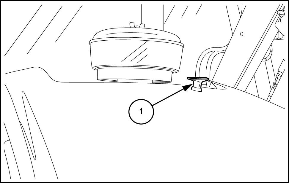
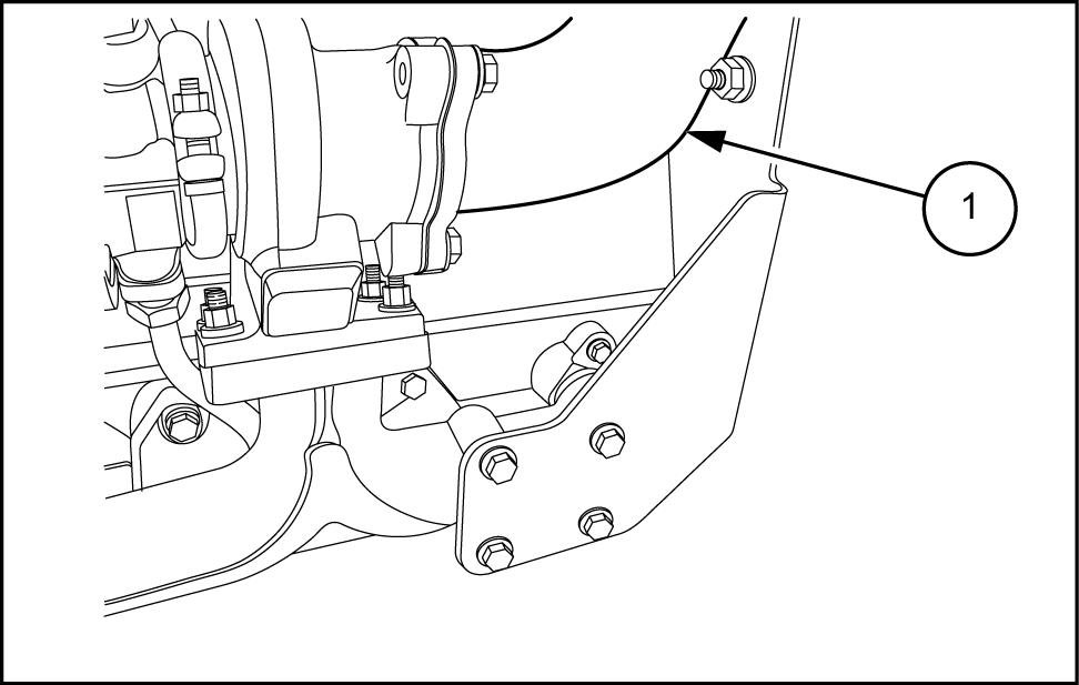
Disconnect battery
Open the battery compartment cover the right hand side step the using the key
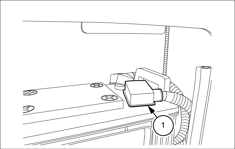
Disconnect the negative battery cable (1) from the negative battery
W0006A
INTRODUCTION
- - - - - - - - -
PTIL13TLB1 199AB 1 48048556 16/09/2016
Basic instructions - Fuse and relay locations
The machine equipped with a fuse located the side
Side console box
T urn the thumb screws (1) loosen the panel cover (2) for the fuse Remove the panel cover
Remove the fuse box covers
Refer the decal top the panel cover for relay , and / diode
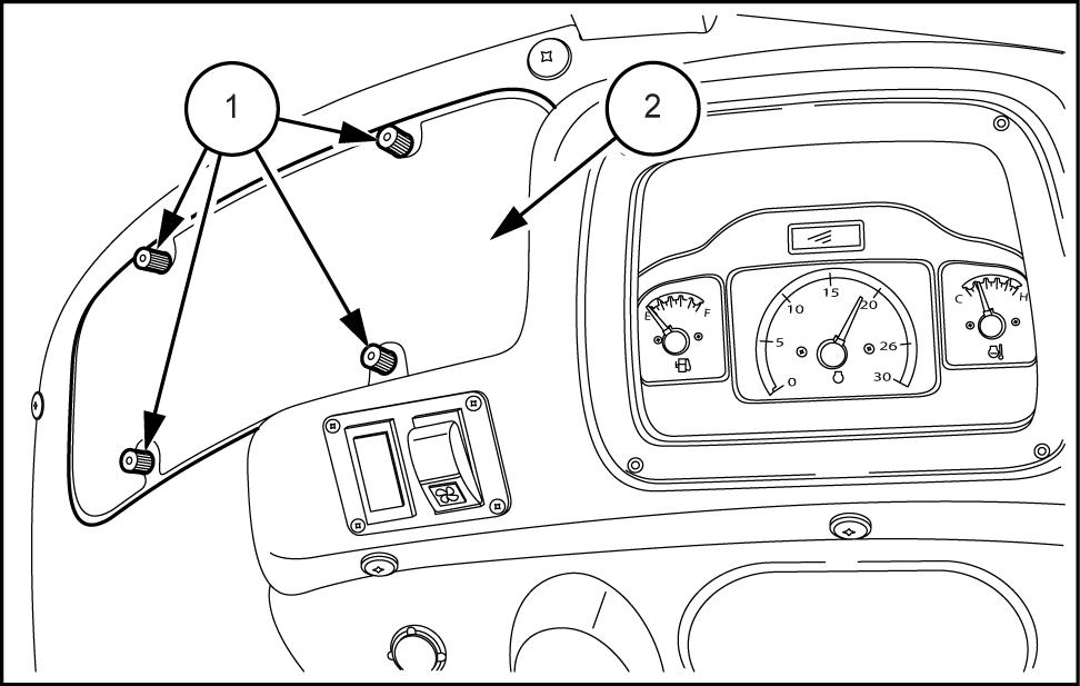
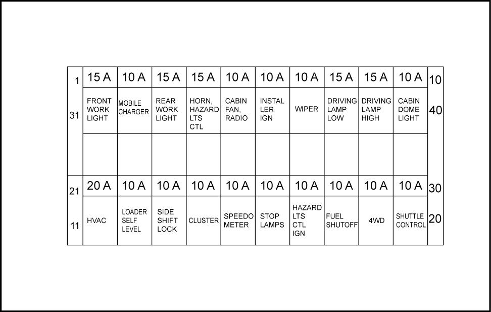
The fuses are arranged per the Fig. 2
INTRODUCTION
570ST ANZ - - - - - - - - - MEA
No. Fuse rating Fuse details 1 A Front work light 2 A V power output 3 A Rear work light 4 A hazard light control 5 A radio 6 A Installer ignition 7 A Wiper 8 A Driving lamp LOW 9 A Driving lamp HIGH A Cabin dome light 1 1 A (If fitted) A Loader self level A Side shift lock A Cluster A Speedometer A Stop lamps A Hazard lights control ignition A Fuel shutof f A 4WD (If fitted) A Shuttle control
PTIL12TLB0441AA 2 48048556 16/09/2016 1 1
PTIL13TLB0302AB 1
INTRODUCTION
Basic instructions
570ST ANZ
W ARNING
Crushing hazard!
MEA
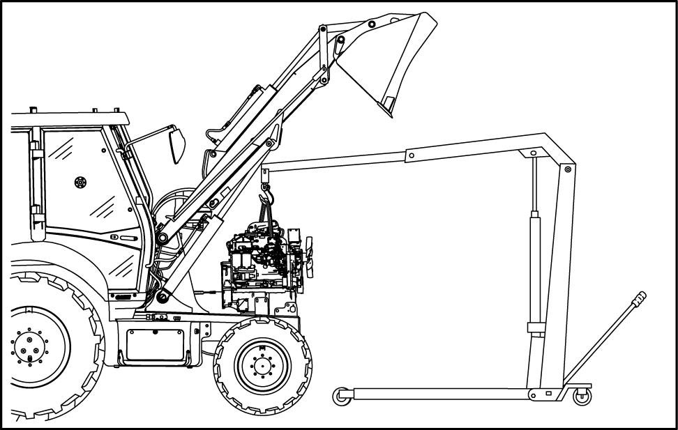
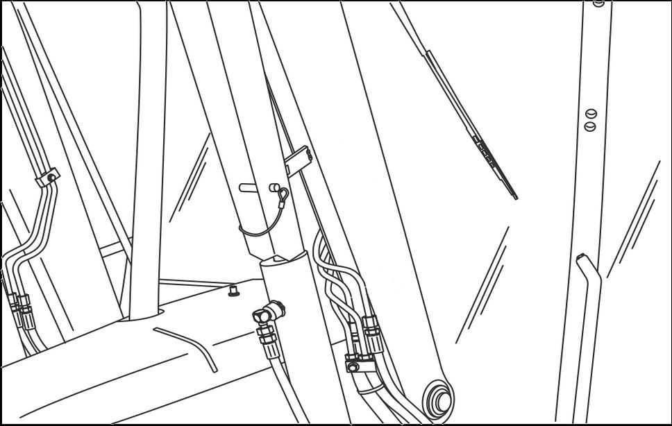
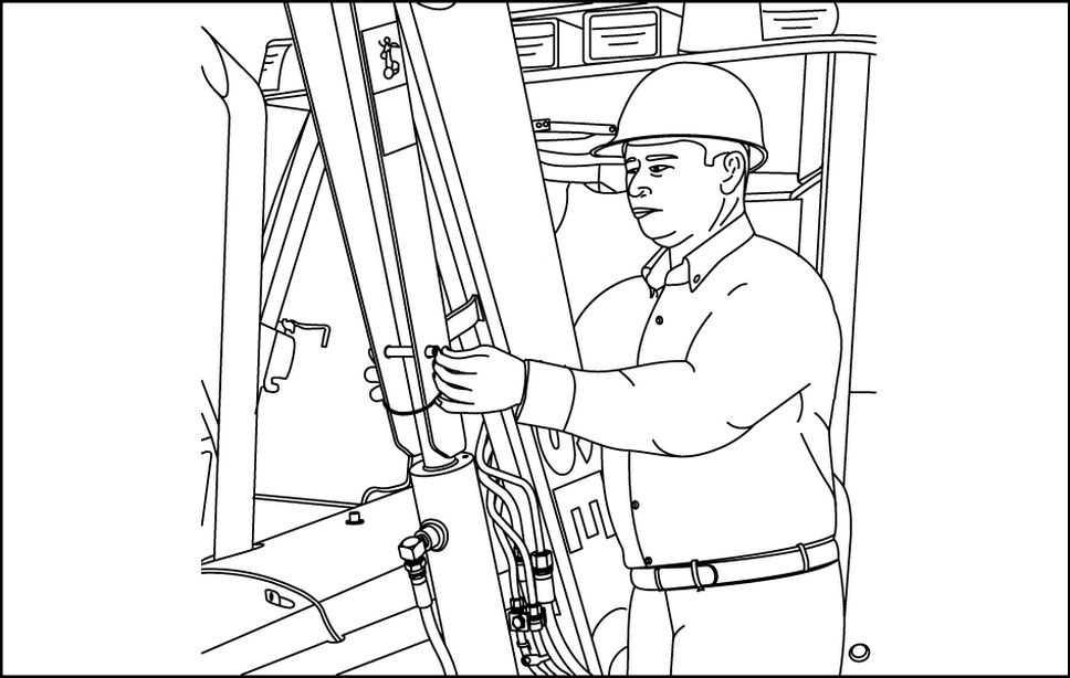
you service the machine with the loader lift arms raised, always use the support strut. Remove the retaining pin and place the support strut onto the cylinder rod. Install the retaining pin into the support Lower the lift arms onto the support
Failure comply could result death serious injury .
Raise and support loader lift arms:
Empty the loader bucket.
Raise the loader lift arms the maximum Shut down the engine.
RCPH10TLB230AAF 1
Remove the retaining
Lower the support strut onto the cylinder
Install the retaining
RCPH10TLB221AAF 2
Start the
Slowly lower the lift arms that the end the support strut rests the cylinder
RCPH10TLB227AAF 3 48048556
W0230A
- - - - - - - - -
16/09/2016
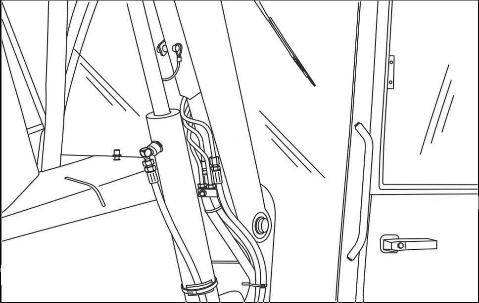
Lower supported loader lift arms:
Raise the lift arms that the end the support strut longer rests the cylinder
Shut down the engine.
Remove the retaining pin from the support
Raise the support strut the storage position and secure with the retaining
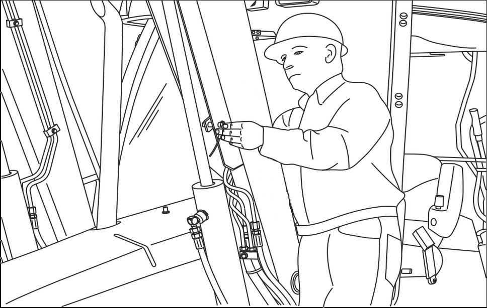
Start the
Lower the loader the
INTRODUCTION
RCPH10TLB227AAF 4
RCPH10TLB231AAF 5
48048556 16/09/2016
INTRODUCTION
Basic instructions
570ST ANZ
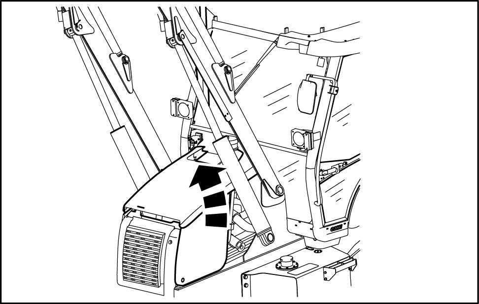
Open the hood: Shut down the engine.
T urn the handle (1) counter - clockwise release the hood
MEA
PTIL13TLB1558AB 1
Lift the hood and rotate
PTIL12TLB0559AB 2
NOTICE: T o avoid damage the hood always close the hood before moving the loader
Close the hood:
Lower the
T urn the handle (1) clockwise lock the hood latch.
PTIL13TLB1558AB 3 48048556
- - - - - - - - -
16/09/2016
Basic instructions - Shop and assembly
570ST ANZ -
Shimming
For each adjustment select adjusting shims and measure the adjusting shims individually using a eter , then add the recorded not rely measuring the entire shimming set, which may the rated value shown each
Rotating shaft seals
For correct rotating shaft seal proceed follows: Before assembly , allow the seal soak the oil will sealing for least thirty minutes.
Thoroughly clean the shaft and check that the working surface the shaft not Position the sealing lip facing the fluid.
NOTE: W ith hydrodynamic lips, take into consideration the shaft rotation direction and position the grooves that they will move the fluid towards the inner side the
Coat the sealing lip with a thin layer lubricant (use oil rather than grease). Fill the gap between the sealing lip and the dust lip double lip seals with
Insert the seal its seat and press down using a flat punch seal installation not tap the seal with a hammer
While you insert the check that the seal perpendicular the When the seal make sure that the seal makes contact with the thrust element, required.
T o prevent damage the seal lip the position a protective guard during installation O - ring seals
Lubricate the O - ring seals before you insert them the This will prevent the O - ring seals from overturning and twisting, which would jeopardize sealing ficiency .
Sealing compounds
Apply a sealing compound the mating surfaces when specified the procedure. Before you apply the sealing prepare the surfaces directed the product container
Spare parts
Only use CNH Original Parts CASE CONSTRUCTION Original
Only genuine spare parts guarantee the same quality , duration, and safety original parts, they are the same parts that are assembled during standard Only CNH Original Parts CASE CONSTRUCTION Original
Parts can fer this
When ordering spare always provide the following information:
• Machine model (commercial name) and Product Identification Number (PIN)
• Part number the ordered which can found the parts catalog
INTRODUCTION
- - - - - - -
-
MEA
48048556 16/09/2016
Protecting the electronic and / electrical systems during charging and welding
T o avoid damage the electronic and / electrical systems, always observe the following practices: Never make break any the charging circuit connections when the engine including the battery
Never short any the charging components
Always disconnect the ground cable from the battery before arc welding the machine any machine
• Position the welder ground clamp close the welding area
• you weld close proximity a computer then you should remove the module from the
• Never allow welding cables lie near , across any electrical wiring electronic component while you weld.
Always disconnect the negative cable from the battery when charging the battery the machine with a battery charger
NOTICE: you must weld the unit, you must disconnect the battery ground cable from the machine battery . The electronic monitoring system and charging system will damaged this not
Remove the battery ground Reconnect the cable when you complete
Special tools
W ARNING
Battery acid causes burns. Batteries contain sulfuric acid.
A void contact with skin, eyes clothing. Antidote (external): Flush with water . Antidote (eyes): flush with water for minutes and seek medical attention immediately Antidote (internal): Drink large quantities water milk. not induce vomiting. Seek medical attention immediately . Failure comply could result death serious injury
The special tools that CASE CONSTRUCTION suggests and illustrate this manual have been specifically searched and designed for use with CASE CONSTRUCTION The special tools are essential for reliable repair The special tools are accurately built and rigorously tested fer ficient and long - lasting ation.
using these repair personnel will benefit from:
• Operating optimal technical conditions
• Obtaining the best results
• Saving time and fort
• W orking safe conditions
INTRODUCTION
W01 1
48048556 16/09/2016
INTRODUCTION
Basic instructions - Minimum tightening torques for normal assembly
570ST ANZ - - - - - - - - - MEA
ARE NOM. SIZE CLASS 8.8 BOL T and CLASS 8 NUT CLASS 10.9 BOL T and CLASS NUT LOCKNUT CL.8 W / CL8.8 BOL T LOCKNUT CL.10 W / CL10.9 BOL T UNPLA TED PLA TED W / ZnCr UNPLA TED PLA TED W / ZnCr 2.2 N·m ( ) 2.9 N·m ( ) 3.2 N·m ( ) 4.2 N·m ( ) 2 ( ) 2.9 N·m ( ) 4.5 N·m ( ) 5.9 N·m ( ) 6.4 N·m ( ) 8.5 N·m ( ) 4 ( ) 5.8 N·m ( ) 7.5 ( ) ( ) 1 1 ( ) ( 128 ) 6.8 ( ) ( ) ( 163 ) ( 217 ) ( 234 ) ( 1 ) ( 151 ) ( 212 ) M10 N·m ( ) N·m ( ) N·m ( ) N·m ( ) N·m ( ) N·m ( ) M12 N·m ( ) N·m ( ) N·m ( ) 121 N·m ( ) N·m ( ) N·m ( ) M16 158 N·m ( 1 ) 210 N·m ( 155 ) 225 N·m ( 166 ) 301 N·m ( 222 ) 143 N·m ( 106 ) 205 N·m ( 151 ) M20 319 N·m ( 235 ) 425 N·m ( 313 ) 440 N·m ( 325 ) 587 N·m ( 433 ) 290 N·m ( 214 ) 400 N·m ( 295 ) M24 551 N·m ( 410 ) 735 N·m ( 500 ) 762 N·m ( 560 ) 1016 N·m ( 750 ) 501 N·m ( 370 ) 693 N·m ( 510 ) NOTE: through hardware torque specifications are shown pound - M10 through M24 hardware torque specifications are shown pound48048556 16/09/2016
METRIC NON - FLANGED HARDW
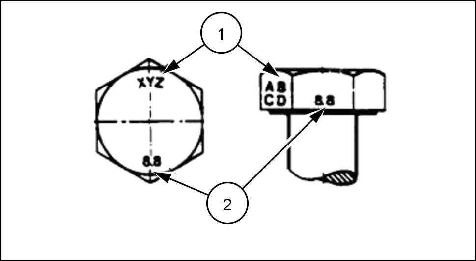
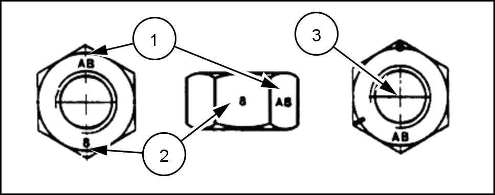
INTRODUCTION METRIC FLANGED HARDW ARE NOM. SIZE CLASS 8.8 BOL T and CLASS 8 NUT CLASS 10.9 BOL T and CLASS NUT LOCKNUT CL.8 W / CL8.8 BOL T LOCKNUT CL.10 W / CL10.9 BOL T UNPLA TED PLA TED W / ZnCr UNPLA TED PLA TED W / ZnCr 2.4 N·m ( ) 3.2 N·m ( ) 3.5 N·m ( ) 4.6 N·m ( ) 2.2 N·m ( ) 3.1 N·m ( ) 4.9 N·m ( ) 6.5 N·m ( ) 7.0 N·m ( ) 9.4 N·m ( ) 4.4 N·m ( ) 6.4 N·m ( ) 8.3 ( ) 1 1 ( ) ( 105 ) ( 141 ) 7.5 ( ) 1 1 ( ) ( 179 ) ( 240 ) ( 257 ) ( 343 ) ( 163 ) ( 240 ) M10 N·m ( ) N·m ( ) N·m ( ) N·m ( ) N·m ( ) N·m ( ) M12 N·m ( ) N·m ( ) 100 N·m ( ) 134 N·m ( ) N·m ( ) N·m ( ) M16 174 N·m ( 128 ) 231 N·m ( 171 ) 248 N·m ( 183 ) 331 N·m ( 244 ) 158 N·m ( 1 ) 226 N·m ( 167 ) M20 350 N·m ( 259 ) 467 N·m ( 345 ) 484 N·m ( 357 ) 645 N·m ( 476 ) 318 N·m ( 235 ) 440 N·m ( 325 ) M24 607 N·m ( 447 ) 809 N·m ( 597 ) 838 N·m ( 618 ) 1 1 N·m ( 824 ) 552 N·m ( 407 ) IDENTIFICA TION Metric Hex head and carriage bolts, classes 5.6 and 20083680 1 Identification Property Class Metric Hex nuts and locknuts, classes and 20083681 2 48048556 16/09/2016
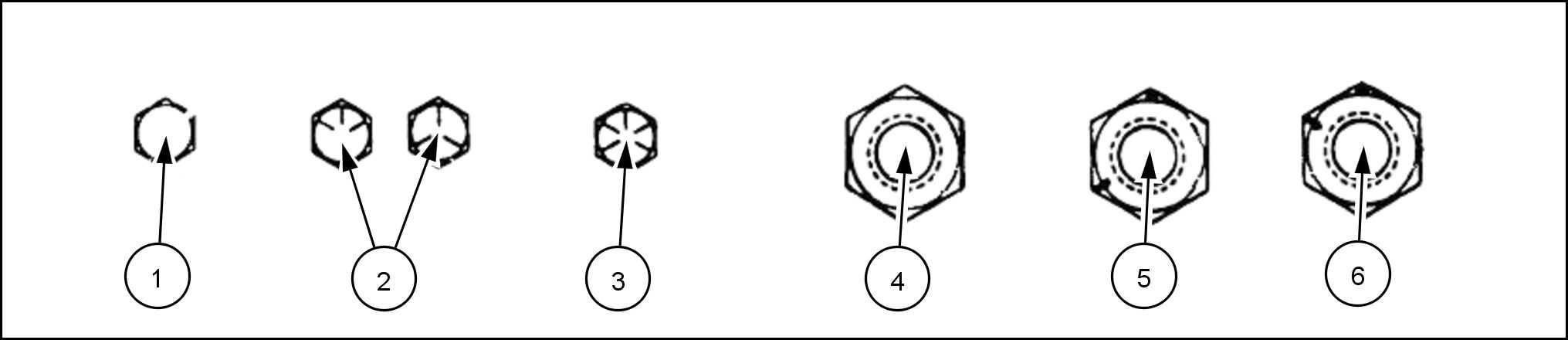
INTRODUCTION Identification Property Class Clock Marking Property Class and Identification marks ° apart indicate Class and marks 120 ° apart indicate Class INCH NON - FLANGED HARDW ARE NOMINAL SIZE SAE GRADE 5 BOL T and NUT SAE GRADE 8 BOL T and NUT LOCKNUT GrB W / Gr5 BOL T LOCKNUT GrC W / Gr8 BOL T UNPLA TED PLA TED SIL VER PLA TED W / ZnCr GOLD UNPLA TED PLA TED SIL VER PLA TED W / ZnCr GOLD 1 / 4 8 N·m ( ) 1 1 N·m ( ) ( 106 ) ( 142 ) 8.5 ( ) 12.2 N·m ( 109 ) 5 / ( 150 ) ( 204 ) ( 212 ) ( 283 ) 17.5 ( 155 ) ( 220 ) 3 / 8 ( ) ( ) ( ) ( ) N·m ( ) N·m ( ) 7 / N·m ( ) N·m ( ) N·m ( ) N·m ( ) N·m ( ) N·m ( ) 1 / 2 N·m ( ) N·m ( ) 104 N·m ( ) 139 N·m ( 103 ) N·m ( ) 108 N·m ( ) 9 / 107 N·m ( ) 142 N·m ( 105 ) 150 N·m ( 1 1 1 ) 201 N·m ( 148 ) 1 1 1 N·m ( ) 156 N·m ( 1 ) 5 / 8 147 N·m ( 108 ) 196 N·m ( 145 ) 208 N·m ( 153 ) 277 N·m ( 204 ) 153 N·m ( 1 ) 215 N·m ( 159 ) 3 / 4 261 N·m ( 193 ) 348 N·m ( 257 ) 369 N·m ( 272 ) 491 N·m ( 362 ) 271 N·m ( 200 ) 383 N·m ( 282 ) 7 / 8 420 ( 310 ) 561 ( 413 ) 594 ( 438 ) 791 ( 584 ) 437 N·m ( 323 ) 617 N·m ( 455 ) 1 630 ( 465 ) 841 ( 620 ) 890 ( 656 ) 1 187 ( 875 ) 654 ( 483 ) 924 ( 681 ) NOTE: For Imperial 1 / 4 and 5 / hardware torque specifications are shown pound - 3 / 8 through 1 hardware torque specifications are shown pound48048556 16/09/2016
IDENTIFICA TION
INCH FLANGED HARDW ARE NOMINAL SIZE SAE GRADE 5 BOL T and NUT SAE GRADE 8 BOL T and NUT LOCKNUT GrF W / Gr5 BOL T LOCKNUT GrG W / Gr8 BOL T UNPLA TED PLA TED SIL VER PLA TED W / ZnCr GOLD UNPLA TED PLA TED SIL VER PLA TED W / ZnCr GOLD 1 / 4 9 ( ) N·m ( 106 ) N·m ( 1 ) N·m ( 150 ) 8 ( ) N·m ( 106 ) 5 / N·m ( 168 ) N·m ( 221 ) N·m ( 230 ) N·m ( 310 ) N·m ( 150 ) N·m ( 212 ) 3 / 8 ( ) ( ) ( ) ( ) ( ) ( ) 7 / ( ) ( ) ( ) 100 ( ) N·m ( ) N·m ( ) 1 / 2 N·m ( ) 108 N·m ( ) 1 N·m ( ) 153 N·m ( 1 ) N·m ( ) 104 N·m ( ) 9 / 1 N·m ( ) 156 N·m ( 1 ) 165 N·m ( 122 ) 221 N·m ( 163 ) 106 N·m ( ) 157 N·m ( 1 ) 5 / 8 162 N·m ( 1 ) 216 N·m ( 159 ) 228 N·m ( 168 ) 304 N·m ( 225 ) 147 N·m ( 108 ) 207 N·m ( 153 ) 3 / 4 287 N·m ( 212 ) 383 N·m ( 282 ) 405 N·m ( 299 ) 541 N·m ( 399 ) 261 N·m ( 193 ) 369 N·m ( 272 ) 7 / 8 462 N·m ( 341 ) 617 N·m ( 455 ) 653 N·m ( 482 ) 871 N·m ( 642 ) 421 N·m ( 1 ) 594 N·m ( 438 ) 1 693 N·m ( 512 ) 925 ( 682 ) 979 ( 722 ) 1305 ( 963 ) 631 N·m ( 465 ) 890 N·m ( 656 )
INTRODUCTION
Inch Bolts and free - spinning nuts 20083682 3 Grade Marking Examples SAE Grade Identification 1 Grade 2 - Marks 4 Grade 2 Nut - Marks 2 Grade 5 - Three Marks 5 Grade 5 Nut - Marks 120 ° Apart 3 Grade 8 - Five Marks 6 Grade 8 Nut - Marks ° Apart 48048556 16/09/2016
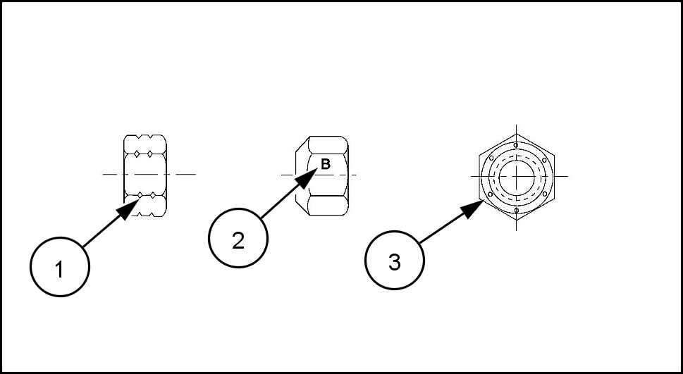
Inch Lock Nuts, All Metal (Three optional methods)
INTRODUCTION
20090268 4 Grade Identification Grade Corner Marking Method (1) Flats Marking Method (2) Clock Marking Method (3) Grade A Notches Mark Marks Grade B One Circumferential Notch Letter B Three Marks Grade C T Circumferential Notches Letter C Six Marks 48048556 16/09/2016
T orque - Standard torque data for hydraulics
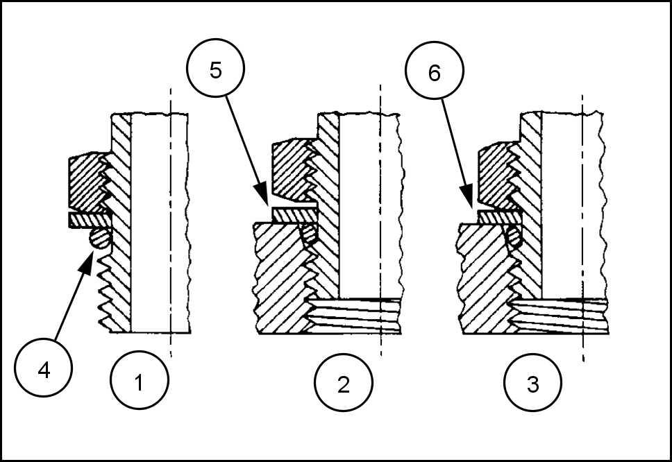
INST ALLA TION ADJUST ABLE FITTINGS STRAIGHT THREAD O RING BOSSES
Lubricate the O - ring coating with a light oil
Install the O - ring the groove adjacent the metal backup washer which assembled the extreme end the groove (4)
Install the fitting into the SAE straight thread boss until the metal backup washer contacts the face the boss (5)
NOTE: not over tighten and distort the metal backup washer
Position the fitting turning out (counterclockwise) a maximum one turn. Holding the pad the fitting with a tighten the locknut and washer against the face the boss (6)
ANDARD T ORQUE T A FOR HYDRAULIC TUBES AND FITTINGS
INTRODUCTION
ANZ - - - - - - - - - MEA
570ST
1
23085659
TUBE NUTS FOR 37° FLARED FITTINGS O - RING BOSS PLUGS ADJUST ABLE FITTING LOCKNUTS, SWIVEL JIC37° SEA SIZE TUBING THREAD SIZE T ORQUE T ORQUE 4 ( 1 / 4 ) 7 / - - N·m ( 9 - ) 8 - N·m ( 6 - ) 5 ( 5 / ) 1 / 2 - - N·m ( - ) - N·m ( - ) 6 9.5 ( 3 / 8 ) 9 / - - ( - ) - ( - ) 8 12.7 ( 1 / 2 ) 3 / 4 - - N·m ( - ) - N·m ( - ) ( 5 / 8 ) 7 / 8 - - N·m ( - ) - N·m ( - ) 19.1 ( 3 / 4 ) 1 - 1 / - 104 - 1 1 1 ( - ) - ( - ) 22.2 ( 7 / 8 ) 1 - 3 / - 122 - 136 ( - 100 ) - 109 ( - ) 25.4 ( 1 ) 1 - 5 / - 149 - 163 N·m ( 1 - 120 ) 108 - 122 N·m ( - ) ( 1 - 1 / 4 ) 1 - 5 / 8 - 190 - 204 N·m ( 140 - 150 ) 129 - 158 N·m ( - 1 ) 38.1 ( 1 - 1 / 2 ) 1 - 7 / 8 - 217 - 237 ( 160 - 175 ) 163 - 190 ( 120 - 140 ) 50.8 ( 2 ) 2 - 1 / 2 - 305 - 325 N·m ( 225 - 240 ) 339 - 407 N·m ( 250 - 300 ) These torques are not recommended for tubes ( 1 / 2 ) and larger with wall thickness ( 0.035 ) The torque specified for 0.889 ( 0.035 ) wall tubes each application individually Before installing and torquing ° flared clean the face the flare and threads with a clean solvent Loctite cleaner and apply hydraulic sealant L OCTITE ® 569 the ° flare and the Install fitting and torque specified torque, loosen fitting and retorque specifications. 48048556 16/09/2016
PIPE THREAD FITTING T ORQUE
Before installing and tightening pipe clean the threads with a clean solvent Loctite cleaner and apply sealant L OCTITE ® 567 PST P IPE S EALANT for all fittings including stainless steel L OCTITE ® 565 PST for most metal fittings. For high filtration / zero contamination tems use L OCTITE ® 545
INST ALLA TION ORFS - RING FLA T F ACED) FITTINGS
When installing ORFS fittings thoroughly clean both flat surfaces the fittings (1) and lubricate the O - ring (2) with light Make sure both surfaces are aligned properly T orque the fitting specified torque listed throughout the repair manual.

NOTICE: the fitting surfaces are not properly cleaned, the O - ring will not seal properly the fitting surfaces are not properly the fittings may damaged and will not seal properly
NOTICE: Always use genuine factory replacement oils and filters ensure proper lubrication and filtration gine and hydraulic system oils.
The use proper and keeping the hydraulic system clean will extend machine and component life.
INTRODUCTION
PIPE THREAD FITTING Thread Size T orque (Maximum) 1 / 8 - N·m ( ) 1 / 4 - N·m ( ) 3 / 8 - ( ) 1 / 2 - N·m ( ) 3 / 4 - N·m ( )
5001 1 183 2 48048556 16/09/2016
Abbreviation - Measurements
INTRODUCTION
570ST ANZ - - - - - - - - - MEA T ypical applications Metric unit Imperial unit Name Symbol Name Symbol Area (Land area) hectare acre square foot ft² square meter square inch in² square millimeter mm² square inch in² Electricity ampere A ampere A volt V volt V microfarad microfarad ohm Ω ohm Ω Force kilonewton pound newton N pound Force per length newton per meter N / m pound per foot / pound per inch / Frequency megahertz MHz megahertz MHz kilohertz kHz kilohertz kHz hertz hertz Frequency Rotational r / min r / min ª revolution per minute rpm revolution per minute rpm Length kilometer mile meter m foot centimeter inch millimeter inch micrometer Mass kilogram pound gram g ounce milligram Power kilowatt horsepower watt W Btu per hour Btu / Btu per minute Btu / min Pressure stress (Force per area) kilopascal kPa pound per square inch psi inch mercury inHg pascal inch water inH2O megapascal MPa pound per square inch psi 48048556 16/09/2016
INTRODUCTION T ypical applications Metric unit Imperial unit Name Symbol Name Symbol T emperature (other than Thermodynamic) degrees Celsius degrees Fahrenheit T ime hour h hour h minute min minute min second s second s T orque (includes Bending moment, Moment force, and Moment a couple) newton meter N m pound foot pound foot V elocity kilometer per hour / h mile per hour mph meter per second m / s foot per second / s millimeter per second / s inch per second / s meter per minute m / min foot per minute / min V olume (includes Capacity) cubic meter cubic yard yd³ liter l cubic inch in³ liter l gallon gal gallon gal quart quart milliliter fluid ounce V olume per time (includes Discharge and Flow rate) cubic meter per minute / min cubic foot per minute ft³ / min liter per minute l / min gallon per minute gal / min milliliter per minute / min gallon per minute gal / min Sound power level and Sound pressure level decibel decibel 48048556 16/09/2016
Capacities
INTRODUCTION
570ST ANZ - - - - - - - - - MEA Usage Specification Brand Capacity 1 T ransmission oil 2WD ( Akcela NEXPLORE (MUL16.00 l ( 4.23 gal ) 2 T ransmission oil 4WD ( Akcela NEXPLORE (MUL18.50 l ( 4.89 gal ) 3 Hydraulic Oil ( Akcela NEXPLORE (MUL125.00 L ( 33.02 gal ) 4 Rear axle oil SAE 20W40 Akcela transaxle fluid 20W40 l ( gal ) 5 4WD front axle oil ( Akcela NEXPLORE (MUL8.90 L ( 2.35 gal ) 6 Engine oil - III API CI4 , SAE 15W - Akcela 1 (API9.10 L ( 2.40 gal ) 7 Brake fluid ISO 7308 Akcela LHM Fluid 0.67 l ( 0.18 gal ) 8 Engine Coolant Premix Grade EG4 Akcela premium antifreeze LDR - 25C l ( 5.28 gal ) 9 Front Axle (2ED) Akcela Moly Grease Moly disulfide Moly disulfide ( ) V arious joints Akcela multi - purpose grease GREASE GRADE 2 (IS:7623) GREASE, EP2 ( ) 1 1 Refrigerant R - 134a ( ( ) P AG OIL (Compressor) - ( 270 - 300 ( 9) 48048556 16/09/2016
Engine 570ST 48048556 16/09/2016
SER VICE MANUAL
Contents Engine[10.001] Engine and crankcase . . . . . . . . . . . . . . . . . . . . . . . . . . . . . . . . . . . . . . . . . . . . . . . . . . . . . . . . . . . . . . . 10.1 [10.254] Intake and exhaust manifolds and muf fler . . . . . . . . . . . . . . . . . . . . . . . . . . . . . . . . . . . . . . . . . . . 10.2 Engine cooling system 48048556 16/09/2016
EngineEngine and crankcase - 001 570ST 48048556 16/09/2016 10.1 [10.001] / 1
Contents EngineEngine and crankcase - 001 SER VICE Engine Remove 3 Install 6 DIAGNOSTIC Engine T roubleshooting 9 48048556 16/09/2016 10.1 [10.001] / 2
Engine - Engine and crankcase
Engine - Remove
Prior operation:
Refer Basic instructions
Prior operation:
Refer Hood - Remove
Prior operation:
Refer Radiator - Remove
Prior operation:
Refer Intake and exhaust manifolds and muffler - Remove (10.254)
NOTE: Put identification tags all disconnected hoses and Close all disconnected hoses and fittings with caps and plugs immediately
NOTE: The images this procedure may different from your machine and are for reference only
A TTENTION: Allow the engine reach normal ture before performing any service maintenance
W ear safety gloves and goggles for protection from hot components and fluids severe burns could
Drain engine oil loosening the drain Collect the oil a clean container , cap and keep aside a clean place.
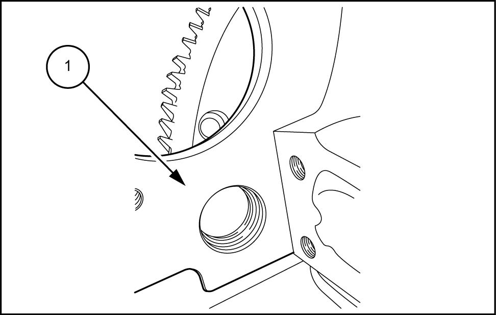
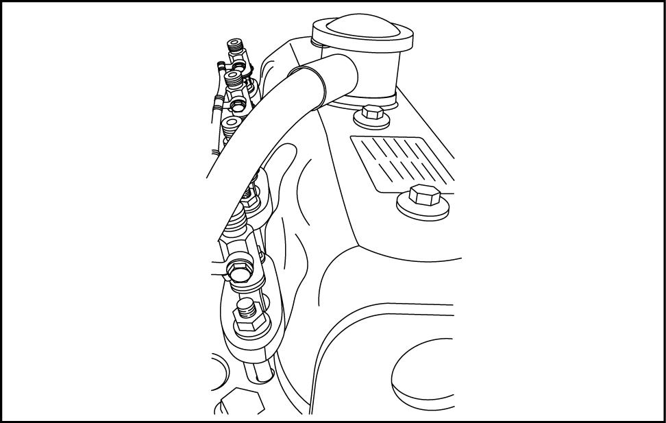
Disconnect the fuel return and inlet lines (1) from the mud filter (4) and cap them immediately
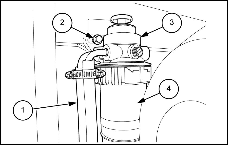
Loosen the mounting bolts (2) and remove the bly (3) from the machine.
Remove the exhaust pipe (1) the turbocharger and cap
PTIL13TLB0953AB 1
PTIL13TLB0956AB 2 48048556 16/09/2016 10.1 [10.001] / 3
Engine - Engine and crankcase
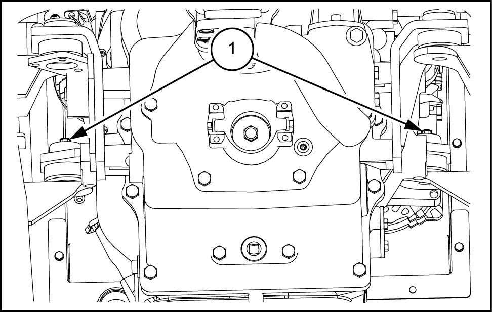
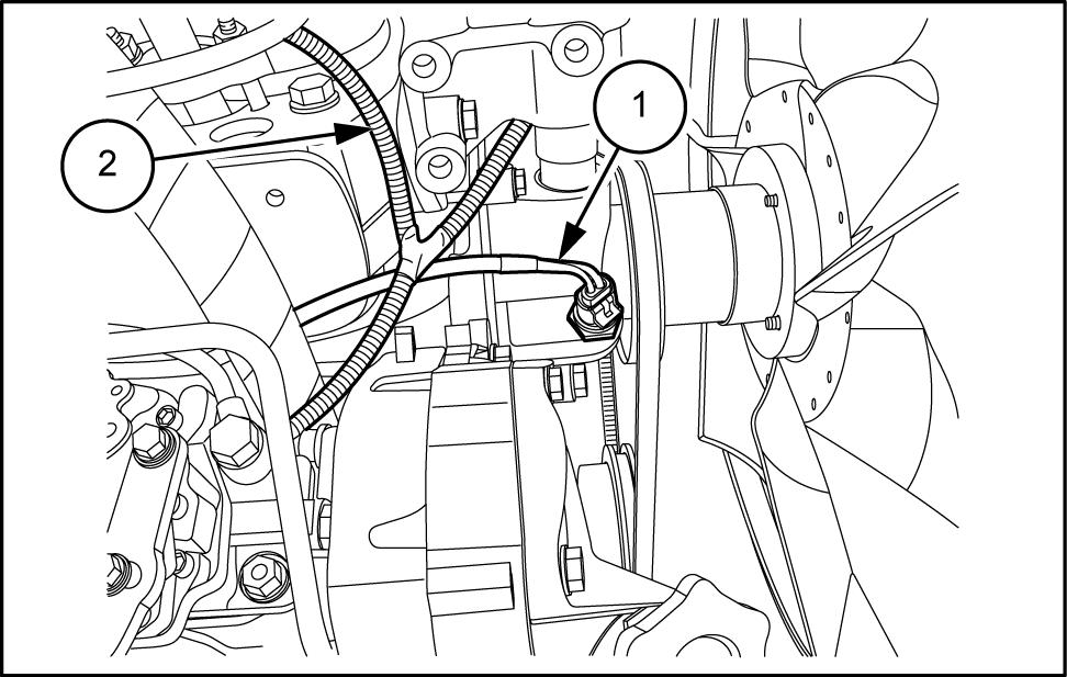
Connect the coolant temperature (1) , alternator , oil pressure (2)
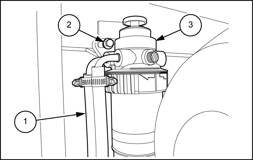
Connect the fuel return and inlet lines (1) and mount the fuel filter assembly (3) tightening the mounting bolts (2)
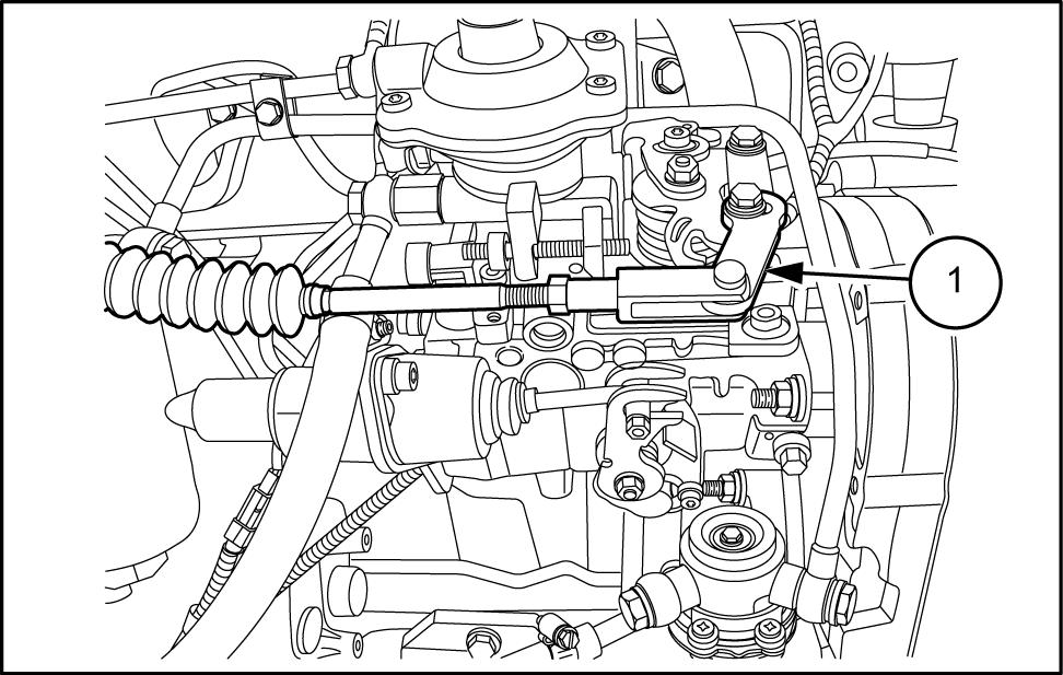
Connect the throttle rod (1)
10. Connect the throttle cable from the mounting bracket.
1 Connect the electrical connector for the oil pressure
Install the exhaust pipe (1) the turbocharger the muf fler
PTIL13TLB0955AB 4
PTIL13TLB0953AB 5
PTIL13TLB0954AB 6
T ighten a torque value 6.57.5 N·m ( 4.85.5 ) . PTIL13TLB0956AB 7 48048556 16/09/2016 10.1 [10.001] / 7
Engine - Engine and crankcase
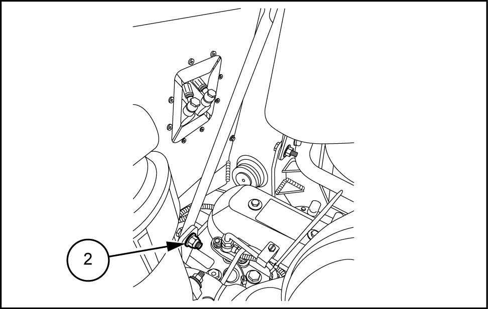
13. Attach the muf fler and brackets (1) the engine.
T ighten a torque value - N·m () . PTIL13TLB0958AB
14. Install the muf fler support bracket bolt (2) .
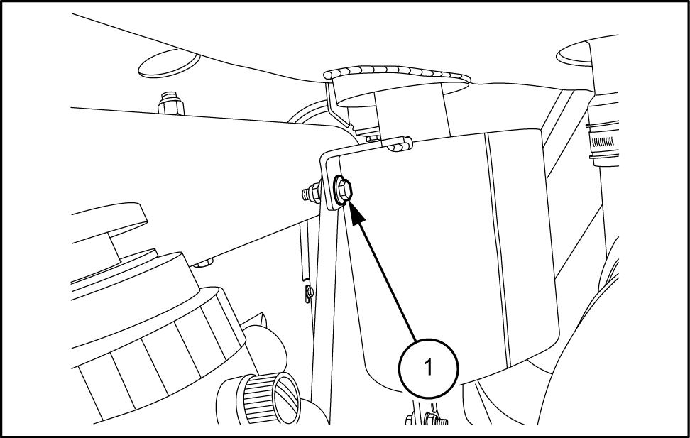
T ighten a torque value - N·m () PTIL13TLB0957AB
15. Attach the aspiration hose and the crank case lation
Install the exhaust Refer Intake and exhaust manifolds and muffler - Install (10.254)
17. Install the cooling pack. Refer Radiator - Install
Fill the engine oil and cooling system the scribed
19. See capacities Capacities for specifications.
20. Install air cleaner assembly .
Install the Refer Hood - Install
Connect the battery Refer Basic instructions
Start the engine and keep
PTIL13TLB1467AB
8
9
Unlock the support strut lock and lower the loader 48048556 16/09/2016 10.1 [10.001] / 8
Engine - Engine and crankcase
Engine - T roubleshooting
NOTE: The following table lists problems and their possible causes with recommended remedial
A TTENTION: When attending a repair the cause the problem must also investigated and corrected avoid repeat
Problem
Engine does not develop full power
Possible Cause Correction
Clogged air cleaner
Clean renew element
Fuel line obstructed Clean
Faulty injectors
Clean and reset
Incorrect valve clearance adjustment Clean and reset worn sticking valves
Blown head gasket
Incorrect fuel delivery
Low cylinder compression
Oil pressure warning light fails operate Bulb burnt out
Replace valves with new and / machine the valve guide bores
Check head flatness and fit new gasket
Check injectors and pump
Renew piston rings - bore / - sleeve necessary
Renew bulb
W arning Light pressure switch faulty Renew pressure switch
W arning light circuit faulty
Excessive exhaust smoke Exhaust leak exhaust manifold
Check and renew wiring
Fit new gasket
Air cleaner dirty restricted Clean
Excessive fuel delivery
Engine knocks Diluted thin oil
Overall injection pump and injectors
Check crankshaft bearings for change
Drain and refill with specified oil and renew filter Ascertain cause dilution
Insuf ficient oil supply
Check oil level and top necessary
Overhaul renew pump necessary
Check oil filter not clogged
Low oil pressure Overhaul pump relief valve necessary
Excessive crankshaft end play
Excessive connecting rod main
Bent twisted connecting rods
Replace thrust washer
Install new bearing inserts and / bearing clearance - grind crankshaft
Renew connecting rods
Crankshaft journals out round - grind crankshaft and fit undersize ing inserts
Excessive piston cylinder - bore / - sleeve block and fit i bore ance new pistons
Excessive piston ring clearance
Broken rings
Excessive piston pin clearance
Fit new pistons and rings
Fit new rings, check bore and pistons for damage
Fit new piston pin
Piston pin retainer loose missing Install new retainer , and check bore / pistons for damage
Excessive camshaft play
Imperfections timing gear teeth
Excessive timing gear backlash
Install new thrust plate
Renew timing gear
Check and adjust backlash / renew , timing gear
Engine overheats
Coolant hose connection leaking lapsed
Radiator cap defective not sealing
Radiator leakage
T ighten hose renew hose damaged
Renew radiator cap
Repair / renew radiator
Improper fan belt adjustment - adjust fan belt
Radiator fins restricted
Faulty thermostat
Internal engine leakage
W ater pump faulty
Clean with compressed air
Renew thermostat
Check for source leakage. Renew ket defective parts
Overhaul water pump
10.1 [10.001] / 9
48048556 16/09/2016