carly hannestad
fly space
BUILDING ARTS STUDIO I • TAUGHT BY:
FEDERICO GARCIALAMMERS
• SOUTH DAKOTA STATE UNIVERSITY • FALL 2017
This studio explored how “the stair” represents space and how a system of stairs characterizes a spatial progression. A cube provided the ideal site for creating sequences that helped define space, and the materials we used (foam, wood, and museum board) helped to detail the relationships between solid and void. This project investigated the sequential variety that can be created using a finite amount of space coupled with unique constraints.
This project was meant to be an iterative process. It was important to make things more than once, twice, or even three times. This project depended on extensive iteration. Goals and outcomes included using solid/void material conditions to define space, identifying the space of the stairs, developing spatial progression through systems of stairs, understanding assembly of materials and the difference between mass and plane, discussing the purpose of the stair, and constructing full scale models of the stair to eventually be drawn in section.
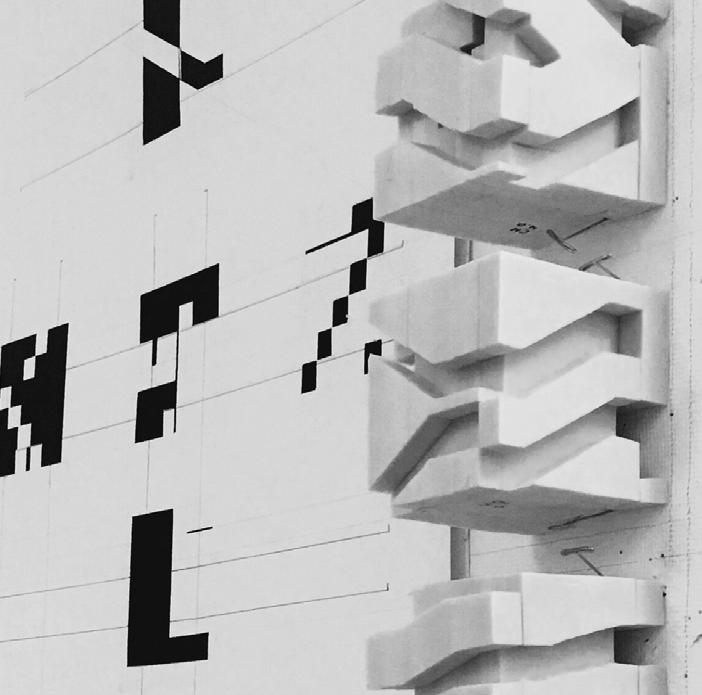
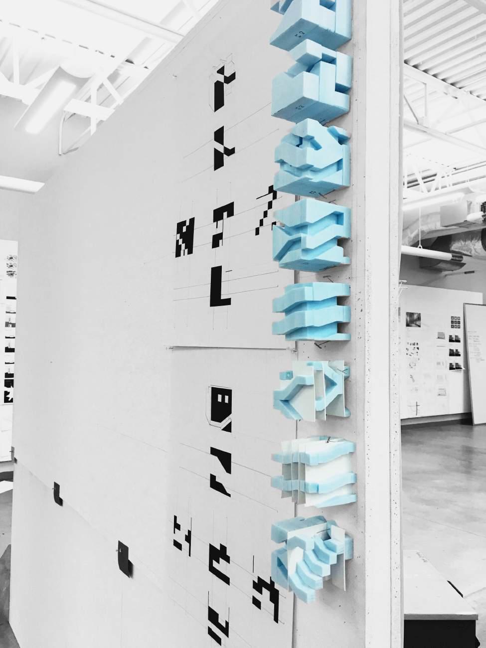
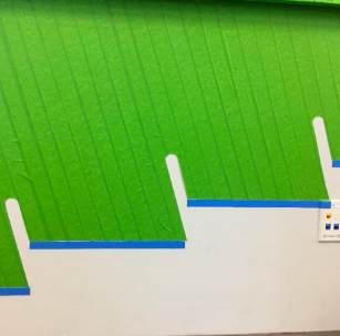
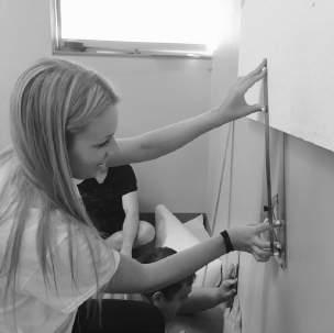
To introduce the subject of ‘the stair,’ each student was assigned a well known or recognizable stair to reproduce at a 1:1 scale. These reproductions were tape drawings projected on a portion of a wall within the architecture studio. The measurements of the stair section were translated to the wall with blue tape being a section cut and green tape being the elevation beyond (see images on next spread). The next phase of the studio involved the iterative cube process. The first three foam cubes were sized 3” x 3” x 3” to demonstrate spatial sequences and had to be sliced into three pieces, carved out, and then put back together. The next three foam cubes had to be sliced into six pieces with the requirement that the stairs had to connect and progress from the bottom to the top. The next three cubes were designed to be the inverse of the previous three cubes. Three cubes were then selected out of the nine to be modeled at 6” x 6” x 6” scale using MDF and museum board. Finally, the cubes were drawn in section, revealing mass and void.
A cube provided the ideal site for creating sequences that helped define space.
SECTION DRAWINGS These drawings reveal mass and void within the cubes. The cuts were made and black paper was placed behind each void to emphasize the cuts.
TAPE DRAWING Initial 1:1 tape drawing to study the section of an existing stair. My assigned stair was the Juilliard Stairs at the Juilliard School in NYC (Diller Scofidio + Renfro). Image courtesy of Federico Garcia Lammers.


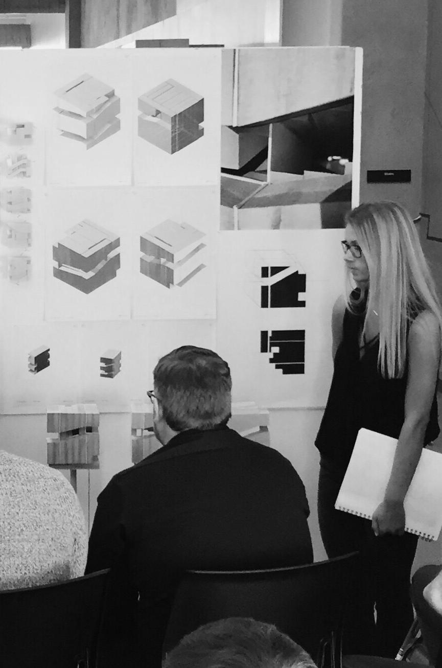
FINAL CUBE PIN-UP The final three MDF cubes, corresponding section drawings, and perspective photos. Left image courtesy of Federico Garcia Lammers.
it was important to make things more than once, twice, or even three times. This project depended on extensive iteration.
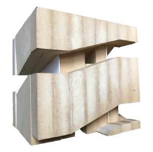
6” X 6” X 6” One of the three MDF study cubes.
age-inplace cabin
INTERIOR DESIGN STUDIO II • TAUGHT BY: DALLAS WILLMAN • SOUTH DAKOTA STATE UNIVERSITY • SPRING 2019
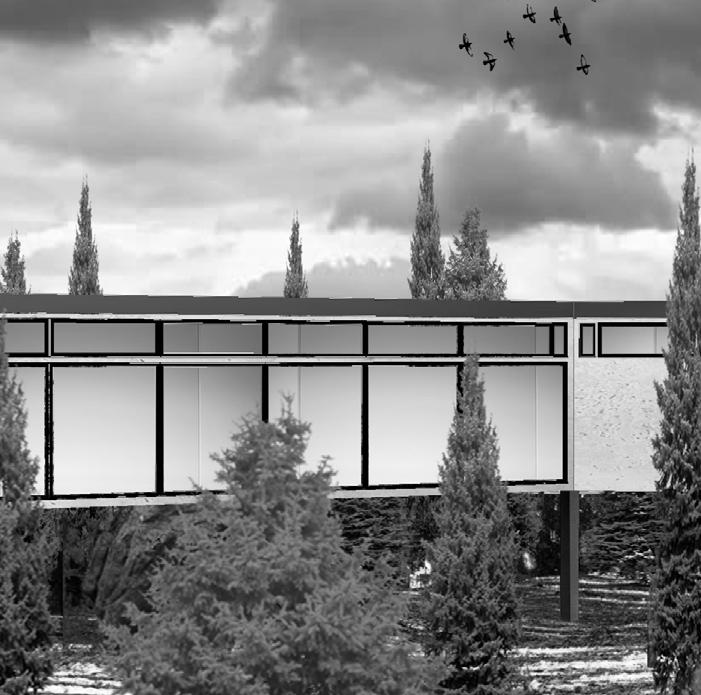
The goal of this project was to design a home for a retired artist, taking into account his age, lifestyle, and design preferences. The site given was in Priest Lake, ID. The artist’s work was used to inspire the design of the lake home. The client frequently used heavy metals like copper and Cor-Ten steel for his installations, often resulting in sharp edges. The artist also wanted space to entertain and host his family. This inspired the idea of a lightning bolt as a basis for the design. The home resembles a lightning bolt, becoming more private as it extends towards the lake. The public spaces such as the living room are towards the front, and bedrooms are towards the back of the house and face the lake.
The focus of this home was to make it comfortable and accessible to an aging individual. The fictional client wanted a home that he and his wife could age-in-place in without having to modify in the future. A wheelchair’s turning radius was considered and smooth surfaces were used for the floors. There was also an emphasis on bringing the outdoors into the home. The home is positioned right within the trees and features an interior zen garden that separates interior spaces.
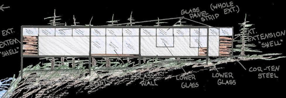
INITIAL EXTERIOR SKETCH
The home resembles a lightning bolt, becoming more private as it extends towards the lake.
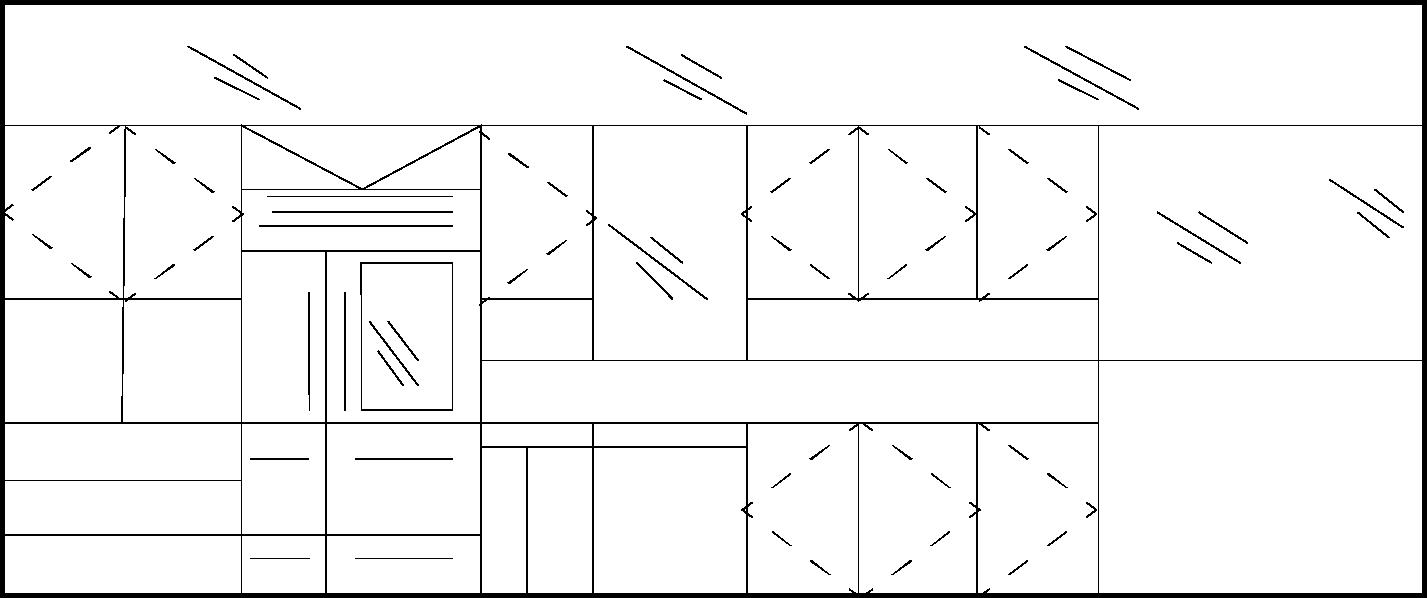
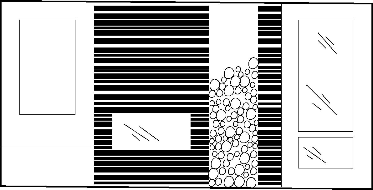
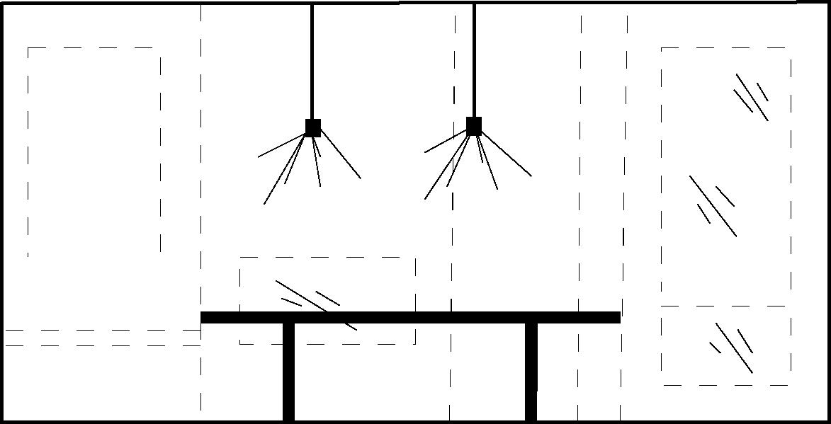
ELEVATION SKETCHES Views of the kitchen and both walls of the dining area.
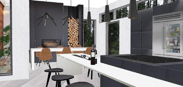
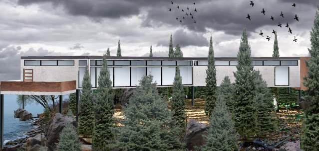
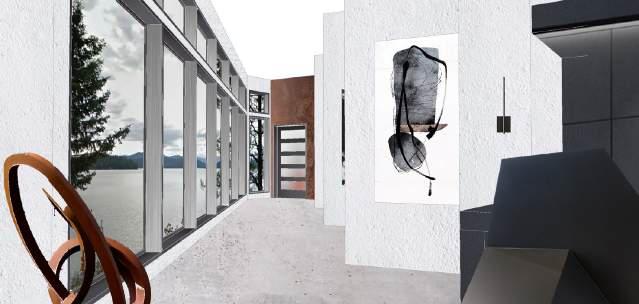
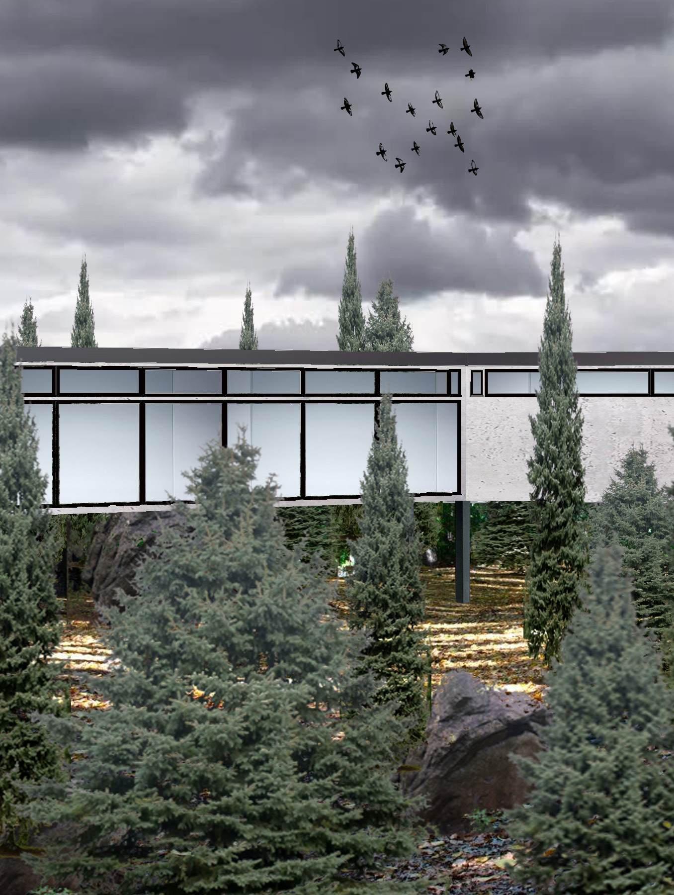
PERSPECTIVE COLLAGES
Views of the exterior, kitchen and dining area, and hallway. The interior of the home features a zen garden for quiet introspection. The kitchen is also designed to be accessible to someone in a wheelchair.
The goal of this project was to design a home for a retired artist, taking into account his age, lifestyle, and design preferences.
technical drawing
INTRODUCTION TO ARCHITECTURAL DRAWING • TAUGHT BY:
CHRISTINA
STARK, AIA • UNIVERSITY OF MINNESOTA • FALL 2019
DESIGN DRAWING • TAUGHT BY:
ARTHUR CHEN, Ph.D. • UNIVERSITY OF MINNESOTA • SPRING 2021
These courses focused on architectural visualization through the practice of drawing. The process of these drawings focused attention on different aspects of architecture. Drawing is a crucial form of communication that relays important architectural information through visual portrayals. Architectural drawing also shows design intent and constructibility. A sequence of corresponding exercises were done during both courses in order to demonstrate this concept. Each exercise showed a different way of perceiving spaces and objects, while also exploring architectural concepts and progression of drawing ability.
These exercises involved freehand sketching and hard-line drafting with a combination of drawing mediums. The first drawing sequence began with freehand sketching of architectural spaces, then moved to technical drawing. The technical drawing exercises explored the purpose of elevations,
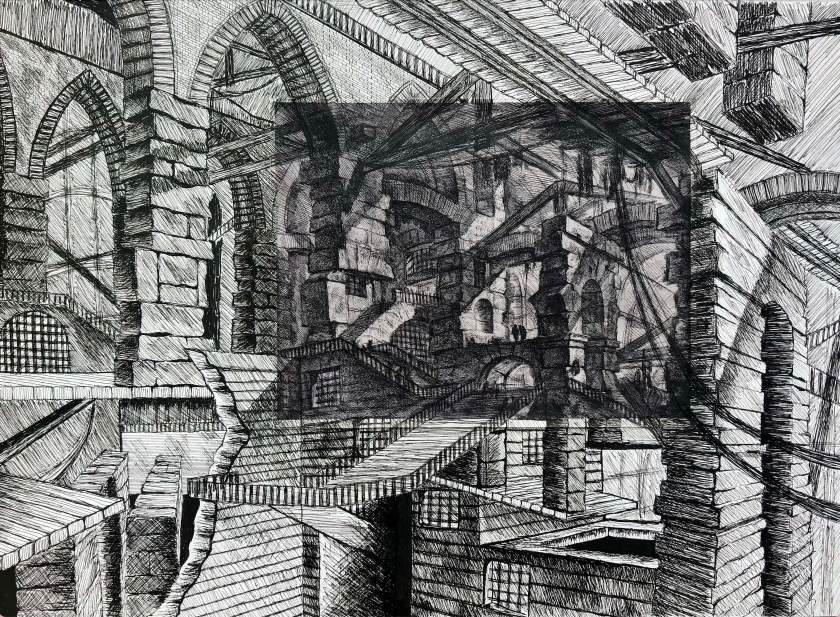
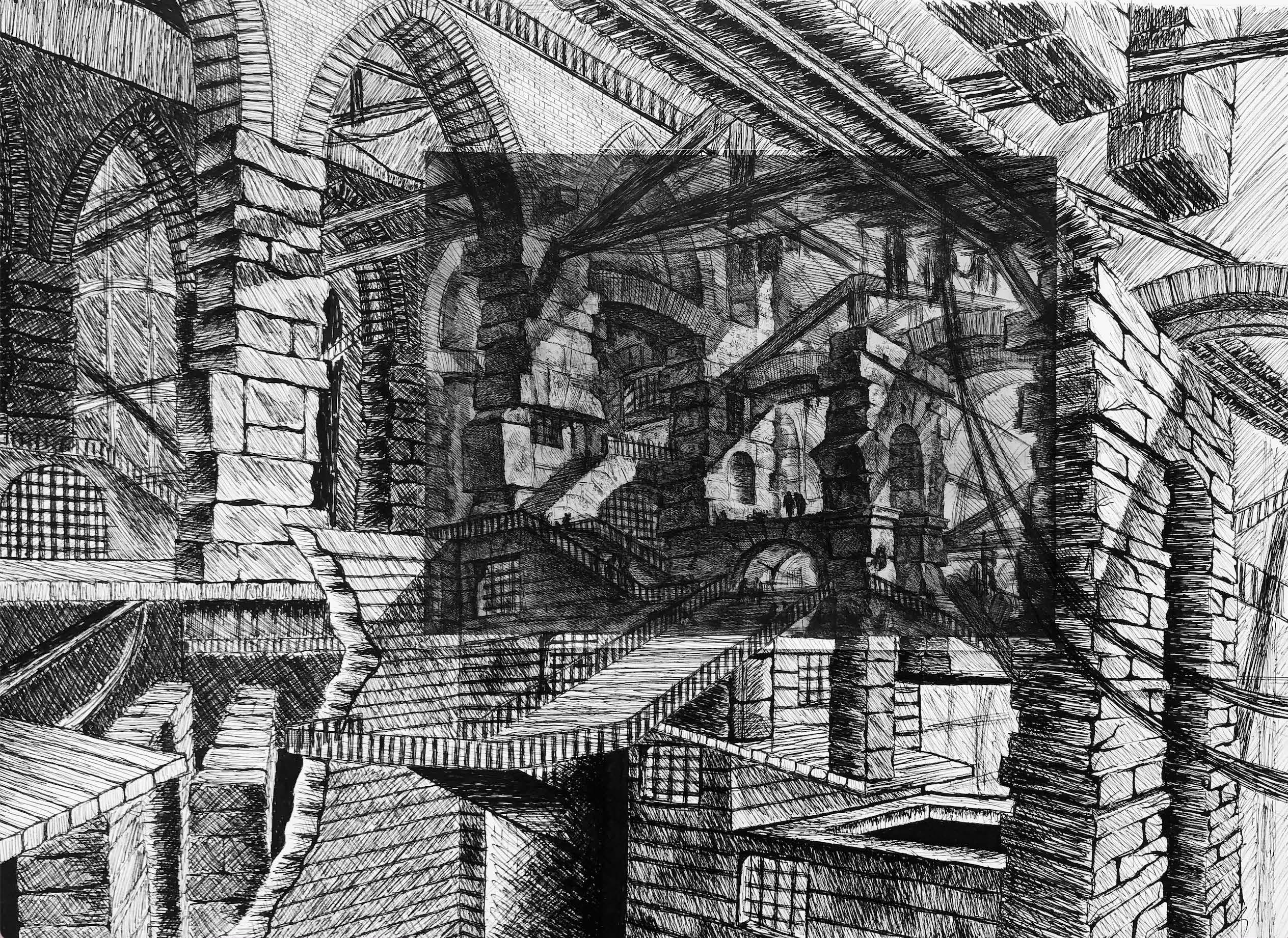
sections, and plan drawings. Precise measurements of objects were taken to be translated into scaled drawings. These drawings were executed through one and two-point perspective, axonometric projection, and isometric projection. Next, chalk drawing on black paper was an additive process that emphasized the layering of value to show depth and lighting changes. Finally, the Piranesi Prison was discussed. An existing etch was chosen and then continued through my own imagination.
HALL (UMN) VALUE DRAWING White chalk on black paper.
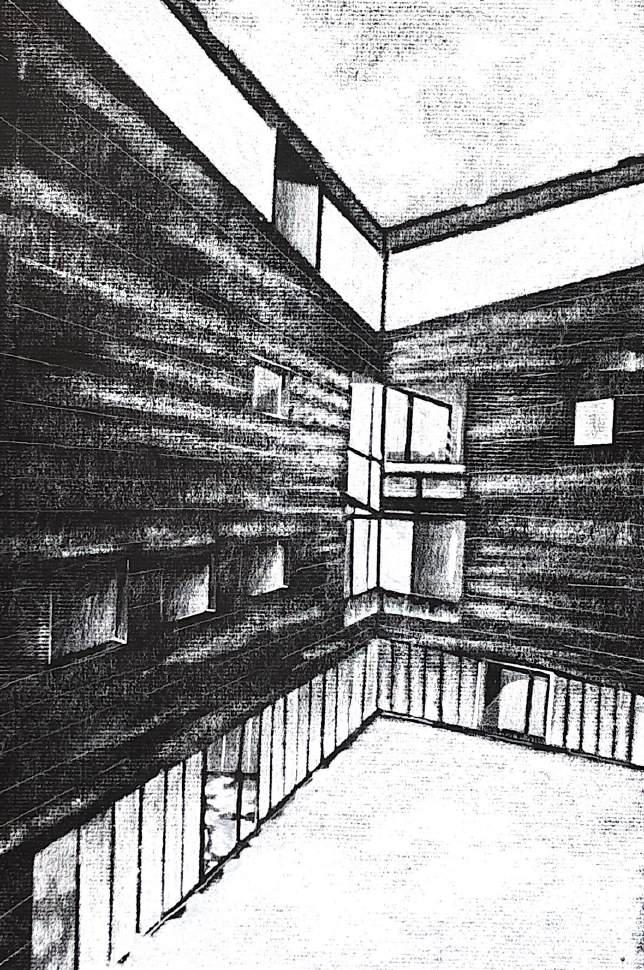
WILLIAMSON
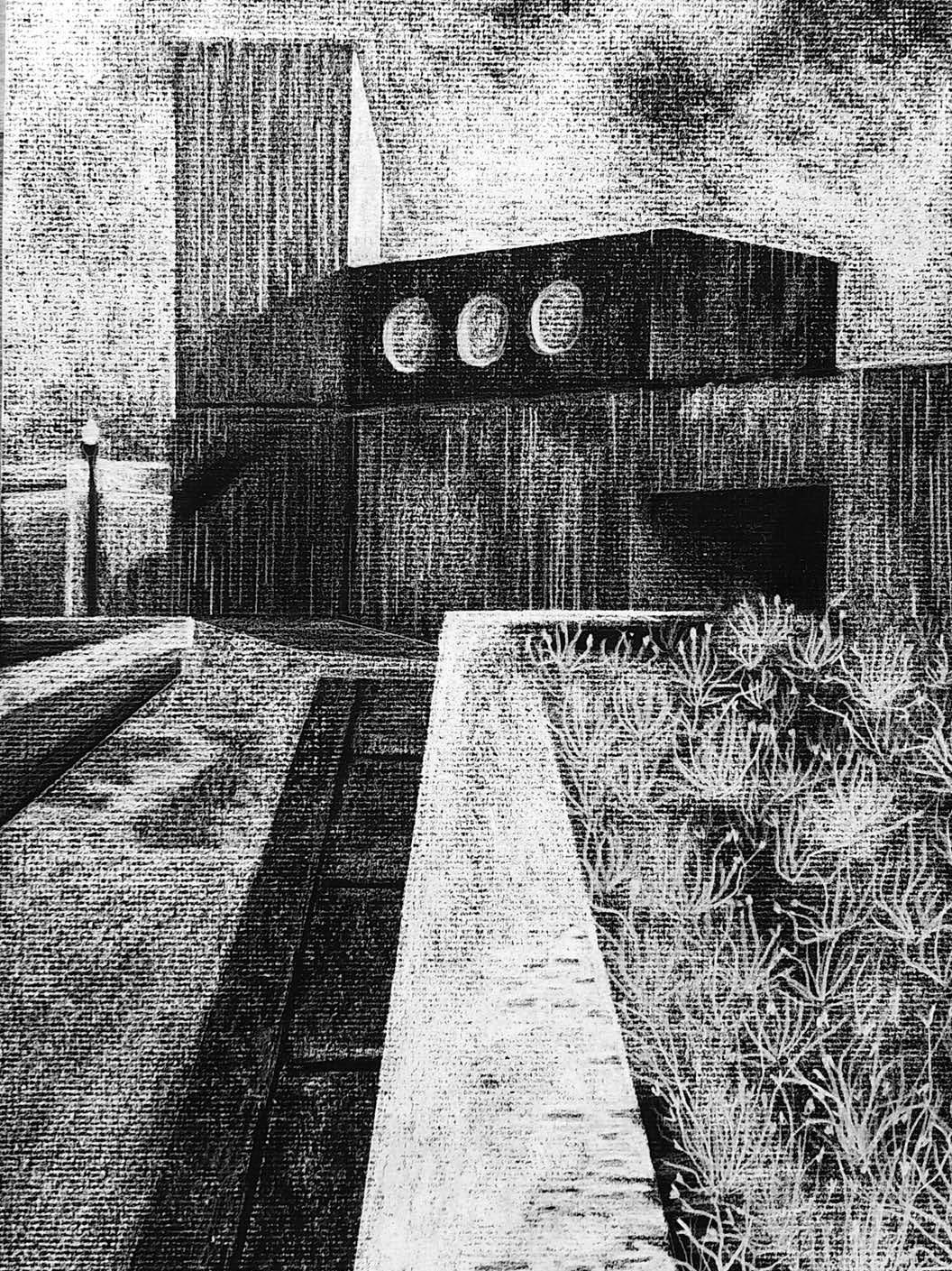
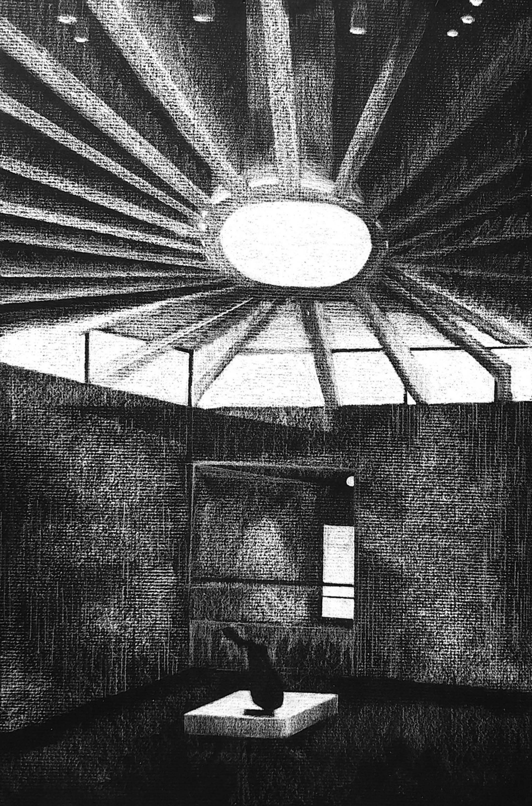
BRUNNIER
ART
MUSEUM
(IOWA STATE UNIVERSITY)
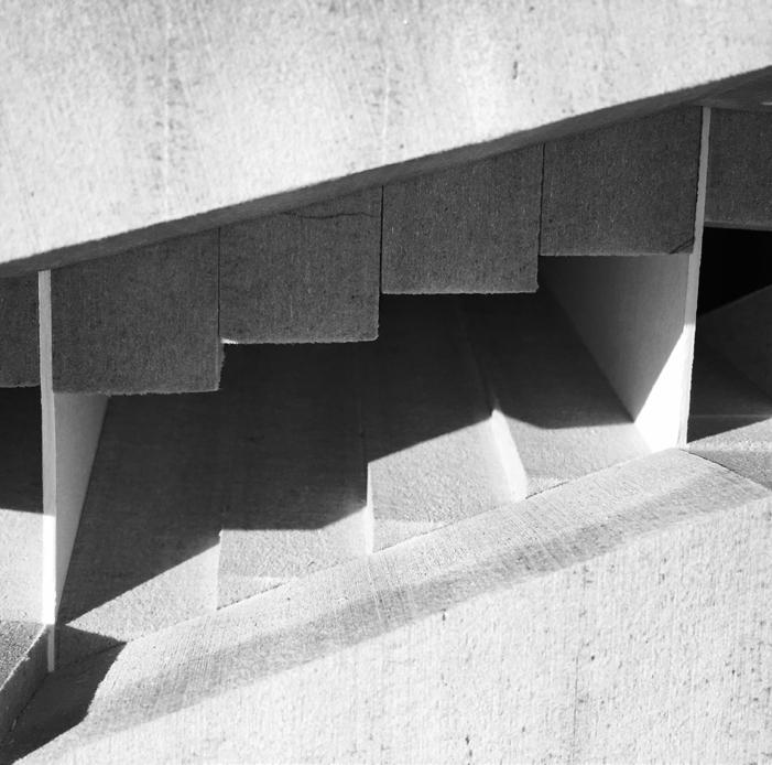
VALUE DRAWING White chalk on black paper. This drawing was meant to demonstrate how light enters from the windows, is projected onto the textured concrete walls, and reflected on the polished floor.
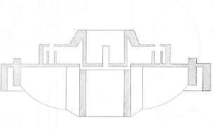
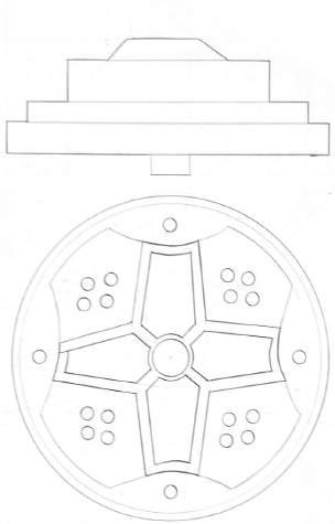
‘OBJECT X’ Section, elevation, and plan drawing of a randomly selected object.
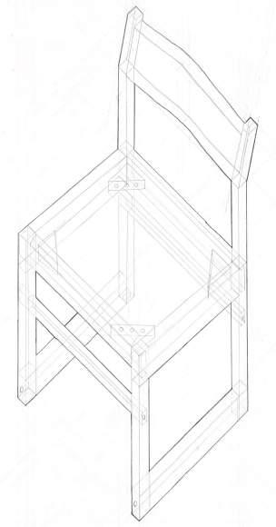
MEASURED
DRAWING A classroom chair was drawn in axon using a mixture of actual measurements and educated guesses about the pieces inside. (18’ x 22” paper)
RAPSON HALL (UMN) VALUE
DRAWING White chalk on black paper. This drawing was meant to demonstrate the brightness of a sunny day when there’s snow on the ground, and how that light reflects on the building.
chalk drawing on black paper was an additive process that emphasized the layering of value to show changes in depth and lighting.
from the ground up
GRAD. DESIGN STUDIO III (HYPOTHESIS 2080: A COMMUNITY OF THE FUTURE) • TAUGHT
BY: DAVID FRANCO, Ph.D, ANDREEA MIHILACHE, Ph.D, AND BRANDON PASS • CARTER BERTRAM (STUDIO PARTNER) • CLEMSON UNIVERSITY • FALL 2023
For this studio, my partner and I designed a housing community in Pawnee, Oklahoma set in the year 2080. We chose between six sites positioned to be profoundly impacted by climate change. Pawnee’s projected challenges include high heat and sun exposure, small earthquakes from nearby oil fracking, and continued extreme weather/tornadic activity.
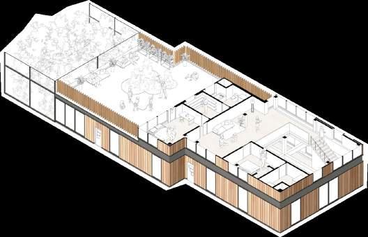
After researching the existing community, we discovered that there was a large percentage of the population that had served in the military. This prevalence of military service is what inspired us to design housing for veterans and their families. With 25% of the Native American population living in poverty in the US, we believed they would be particularly vulnerable to the increasing climate challenges of 2080. The housing community is comprised of four types of housing units that make up a larger network of housing pods. These residences are suitable for a variety of family sizes and makeups: single, disabled veteran
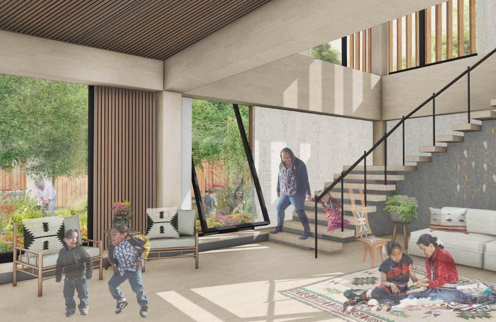
veteran (ADA), disabled veteran living with family (ADA), veteran with PTSD living with family, and a family with a deployed spouse. The non-ADA floor plans are two-stories and each plan has access to the pod’s greenhouse. Since many veterans suffer from symptoms of PTSD, special design considerations were incorporated into the units (see next spread). The units provide ample natural lighting, access to nature, open spaces for family gathering, and can be connected to encourage neighbor interaction.
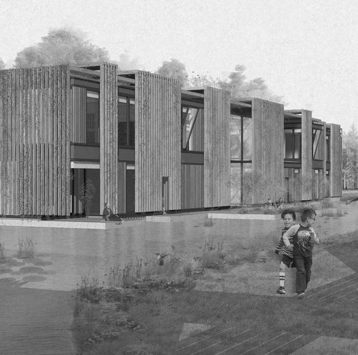
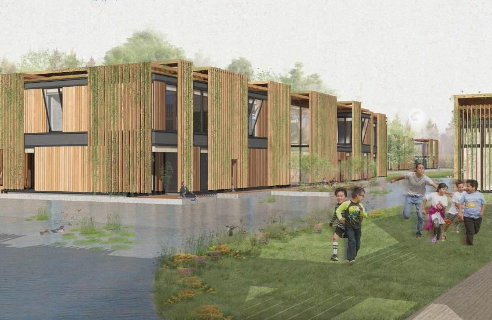
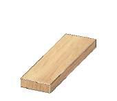
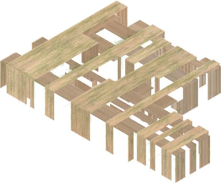
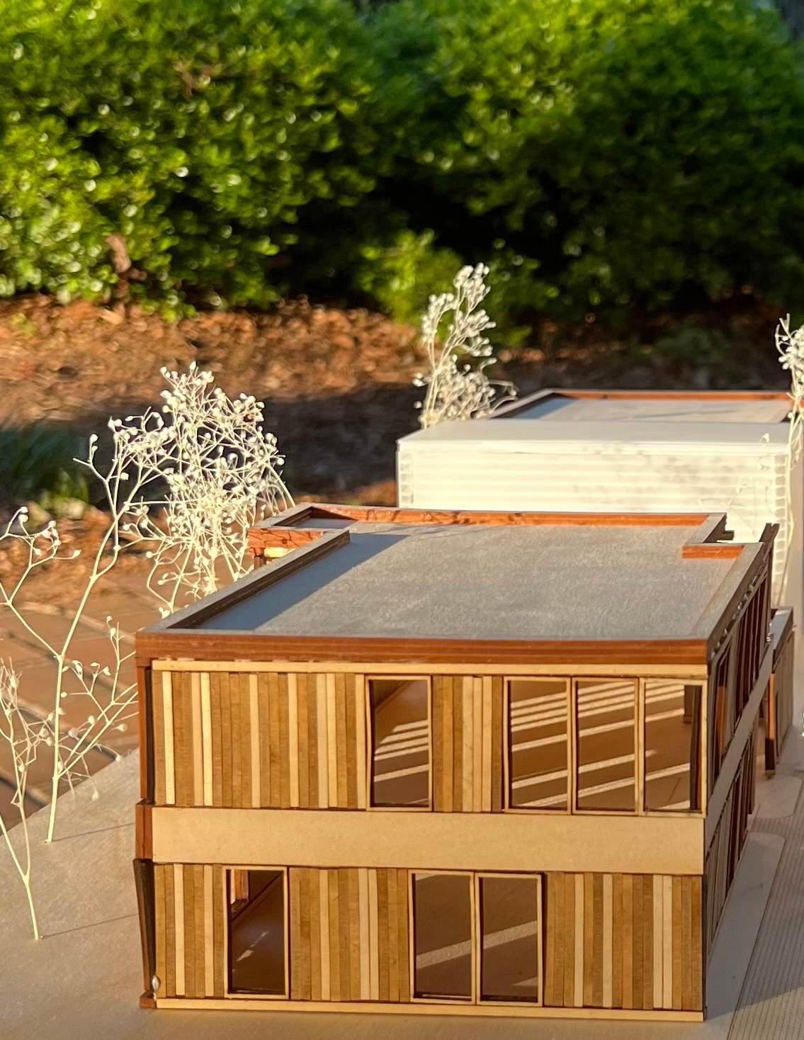
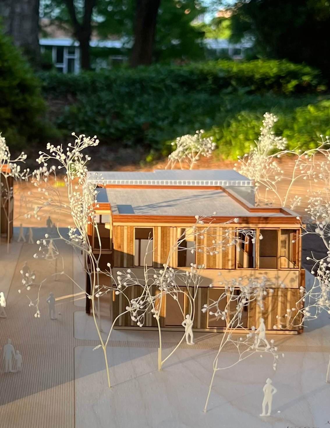
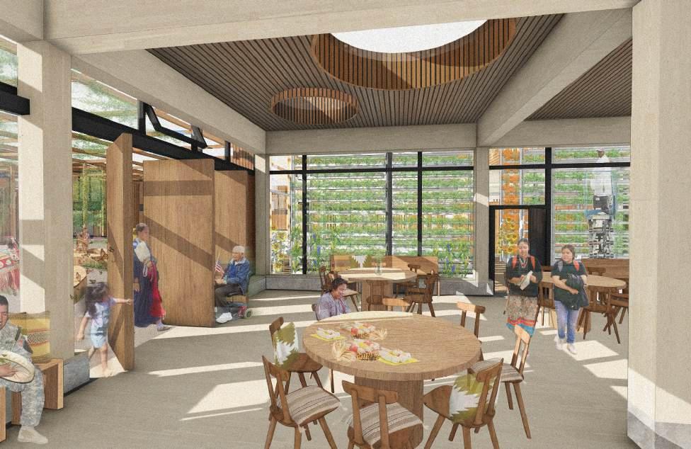
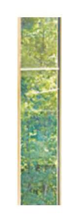
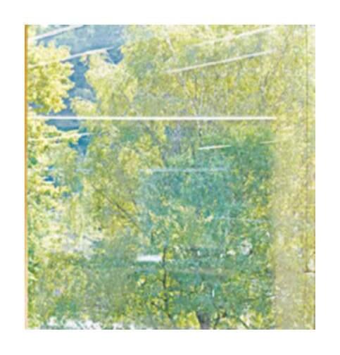
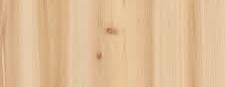
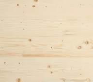
It was important to our design strategy to incorporate nature wherever possible and utilize local materials that have cultural significance. Our housing units utilize a mass timber structure and feature Western Red Cedar as the primary facade material. Cedar is considered to be a symbol of prayer and peace to the Pawnee. Since high heat is predicted for 2080, we designed a vertical farm in the central area of the site. We intentionally
chose crops that are culturally significant to the Pawnee, thus strengthening cultural traditions involved with planting, growing, and harvesting- as well as being environmentally compatible with the climate of Oklahoma. The climate challenges of 2080 will put the cultural connections of the Pawnee community in jeopardy and make it more important than ever to have housing that not only provides safety and shelter from the heat, but a therapeutic place for to veterans to heal.
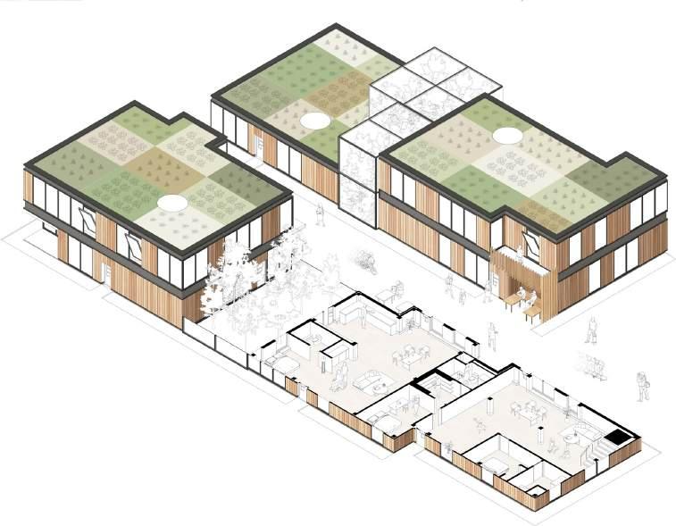
NATURE ACCESS
Breezeways between units provide shaded outdoor environments where residents can socialize and reap the physical and emotional benefits of nature access. Each pod also has two to three greenhouses which are accessed through the residences.
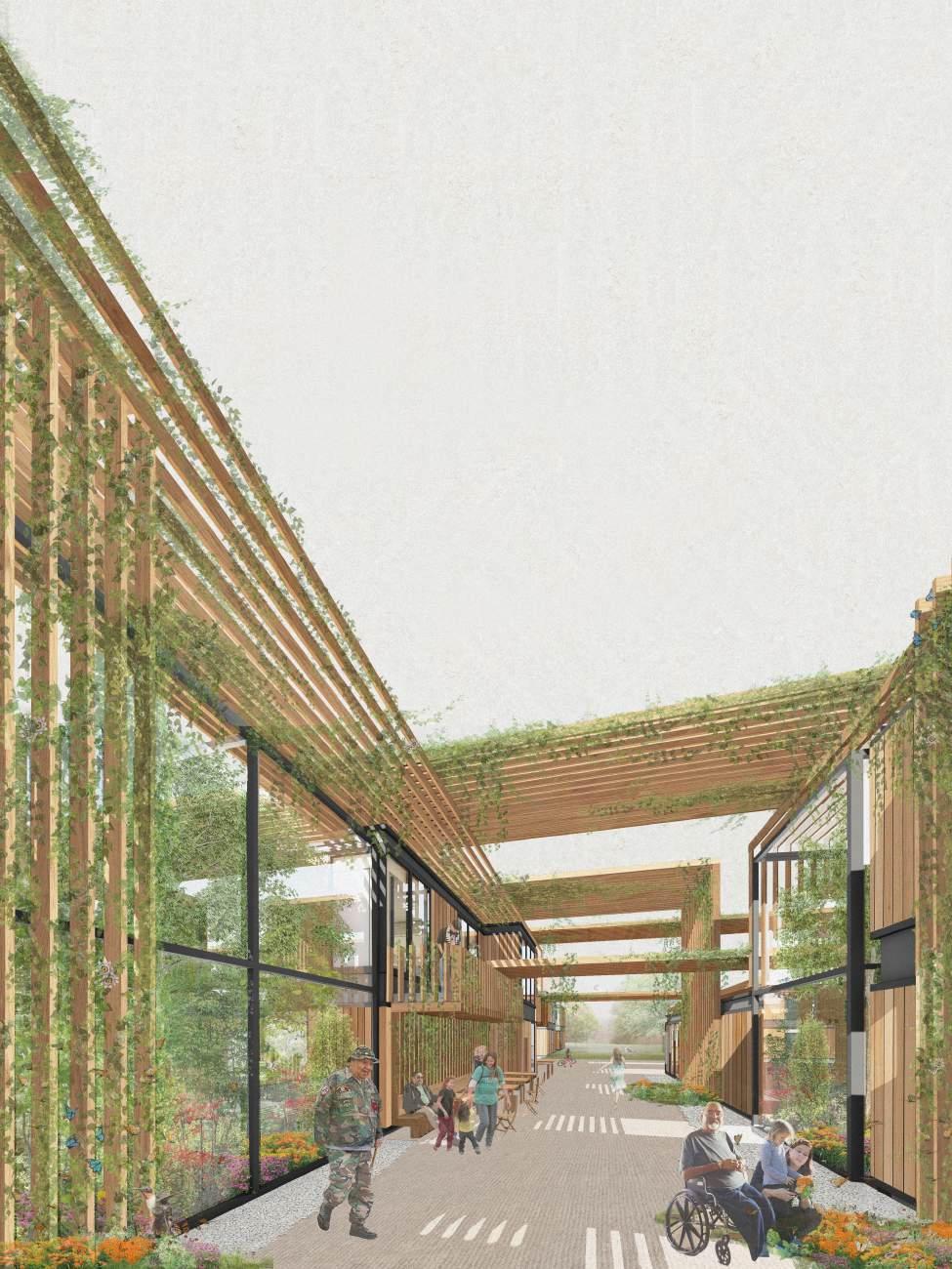
It was important to incorporate nature wherever possible and utilize local materials that have cultural significance.
GATHER Black Bear Creek’s excess rainwater enters into the site which creates an evaporative cooling effect and a space for residents to enjoy nature.
RESIDENTIAL POD (RIGHT)
With PTSD common among veterans, special design considerations were made to appease symptoms including: high ceilings, multiple exits (and views of them), acoustical control, natural light, and connections to nature. This was done while ensuring safety from the 2080 heat through the use of the trellis shading system.
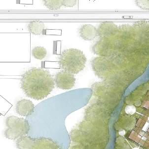
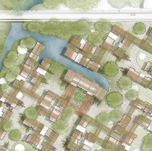
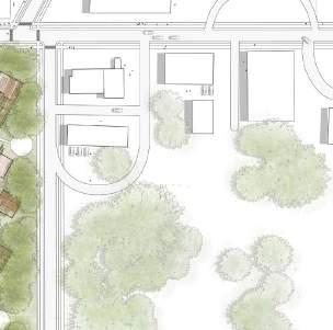
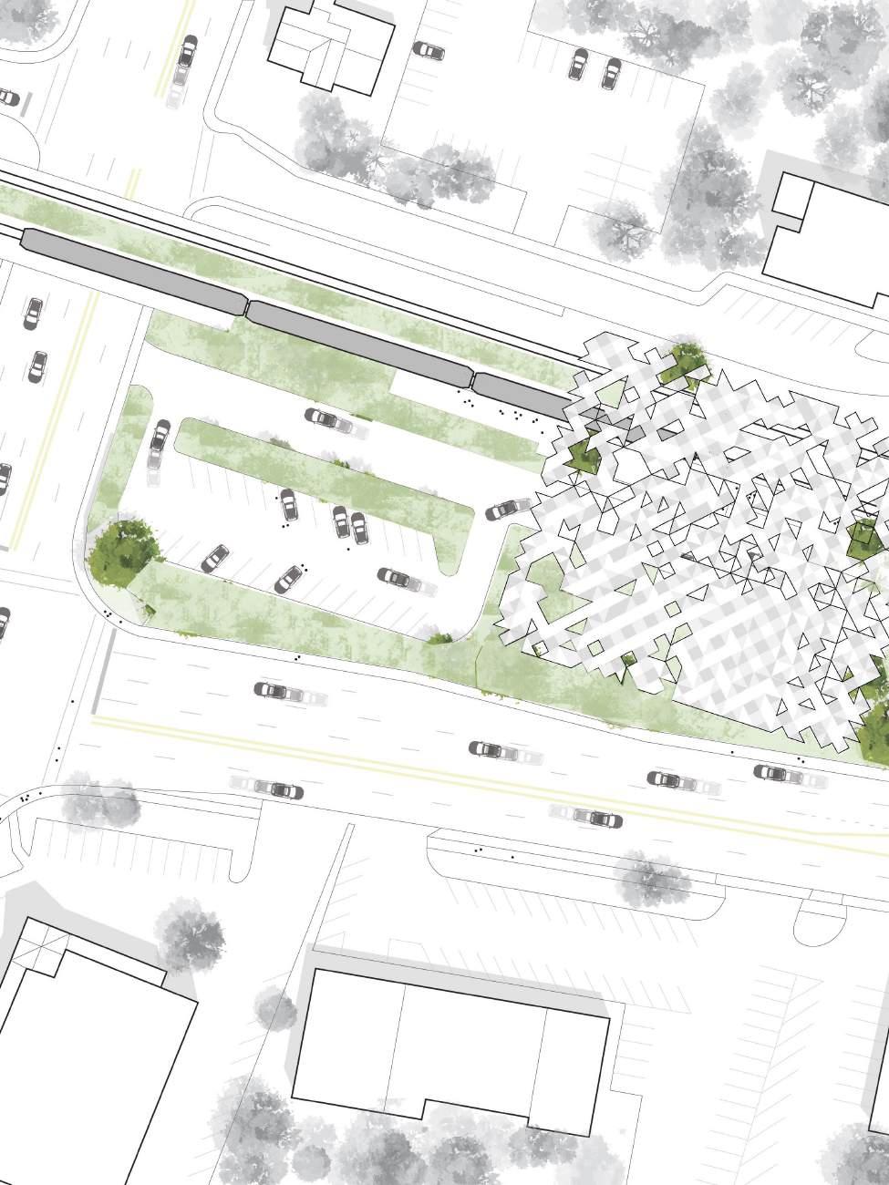
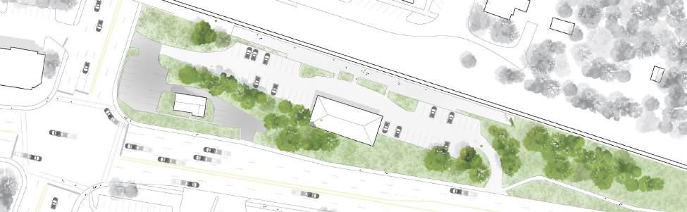
SITE PLAN The layout of housing units on the site.
SHELTER AND COMMUNITY
A crucial part of the design was to provide space for residents to gather and participate in cultural rituals. The hope was that these gathering spaces would encourage interactions and strengthen social infrastructure
among the residents, as well as solidify cultural traditions. Shown below is the Community Hub + Vertical Farm and a residential unit connected to a greenhouse (on right).
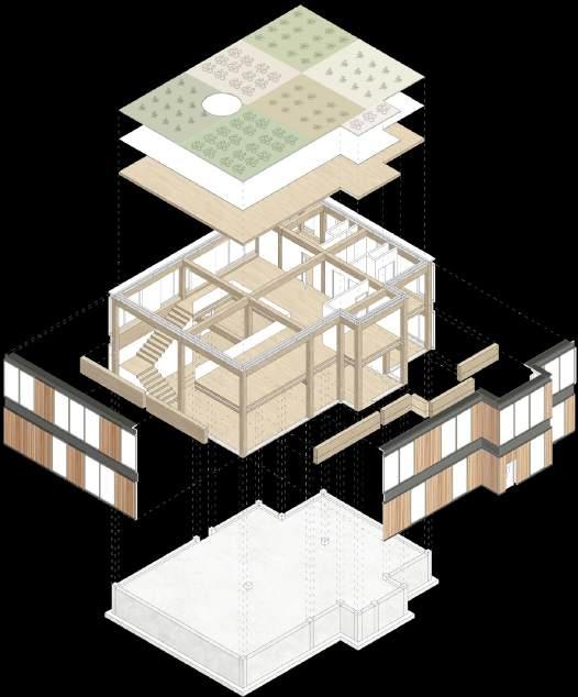
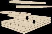
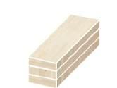
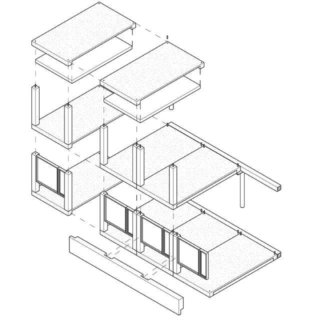
CROSS LAMINATED TIMBER
Since this site is prone to high winds, tornadoes, and small earthquakes from oil fracking, it was important to provide a stable structure. We chose to use mass timber for its dimensional stability and sustainable qualities (crosslaminated timber panels and glulam beams). We also wanted to incorporate a natural palette to the interior. The timber skeleton also contains three shear walls placed strategically like a tripod in order to support the unit in case of a seismic event. Finally, the unit is wrapped with Western red cedar, native to this region of the US and culturally significant to the Pawnee.
performative morphologies
GRAD. DESIGN STUDIO IV (PERFORMATIVE MORPHOLOGIES IN PRECAST CONCRETE) • TAUGHT
BY: MICHAEL CARLOS KLEISS, Ph.D. AND SIDA DAI, Ph.D. • CLAIRE HUSSEY (STUDIO PARTNER) • CLEMSON UNIVERSITY • SPRING 2024
The studies of generative principles of form have become central to our understanding of the diverse structures we encounter in nature and man-made constructs, both physical and conceptual. This is enabled by computation, fabrication, construction, and emerging technologies such as intelligence in generative design. This Morphology Research Studio conducted a research-based inquiry into grammars of design with an emphasis on structural form and performance. The studio focused on exploring the relations between geometry and topology (form and space), morphology and performance (form and force), dynamic morphology (time-based design), and morphology and kinetics (kinetic systems). The main purpose of this studio was to use morphological research to unveil the fundamental rules that govern the design of selected structures and to use this knowledge for the creation of new designs. At the same time, precast concrete as a material was the main area of emphasis when it came to research and exploration.
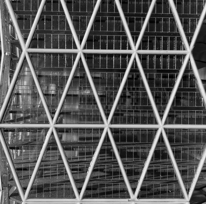
This studio had four stages. Stage One was Reconstruction; we worked in pairs to make a scale model of an existing building. My partner and I, Claire Hussey, chose to reconstruct Hearst Tower in New York City. This phase took about two weeks.
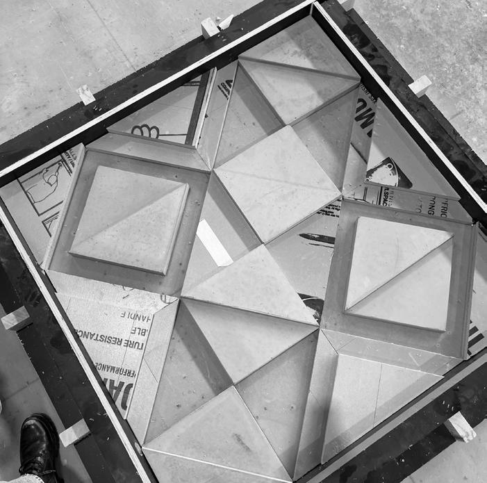
Stage Two was Morphogenesis where we were tasked with discovering the morphological source or fundamental unit of our reconstructed building. We determined the most interesting aspect of the building to be the ‘bird’s mouth’ corner condition. We experimented with origami folds to recreate this unique condition at different scales and dimensions (2D- flat paper and 3D- tower). The folds of the paper correspond to the corners on the tower at all three scales. We then determined our fundamental unit to be an individual unit from the 2D paper folds that could be 3D printed.
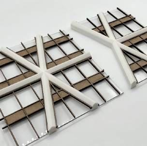
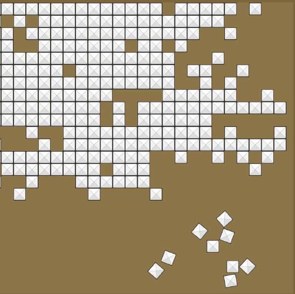
Stage Three was Generative Design where we then took our fundamental square unit and began iterating to generate unique design
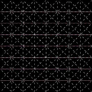
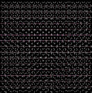
alternatives. We made eight design variations to our fundamental unit and 3D printed 25 of each type. We then made a board where we could lay out all of the pieces which was 22”x19.” Considering that each of the eight square tiles could be turned in four different positions, there were 4 variations of original layouts of tiles that could be arranged on the board.
Finally, Stage Four was called Design Synthesis. We were tasked with using all of the work we’d done so far and input it into a new building program of our choice. We decided to upgrade the City of Clemson, South Carolina’s existing AmTrack station by designing a new roof made of precast concrete. We used one of our tile layouts we created in Stage Three as the roof design for a new building.
For this studio, we were also fortunate to be able to attend the PCI Conference in Denver, CO February 6th-9th, 2024 and fabricate our own precast panel at Metromont in Greenville, SC. 418
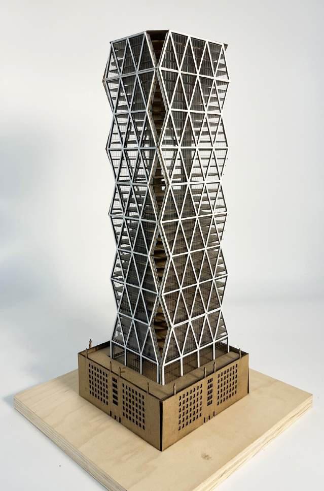
STAGE 01: RECONSTRUCTION
A representative model of Hearst Tower in New York City, designed by Foster + Partners. My studio partner and I, Claire Hussey, constructed this model using chipboard and acrylic, 3D printed the dia-grid, and customdesigned 3D printed spacers so each floor plate would be evenly spaced. This model stands at 2’-0” tall. We also made a larger scale model of just the facade.
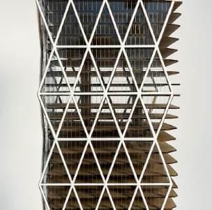
STAGE 02: MORPHOGENESIS
After the reconstruction phase, we determined the most interesting aspect of Hearst Tower to be the ‘bird’s mouth’ corner condition. We experimented with origami folds to recreate this unique condition at different scales and dimensions.
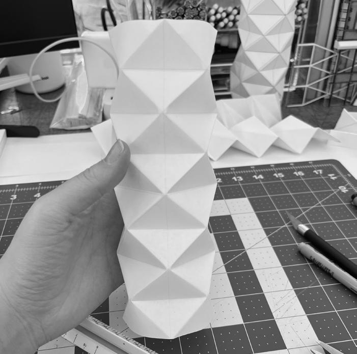
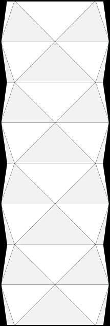
ORIGAMI SCALE A Origami tower made using 2” folds.
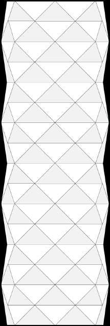
ORIGAMI SCALE B Origami tower made using 1” folds. This is the scale that we ended up moving forward with.
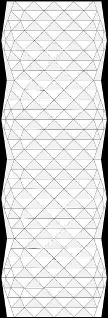
SCALE C Origami tower made using 1/2” folds.
ORIGAMI
ORIGAMI FOLDS SCALE A
ORIGAMI FOLDS SCALE B
ORIGAMI FOLDS SCALE C
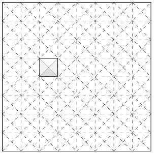
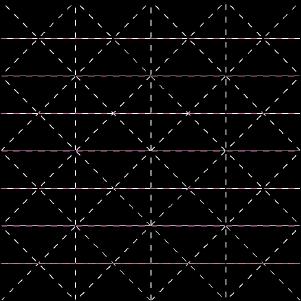
FUNDAMENTAL UNIT Above is the origami folds from ‘Origami Scale B.’ We derived our fundamental unit from this piece of paper. Since this scale of origami was 1,” our fundamental unit was a 1” square unit that we then 3D printed. The unit then had eight different variations which were guided by the fold lines that divide it, either pointing up or down.
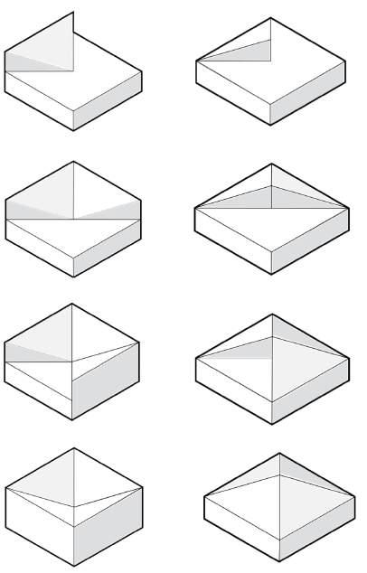
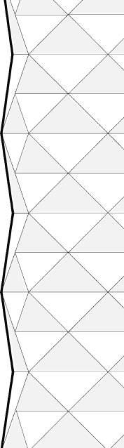
We determined our fundamental unit to be an individual unit from the 2D paper folds that could be 3D printed.
SITE PLAN: BEFORE Clemson Amtack Depot before intervention.
STAGE 03: GENERATIVE
DESIGN We made a 22”x19” board where we could lay out all of the 3D printed pieces. Considering that each of the eight square tiles could be turned in four different positions, there were 4 variations of original layouts of tiles that could be arranged on the board; almost an endless amount of possibilities.
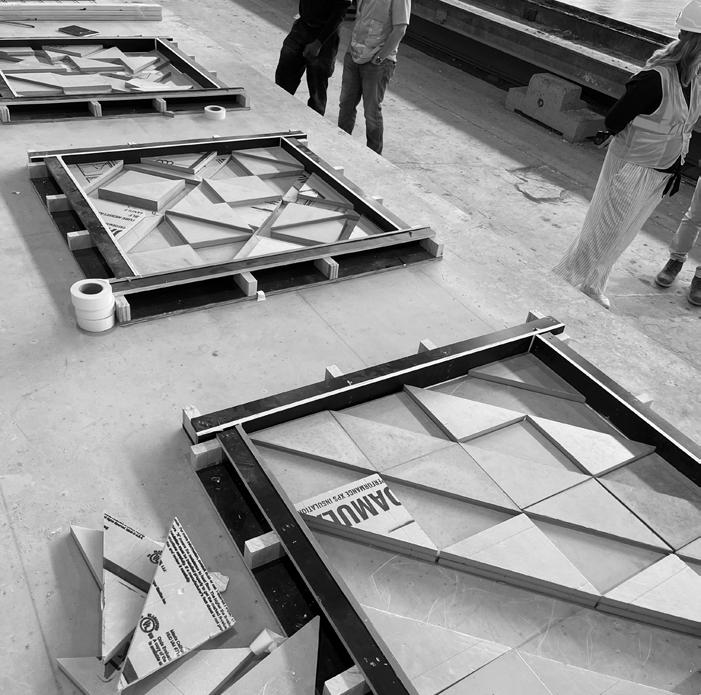
STAGE 04: DESIGN SYNTHESIS
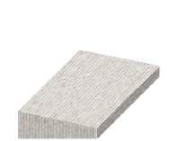
Using what we’d done so far, we decided to upgrade the City of Clemsons existing AmTrack station by designing a new roof made of precast concrete. We used one of our tile layouts we created in Stage Three as the roof design for a new building. Pictured right: precast fabrication.
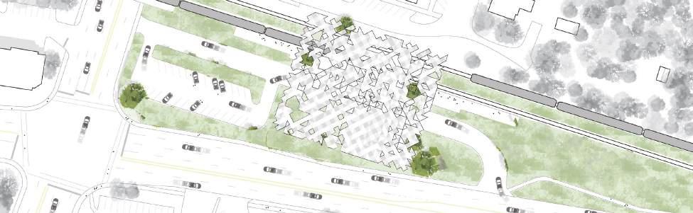
SITE PLAN: AFTER
Clemson Amtrack Depot after intervention.
izm building: a case study
BUILDING FACADES, SKINS, AND ENCLOSURES • TAUGHT BY:
TIM BROWN, AIA, NCARB • CLEMSON UNIVERSITY • SPRING 2024
Today’s facades and enclosure systems have become increasingly complex in order to deal with the many layers of considerations that must be made in order to ensure an efficient and beautiful building. Considerations include sunlight, water infiltration, temperature, energy generation, and all of the elements that go along with creating a sustainable envelope. This class focused a lot on how to balance getting the right amount of these elements in (sunlight, air,etc), but not too much to where it would become detrimental.
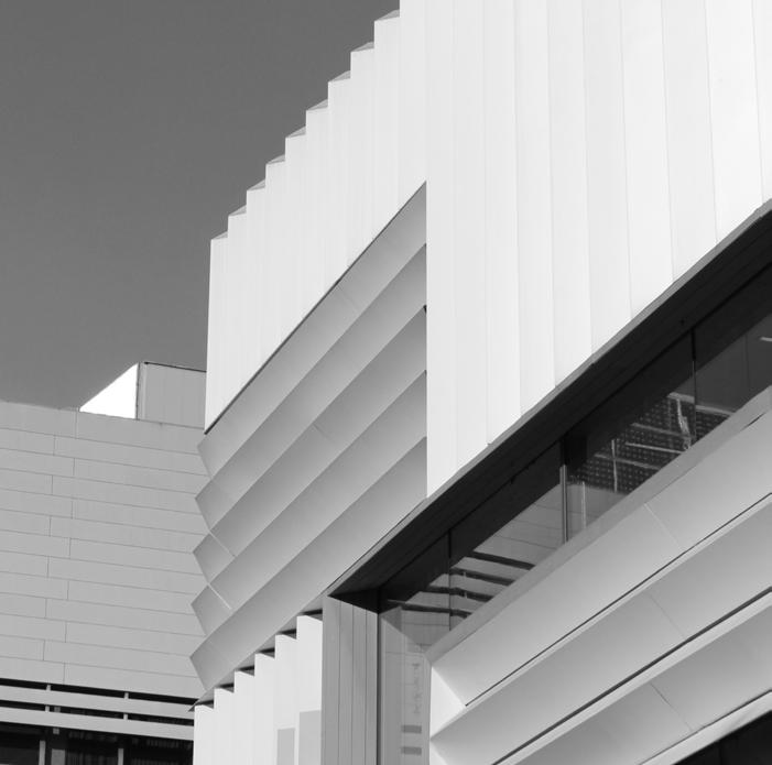
The beginning of the class discussed the three main categories: facade, skin, and enclosure. Each category is unique and has some differences between them, while sometimes there is some crossover. Then, the majority of the semester was spent researching a specific building and creating a case study analysis with a corresponding set of drawings. I chose to research the Illwerke Zentrum Montafon, or IZM building in western Austria. Designed by HK Architekten, the building sits on
a lake and is home to the Vorarlberger power company. The reason I chose this design is because I believe the architect did an impeccable job at balancing efficiency, material selection, and aesthetics. Most relevant to facade design, I chose the building because of the way it seamlessly integrated solutions to all of the previously mentioned building envelope challenges. Through researching the construction methods, materials, and details of this project, I discovered the importance of prefabrication, as well. I began by drawing the floor plans of the IZM building (referencing HK Architekten’s original plans). I then continued with the case study drawings by drawing a wall section with corresponding exterior and interior elevations, and an enlarged partial floor plan and reflected ceiling plan. These drawings were based on photos of the existing building and some educated guesses of structure based on literature from the architect.
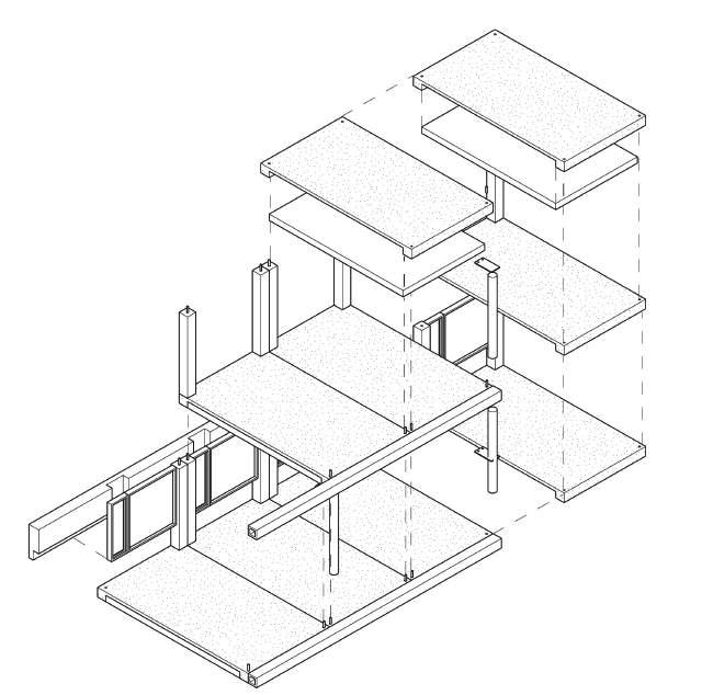
MODULAR EFFICIENCY
The IZM building featured a highly streamlined construction process thanks to prefabrication. The main components included concrete and timber. The facade modules fit into this puzzle seamlessly.


COORDINATED ORDER
Glulam members run parallel in the longitudinal direction (where it’s the strongest), allowing for long spans. This allows for uninterrupted views along the facade. The glulam beams carry and distribute the building’s load to its appropriatelyspaced columns (away from the views). The framing is aligned with the columns which seamlessly tie into the ceiling plane.


community park building
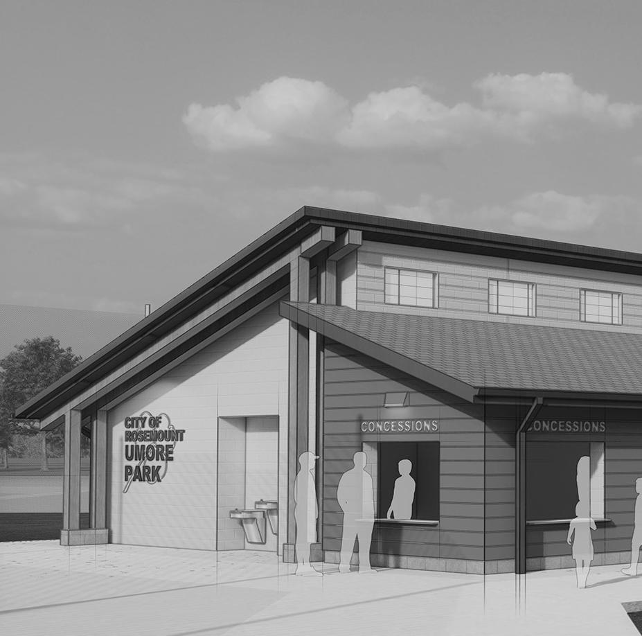
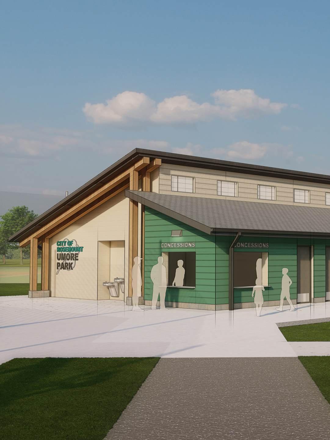
OERTEL ARCHITECTS • ANDREW COOPER, AIA • MADDY PETERS • PEYTON LARSON • CITY OF ROSEMOUNT, MN • SUMMER 2024
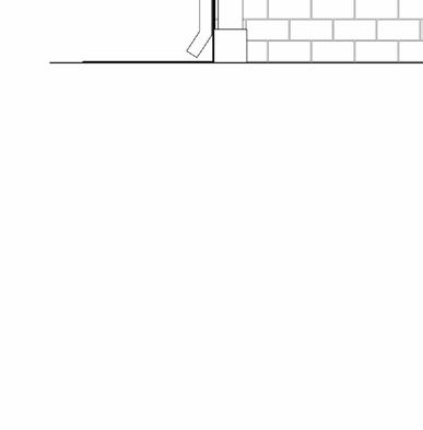
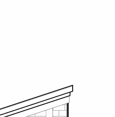
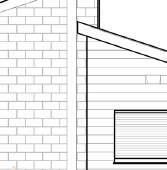
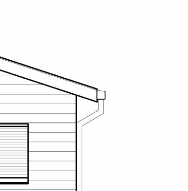
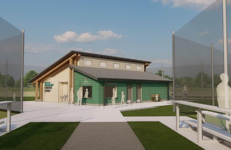
The City of Rosemount, MN was in need of a new concession and restroom facility on the site of a new small baseball/softball complex. The location of the building itself is in the center of four fields with access via sidewalk and pavement too all fields and the parking lot.
I designed, modeled, and rendered this building in 2023, and in 2024 I began the construction documentation process. For the design, I worked with the city’s Parks & Recreation Director to get a sense of what he wanted to see design-wise and in terms of function. The mayor also mentioned he wanted part of this building to be green to symbolize the city’s identity, since green was part of their logo and city colors. The design itself went through many iterations, but ultimately we landed on one that pleased all parties involved and moved forward.
In 2024, I was able to move forward with the construction documentation phase in Revit. Together with my coworkers, Maddy Peters and Peyton Larson, I spent the majority of my time
modeling and detailing the building while collaborating with our structural and M/E consultants. With assistance from my coworker Andrew Cooper, AIA, I was also able to play a large part in the process management side and lead consultant check-in meetings during this phase of design development. All construction documents have now been completed and construction has started as of January 2025. This building is set to be completed in June 2025.


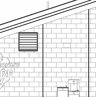
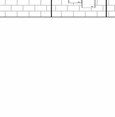

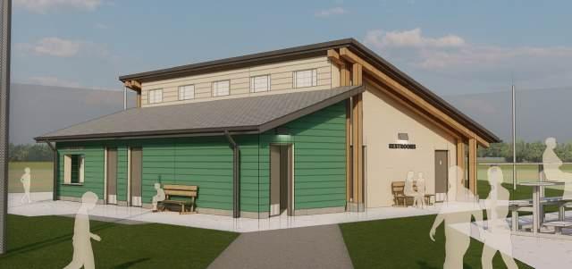
A COMMUNITY SPACE


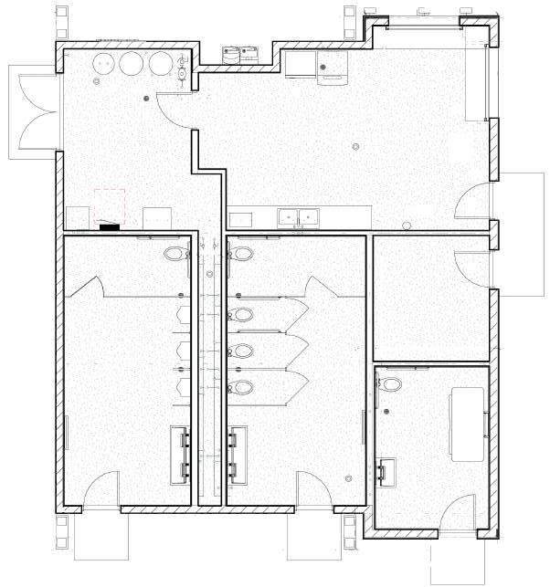

The program called for a flex space to serve concessions, men’s and women’s restrooms, a family restroom, an office, and space for mechanical features. This project also has an accessible plumbing chase that can be accessed through the mech/elec room.

THE LOOKOUT
GRAD. DESIGN STUDIO V (AMERICA’S CUP SAILING COMPETITION
PUBLIC VENUE AND RESIDENCES) • TAUGHT BY: MIGUEL ROLDAN, MERCEDES BERENGUÉ, AND DAVID ESPUÑA • CLEMSON UNIVERSITY + BARCELONA ARCHITECTURE CENTER) • FALL 2024
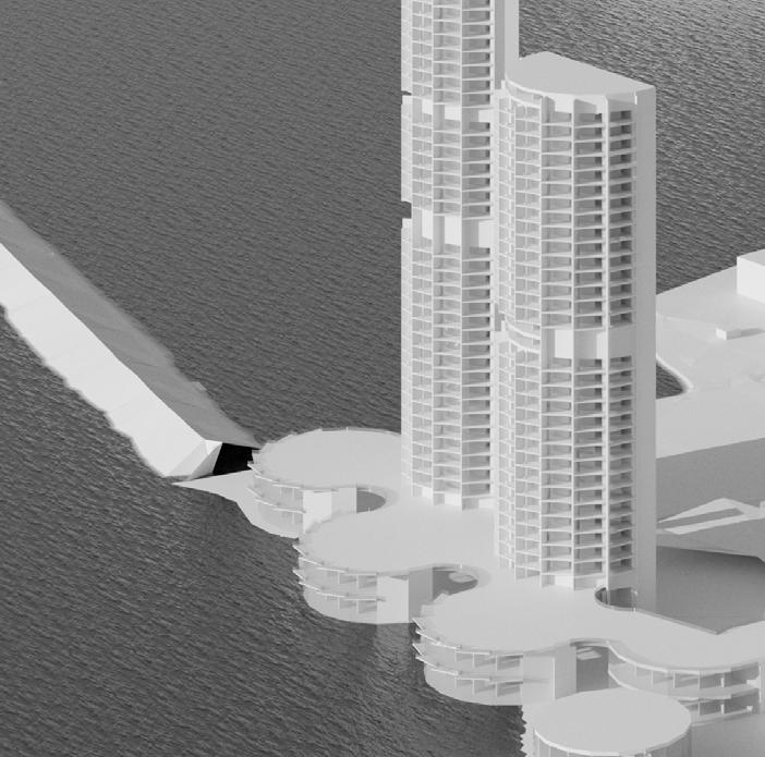
The Lookout is a large-scale urban intervention that takes into consideration both the land and the sea. The original building that existed on the site (the W Hotel), didn’t do much to consider both of these factors, but rather acted only as a beacon or monument to be recognized from afar. The Lookout, with its back to the land (including Barcelona and the Collserola Mountains), takes note of this condition by incorporating green space within the residence towers, while unobstructed views to the sea are included where the building opens up to the Mediterranean. At any given moment, an inhabitant can turn and experience either phenomenon. Instead of acting only as a beacon to be seen, The Lookout was influenced by the views the building itself could offer to its inhabitants. The Lookout also strives to be more publicly inclusive and seeks to be re-used once the America’s Cup sailing race concludes. The first intervention was to carve out the beach and create more usable land for the public to enjoy.
Each building was placed on the site as to not obstruct the view of another. The structural shear walls are also extended in such a way as to shield the intense sun that hits from the South and to provide privacy on the balconies for residents to feel as though they have their own personal nook in the tower. There are three residential floor plates: one that has no cut-out which allows for a full-floor green space, one that has a small cut-out, and one with a large cut-out. All residential plans have ample room for residents to circulate in an open air hallway that connects to the stair and elevator cores. These residential floor plates are mixed within the two residence towers and include an two-story restaurant and spa mixed within. The public is free to use any of the amenities in the residence towers as they are public spaces and can be accessed from the main promenade. The double-height Team Venues offer open exhibition and viewing space and connect to the residence towers via the Viewing
Platform. The Viewing Platform is located on Level 2 (the roof of the Team Venues) and connects all of the spaces together. The Viewing Platform can be accessed from every location of the site and you can get to any location on the site from the Viewing Platform. The Platform allows the public to view the America’s Cup race, but more importantly, the space allows for the city of Barcelona to continue to connect and interact with each other once the race concludes.
Barcelona could benefit greatly from a large beach front intervention which also acts as a connection point to a variety of architectural interventions. After the America’s Cup’s conclusion, the Team Venues could be used for exhibition or recreation spaces which are already connected to the two large residential towers. The Lookout aims to be a more publicly inclusive project that can be adapted to fit the needs of Barcelona for years to come.


Instead of acting only as a beacon to be seen, ‘The Lookout’ was influenced by the views the building itself could offer to its inhabitants.
FLOOR PLANS The residential floor plates are mixed within the two residence towers and include an two-story restaurant and spa mixed within.
PUBLIC SPACE The Viewing Platform is located on Level 2 (the roof of the Team Venues) and connects all of the spaces together. The Viewing Platform can be accessed from every location of the site and you can get to any location on the site from the Viewing Platform. The Platform allows the public to view the America’s Cup race, but more importantly, the space allows for the city of Barcelona to continue to connect and interact with each other once the race concludes.


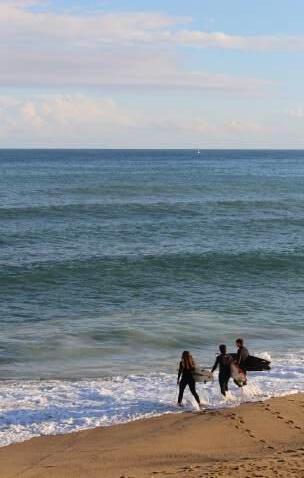
STUDY ABROAD PHOTOGRAPHY
CANON REBEL EOS T5i • BIBLIOTECA GABRIEL GARCÍA MÁRQUEZ (BARCELONA, CATALONIA): SUMA Arquitectura.
taken December 3, 2024.
Photo
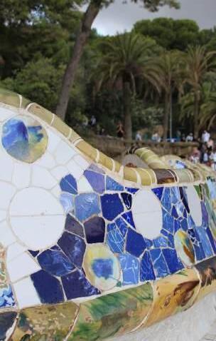
PARK GÜELL (BARCELONA, SPAIN): Antoni GaudÍ. Photo taken September 19, 2024.
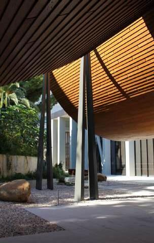
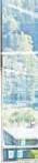
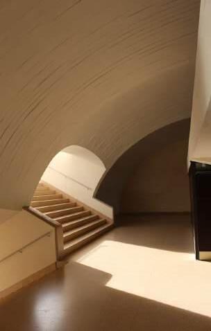
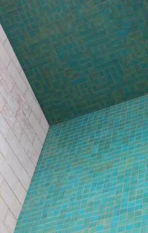
CENTRO DE ARTE MODERNA GULBENKIAN (LISBON, PORTUGAL): Kengo Kuma. Photo taken October 22, 2024.
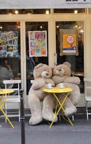
TABLE FOR TWO (PARIS, FRANCE): Photo taken December 1, 2024.
HIPÓDROMO DE LA ZARZUELA (MADRID, SPAIN): Carlos Arniches, MartÍn DomÍnguez, Eduardo Torroja. Photo taken October 2, 2024.
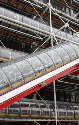
CENTRE POMPIDOU (PARIS, FRANCE): Richard Rogers, Renzo Piano. Photo taken December 1, 2024.
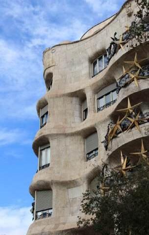
LA PEDRERA - CASA MILÀ (BARCELONA, SPAIN): Antoni GaudÍ. Photo taken December 7, 2024.
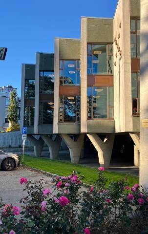
HAUGESUND PUBLIC LIBRARY (HAUGESUND, NORWAY): David Sandved. Photo taken September 20, 2024.
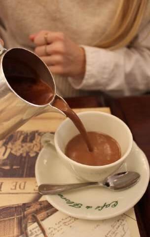
CAFÉ DE FLORE (PARIS, FRANCE): Photo taken November 29.
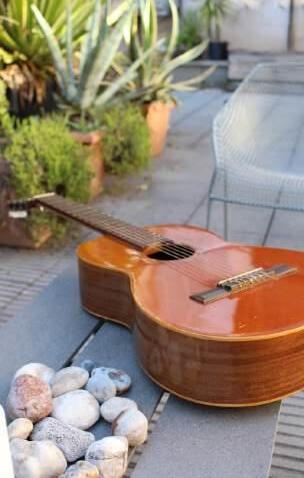
ACOUSTIC (BARCELONA, SPAIN): Photo taken November 28, 2024.
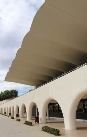
HIPÓDROMO DE LA ZARZUELA (MADRID, SPAIN): Carlos Arniches, MartÍn DomÍnguez, Eduardo Torroja. Photo taken October 2, 2024.
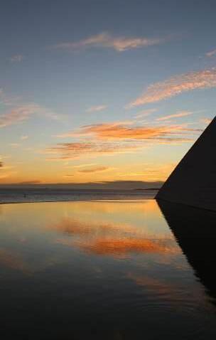
‘98 EXPO. PORTUGUESE NATIONAL PAVILION (LISBON, PORTUGAL): Álvaro Siza. Photo taken October 21, 2024.
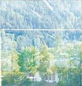
MIRADOURO DA FUNDAÇÃO CHAMPALIMAUD (LISBON, PORTUGAL): Charles Correa. Photo taken October 21, 2024.
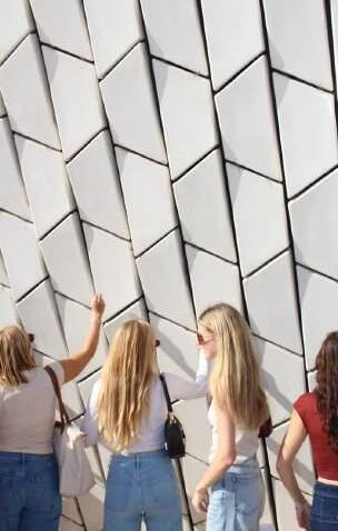
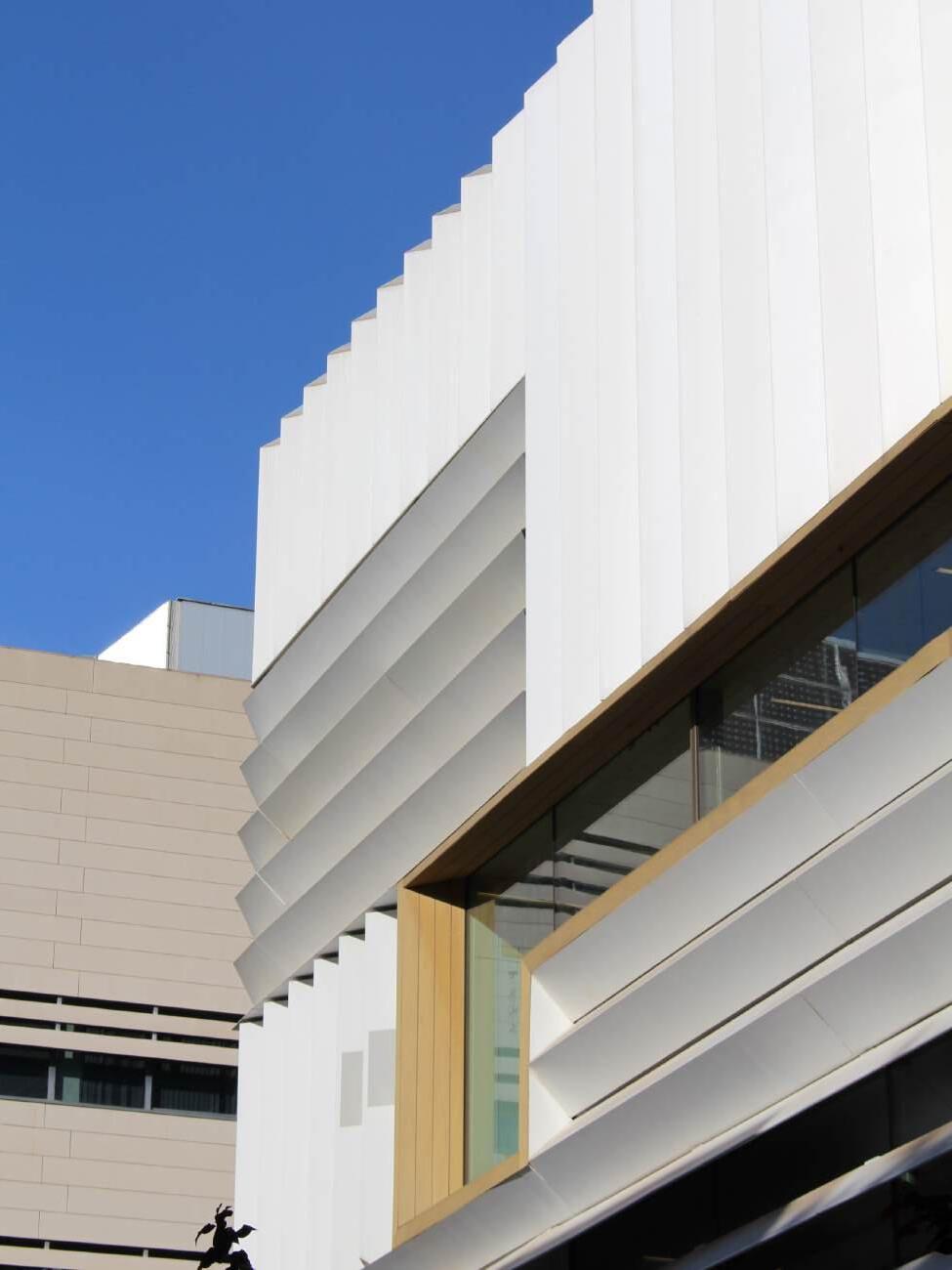
MUSEUM OF ART, ARCHITECTURE AND TECHNOLOGY (LISBON, PORTUGAL): AL_A. Photo taken October 21, 2024.
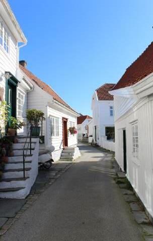
FISHING VILLAGE (SKUDENESHAVN, NORWAY): Photo taken September 21, 2024.
December 13, 2024.
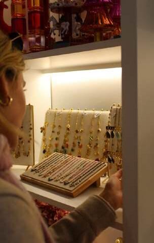
JEWLERY
SHOPPING (PARIS, FRANCE): Photo taken November 29, 2024.
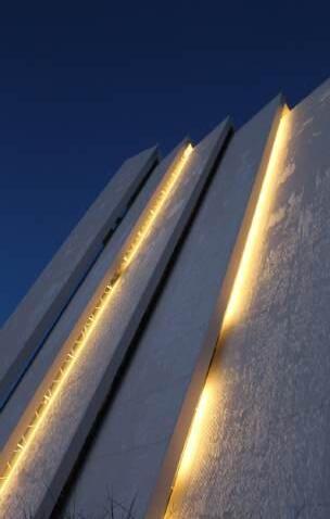
CATHEDRAL (TROMSØ, NORWAY): Jan Inge Hovig. Photo taken November 20, 2024.
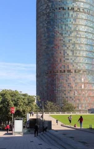
GLÒRIES TOWER (BARCELONA, SPAIN): Jean Nouvel. Photo taken November 14, 2024.
ARCTIC
SANT MIQUEL BEACH (BARCELONA, SPAIN): Photo taken