East (access off Main St.) North (Benson St.)


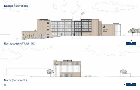
East (access off Main St.) North (Benson St.)
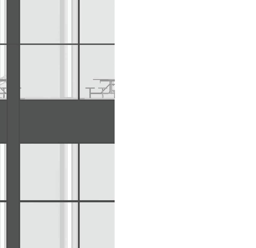
2X WOOD BLOCKING
METAL PARAPET CAP
CANT STRIP
WATER-RESISTANT MEMBRANE
PLYWOOD SHEATHING
RIGID AND TAPERED INSULATION


18”
3-PLY CLT ROOF PANEL
METAL CLADDING SPANDREL (GRAY)
6” METAL STUD
FIRE SEAL
RIGID INSULATION
METAL CLADDING SPANDREL
METAL BACKPAN (BLACK)
KAWNEER MULLION SYSTEM
GLAZING
BEYOND
GLAZING
FIRE SEAL
2” CONCRETE TOPPING ACOUSTIC MAT
5-PLY CLT FLOOR PANEL
18” GLULAM COLUMN BEYOND 8 3/4” X 18” GLULAM BEAM
RIGID INSULATION
METAL CLADDING SPANDREL
METAL BACKPAN KAWNEER MULLION SYSTEM
18” X 18” GLULAM COLUMN BEYOND
2” CONCRETE TOPPER (POLISHED)
4” CONCRETE SLAB ON GRADE VAPOR RETARDER
8” GRANULAR BASE
BACKER ROD & SEALANT
METAL FLASHING
RIGID INSULATION
GRAVEL DRAINAGE PERIMETER
DRAIN PIPE
CONCRETE PAVEMENT
C.I.P. CONCRETE FOOTING BEYOND
EDUCATION OCCUPANCY
ASSEMBLY OCCUPANCY (A-1 AND A-4)
2-HOUR RATED WALL
1-HOUR RATED WALL
COMMON PATH
EGRESS PATH

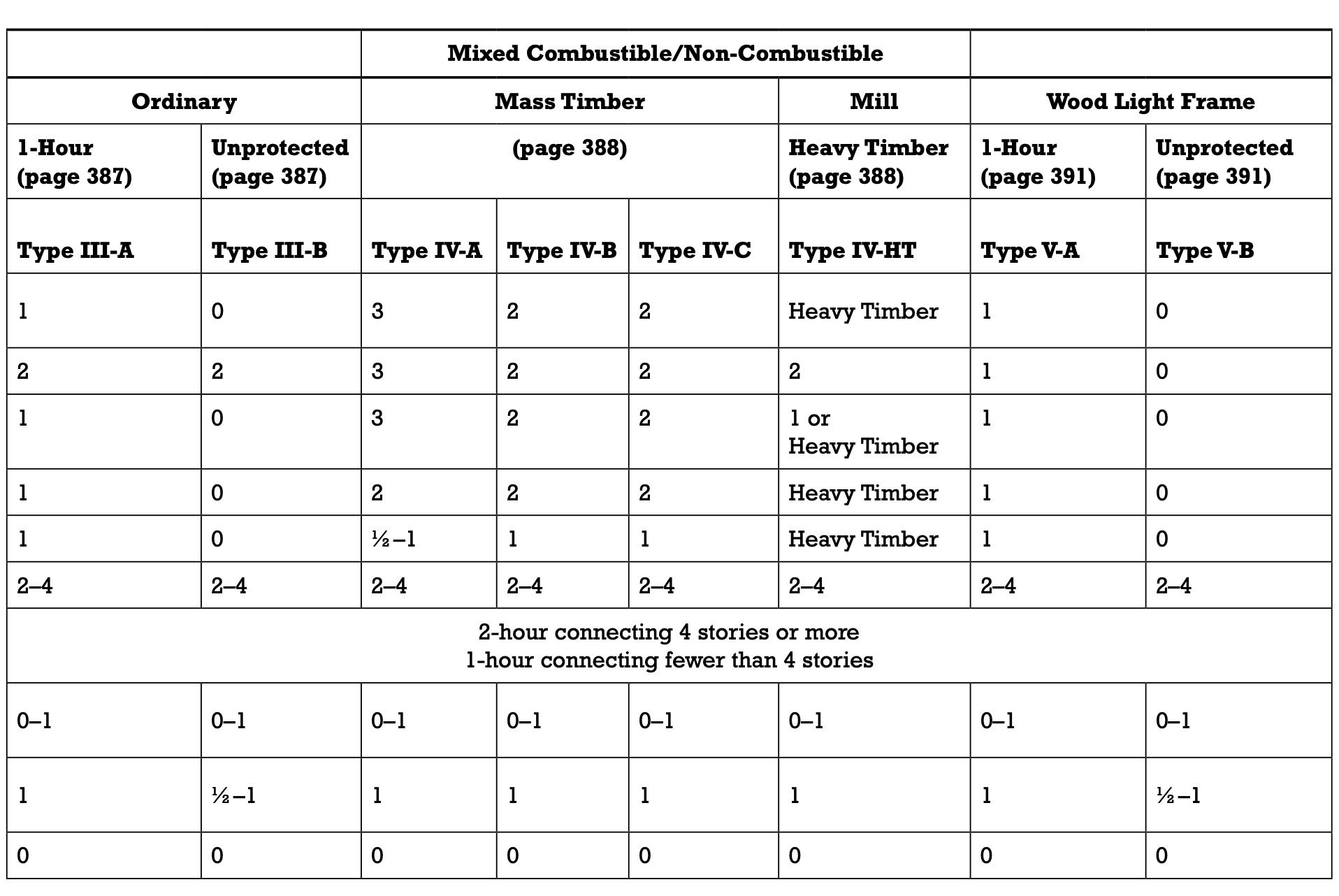
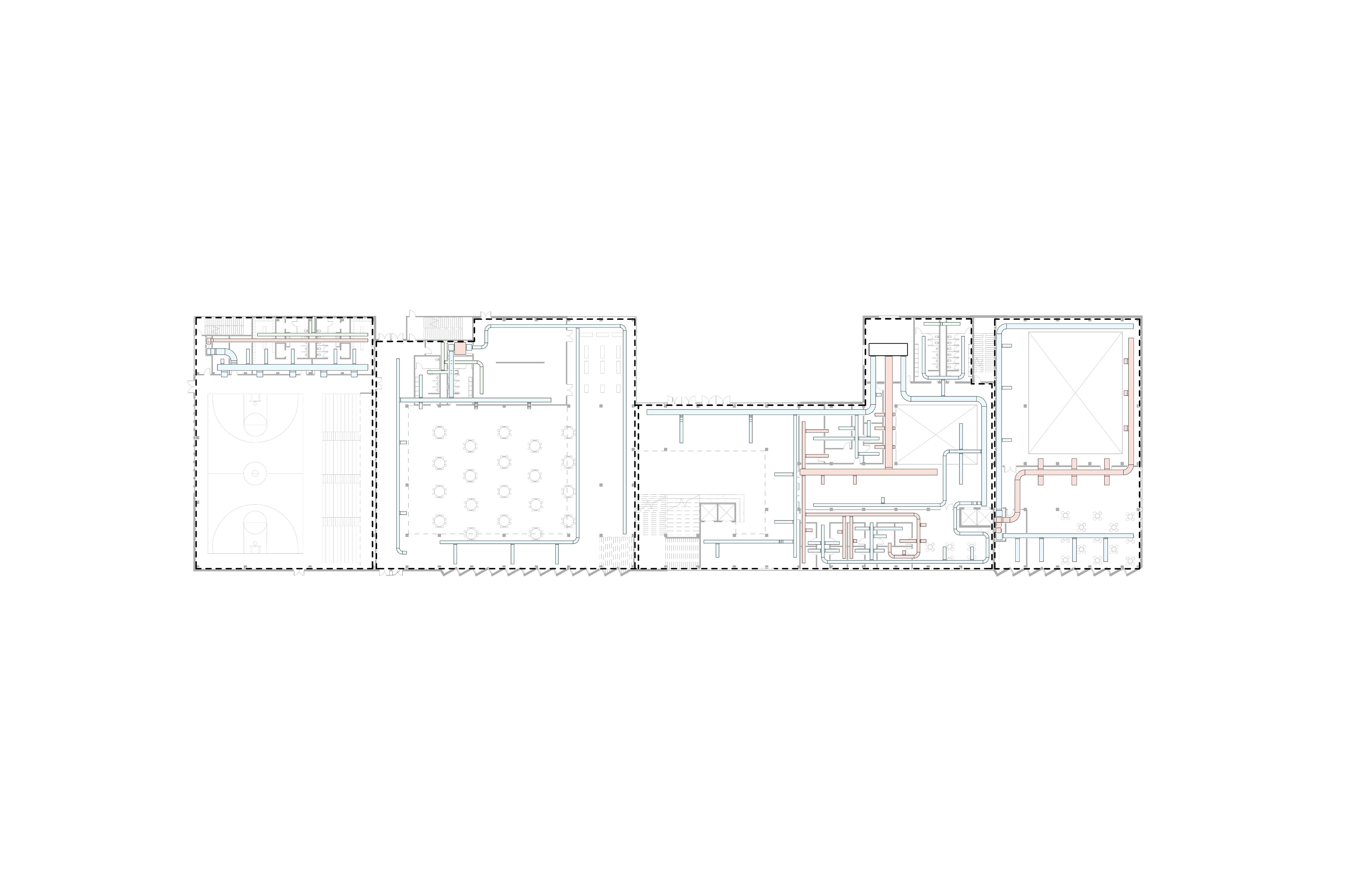
Chapter 7, Section 1 (p. 389)
Mixed Combustible / Noncombustible Construction Type IV-HT (Sprinklered): Mass Timber
Building Totals
Code Minimums
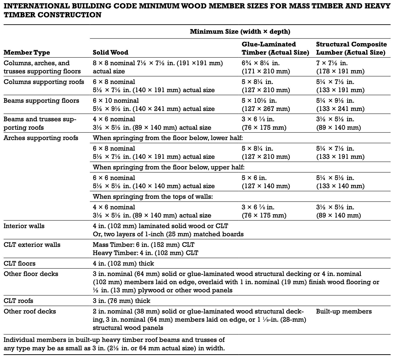
minimum allowed size of solid wood interior walls:
in.
7/8 in.
minimum allowed size of solid wood CLT floors:
in.
7/8 in.
minimum allowed size of solid wood CLT exterior walls:
in.
minimum allowed size of glue-laminated timber columns, arches, and trusses supporting floors:
3/4 x 8 1/4
minimum allowed size of glue-laminated timber columns supporting roofs: 5 x 8 1/4 Our Building
x 18”
x 18”
minimum allowed size of glue-laminated timber beams supporting floors: 18” x 24” (smallest beam) 5 x 10 1/2
Chapter 7, Section 1 (p. 382-383)
Mixed Combustible / Noncombustible Construction Type IV-HT (Sprinklered): Mass Timber
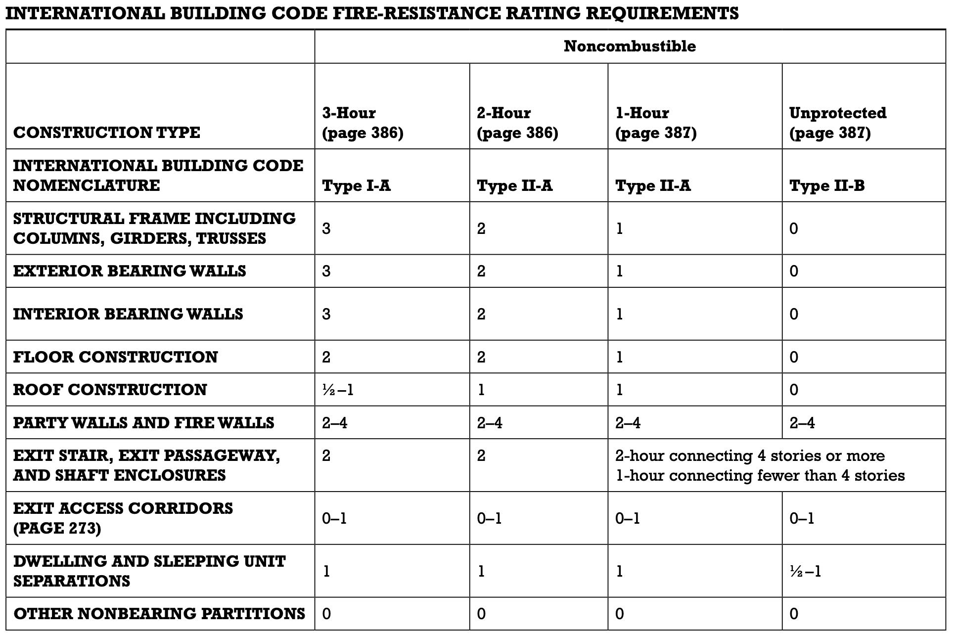
Building Requirements
Structural Frame Including Columns, Girders, Trusses
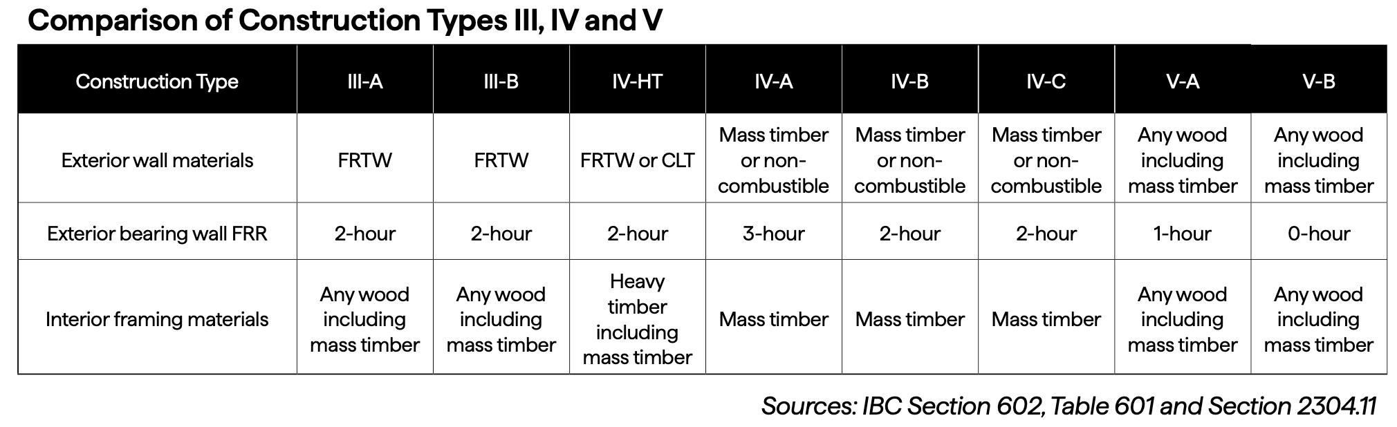
WoodWorks Mass Timber Handbook (p. 77)
Mixed Combustible / Noncombustible Construction Type IV-HT (Sprinklered): Mass Timber
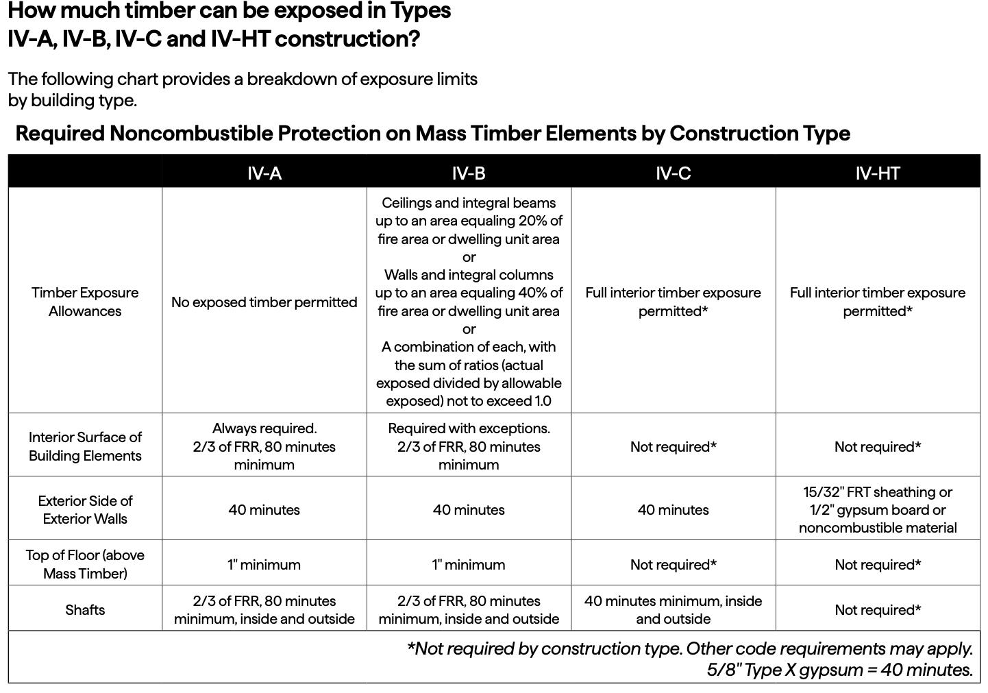
A shaft is defined by the IBC as “any enclosed space extending through one or more stories of a building, connecting vertical openings in successive floors, or floors and roofs.”
This applies to stairs, elevators, and mechanical/electrical/plumbing (MEP) chases in multi-story buildings.
Chapter 7, Section 2 (p. 408-409)
Educational (E) Occupancy
Mixed Combustible / Noncombustible
Construction Type IV-HT (Sprinklered): Mass Timber
Code Allowances Our Building
maximum allowed building height:
any
*first two floors (below grade) are concrete construction (Type IA); timber construction begins on Ground Level
**if building is single story, maximum area for that story is allowed to be 102,000 SF; our building is multi-story, therefore each floor can’t exceed 76,500 SF
x54 Column Footings Continuous Stem Wall
262,283 lbs/col.
5’ x 5’ *includes column footings integrated with stem wall
x60 Column Footings Continuous Stem Wall
Concrete Column
x 24”
Concrete Wall
Shear Wall
Core
Cast-in-Place
Cast-in-Place
Depths vary based on span
Core
5-Ply CLT Panels
11’ x 40’
Some variance in size based on location
Depths vary based on span
Core
Shear Wall Core
5-Ply CLT Wall Panels
Glulam Beam Depths vary based on span
Shear Wall Core
Cast-in-Place Concrete
GLULAM
3/4 x 24 GLULAM
3/4 x 36 GLULAM 8 3/4 36 GLULAM 8 3/4 x 36 GLULAM 8 3/4 x 24 GLULAM 8 3/4 18 GLULAM
3/4 x 24 GLULAM
Glulam Column
18” x 18”
Shear Wall Core
5-Ply CLT Wall Panels
Shear Wall Core
Cast-in-Place Concrete
Cross
Bracing
Shear Wall Core
Shear Wall Core
5-Ply CLT Wall Panels
Shear Wall Core
5-Ply CLT Wall Panels
Shear Wall Core
11’ x 40’
Some variance in size based on location
Shear Wall Core
5-Ply CLT Wall Panels
Glulam Beam Depths vary based on span
Glulam Column
18” x
Shear Wall Core
5-Ply CLT Wall Panels
Shear Wall Core
Cast-in-Place Concrete
Cross Bracing
Shear Wall Core
Shear Wall Core
5-Ply CLT Wall Panels
Shear Wall Core
5-Ply CLT Wall Panels
Shear Wall Core
11’ x 40’
Some variance in size based on location
Shear Wall Core
5-Ply CLT Wall Panels
Glulam Beam
Depths vary based on span
3/4 x 24 GLULAM 8 3/4 x 24 GLULAM 8 3/4 x 24 GLULAM 8 3/4 x 24 GLULAM 8 3/4 x 30 GLULAM 8 3/4 x 24 GLULAM 8 3/4 x 18 8 3/4
3/4 x 30 GLULAM 8 3/4 x 24 GLULAM
3/4 30 GLULAM
3/4 x 30 GLULAM
3/4 x 30 GLULAM
3/4 x 30 GLULAM
3/4 x 18 GLULAM
3/4 x 24 GLULAM
x
3/4 x 30 GLULAM 8 3/4 x 30 GLULAM 8 3/4 x 24 GLULAM
3/4 x 24 GLULAM 8 3/4 x 24 GLULAM 8 3/4 x 24 GLULAM 8 3/4 x 24 GLULAM 8 3/4 x 24
3/4 x 24 GLULAM
3/4 x 24 GLULAM
Shear Wall Core
Cast-in-Place Concrete
Glulam Column
Shear Wall Core
5-Ply CLT Wall Panels
3/4 x 24 GLULAM 8 3/4 24 GLULAM
Cross Bracing
Shear Wall Core
Shear Wall Core
5-Ply CLT Wall Panels
Shear Wall Core
5-Ply CLT Wall Panels
Shear Wall Core
11’ x 40’
Some variance in size based on location
Shear Wall Core
5-Ply CLT Wall Panels
x 30 GLULAM
8 3/4 x 18 GLULAM 8 3/4 x 18 GLULAM
8 3/4 x 30 GLULAM
Glulam Beam Depths vary based on span
8 3/4 x 30
x
3/4 x 24 GLULAM 8 3/4 x 24 GLULAM 8
Glulam Column
18” x 18”
Shear Wall Core
5-Ply CLT Wall Panels
Shear Wall Core
Cast-in-Place Concrete
Beam Depths vary based on span
Column 18” x 18”
Shear Wall Core
Shear Wall Core
5-Ply CLT Wall Panels
Shear Wall Core
5-Ply CLT Wall Panels
Wall Core
Some variance in size based on location
Shear Wall Core
5-Ply CLT Wall Panels
Shear Wall Core
Cast-in-Place Concrete
3-Ply CLT Roof Panels
11’ x 40’
Some variance in size based on location
Summary of Systems
5-Ply CLT Floor Panels with 2” Concrete Topping Slab
3-Ply CLT Roof Panels
5-Ply CLT Vertical Shaft / Core Walls
Glulam Columns
Glulam Beams + Girders
2” Steel Cables
Cast-in-Place Concrete Columns
Cast-in-Place Concrete Beams
Cast-in-Place Concrete Retaining Walls
4” Concrete Slab on Grade
3-Ply CLT
Roof Panels
6 7/8 thickness
11’ x 40’ panels
Glulam Beams
8 3/4 “ x 24”
Distributed load from CLT floor panels (above)
5-ply CLT
Floor Panels
6 7/8 “ thickness 11’ x 32’ panels
Glulam Beams
8 3/4 “x 18”
*no load here since CLT floor panels run parallel to beam
Timber Levels
Concrete ‘Podium’ Levels
Concrete Beams
Cast-in-Place
Concrete
Retaining Wall
Cast-in-Place
Concrete Footings
Cast-in-Place
Shallow Footings: Column Footings to Continuous Stem Wall Footings
Point Loads
Recieved on glulam girders from glulam beams over atrium spaces
Glulam Girders
8 1/2 x 36”
Recieve point loads from glulam beams
Glulam Columns
18” x 18”
Cross-Bracing
Steel cables
Tension and compression
Timber Levels
Concrete ‘Podium’ Levels
Concrete Slab
4” thickness
Concrete Shear Wall / Elevator Core
Cast-in-Place
Concrete Columns
24” x 24”
Cast-in-Place
Concrete Footings
5’ x 5’
Cast-in-Place
Shallow Footings: Column Footings


(Gymnasium, Locker Rooms, and Weight Room)
/
Line, Mezzanine, Classrooms)
C (Main Stair Atrium, Library, Community Collab, Admin Suite, Art + Music Rooms, Wood Shop, Mech Room)
(Black Box Theater + Commons)
Zone C -2: Education
Zone A: Gymnasium & Locker Rooms
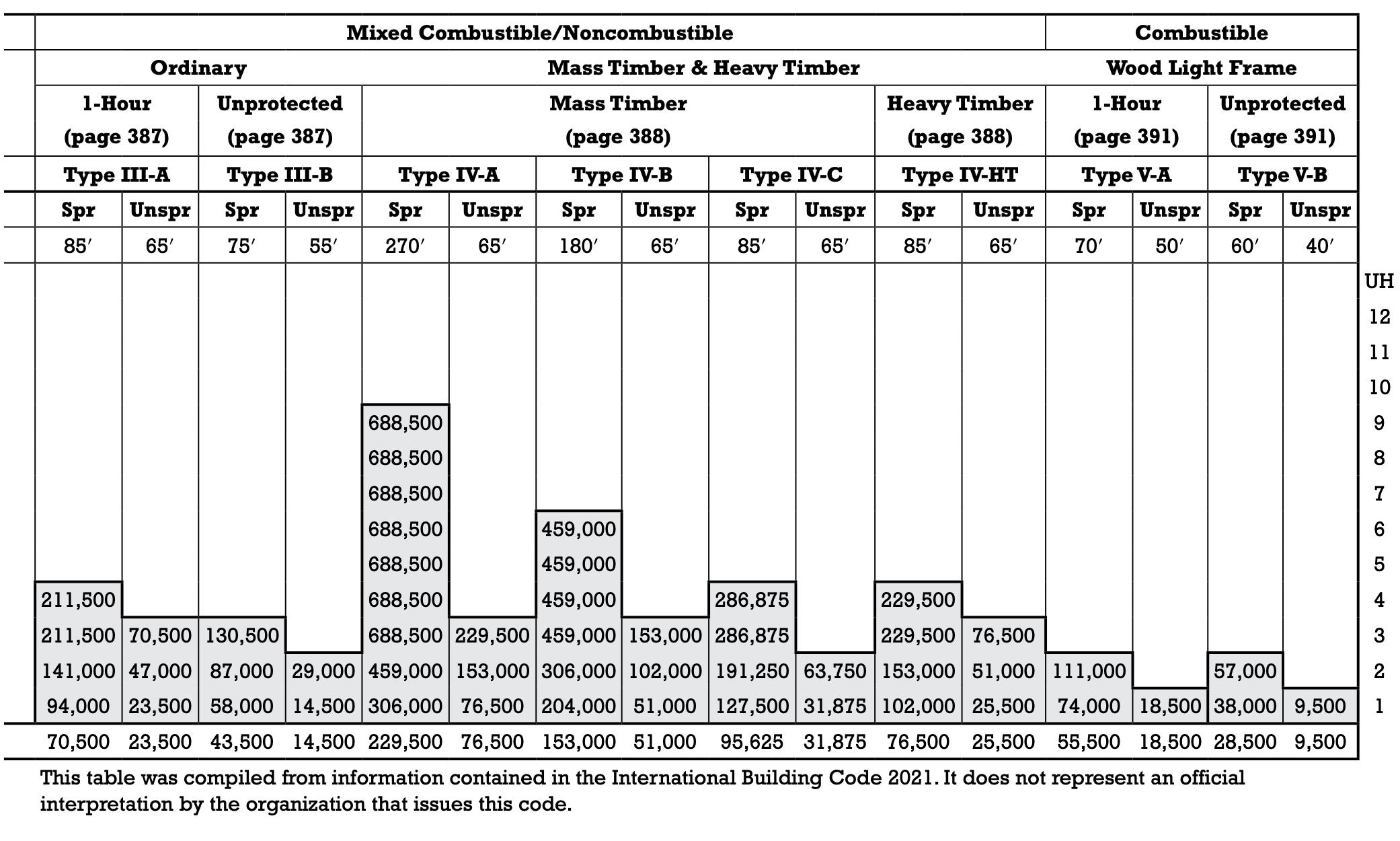
CAV, RTU
Mech. Shaft
Connects to RTU #1
Mech. Shaft
Connects to RTU #2
Zone B: Education VAV,
Zone C: Education VAV, Fan Room
ft2 (just Level 1)
Mech. Shaft Connects to RTU #3
Zone D: Theater & Commons
Mech. Shaft
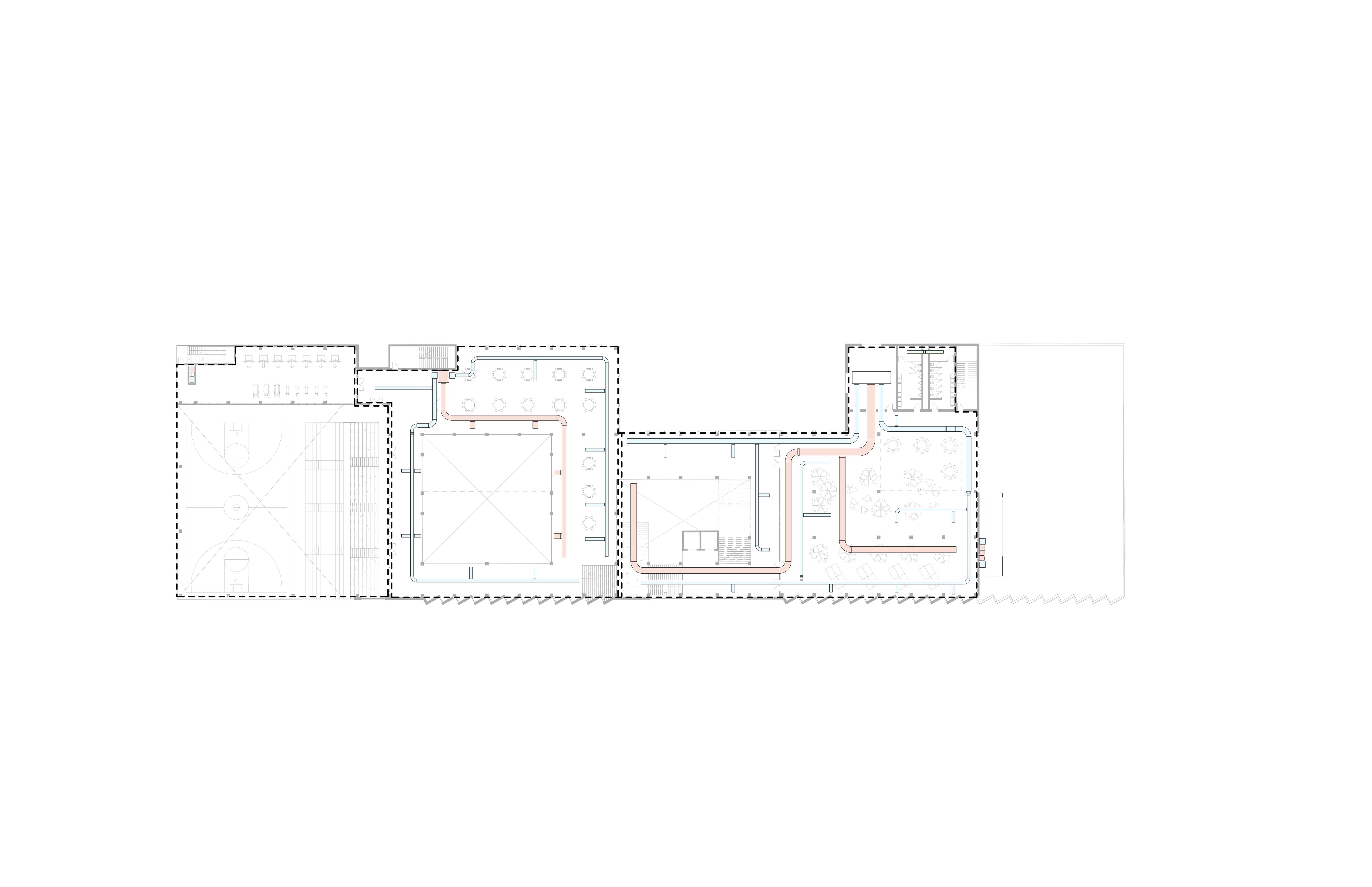
Shaft
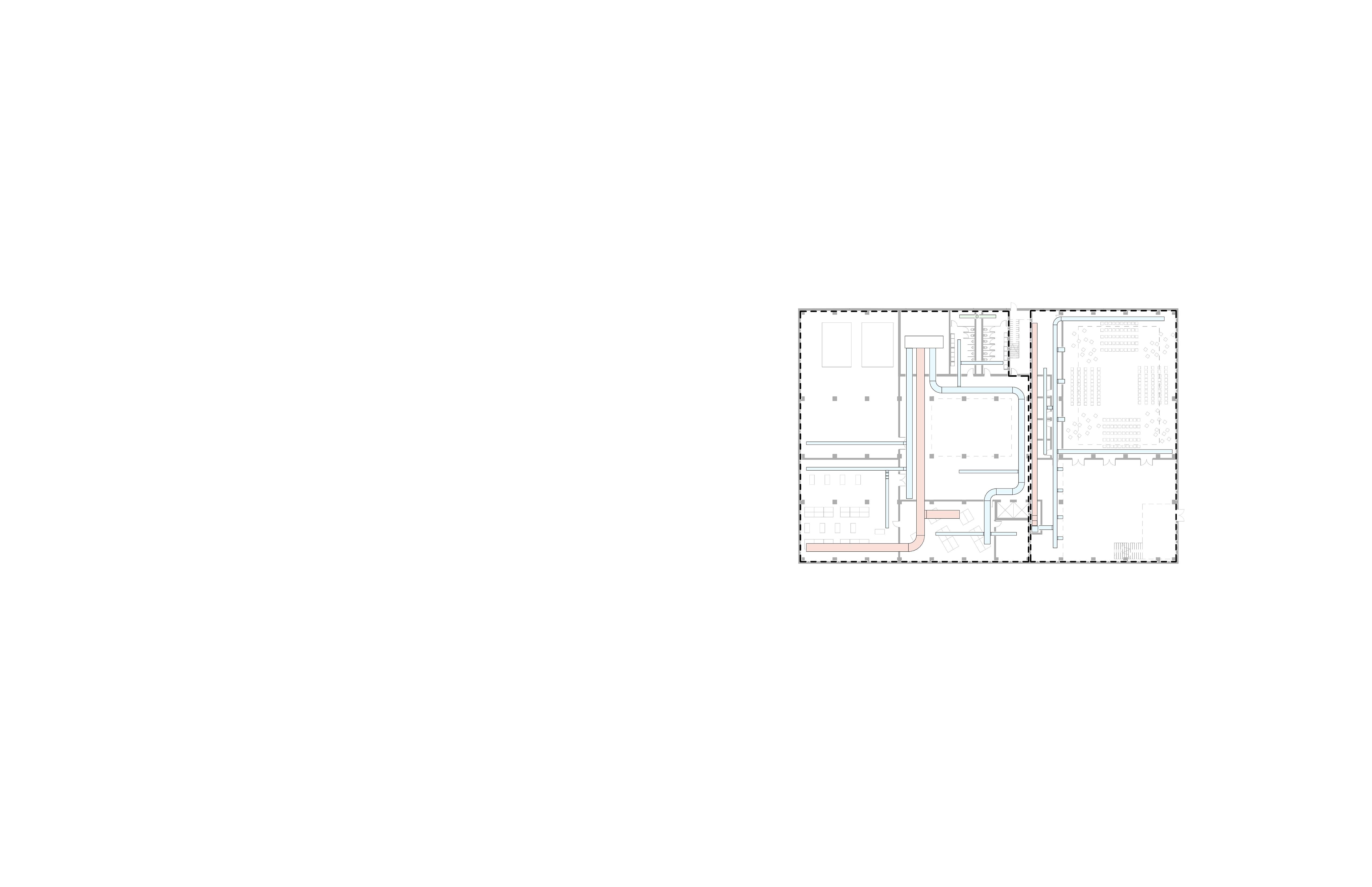
Zone A: Gymnasium
CAV, RTU 12,411 ft2 (includes Levels 1-3)
Ductwork shown on Level 3
Zone B: Education VAV, RTU
ft2 (includes Levels 1-4)
Zone C: Education VAV, Fan Room
ft2 (just Level 2)
Mech. Shaft
Connects to RTU #1
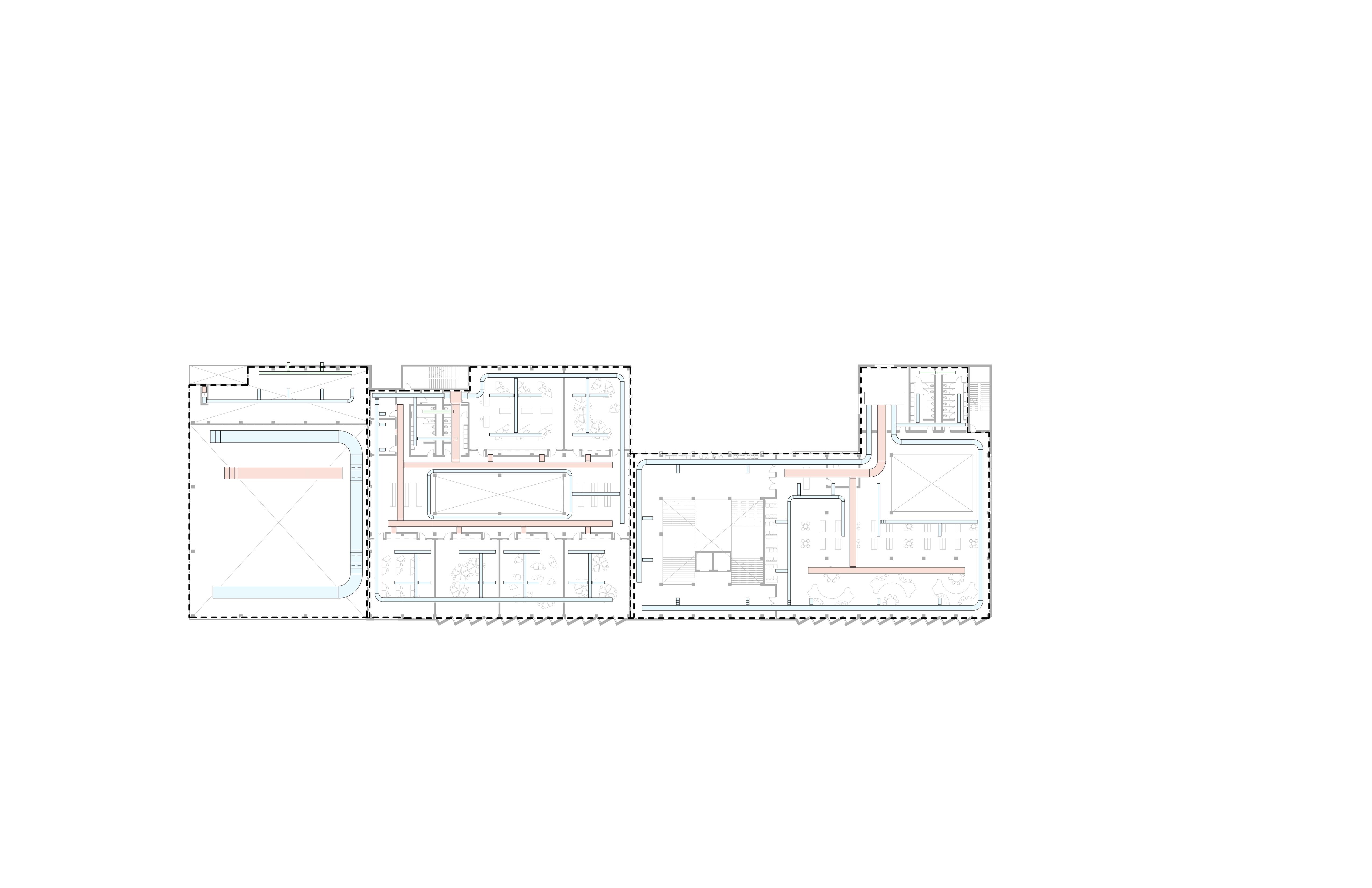
Mech. Shaft
Connects to RTU #2
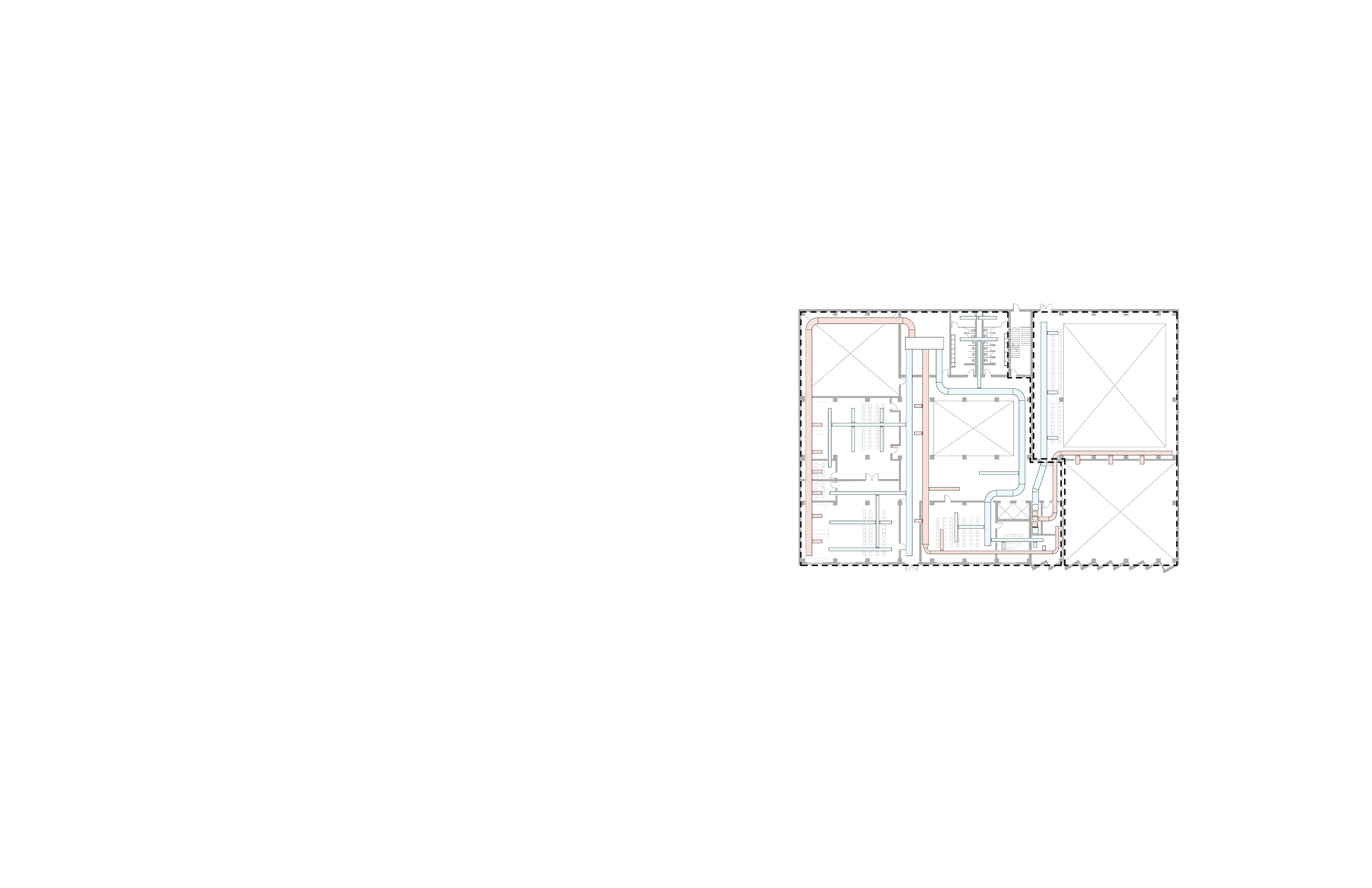
Fresh Air Louvers: 70 ft2 Exhaust Air Louvers: 50 ft2
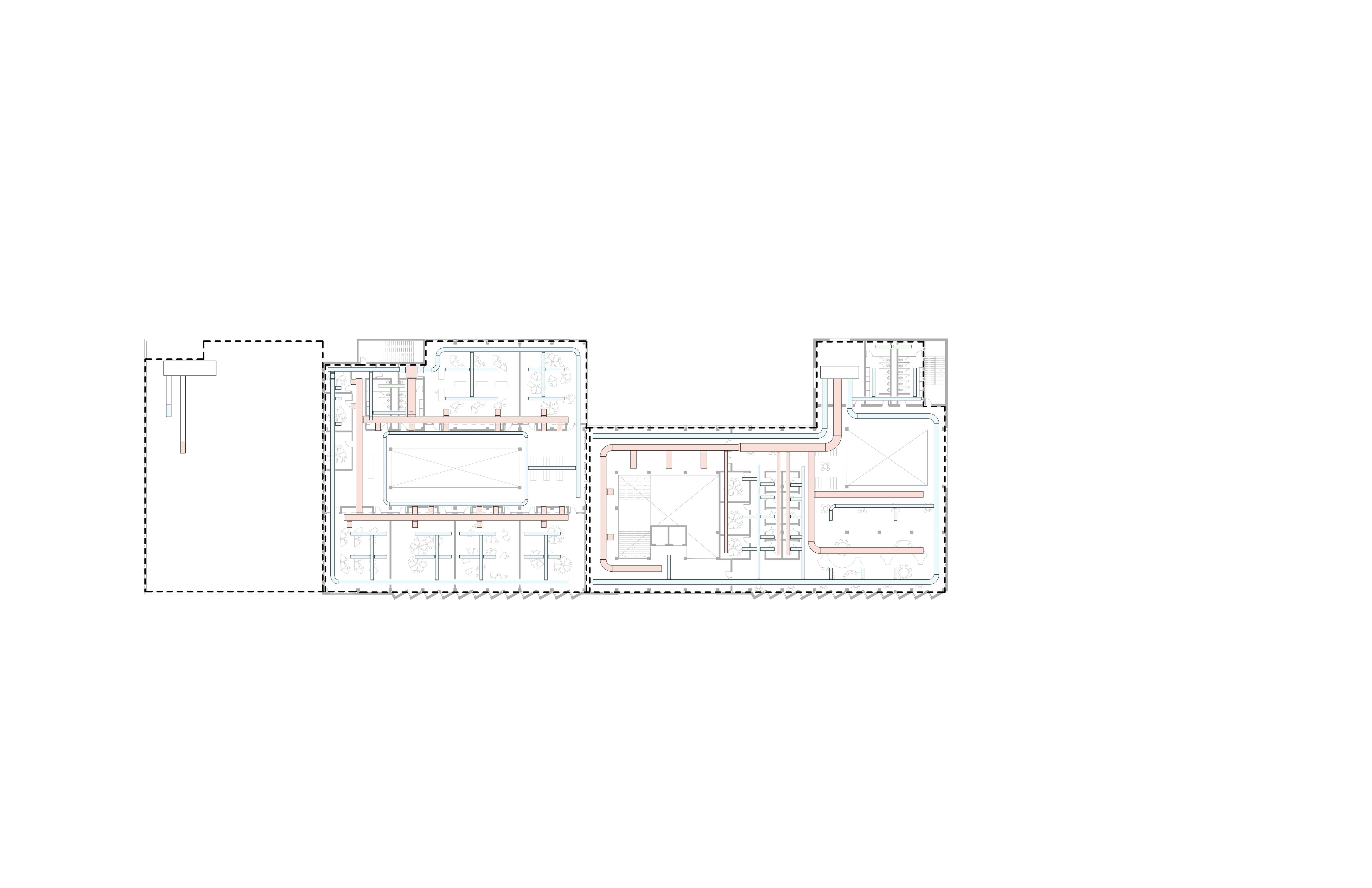
Zone A: Gymnasium
CAV, RTU
12,411 ft2 (includes Levels 1-3)
Main Ducts: 20 ft2
2 Supply: 3’ x 2.5’ (Level 1), 6’ x 2.5’ (Level 3)
2 Return: 1.5’ x 1.5’ (Level 1), 5’ x 3’ (Level 3)
Branch Ducts: 35 ft2
Branch Ducts: 15 ft2 A B C
Zone B: Education
VAV, RTU
45,502 ft2 (includes Levels 1-4)
Main Supply Ducts: 33 ft2
2 Supply: 4’ x 4’
Main Return Duct: 33 ft2
1 Return: 5.5’ x 6’
Branch Ducts: 60 ft2
Zone C: Education
VAV, Fan Room
15,174 ft2 (just Level 3)
Main Supply Ducts: 10 ft2
2 Supply: 2’ x 2.5’
Main Return Duct: 10 ft2
1 Return: 2.5’ x 4’
Zone B: Education
ft2 (includes Levels 1-4)
Zone C: Education