RUB, Inc.

ACTUATION CATALOG
ACTUATORS & VALVES

R
R
RUB, Inc. is the North American headquarter for RUB brass shut-off valves and actuators. Our new facility, built in 2014 in Shakopee, MN, features a 50,000 sq. ft. warehouse with 5-tier racking and state of the art wireless inventory management system controlled by an SAP ERP system.

All brass ball valves are 100% manufactured in Italy at our plant in Brescia. We are a family owned company that has been expanding its global presence and high-quality reputation as a premier ball valve manufacturer for more than 65 years exceeding customer expectations in quality, service and reliability.
Our manufacturing operation is highly automated and every product is tested according to the most rigorous standards, such as our 100% 24-hour dual seal test, and then shipped to RUB, Inc. in Shakopee, MN, USA, to serve the North American markets
We offer forged brass ball valves from 1/8” to 4” in both standard and custom configurations for Oil, Water, Gas, and Industrial applications. We also stock stainless steel ball valves up to 8” and a complete electric and pneumatic actuation line for all of our actuatable brass and stainless-steel products
All standard RUB branded Italian made brass ball valves have a limited lifetime warranty from defects in material and workmanship. For other products, we offer a 2-year limited warranty.
For more information about our complete product offering, certifications, warranties and technical documents, please visit our website at: www.rubinc.com.
Page 2
VALVES & ACTUATORS

R
Page 3

Index • Quality..................................................................................................................................................................................9 • Actuators.............................................................................................................................................................................. • Valves...................................................................................................................................................................................... • RUB, Inc. History.........................................................................................................................................................5 • s.31 NPT Mini Valve.............................................................................................................................38 • s.6439 NPT...............................................................................................................................................40 • s.6439 LT NPT.........................................................................................................................................42 • s.6441 NPT...............................................................................................................................................44 • s.6541 NPT...............................................................................................................................................46 • s.95 NPT.....................................................................................................................................................48 • Puri-T 264 NPT.......................................................................................................................................50 • s.7341 NPT 3-way 4 seats T-port................................................................................................52 • s.7641 NPT 3-way 2 seats L-port (diverting).......................................................................54 • s.134 NPT stainless steel..................................................................................................................56 • s.135 stainless steel............................................................................................................................58 • s.136 stainless steel............................................................................................................................60 • Compact Power...................................................................................................................................11 • C-Tork Electric Actuator - Compact lightweight electric actuator........................12 • CH Electric Actuator - High torque electric actuator..................................................24 • E-Tork Electric Actuator....................................................................................................................30 • EA Pneumatic Actuator...................................................................................................................33 R VALVES & ACTUATORS Page 4
RUB, Inc. History
1993: RUB products enter full force into the North American market with a local warehouse in Massachusetts to support major nationwide distributors to the industrial and commercial plumbing markets.
1994: RUB, Inc. is incorporated as a wholly owned subsidiary in the State of Minnesota setting in place our long-term strategy for RUB valve business in North America.
1997: RUB shifts from using sales agents to hiring direct RUB, Inc. employees.
2000: RUB, Inc. begins sales into Canada.
2006: RUB, Inc. continues to expand its work force including Regional Managers and independent sales rep organizations to lead the sales efforts. The inventory in Massachusetts is transferred to a 17,000-ft² 5 tier racking warehouse in Shakopee, MN, and consigned stock warehouses are established in California and Toronto, Canada.


2008: Pneumatic actuation and stainless-steel ball valves are added to the product offering.
2014: RUB, Inc. builds a new 50,000-ft² office/warehouse in Shakopee, MN, USA, and continues expanding the stainless-steel ball valve offering.


2015: Official Grand Opening of RUB, Inc. North American Headquarters in Shakopee, MN, USA.
2019: RUB, Inc. Quality Management System is certified by LRQA to the standards ISO 9001:2015.

R VALVES & ACTUATORS
Page 5
PAYMENT TERMS
Net 30 days (subject to approval) from invoice date by wire or ACH; checks accepted in some cases. A 1½ % service charge per month will be added to any A/R paid beyond stated term.
FREIGHT POLICY
PPD shipment dependent on total net dollar value of invoice and Freight Zone from RuB Inc. shipping point. All other orders are EXW RuB Inc. Service Warehouse. Contact your RuB Inc. representative for details. PPD shipment based on single destinatio n. RuB Inc. will ship best way unless of specific agreement with customer at time of order concerning timing, special routing instructions, or specific carrier.
ORDER ACCEPTANCE
All orders are subject to acceptance by RuB Inc. List prices, terms and conditions of sale, and products are subject to change without notice. Any item may be modified or discontinued without notice. Minimum acceptable net order value is $250. All orders should be sent to purchaseorder@rubinc.com.
ORDER QUANTITIES
Unless otherwise agreed in writing by RuB Inc., orders must be in multiples of full box quantities as published in the price book. Orders for “broken” box quantities will be invoiced with a non-refundable “broken box” service fee of US $30.00 per line item.
ORDER CANCELLATION
Order cancellations or modifications must reach RuB Inc. in writing and become valid only if acknowledged in writing by RuB Inc. If an order has been placed and staged for delivery, customer must pay 15% restocking fee.
SHORTAGES OR VARIANCE
Claims of shortage or variance due to mis-shipment or damage en route must be reported in writing to RuB Inc. within 5 working days of delivery/receipt of goods. Broken/damaged packages shall be notified in writing immediately to courier’s driver and documented with pictures sent to RuB Inc. along with claim.
RETURNED GOODS
Customer may return material for reasons other than material defect within 6 months of purchase order date. RuB Inc will issue a Return Material Authorization only for goods in marketable condition and in original packaging. Customer will be credited, against future orders, value of returned material less 15% restocking fee, and any applicable freight charges.
PERFORMANCE GUARANTEE
RuB Inc. guarantees to the original purchaser that its original non-modified products will perform at rated capacity as stated in RuB’s catalog only when
(1) properly applied, installed, serviced, and used in accordance with RuB Inc. Installation, Maintenance and Operating Instructions or, if no such instructions are available, prevailing industry standards, as revised from time to time, and
(2) used in environments as specified or as limited by the Installation, Maintenance and Operating Instructions or the RuB catalog.
If RuB Inc. products are part of a greater system, RuB Inc. accepts responsibility only for the products manufactured by it. RuB INC. PRODUCTS MUST BE APPLIED, INSTALLED, SERVICED, AND USED IN ACCORDANCE WITH RuB INC. INSTALLATION, MAINTENANCE AND OPERATING INSTRUCTIONS OR, IF NO SUCH INSTRUCTIONS ARE AVAILABLE, PREVAILING INDUSTRY STANDARDS, as revised from time to time. Failure of the purchaser to apply, install, service and use RuB Inc. products in accordance with relevant instructions or prevailing industry standards, as applicable, will void this performance guarantee.
THE FOREGOING WARRANTY IS EXCLUSIVE AND EXPRESSLY IN LIEU OF ALL OTHER WARRANTIES, EXPRESSED OR IMPLIED AND OF ALL OTHER OBLIGATIONS OR LIABILITIES ON ITS PART, AND IT NEITHER ASSUMES NOR AUTHORIZES ANY OTHER PERSON TO ASSUME FOR IT ANY LIABILITY IN CONNECTION WITH THE SALE OF RuB INC. PRODUCTS. The foregoing warranty is void if the customer fails to apply, install, service and use RuB Inc. products in accordance with relevant instructions or prevailing industry standards, as applicable, or if any modification is made to the warranted products by or for the customer subsequent the dispatch of the products from RuB. The customer indemnifies and holds RuB Inc. harmless from all claims or causes of action arising from any and all customer modifications, even though groundless, as well as from any damage suffered by RuB Inc. arising in whole or in part from such modification. If customer modifies and resells RuB Inc. products, customer agrees to inform end-user that RuB Inc. makes no express or implied warranties regarding such modification(s). The foregoing warranty is also void in the event that product failure results from acts or omissions of persons other than RuB Inc., or from accident or abuse, misuse or misapplication of the products. Most RuB Inc. products are covered by a LIMITED LIFE -TIME WARRANTY to be free of defects in materials and workmanship, with exception of a few products covered for a period of five (5) or two (2) years after date of manufacture. Please refer to the specific product and specific certificate of warranty to see which warranty applies and relevant details and conditions of such warranty.
DISCLAIMER
Except as expressly set forth herein, RuB Inc. makes no representation and extends no warranties of any kind, either expre ss or implied, including any warranties of quality, merchantability, title, or fitness for any particular purpose, whether alleged to arise by law, by reason of custom or usage in the trade, or by course of dealing.
LIMITATIONS OF LIABILITY
In no event shall RuB Inc., or its affiliates, officers, directors, employees, agents or attorneys, be liable for any CONSEQUENTIAL, INCIDENTAL, PUNITIVE, OR SPECIAL DAMAGES ARISING OUT OF OR CONNECTED WITH THE PURCHASE OF RuB INC. PRODUCTS regardless of liability, breach of warranties, failure of essential purpose or otherwise, even if advised of the possibility of such damages.
AGREEMENT OF SALE
No agreement of sale shall be in effect until RuB Inc. forwards to the customer an invoice detailing the customer’s purchase of RuB Inc. products. Any agreement of sale hereunder shall be deemed to take place in the State of Minnesota ( RuB Inc. headquarters) and shall be subject to the terms and conditions of sales set forth herein. These terms and conditions shall supersede any and all terms and conditions of sale of any customer purchase order. In case of discrepancy between any term in this document and the quote, the latter shall prevail. Unless otherwise stated, any undated reference to a code or standard shall be interp reted as referring to the latest edition.
GOVERNING LAW
The terms and conditions of sale set forth herein shall be governed by, and construed and enforced in accordance with the laws of the State of Minnesota (without regard to conflicts of law principles for such state). Each customer, by entering into an agreement of sale hereunder, irrevocably and unconditionally consents to submit to the exclusive jurisdiction of the courts of the State of Minnesota and of the United States of America, for any claim ari sing out of or relating in any manner (whether in contract, tort or otherwise) to such agreement of sale (and agrees not to commence any claim relating thereto except in such courts).
POTABLE WATER BRASS VALVES
For LOCALITIES that require “LEAD FREE” (0.25% or less Pb) brass valves for potable water applications, RuB Inc. offers specific models certified to NSF/ ANSI 61-G and/ or NSF/ANSI 372. These products are identified as such on the handle. RuB Inc. PRODUCTS, WHICH ARE NOT IDENTIFIED AS COMPLIANT WITH ABOVE SPECIFICATIONS ARE NOT TO BE USED IN DRINKING WATER SYSTEMS. RuB Inc. cannot accept responsibility for mis-application of PRODUCTS TO DRINKING WATER SYSTEMS.
CALIFORNIA PROPOSITION 65

FOR BRASS VALVES SOLD IN CALIFORNIA: WARNING: Brass valves can expose you to chemicals including lead which are known to the state of California to cause cancer and birth defects or other reproductive harms. For more information: www.P65Warnings.ca.gov.
MAJOR FORCE
In no event shall RuB Inc. be responsible or liable for any failure or delay in performance of its obligation arising out of or caused, directly or indirectly, by circumstances beyond its reasonable control, including, without limitation: explosions, floods, fires, storms or earthquakes, epidemics, pandemics, war or threat of war, sabotage, insurrection, shortage of raw materials, refusal or impediment of any authority to issue any license or authorization for import and export, strikes or lab or disputes, prohibitions and other events that in any way prevent RuB Inc. from purchasing or importing raw materials and / or components or the production, transport or export of the Products. I n such cases, customer will have the possibility to cancel the open orders, if the cause of force majeure continues for a period of more than six months, without any other right to claim any co mpensations or damages.
Page 6
MOD.04.000.09USA.Rev. 5 24-06-2021 RuB Inc.TERMS & CONDITIONS OF SALES

Page 7
Quality you can Trust proven through generations of experience

R VALVES & ACTUATORS Page 8
Page 10
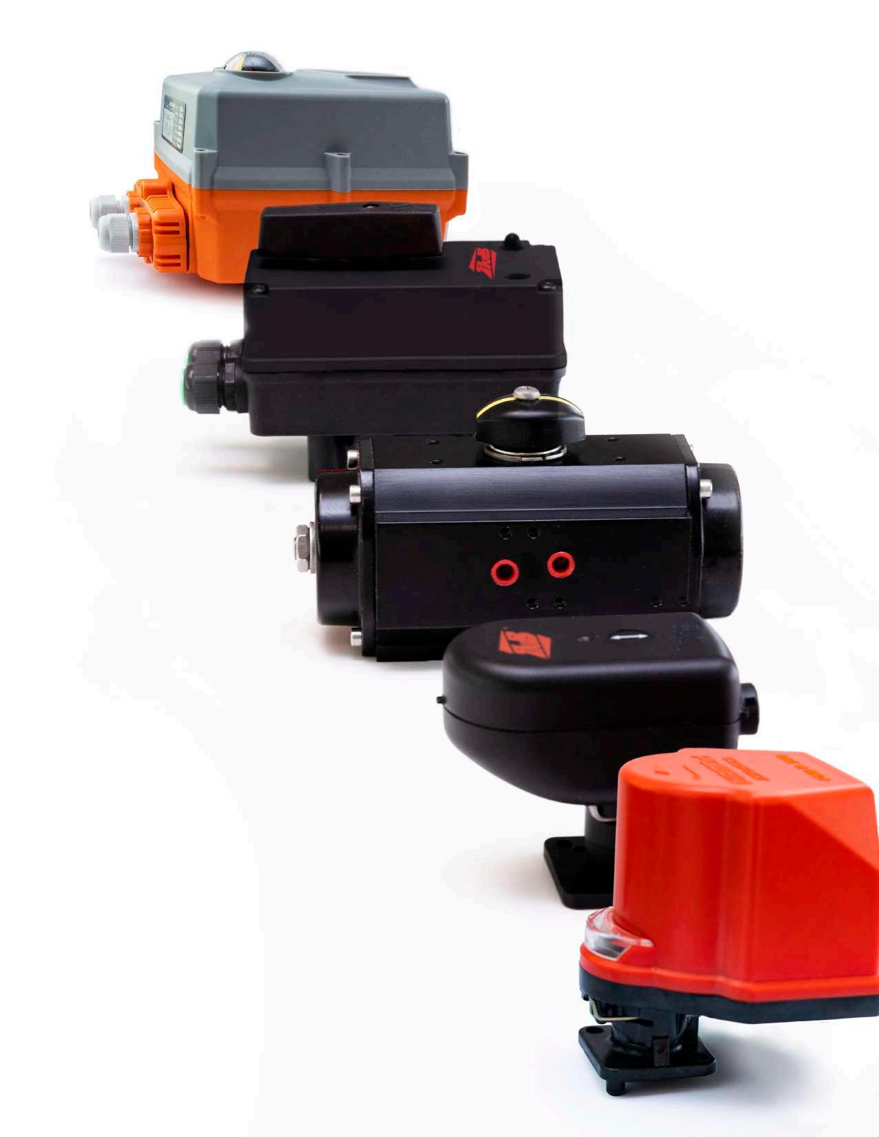
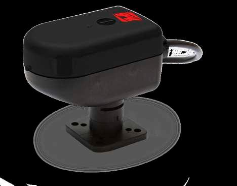
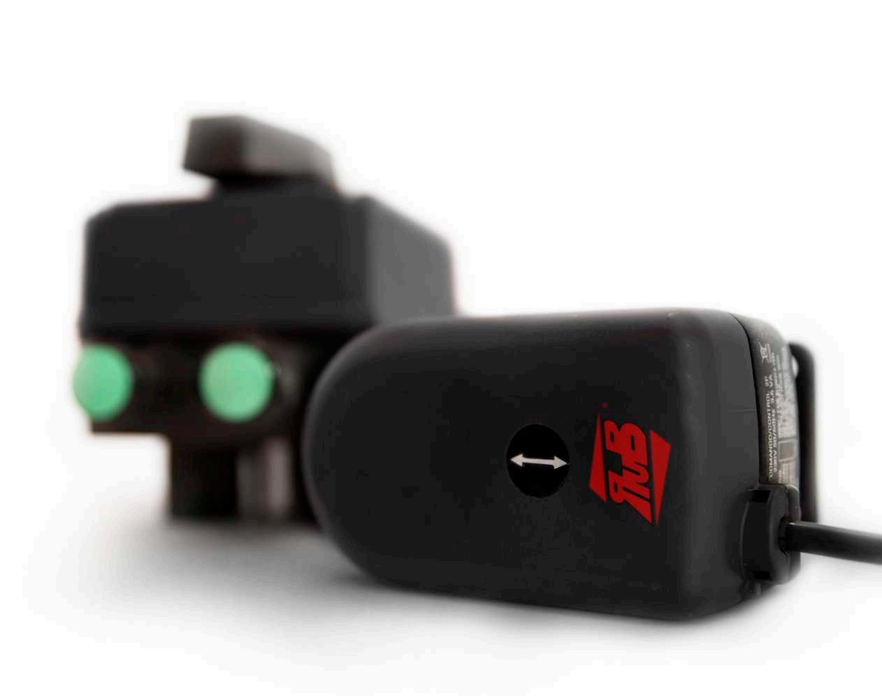
electric actuator
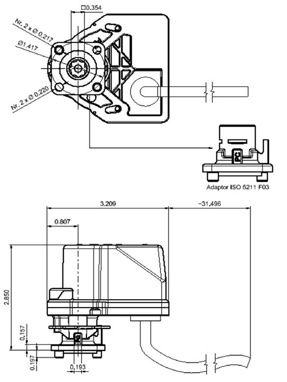
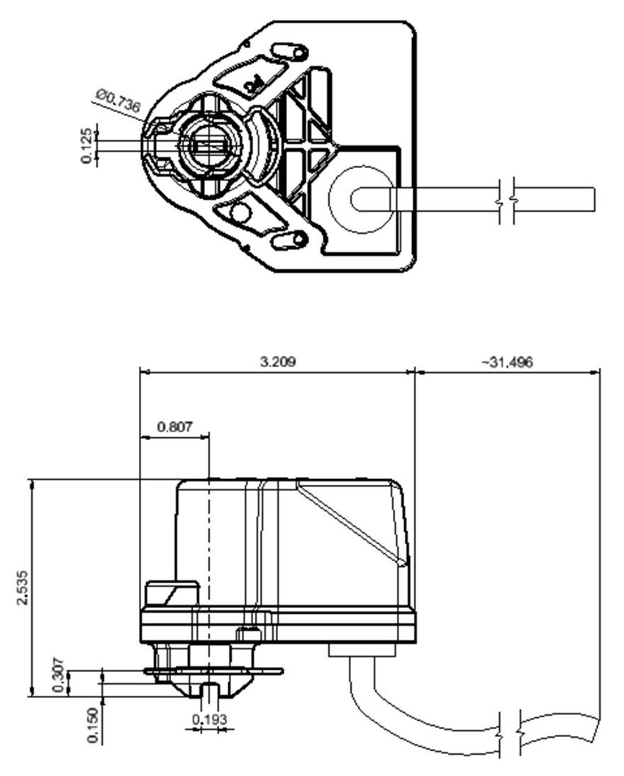
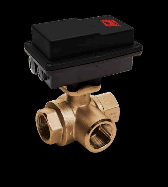
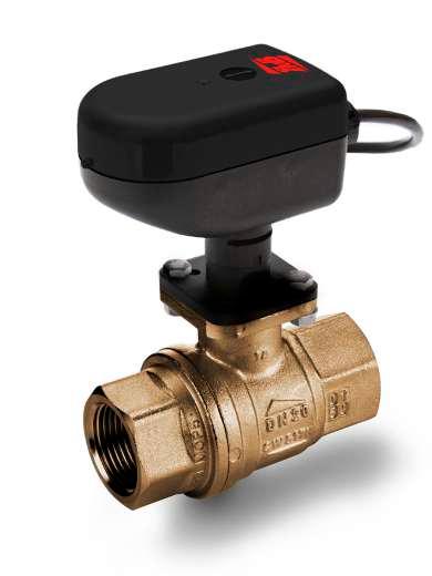
The CP series Electric actuator provide an output torque of 44 inch-pound and it’s available in AC and DC voltage. They have a small footprint directly mounted on valves and they enable installation in confined spaces.
Technical features:
• Suitable for RUB actuatable valves up to 1 1/4” size (only for s.64 LT, s.65 and s.76 up to 1")
• Compact package to fit in restricted spaces
• Motor power consumption:
- 4W for 24V DC, 6W for 230V AC
- 8W for 24V AC and 110-120V AC
• Torque output up to 44 in-lb
• Operation time:
- 5sec for 12 V DC, 24V DC
- 15 sec for 24V AC, 110-120 V AC and 230 V AC at 60Hz
• Working temperature -4°F +180°F
• Protection class IP65 comparable to NEMA 4X

Options:
• Power supply:
- 12 V DC, 24V DC
- 110-120V AC 50/60Hz
- 230V AC 50/60Hz
- 24V AC 50/60Hz
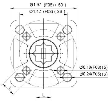
• Adaptor F03 square 0.354 inch
• Micro-switches for open-close signals
• Micro-switches can pass up to 1A
• Reversing motor
• Direct mount on valve for perfect shaft alignment
• Positive orientation between ball valve and actuator
• Actuator easily removable for manual operating
• Visual position indicator
• Corrosion resistant plastic housing
• Actuator has successfully passed 100,000 cycle life tests
• Duty cycle 60%
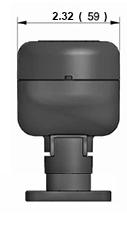
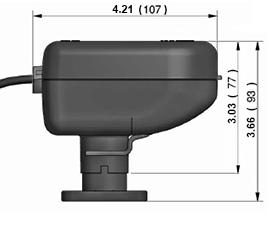
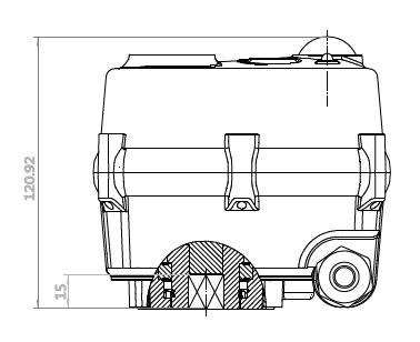
Dimensions inches
Page 11 R ALVES & ACTUATORS
Model Torque (In/LB) Seconds 90° Power CP5A2 44 15s 230V AC, 2 wires CP5A3 44 15s 230V AC, 3 wires CP5B2 44 15s 110V AC, 2 wires CP5B3 44 15s 110V AC, 3 wires CP5C2 44 15s 24 V AC, 2 wires CP5C3 44 15s 24 V AC, 3 wires CP5D2A 44 5s 24 V DC, 2 wires CP5E2A 44 5s 12 V DC, 2 wires
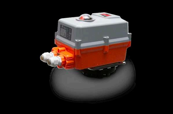
C-Tork Actuator
Compact lightweight electric actuator
The CT electric actuators are designed to drive ball and butterfly valves with ISO5211 mounting pad, providing a quarter turn motion. In combination with RUB valves are used in wastewater treatment plants, power plants, refineries, mining processes, food factories and in the fluid automated control in HVAC.
The CT family provides the following output torques:
CT1 70.8 lb-in (8 Nm)
CT2 97.3 lb-in (11 Nm)
CT3 194.7 lb-in (22 Nm)
CT4 354 lb-in (40 Nm)
Technical features & benefits:
• Direct ISO 5211 mount on valves. Requires no separate linkage because the CT Series Actuators are ready for direct attachment to ISO5211 mounting pad.
• Compact package with perfect shaft alignment. Smaller actuator footprint enables installation in confined spaces; direct mount on ball valves reduces the mounting space requirement.
• Several voltage ratings available. Available with the most common power supplies around the globe.
• Fire retardant plastic with high IP ratings enclosure. Provides a high degree of protection from dust, splashing water, rough handling and tough environments.
• Auxiliary Switches.
Provides line voltage capable switch up to 1 A Resistive.
• Special models available. The CT family fits the customer needs extending the application coverage on request.

Page 12 R VALVES & ACTUATORS
Model Nominal Torque
Key Codes:
Option:
Auxiliary Switches:
Manual Override:
R = Anti-condensation Resistance
FO = Failsafe Valve Open
FC = Failsafe Valve Close
0 = No Micro
1 = 1 Aux. Switch
2 = 2 Aux. Switches
M = Manual Override
N = No Manual
A = 2 wires
B = 3 wires
C = 2 and 3 wires
Control Type:
D = Prop. 0 - 10 Vdc
E = Prop. 2 - 10 Vdc
F = Prop. 0 - 20 mA
G = Prop. 4 - 20 mA
A = 230Vac 50/60 Hz *
B = 110Vac 50/60 Hz *
C = 24Vac 50/60 Hz *
D = 24Vdc
Power Supply:
E = 12Vdc
F = 24Vac/dc
G = 48 - 240Vac
H = 230Vac 60 Hz **
I = 110Vac 60Hz **
L = 24Vac 60Hz **
CT1 = 70.8 lb-in (8Nm)
CT2 = 97.3 lb-in (11Nm)
Note: * Not valid for CT4 (50 Hz only), ** Valid for CT4 only
Model:
CT3 = 194.7 lb-in (22Nm)
CT4 = 354 lb-in (40Nm)
Ask for additional information on the whole range of RUB, Inc. products and consult with your supplier for special applications.
Page 13 R VALVES & ACTUATORS
CT X X X X X X
CT1 - 70.8 lb-in
Ordering Codes
Optional models on request:
• 44.2 lb-in with 15 sec running time, Vac only
• Vdc 2/3 wires 30 sec running time
• 12 Vdc power supply, 2/3 wires 60 secs running time
Dimensions inches (mm)
• Different Input signal on modulating: 0(2)-10 Vdc, 0(4)-20 mA
• Modbus Communication
• On/Off 3 positions (0°, 45° and 90°)
Page 14 R VALVES & ACTUATORS
Code Power supply Control Type Running time (0°-90°) Feedback type CT1AAN1 230 Vac 50/60 Hz 2 wires 45 sec @ 50Hz 1 microswitch & 1 output phase 38 sec @ 60Hz CT1BAN1 110 Vac 50/60 Hz 2 wires 45 sec @ 50Hz 38 sec @ 60Hz CT1CAN1 24 Vac 50/60 Hz 2 wires 45 sec @ 50Hz 38 sec @ 60Hz CT1ABN1 230 Vac 50/60 Hz 3 wires 35 sec @ 50Hz 30 sec @ 60Hz CT1BBN1 110 Vac 50/60 Hz 3 wires 35 sec @ 50Hz 30 sec @ 60Hz CT1CBN1 24 Vac 50/60 Hz 3 wires 35 sec @ 50Hz 30 sec @ 60Hz CT1DCN0 24V DC 2/3 wires 60 sec. 2 output phases CT1FDN0 24V DC / AC ± 20% 50/60 Hz Modulating 0-10Vdc 60 sec. 2 -10 Vdc
ISO 5211 L F03 0.35 with adapter (9) F05 0.43 (11) (8 Nm)
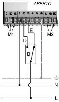
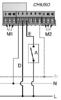
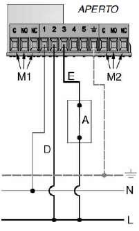
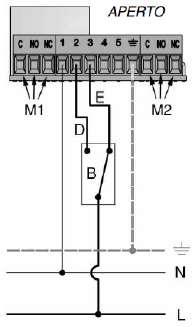
Wiring diagrams
Vac models 2 wires control
Vac models 3 wires control
Vdc models 2 wires control
Vdc models 3 wires control
Proportional models
41°F to 122°F (+5 °C to +50°C)
Degree of protection IP 54 (Equivalent to NEMA3)
Insulation class II - double insulation
Outer shell material
Polyamide PA 6 - 30% glass fibers
24V AC 0-10V DC / 2-10V DC 2-10V DC Positioning signal Feedback signal 0-20 mA / 4-20V mA 24V DC OPEN POSITION OPEN POSITION CLOSE POSITION CLOSE POSITION OPEN N BLUE BROWN (CLOSE) GREEN (OPEN) GREY WHITE PINK TA L M1 OPEN N BLUE BROWN (CLOSE) GREEN (OPEN) GREY WHITE PINK TA L M1 CLOSED N BLUE BROWN (CLOSE) GREEN (OPEN) GREY WHITE PINK TA L M1 CLOSED N BLUE BROWN (CLOSE) GREEN (OPEN) GREY WHITE PINK TA L M1 Page 15 R VALVES & ACTUATORS
specification 2 wires Vac 3 wires Vac 2/3 wires Vdc Modulating Position indicator Rotating arrow, indicating the position of the sphere Power supply 230 V - 50/60 Hz 24Vdc 24V DC / AC ± 20% 50/60 Hz 24 V - 50/60 Hz 12Vdc 110 V - 50/60 Hz Power cable length 31.5 inches (80 cm) (other sizes on request) Operating time (90°) 45 sec @ 50Hz 38 sec @ 60Hz 35 sec @ 50Hz 30 sec @ 60Hz 60 sec 60 sec Absorbed power 3.9 VA 2 VA 3.5 W Electrical capacity of the additional microswitch 1 A resistive - 250V Not available Maximum noise (1 meter away) 40 dB (A) Operating ambient temperature
Technical
Certification CE
BLUE BROWN (CLOSE) GREEN (OPEN) WHITE PINK EXIT PHASE C ( - ) (+) (+) BLUE BROWN (CLOSE) GREEN (OPEN) WHITE PINK EXIT PHASE C ( - ) (+) (+) RED BLACK GREEN WHITE PINK YELLOW + ~ T + +-BLUE BROWN (CLOSE) GREEN (OPEN) WHITE PINK EXIT PHASE C ( - ) (+) (+) BLUE BROWN (CLOSE) GREEN (OPEN) WHITE PINK EXIT PHASE C ( - ) (+) (+)
CT2 - 97.3 lb-in
Ordering Codes
Optional models on request:
• 12 Vdc power supply
• Optional speed:
- Vac only : 12 sec or 4 sec (44.2 lb-in)
- Vdc only : 8 sec and 5 sec (97.3 lb-in); 3 sec (70.8 lb-in); 1 sec (44.2 lb-in)
Dimensions inches (mm)
Vac models
• Proportional models: 0(2)-10 Vdc, 0(4)-20 mA, Modbus
• Electronic fail safe (see page 22)
Vdc models ISO 5211 L
F03 0.35 with adapter (9)
F05 0.43 (11)
Page 16 R VALVES & ACTUATORS
Code Power supply Control Type Running time (0°-90°) Feedback type CT2ACM2 230 Vac - 50/60 Hz 2/3 wires 35 sec @ 50Hz 30 sec @ 60Hz 2 x Free auxiliary switches CT2BCM2 110 Vac - 50/60 Hz 2/3 wires 35 sec @ 50Hz 30 sec @ 60Hz CT2CCM2 24 Vac - 50/60 Hz 2/3 wires 35 sec @ 50Hz 30 sec @ 60Hz CT2DCN2 24V DC 2/3 wires 12 sec.
(11 Nm)
Wiring diagrams

2 wires control
3
Vac
Auxiliary switches
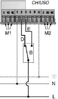
CLOSED CLOSED OPEN OPEN Page 17 R VALVES & ACTUATORS
wires control
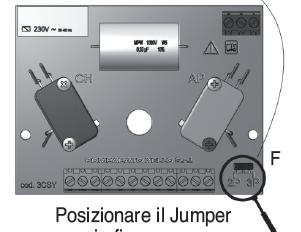
the jumper
the
electrical connection.
models: Move
to have
desired
jumper change is
C VALVE OPEN
(additional opening microswitch)
(additional closing microswitch) VALVE CLOSED VALVE NOT OPEN VALVE NOT CLOSED C C C NC NC NC NC NO NO NO NO Technical specification ALL IN ONE - 2/3 wires Vac ALL IN ONE - 2/3 wires Vdc Position indicator and manual override Manual lever with arrow indicating the position of the sphere Not available Power supply 230 V - 50/60 Hz 24Vdc 110 V - 50/60 Hz 12Vdc 24 V - 50/60 Hz Electric connections Via terminal board inside the actuator Operating time (90°) 35 sec @ 50Hz 30 sec @ 60Hz 12 sec Absorbed power 6 VA (230 V) 0.3A (24Vdc) 6 VA (110 V) 7.5 VA (24 V) 0.5A (12 Vdc) Maximum current supported by the additional microswitches 1 A resistive Not available Maximum noise (1 meter away) 35 dB (A) standard version 47 dB (A) standard version Operating ambient temperature 14°F to 122°F (-10 °C to +50°C) Degree of protection IP 67 (Equivalent to NEMA6) Outer casing Characterized by a ribbed shape made of glass-filled "polyarylamide" technopolymer, particularly robust and impermeable to humidity Certification CE
Vdc models: No
needed
M1
M2
CT3 - 194.7 lb-in
Ordering Codes
Optional models on request:
• 12 Vdc power supply
• Optional speed: - Vac only : 9 sec - Vdc only: 10 sec
• Proportional models: 0(2)-10 Vdc, 0(4)-20 mA, Modbus
• Electronic fail safe (see page 22)
Vac models
Vdc models
Dimensions inches (mm) ISO 5211 L F03 0.35 with adapter (9)
0.43 (11)
Page 18 R VALVES & ACTUATORS
Code Power supply Control Type Running time (0°-90°) Feedback type CT3ACM2 230 Vac - 50/60 Hz 2/3 wires 45 sec @ 50Hz 38 sec @ 60Hz 2 x Free auxiliary switches CT3BCM2 110 Vac - 50/60 Hz 2/3 wires 45 sec @ 50Hz 38 sec @ 60Hz CT3CCM2 24 Vac - 50/60 Hz 2/3 wires 45 sec @ 50Hz 38 sec @ 60Hz CT3DCN2 24V DC 2/3 wires 30 sec.
(22 Nm)
F05
Wiring diagrams
2
Technical specification
Vac models: Move the jumper to have the desired electrical connection. Vdc models: No jumper change is needed
Outer casing
Characterized by a ribbed shape made of glass-filled "polyarylamide" technopolymer, particularly robust and impermeable to humidity
Page 19 R VALVES & ACTUATORS
ALL IN ONE - 2/3 wires Vac ALL IN ONE - 2/3 wires Vdc Position indicator and manual override Manual lever with arrow indicating the position of the sphere Not available Power supply 230 V - 50/60 Hz 24Vdc 110 V - 50/60 Hz 12Vdc 24 V - 50/60 Hz Electric connections Via terminal board inside the actuator Operating time (90°) 45 sec 30 sec Absorbed power 5 VA (230 V) 0.25 A (24Vdc) 5 VA (110 V) 6 VA (24 V) 0.4 A (12 Vdc)
current supported by the additional microswitches 1 A resistive Maximum noise (1 meter away) 42 dB (A) standard version 52 dB (A) standard version Operating ambient temperature 14°F to 122°F (-10 °C to +50°C)
of protection IP 67 (Equivalent to NEMA6)
Maximum
Degree
Certification CE
control
C VALVE OPEN
(additional opening microswitch) M2 (additional closing microswitch) VALVE CLOSED VALVE NOT OPEN VALVE NOT CLOSED C C C NC NC NC NC NO NO NO NO CLOSED CLOSED OPEN OPEN
wires control 3 wires
Auxiliary switches
M1
CT4 - 354 lb-in
Ordering Codes
Optional models on request:
• 24Vdc and 12 Vdc power supply
• Optional speed: - Vac only : 14 sec and 32 sec
Dimensions inches (mm)
Vac models
• Proportional models: 0(2)-10 Vdc, 0(4)-20 mA, Modbus
• Electronic fail safe (see page 22)
Page 20 R VALVES & ACTUATORS
Code Power supply Control Type Running time (0°-90°) Feedback type CT4ACM2 230 Vac 50 Hz 2/3 wires 55 sec. 2 x Free auxiliary switches CT4BCM2 110 Vac 50 Hz 2/3 wires 55 sec. CT4CCM2 24 Vac 50 Hz 2/3 wires 55 sec. CT4HCM2 230 Vac 60Hz 2/3 wires 45 sec. CT4ICM2 110 Vac 60Hz 2/3 wires 45 sec. CT4LCM2 24 Vac 60Hz 2/3 wires 45 sec.
ISO 5211 L F05 0.43 with adapter (11) F07 0.55 (14) (40 Nm)
Wiring diagrams
2 wires control
3 wires control
Technical specification
Vac models: Move the jumper to have the desired electrical connection.
Auxiliary switches
M1 (additional opening microswitch)
M2 (additional closing microswitch)
ALL IN ONE -
Position indicator and manual override Manual lever with arrow indicating the position of the sphere
Power supply
Electric connections
Operating time (90°)
Maximum absorbed power (standard version 55sec)
Maximum current on the output phase at terminals 4 and 5
Maximum current supported by the additional microswitches
230 V - 50 Hz
110 V - 50 Hz
24 V - 50 Hz
Via terminal board inside the actuator
55 sec @ 50Hz
45 sec @ 60 Hz
13 VA (230 V)
11 VA (110 V)
12 VA (24 V)
1 A resistive
1 A resistive
Maximum noise (1 meter away) 50 dB (A) standard version
ambient
Degree of protection
Outer casing
Characterized by a ribbed shape made of glass-filled "polyarylamide" technopolymer, particularly robust and impermeable to humidity
Page 21 R
& ACTUATORS
VALVES
VALVE OPEN
C
VALVE CLOSED VALVE NOT OPEN VALVE NOT CLOSED C C C NC NC NC NC NO NO NO NO CLOSED CLOSED OPEN OPEN
2/3 wires
122°F (-10
Operating
temperature 14°F to
°C to +50°C)
IP 67 (Equivalent to NEMA6)
Certification CE
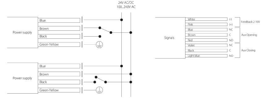
Super capacitors electronic Fail Safe actuators
Using the SuperCaps technology the CT2, CT3 and CT4 actuators can store the necessary energy to drive open or close the valve in a safety position during an electrical power supply interruption. Fail safe open or close position in valves is crucial to prevent serious damages in critical applications such as coils freezing or steam exchangers overpressure. By default they are all provided with a 2-10 Vdc feedback, two auxiliary switches and 1m cable lenght.
Ordering Codes
Note: X=O for Fail safe valve open; C for Fail Safe valve close X
Technical specification - Fail safe Models
Wiring diagrams
On/Off models
3 wires control
2 wires control
Proportional models
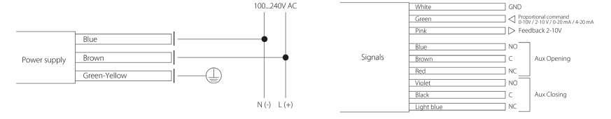
CT2 CT3 CT4 Available power supply 24Vdc - 24V 50/60 Hz - 100...240V 50/60Hz Max. Running power consumption 10W 25W 25W Power supply cable 40 in. (1 m) length AWG20 Signal cable 40 in. (1 m) length AWG24 Auxiliary switches rating max 30V DC - 0.1 A max 30V DC - 0.1 A max 30V DC - 0.1 A Nominal Torque 97.3 lb-in 194.7 lb-in 354 lb-in Available control type On/off 2&3 wires - proportional Valve position feedback 2 -10V DC Manual Override Manual lever with arrow indicating the position of the sphere Running Speed (90°) 30s Fail safe speed(90°) 20 s 26 s 30 s Max Noise 45 dB (A) 60 dB (A) 65 dB (A) Degree of protection IP67 SuperCaps recharging time 15 min (90°) 15 min (90°) 50 min (90°) Operating ambient temperature 14°F to 122°F (-10°C to 50°C) Certification CE Page 22 R VALVES & ACTUATORS
Code Torque (in/lb) Power supply CT2FCM2Fx 97.4 24Vdc - 24V 50/60 Hz CT2GCM2Fx 97.4 100...240V 50/60 Hz CT3FCM2Fx 194.7 24Vdc - 24V 50/60 Hz CT3GCM2Fx 194.7 100...240V 50/60 Hz CT4FCM2Fx 354 24Vdc - 24V 50/60 Hz CT4GCM2Fx 354 100...240V 50/60 Hz
Page 23 R VALVES & ACTUATORS
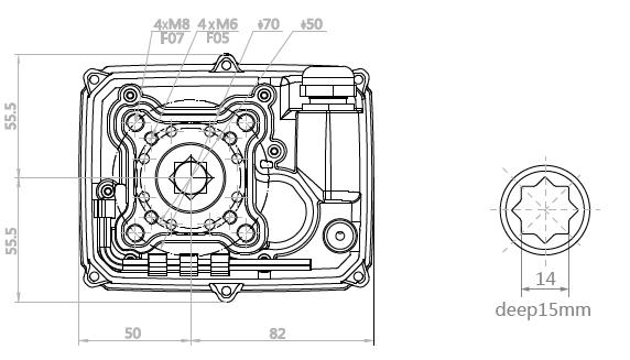
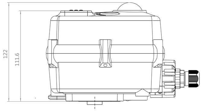
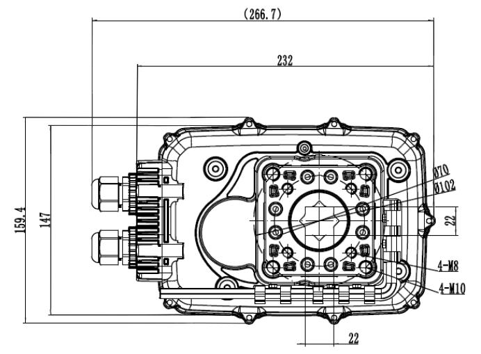
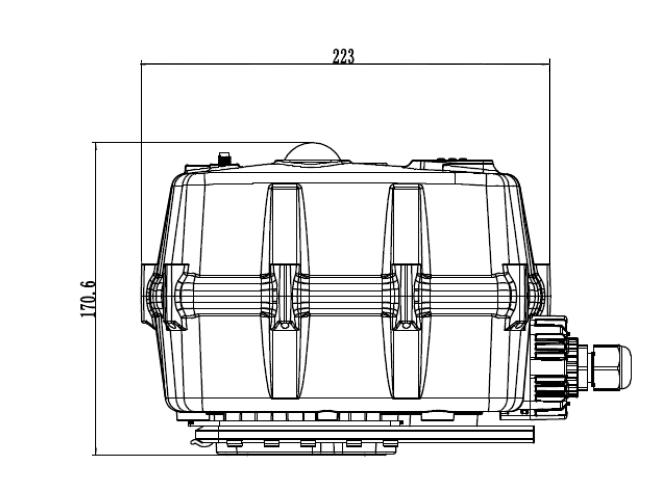
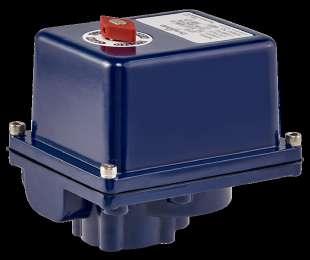
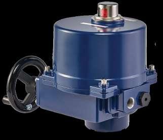
CH Actuator
High Torque electric actuator
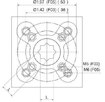
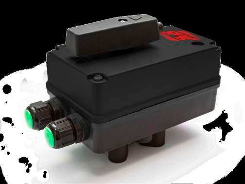
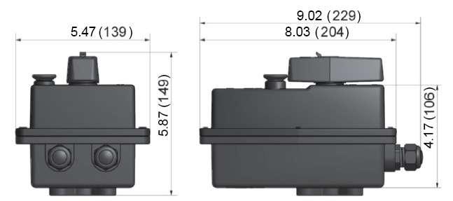
The CH valve actuators are used on ball or butterfly valves. This quarter turn actuators are available from 443 lb-in to 3540 lb-in As standard, this actuator offers an IP67 ABS housing, dome position indicator, end of travel limit switches, manual override and an internal heater. The new Series offers multi-voltage capability and failsafe functionality utilizing a super-capacitor back-up system.
The CH family provides the following output running torques:
CH1 443 lb-in (50 Nm)
CH2 708 lb-in (80 Nm)
CH3 974 lb-in (110 Nm)
CH4 1770 lb-in (200 Nm)
CH5 3540 lb-in (400 Nm)
Technical features & benefits:
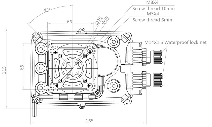
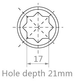
• Multiple ISO 5211 mountings. The CH Series Actuators are ready for direct attachment on valves providing two size ISO 5211 and an octagonal female drive output.
• Dome style local visual indicator. A clearly visible indicator allows intuitive indication of the valve position.
• Hand operation. by hexagonal wrench,supplied in clip under the actuator, it’s possible to do open/close operation when no power is being applied.
• Fully weatherproof to IP67. Enhances the range of application environments.
• End of travel confirmation switches. Provides line voltage capable switch up to 1 A Resistive.
• Special models available. The CH family fits the customer needs extending the application coverage on request.
Page 24 R VALVES & ACTUATORS
Model Nominal Torque
Wiring diagrams - On/Off models
2 wires M ON Blue Red Black Whit e Gray Brow n Yellow/Green OFF N L Feedback_Com Feedback_Ope n Feedback_Close SW 1 2 3 9 7 8 5 Contro l Driver 3 wires M ON Blue Red Black Whit e Gray Brow n Yellow/Green OFF VV+ Feedback_Com Feedback_Open Feedback_Clos e SW 1 2 3 9 7 8 5 Contro l Driver
CH1 - 443 lb-in (50
Technical specification
Nm)
Yes, by hexagonal wrench (supplied in clip) when no power is being applied.
Not continuous, allow ≥ 1 minute between cycles

Mechanically driven dome style visual 2 colour indicator Mounting
Do not install underslung/upside down. Can install upright horizontally or vertically. End position
Micro-switches operated by adjustable internal cams , set slightly ahead of the final motor stop position.
F05 & F07
Factory set at 90° ± 2°, maximum angle of rotation 360° unless multi turn series.
0.55 inch x 0.59 inch deep
*Note: x = O Failsafe Valve Open; C Failsafe Valve Closed
inches
Page 25 R VALVES & ACTUATORS
ON-OFF ELECTRIC ACTUATOR ON-OFF FAILSAFE ELECTRIC ACTUATOR Ordering code CH1GCM2 CH1FCM2 CH1GCM2Fx* CH1GCM2Fx* Rated voltage 95-265VAC/DC (50/60Hz) 24VAC/DC (50/60Hz) 95-265VAC/DC (50/60Hz) 24VAC/DC (50/60Hz) Voltage range AC: 95-265V DC: 100-300V AC: 18-26V DC: 22-28V AC: 95-265V DC: 100-300V AC: 18-26V DC: 22-28V Consumption 25 W 25 W 40 W 40 W Peak current 6.25 A 6.25 A 6.25 A 6.25 A Fuse 2 A 4 A 4 A 4 A Maximum break Torque lb-in 531.04 lb-in 531.04 lb-in Manual operation
Run time ≈
Operating
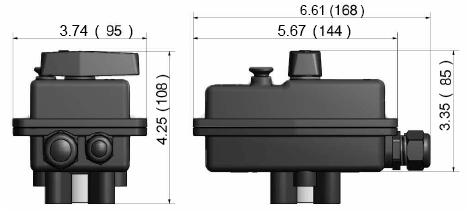
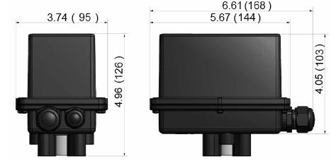
Dimensions
10 sec
frequency
Position confirmation
restriction
indication
ISO
Working angle
5211
Female drive
Ingress protection IP67 Max media temperature ≤ 176° F Ambient temperature -4° F to 140° F Non-operating temperature -40° F to 176° F Ambient humidity 5-95% RH non-condensing Housing
(ABS)
Plastic
cover
2.19 2.19 1.97 Ø1.97 Ø2.76 3.23 0.55 deep 0.59 inch 4.76 0.59
CH2 - 708 lb-in (80 Nm)
Technical specification
Not continuous, allow ≥ 1 minute between cycles
Mechanically driven dome style visual 2 colour indicator
Do not install underslung/upside down. Can install upright horizontally or vertically.
Micro-switches operated by adjustable internal cams , set slightly ahead of the final motor stop position.
Factory set at 90° ± 2°, maximum angle of rotation 360° unless multi turn series.
*Note: x=O Failsafe Valve Open; C Failsafe Valve Closed
Page 26 R VALVES &
ACTUATORS
Dimensions
ON-OFF ELECTRIC ACTUATOR ON-OFF FAILSAFE ELECTRIC ACTUATOR Ordering code CH2GCM2 CH2FCM2 CH2GCM2Fx* CH2FCM2Fx* Rated voltage 95-265VAC/DC (50/60Hz) 24VAC/DC (50/60Hz) 95-265VAC/DC (50/60Hz) 24VAC/DC (50/60Hz) Voltage range AC: 95-265V DC: 100-300V AC: 18-26V DC: 22-28V AC: 95-265V DC: 100-300V AC: 18-26V DC: 22-28V Consumption 60 W 60 W 60 W 60 W Peak current 3.75 A 3.75 A 3.75 A 3.75 A Fuse 4 A 4 A 4 A 4 A Maximum break Torque lb-in 796.57 lb-in 796.57 lb-in 796.57 lb-in 796.57 lb-in Manual operation Yes,
applied. Run time ≈ 10 sec Operating frequency
inches
by hexagonal wrench (supplied in clip) when no power is being
Position confirmation
restriction
End position indication
ISO 5211 F05
Working angle
Female drive 0.67 inch
Ingress protection IP67 Max media temperature ≤ 176° F Ambient temperature -4° F to 140° F Non-operating temperature -40° F to 176° F Ambient humidity 5-95% RH non-condensing Housing Plastic (ABS)
Mounting
& F07
x 0.83 inch deep
cover
4.80 4.39 4.53 2.60 6.50 0.67 Screw thread 0.39 inch Screw thread 0.24 inch Hole depth 0.83 inch 6.50 Ø2.76Ø1.97
CH3 - 974 lb-in (110 Nm)
Technical specification
Yes, by hexagonal wrench (supplied in clip) when no power is being applied
AC not continuous, 75% duty cycle but recommend allowing ≥1 min between cycles. DC is continuous.
Mechanically driven dome style visual 2 color indicator
None, it can be mounted at any angle. Leave space for manual operation and electrical connection.
Micro-switches operated by adjustable internal cams , set slightly ahead of the final motor stop position.
F05 & F07
Factory set at 90° ± 2°
inch octagon x 0.83 inch deep
*Note: x=O Failsafe Valve Open; C Failsafe Valve Closed
inches
Page 27 R VALVES & ACTUATORS
Dimensions
ON-OFF ELECTRIC ACTUATOR ON-OFF FAILSAFE ELECTRIC ACTUATOR Ordering code CH3GCM2 CH3FCM2 CH3GCM2Fx* CH3FCM2Fx* Rated voltage 95-265VAC/DC (50/60Hz) 24VAC/DC (50/60Hz) 95-265VAC/DC (50/60Hz) 24VAC/DC (50/60Hz) Voltage range AC 95-265V / DC 100-300V AC 20-28 / DC 22-32V AC 95-265V / DC 100-300V AC 20-28 / DC 22-32V Consumption 100 W 100 W 100 W 100 W Peak current 6.25 A 6.25 A 6.25 A 6.25 A Fuse 2 A 10 A 2 A 10 A Maximum break Torque lb-in 1239.11 lb-in 1239.11 lb-in Manual operation
time Run time ≈
Operating frequency
Position confirmation
Mounting
End
indication
ISO 5211
Working angle
Female drive
Ingress protection IP67 Max media temperature ≤ 176° F Ambient temperature -4° F to 140° F Non-operating temperature -40° F to 176° F Ambient humidity 5-95% RH non-condensing Housing
(ABS) cover
Run
10 sec
restriction
position
0.67
Plastic
4.80 4.39 4.53 2.60 6.50 0.67 Screw thread 0.39 inch Screw thread 0.24 inch Hole depth 0.83 inch 6.50 Ø2.76Ø1.97
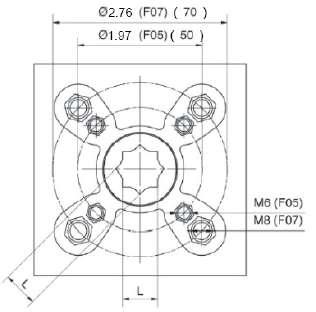
CH4 - 1770 lb-in (200
Technical specification
Nm)
Yes, by hexagonal wrench (supplied in clip) when no power is being applied. Must engage declutch button on cover first.
Not continuous, allow ≥ 1 minute between cycles


Mechanically driven dome style visual 2 colour indicator Mounting
Do not install underslung/upside down. Can install upright horizontally or vertically.
Micro-switches operated by adjustable internal cams , set slightly ahead of the final motor stop position.
Factory set at 90° ± 2°, maximum angle of rotation 360° unless multi turn series.
inch x 1.06 inch deep
*Note: x=O Failsafe Valve Open; C Failsafe Valve Closed
Page 28 R VALVES &
ACTUATORS
Dimensions
ON-OFF ELECTRIC ACTUATOR ON-OFF FAILSAFE ELECTRIC ACTUATOR Ordering code CH4GCM2 CH4FCM2 CH4GCM2Fx* CH4FCM2Fx* Rated voltage 95-265VAC/DC (50/60Hz) 24VAC/DC (50/60Hz) 95-265VAC/DC (50/60Hz) 24VAC/DC (50/60Hz) Voltage range AC: 95-265V DC: 100-300V AC: 18-26V DC: 22-28V AC: 95-265V DC: 100-300V AC: 18-26V DC: 22-28V Consumption 120 W 120 W 150 W 150 W Peak current 7.5 A 7.5 A 7.5 A 7.5 A Fuse 10 A 10 A 10 A 10 A Maximum break Torque lb-in 2124.18 lb-in 2124.18 lb-in Manual operation
Run time ≈ 25
Operating
inches
sec
frequency
Position
indication
ISO
Working angle
Female drive
Ingress protection IP67 Max media temperature ≤ 176° F Ambient temperature -4° F to 140° F Non-operating temperature -40° F to 176° F Ambient humidity 5-95% RH non-condensing Housing Plastic (ABS)
confirmation
restriction
End position
5211 F07 & F10
0.87
cover
6.72 8.78 6.28 5.79 10.5 0.87 0.87 9.13 Ø2.76 Ø4.01
CH5 - 3540 lb-in (400
Technical specification
Nm)
Yes, by hexagonal wrench (supplied in clip) when no power is being applied. Must engage declutch button on cover first
≈ 25 sec
frequency Not continuous, allow ≥ 1 minute between cycles Position confirmation Mechanically driven dome style visual 2 colour indicator
Mounting restriction Do not install underslung/upside down. Can install upright horizontally or vertically End position indication Micro-switches operated by adjustable internal cams , set slightly ahead of the final motor stop position
5211 F07 & F10
Factory set at 90° ± 2°, maximum angle of rotation 360° unless multi turn series
Page 29 R VALVES & ACTUATORS
Dimensions
ON-OFF ELECTRIC ACTUATOR ON-OFF FAILSAFE ELECTRIC ACTUATOR Ordering code CH5GCM2 CH5FCM2 NA NA Rated voltage 95-265VAC/DC (50/60Hz) 24VAC/DC (50/60Hz) Voltage range AC: 95-265V DC: 100-300V AC: 18-26V DC: 22-28V Consumption 150 W 150 W Peak current 9.3 A 9.3 A Fuse 15 A 15 A Maximum break Torque lb-in 450 Nm Manual
Run time
inches
operation
Operating
ISO
Working
Female drive 22mm x 27mm
Ingress protection IP67 Max media temperature ≤ 176° F Ambient temperature -4° F to 140° F Non-operating temperature -40° F to 176° F Ambient humidity 5-95% RH non-condensing Housing Plastic (ABS) cover 6.72 8.78 6.28 5.79 10.5 0.87 0.87 9.13 Ø2.76 Ø4.01
angle
deep
E-Tork
150 And 8850 In-Lb
Heavy Duty Electric Actuators
The ET Series Electric Actuators are available in AC and DC voltages. With output torques from 150 to 8850 inch-pound they are some of the most compact, high-output design in the market.
Technical Features:
• Direct mount on RUB ball valves, for a compact package and perfect shaft alignment
• 50% rated duty cycle reversing motor with thermal overload protection
• Rugged corrosion resistant construction with aluminum housing, durable epoxy/polyurethane
• Coating, 316 stainless shaft and fasteners
• Manual override shaft - stainless steel type 316
Price list:
• Can be wired in parallel with other E-Torks – separate circuits not required
• ISO 5211 mounting
• Fast, simple travel adjustments
• 2 limit switches for travel indication
• Heat treated steel gearing, lubricated for life
• 180° travel capability
• NEMA 4 and 4X enclosure
Page 30 R VALVES
& ACTUATORS
Model Code Torque (In/LB) Seconds 90° Power ET-1 BAA1019N 150 2.5s 110VAC BAA1019C 150 2.5s 24 VAC/VDC BAA1019A 150 2.5s 220VAC ET-2 BAA1020N 300 6s 110VAC BAA1020C 300 6s 24 VAC/VDC BAA1020A 300 6s 220VAC ET-3 BAA1021N 443 20s 110VAC BAA1021C 443 20s 24 VAC BAA1021D 443 20s 24 VDC BAA1021A 443 20s 220VAC ET-4 BAA1022N 795 15s 110VAC BAA1022C 795 15s 24 VAC BAA1022D 795 15s 24 VDC BAA1022A 795 15s 220VAC ET-5 BAA1023N 1.325 22s 110VAC BAA1023C 1.325 22s 24 VAC BAA1023D 1.325 22s 24 VDC BAA1023A 1.325 22s 220VAC ET-6 BAA1024N 2.000 26s 110VAC BAA1024C 2.000 26s 24 VAC BAA1024D 2.000 26s 24 VDC BAA1024A 2.000 26s 220VAC ET-7 BAA1025N 3.540 16s 110VAC BAA1025C 3.540 16s 24 VAC BAA1025D 3.540 16s 24 VDC BAA1025A 3.540 16s 220VAC ET-8 BAA1026N 4.425 28s 110VAC BAA1026C 4.425 28s 24 VAC BAA1026D 4.425 28s 24 VDC BAA1026A 4.425 28s 220VAC ET-9 BAA1027N 5.750 35s 110VAC BAA1027C 5.750 35s 24 VAC BAA1027D 5.750 35s 24 VDC BAA1027A 5.750 35s 220VAC ET-10 BAA1028N 8.850 46s 110VAC BAA1028C 8.850 46s 24 VAC BAA1028D 8.850 46s 24 VDC BAA1028A 8.850 46s 220VAC
Page 31 R VALVES & ACTUATORS
Model Torque In-lb Speed sec/90° A B C D E F AMPS LOCKED ROTOR WT. LBS AC 12-24 DC/AC ET-1 150 2.5 .354 (9 mm) .53 1417 (F03) M5 .44 DP 1969 (F05) M6 .46 DP .5 3.0 4.0 ET-2 300 6 .551 (14 mm) .68 1417 (F03) M5 .46 DP 1969 (F05) M6 .46 DP .5 3.0 4.0
Dimensions inches
"C" BCD
FOR COVER REMOVAL
SHAFT MINIMUM DISTANCE 1/2 NPT NEMA 4X ENCLOSURE 5.18 1.07 1.20 .44 4.24 2.12 5.66 1.78 .28 .44
"E" BCD
2.75" ABOVE
"F" THD X DEEP (4 PL)
"A" SQ. DRIVE X "B" DEEP (4 PL)
"D" THRD X DEEP
Dimensions inches
Page 32 R VALVES & ACTUATORS
Model Torque In-lb Cycle Time A B C D E F G H J K L M N ET- 3 443 20 sec 7.730 (196) 4.490 (114) 3.839 (98) 4.185 (106) 5.101 (130) 0.664 (17) M6 0.590 (15) M8 0.750 (19) 2.750 (70) 1.969 (50) -ET- 4 795 15 sec 10.04 (255) 7.87 (200) 3.55 (90.1) -13 (330) 4.92 (125) 7.87 (200) 2.76 (70) M8 .75 (19) .866 (22) 1.18 (30) - - ET- 5 1325 22 sec ET- 6 2000 26 sec ET- 7 3540 16 sec 12.40 (315) 9.21 (234) 4.92 (125) -14.96 (380) 7.68 (195) 11.81 (300) 4.02 (102) M10 .63 (16) 1.417 (36) 1.57 (40) - - ET- 8 4425 28 sec ET- 9 5750 35 sec ET- 10 8850 46 sec 23.23 (590) 10.24 (260) 7.09 (180) -17.72 (450) 11.61 (295) 13.39 (340) 5.51 (140) M16 1.14 (29) 1.378 (35) 2.36 (60) .39 (10) 1/2 NPT 2 PLACES 1/2 NPT 2 PLACES Ø H BOLT CIRCLE Ø L x M CIRCLE Ø L BOLT CIRCLE L x M DEEP J TAPPED HOLE x K DEEP ( 4 PL ) J TAPPED HOLE x K DEEP ( 4 PL ) ET- 10 ET- 3 ET- 4 ET- 5 ET- 6 ET- 7 ET- 8 ET- 9 Ø L BOL T CIRCL E Ø M BOL T CIRCL E F ST AR PATTERN G TAPPED HOLE x H DEEP ( 4 PL ) J TAPPED HOLE x K DEEP ( 4 PL ) 1/2 NPT 2 PLA CES
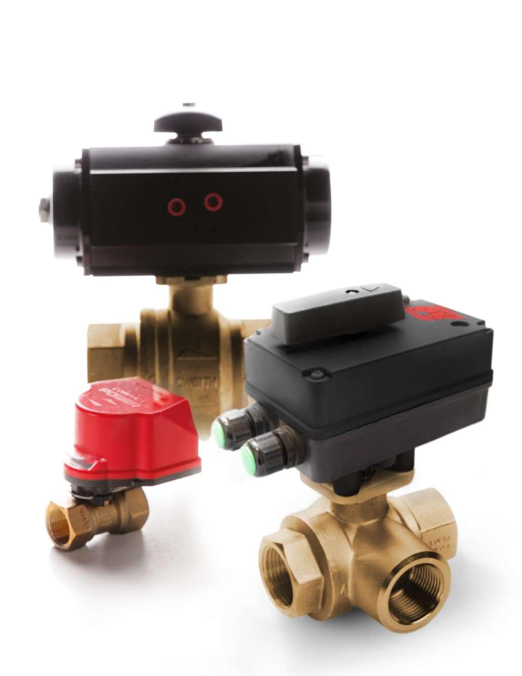
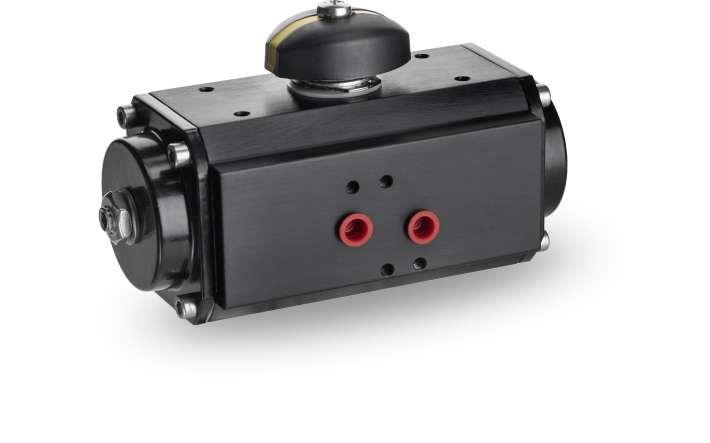
PNEUMATIC ACTUATOR
The EA actuators series is designed for quarter turn applications on RUB ball valves in a compact and lightweight design. They can be supplied single (spring return) or double acting with a wide range of output torques offering a complete valve automation solution.
EA actuator has a patented guide bar which keeps the rack and pinion gear teeth in perfect engagement in all directions of operations. The contact between the teeth is pure rolling contact – no rubbing or friction which means minimum wear and long cycle life.
Superior appearance and better corrosion resistance. It has a dense jet black anodized finish which makes the EA line suitable for indoor and outdoor applications.
Actuators are designed in compliance with the following standards:
• ISO 5211
• DIN 3337
• VDI/VDE 3845
• ATEX
• PED
- Actuator to Valve Interface Standard
- 45° Orientation of the Square Drive Shaft
- Standard for Namur mounting of accessories (switchboxes, solenoid valves, positioners)
- Explosive Atmosphere Directive (94/9/CE)
- Pressure Equipment Directive (97/23/CE)
Technical features
• ISO 5211 direct mount on valve
• Indoor or outdoor installation
• Pilot ring for perfect alignment of shaft and stem
• Nickel plated steel shaft
• Stainless steel fasteners
• High tensile long life return springs
• Visual position indicator
• Fast field conversion between double acting and spring return, fail open or fail closed
• Minimum ambient temperature while actuator is at rest: -31°F (-35°C)
• NAMUR pads for direct mount of solenoid and limit switch
• Extruded aluminum body hard anodized cylinder bore rock hard and glass smooth
Page 33 R VALVES & ACTUATORS
EA
Note: The prices refer to the double acting actuators. For single acting ask to your RUB, Inc. representative.
Auxiliary switches Code
Page 34 R VALVES & ACTUATORS
Model ISO5211 Flange Square shaft (Inch) EA4-1 F03 0.35 EA4-2 F03/F05 0.35 EA4-3 F05/F07 0.55 EA4-4 F05/F07 0.55 EA4-5 F05/F07 0.67 EA4-6 F07/F10 0.67 EA4-7 F07/F10 0.87 EA4-9 F10/F12 1.06 EA4-10 F14 1.42 EA4-12 F16 1.81
Price list:
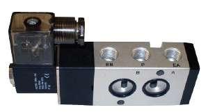
Valve Code Description AD-00001 AD-1 (UCI) COMPLETE AD-00002 AD-1 DUAL COIL 120 VAC SOLENOID AD-00003 SOLENOID VLV AD-1 5/2 3/2 110 VAC AD-00009 COILS 12 DC (28) AD-00012 COILS 24AC (16) AD-00013 COILS 24 DC (12) AD-00015 SINGLE PILOT SOLENOID AD-00016 AD-1 DUAL COIL 24 AC SOLENOID AD-00017 AD-1 (UCI) COMPLETE COIL 24 DC AD-00018 AD-1 (UCI) COMPLETE COIL 24 AC AD-00019 SOLENOID VLV AD-1 5/2 3/2 24 VAC AD-00020 COILS 220 VAC
Solenoid
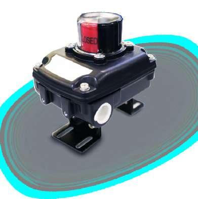
Description EA2-LS
Auxiliary switches box
Construction and materials:
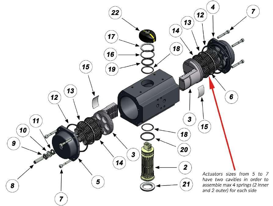
Bill of materials
EA-4 is shown. Smaller sizes have similar construction except EA-1 that has Nylon endcaps and pistons
** Polyoxymethylene commonly “Delrin”
Page 35 R VALVES & ACTUATORS
Item Description Qty Material 1 Body 1 Anod, aluminum 2 Shaft 1 Steel - zinc plated 3 Piston 2 Aluminum 4 End-cap 1 Anod, aluminum 5 End-cap (stop bolt) 1 Anod, aluminum 6 Spring 12 Max Cr-Si steel 7 Cap bolt 8 St steel 8 Stop bolt 1 Hi tensile steel 9 Stop bolt nut 1 Hi tensile steel 10 Washer 1 Polyethylene 11 O-ring (end stop) 1 NBR 12 O-ring (end cover) 2 NBR 13 Piston ring 2 POM** 14 Piston ring 2 NBR 15 Wear pad 2 POM** 16 Shaft washer 1 Polyethylene 17 Snap ring 1 Steel 18 O-ring (drive shaft) 2 NBR 19 Shaft bearing upper 1 POM** 20 Shaft bearing lower 1 POM** 21 Alignment ring 1 POM** 22 Indicator 1 Nylon
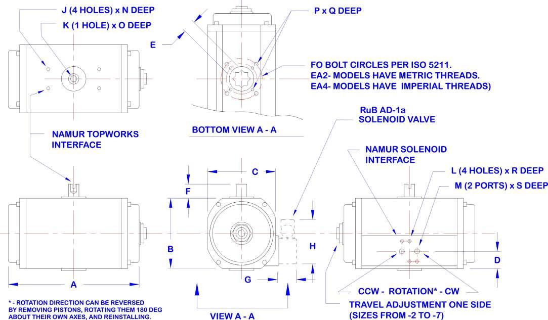
Page 36 R VALVES & ACTUATORS Dimensions: Size Imperial system - inch ISO5211 A B C D E F G H J K L M N O P Q R S 1 F03 4.06 1.77 2.01 0.89 0.35 0.79 1.02 2.64 10-32 M6 10-32 1/8 NPT 0.20 0.47 10-32 0.31 0.31 0.28 2 F03/05 5.91 2.76 2.76 0.91 0.35 0.79 1.02 2.64 10-32 M6 10-32 1/8 NPT 0.31 0.47 10-32 / 1/4”-20 0.31 / 0.39 0.31 0.39 3 F05/07 7.36 3.43 3.58 1.36 0.55 0.79 1.02 2.64 10-32 M6 10-32 1/8 NPT 0.31 0.47 1/4”-20 / 5/16”-18 0.39 / 0.51 0.31 0.39 4 F05/07 8.11 4.65 4.45 1.16 0.55 0.79 1.02 2.64 10-32 M6 10-32 1/8 NPT 0.31 0.47 1/4”-20 / 5/16”-18 0.39 / 0.51 0.31 0.39 5 F05/07 7.64 4.67 4.76 1.16 0.67 0.79 1.02 2.64 10-32 M6 10-32 1/4 NPT 0.20 0.47 1/4”-20 / 5/16”-18 0.47 / 0.47 0.31 0.50 6 F07/10 8.58 5.53 5.37 1.16 0.67 0.79 1.02 2.64 10-32 M6 10-32 1/4 NPT 0.20 0.47 5/16”-18 / 3/8”-16 0.51 / 0.63 0.31 0.50 7 F07/10 10.47 6.56 6.14 1.18 0.87 0.79 1.02 2.64 10-32 M6 10-32 1/4 NPT 0.20 0.47 5/16”-18 / 3/8”-16 0.51 / 0.63 0.31 0.50 9 F10/F12 13.39 8.17 7.52 1.65 1.06 1.18 1.02 2.64 10-32 M6 10-32 1/4 NPT 0.20 0.47 1/2 0.79 0.31 0.50 10 F14 14.21 9.84 8.94 2.4 1.42 1.18 1.02 2.64 10-32 M6 10-32 1/4 NPT 0.20 0.47 3/4 0.98 0.31 0.50 12 F16 19.52 13.31 11.81 - 1.81 1.18 1.02 2.64 10-32 M6 10-32 1/4 NPT 0.47 0.47 3/4 1.26 0.31 0.50
Torque rating charts for EA4 actuators - IMPERIAL system
Page 37 R VALVES & ACTUATORS
Double acting - torque in lb Air pressure supply (PSI) EA4- 40 50 60 70 80 90 100 1 35 44 53 62 71 80 89 2 96 120 144 168 193 217 241 3 206 258 309 361 413 464 516 4 413 516 619 722 825 928 1032 5 498 623 747 872 996 1121 1246 6 821 1027 1232 1437 1642 1848 2053 7 1522 1902 2283 2663 3044 3424 3804 9 3344.5 4180.6 5016.8 5852.9 6689.0 7525.1 8361.3 10 4552.5 5690.6 6828.8 7966.9 9105.0 10243.1 11381.3 12 10740.0 13425.0 16110.0 18795.0 21480.0 24165.0 26850.0 Spring return - Torque in lb air stroke - start air stroke - end Springs Springs Spring Torque Air pressure supply (PSI) Air pressure supply (PSI) EA4- total outer inner end start 40 50 60 70 80 90 100 110 120 40 50 60 70 80 90 100 110 120 2 2 12 23 84 108 133 157 181 205 229 253 277 73 97 121 145 169 193 218 242 266 3 18 35 78 103 127 151 175 199 223 247 271 62 86 110 134 158 182 206 230 254 4 24 46 73 97 121 145 169 193 217 241 265 50 74 98 122 146 170 194 218 242 5 30 58 67 91 115 139 163 187 211 235 259 38 82 86 111 135 159 183 207 231 6 36 70 85 109 133 157 181 205 229 253 51 75 99 123 147 171 195 219 7 41 81 79 103 127 151 175 199 223 247 39 63 87 111 135 160 184 208 8 47 93 97 121 145 169 193 217 241 52 76 100 124 148 172 196 9 53 104 115 139 163 187 211 235 84 88 112 136 160 185 10 59 116 109 133 157 181 205 230 53 77 101 125 149 173 11 65 127 127 151 175 200 224 65 89 113 137 161 12 71 139 145 170 194 218 78 102 126 150 3 2 27 48 180 231 283 334 386 436 489 541 592 158 210 261 313 364 416 488 519 571 3 40 72 166 218 270 321 373 424 476 528 579 134 186 237 289 340 392 444 495 547 4 53 96 153 205 256 308 360 411 463 514 566 110 162 213 265 316 388 419 471 523 5 66 120 140 192 243 295 346 398 449 501 553 86 138 189 241 292 344 395 447 499 6 80 144 178 230 281 333 385 436 488 539 113 165 217 268 320 371 423 475 7 93 188 165 217 268 320 371 423 474 526 89 141 193 244 296 347 399 450 8 106 193 203 255 306 358 410 461 513 117 169 220 272 323 375 426 9 119 217 242 293 345 396 448 499 144 196 248 299 351 402 10 133 241 228 280 331 383 435 486 120 172 224 275 327 378 11 146 265 267 318 370 421 473 148 199 251 303 354 12 159 289 305 356 408 460 175 227 279 330 4 2 59 91 354 457 560 663 766 869 972 1076 1179 322 425 528 631 735 838 941 1044 1147 3 89 136 324 427 530 633 737 840 943 1046 1149 277 380 483 586 689 792 896 999 1102 4 118 181 294 398 501 604 707 810 913 1016 1120 231 335 438 541 644 747 850 953 1057 5 148 227 265 368 471 574 677 781 884 987 1090 186 289 392 496 599 702 805 908 1011 6 177 272 338 442 545 648 751 854 957 1061 244 347 450 553 657 760 863 966 7 207 317 309 412 515 618 722 825 928 1031 199 302 405 508 611 714 818 921 8 236 362 382 486 589 692 795 898 1001 257 360 463 566 669 772 875 9 266 408 466 559 662 766 869 972 314 418 521 624 727 830 10 296 453 427 530 633 736 839 942 269 372 475 579 682 785 11 325 498 500 603 706 810 913 327 430 533 636 740 12 355 544 574 677 780 883 385 488 591 694 5 4 4 0 255 464 368 493 617 742 866 991 1115 1240 159 284 408 533 657 782 907 1031 5 4 1 287 522 461 585 710 834 959 1083 1208 226 350 475 599 724 849 973 6 4 2 319 580 429 553 678 803 927 1052 1176 168 292 417 541 666 791 915 7 4 3 350 637 522 646 771 895 1020 1144 234 359 484 608 733 857 8 4 4 382 695 614 739 863 988 1112 301 426 550 675 799 6 4 4 0 422 769 604 810 1015 1220 1426 1631 1836 2042 259 464 669 874 1080 1285 1490 1696 5 4 1 475 864 757 962 1168 1373 1578 1783 1989 368 573 778 984 1189 1394 1600 6 4 2 528 960 704 909 1115 1320 1525 1731 1936 272 477 682 888 1093 1298 1504 7 4 3 581 1056 856 1062 1267 1472 1678 1883 381 586 792 997 1202 1408 8 4 4 634 1152 804 1009 1214 1420 1625 1830 285 490 696 901 1106 1312 7 4 4 0 782 1423 1120 1500 1881 2261 2642 3022 3403 3783 479 860 1240 1621 2.001 2382 2762 3143 5 4 1 880 1601 1022 1403 1783 2164 2544 2924 3305 3685 302 682 1063 1443 1823 2.204 2584 2965 6 4 2 978 1778 1305 1685 2.066 2446 2827 3207 3588 504 885 1265 1646 2026 2406 2787 7 4 3 1075 1956 1207 1568 1968 2349 2729 3109 3490 326 707 1087 1468 1648 2229 2609 8 4 4 1173 2134 1490 1870 2251 2631 3012 3392 529 909 1290 1670 2051 2431 9 4 4 0 1726 3133 3282 4116 4951 5785 1877 2712 3548 4383 6 4 2 2151 3921 2858 3692 4527 5362 1098 1935 2771 3607 7 4 3 2372 4310 3472 4306 5141 1538 2374 3209 8 4 4 2584 4699 4095 4929 1986 2821 10 4 4 0 2345 4266 4470 5606 6742 7878 2554 3690 4827 5964 6 4 2 2929 5337 3881 5016 6151 7286 1485 2622 3759 4896 7 4 3 3230 5868 4723 5860 6996 2093 3230 4367 8 4 4 3522 6399 5568 6705 2700 3838 12 6 5363 8284 10711 13391 16070 18749 7797 10477 13158 15838 8 7151 11045 8928 11607 14287 16967 5042 7723 10404 13085 10 8939 13806 9824 12505 15185 4969 7651 10333 12 10726 16567 10722 13403 4898 7581
s.31 NPT Mini Valve
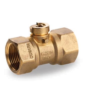
1/4” - 3/4”
Technical data:
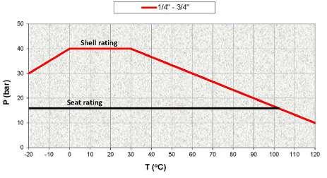
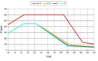
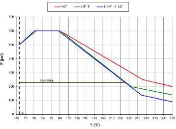
Working Pressure: 600 PSI non-shocking cold working pressure
Working Temperature: -4°F / +250°F
Threads: NPT taper ANSI B.1.20.1 threads
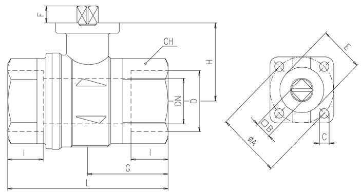
Dimensions inches
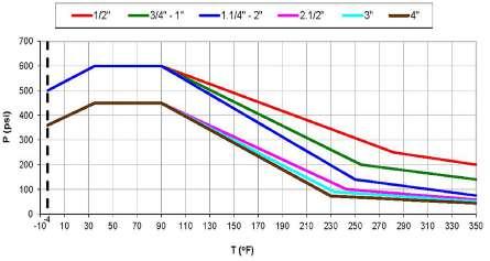
Pressure-temperature chart
Features:
• 100% seal test guaranteed in according to EN12266-1 RATE A in either direction
• Compatible with most industrial fluids including those too viscous for pilot operated valves

• Dual sealing system allows valve to be operated in either direction making installation easier
• No metal-to-metal moving parts
• No maintenance ever required
• Silicone-free lubricant
• Chrome plated ball for longer life
• Can operate also in vacuum line
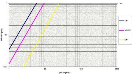
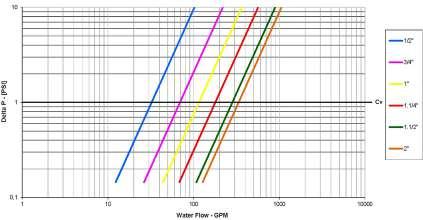
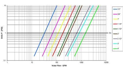
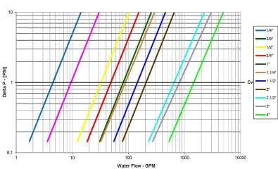
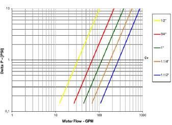
Pressure drop chart
Page 38 R VALVES & ACTUATORS
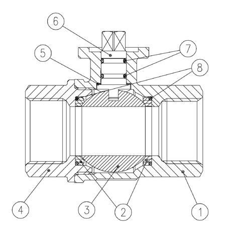
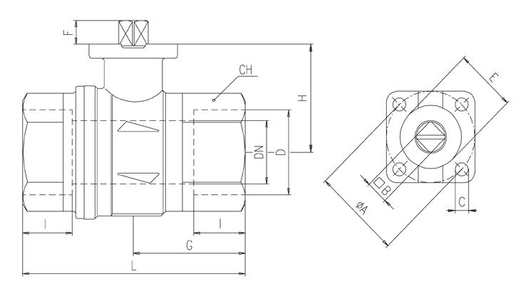
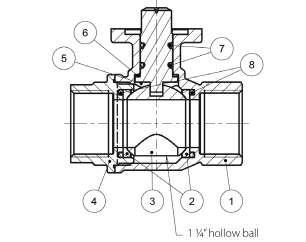
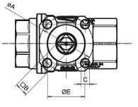
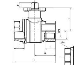
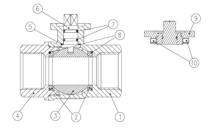
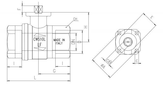
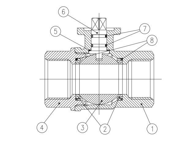
G L H A CH I I D N D D A-A 1 2 3 4 5 6 7 Part description Qty Material 1 Unplated body 1 CW617N 2 Unplated retainer nut 1 CW617N 3 Retainer seat 1 PTFE 4 Chrome plated ball 1 CW617N 5 Body seat 1 PTFE 6 Unplated stem O-Ring design 1 CW617N 7 O-Ring 2 FPM 8 Compact power electric actuator (VDC or VAC models) 1 9 Spring clip 1 AISI304 Size 1/4" 3/8" 1/2" 3/4" A 3.209 3.209 3.209 3.209 B 0.807 0.807 0.807 0.807 C 2.929 2.929 2.929 2.929 D 3.346 3.346 3.346 3.583 E 2.854 2.854 2.854 2.972 F 1.799 1.799 2.106 2.417 G 0.472 0.472 0.610 0.669 H 1/4” NPT 3/8” NPT 1/2” NPT 3/4” NPT I 0.315 0.394 0.394 0.500 L 31.496 31.496 31.496 31.496 Threads standard ANSI B1.20.1
Note for ordering code:
x = A for 230 VAC 50 Hz; B = for 110 VAC 60 Hz; C = for 24 VAC 50/60 Hz; D for 24 Vdc
y = 2 for 2 wires electrical connection; 3 for 3 wires electrical connection
Torque correction factors
Valve torque can vary according to operating frequency, temperatre and friction characteristics of the media. If media has more or less friction than water, multiply torque by the following factors.
Page 39 R VALVES & ACTUATORS Valve AV31BX3 AV31CX3 AV31DX3 AV31EX3 Valve Size 1/4” 3/8” 1/2” 3/4”
CP Electric Actuator Actuation kit CP5xy-31BX3 CP5xy-31CX3 CP5xy-31DX3 CP5xy-31EX3
for actuator sizing
Torque
Delta P → 0 - 16 Bar Valve size Nm 1/4” to 1/2” 1.8 3/4” 2.5
Lubricating oils or liquids 0.8 Dry gases, natural gas 1.5 Slurries or liquids bearing abrasive particles 1.5 to 2.5
s.6439 NPT
1/2" - 2", SS trim, ISO 5211
Technical data:
Working Pressure: 600 PSI non-shocking cold working pressure
Working Temperature: -4°F / +350°F
Threads: NPT taper ANSI B.1.20.1 female by female threads
Dimensions inches
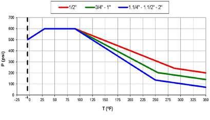
Pressure-temperature chart
Features:
• 24h 100% seal test guaranteed

• Dual sealing system allows valve to be operated in either direction making installation easier
• No metal-to-metal moving parts
• No maintenance ever required
• Silicone-free lubricant on all seals
• Stainless steel ball for longer life
• Two FPM O-rings at the stem for maximum safety
• Blowout-proof stainless steel stem
• Reinforced PTFE self-lubricanting seats with flexible-lip and wear compensation design
Pressure drop chart

Page 40 R VALVES & ACTUATORS
Part description Qty Material 1 Unplated body 1 CW617N 2 Ball seat 2 PTFE graphite filled 15% 3 Stainless steel ball 1 AISI316 4 Unplated end-cap 1 CW617N 5 Washer 1 PTFE carbon filled 25% 6 Stainless steel stem O-ring design 1 AISI316 7 O-Ring 2 FPM 8 O-Ring 2 FPM Code S64D39 S64E39 S64F39 S64G39 S64H39 S64I39 D 1/2" 3/4" 1" 1 1/4" 1 1/2" 2" DN 0.590 0.787 0.984 1.259 1.575 1.968 I 0.610 0.708 0.826 0.905 0.964 1.043 L 2.598 2.933 3.562 4.094 4.606 5.314 G 1.201 1.456 1.791 2.047 2.322 2.657 H 1.220 1.515 1.673 2.185 2.441 2.716 CH 1.063 1.259 1.614 1.968 2.165 2.756 ØA 1.417 1.417 1.417 1.968 1.968 1.968 B 0.354 0.354 0.354 0.551 0.551 0.551 C 0.220 0.220 0.220 0.259 0.259 0.259 E 0.984 0.984 0.984 1.378 1.378 1.378 F 0.295 0.334 0.334 0.570 0.570 0.570 Flange connection DIN ISO 5211 DIN 3337 F03 F03 F03 F05 F05 F05
note for code:
x = A for 230 VAC 50 Hz; B = for 110 VAC ac 60 Hz; C = for 24 VAC 50/60 Hz; D for 24 Vdc
y = 2 for 2 wires electrical connection; 3 for 3 wires electrical connection
All the selection are made for delta P 0 - 200 PSI
Torque for actuator sizing in-lb
Torque correction factors
Valve torque can vary according to operating frequency, temperatre and friction characteristics of the media.
If media has more or less friction than water, multiply torque by the following factors.
Page 41 R VALVES & ACTUATORS Valve S64D39 S64E39 S64F39 S64G39 S64H39 S64I39 Valve Size 1/2” 3/4” 1” 1 1/4” 1 1/2” 2” Double acting pneumatic actuator Actuator EA4-1 EA4-3 Actuation kit EA1D64D39 EA1D64E39 EA1D64F39 EA3D64G39 EA3D64H39 EA3D64I39 120 VAC, On/Off Actuator ET-1 ET-2 Actuation kit ET1B64D39 ET1B64E39 ET1B64F39 ET2B64G39 ET2B64H39 ET2B64I39 120 VAC, On/Off Actuator CT1 - 8Nm CT4 - 40Nm Actuation kit CT1BAN164D39 CT1BAN164E39 CT1BAN164F39 CT4ICM264G39 CT4ICM264H39 CT4ICM264I39 CP Electric Actuator Actuation kit CP5xy-64D39 CP5xy-64E39 - - -Spring return pneumatic actuator Actuator EA4-2 EA4-3 EA4-4 Actuation kit EA2R64D39 EA2R64E39 EA2R64F39 EA3R64G39 EA3R64H39 EA4R64I39 24 VAC, On/Off Actuator ET-1 ET-2 Actuation kit ET1C64D39 ET1C64E39 ET1C64F39 ET2C64G39 ET2C64H39 ET2C64I39 24 VAC, On/Off Actuator CT1 - 8Nm CT4 - 40Nm Actuation kit CT1CAN164D39 CT1CAN164E39 CT1CAN164F39 CT4LCM264G39 CT4LCM264H39 CT4LCM264I39
Delta P --> 0 - 200 PSI 600 PSI Valve Size to open to close to open to close 1/2” 25 15 25 15 3/4” 33 20 33 20 1” 62 37 62 37 1 1/4” 104 111 121 111 1 1/2” 220 180 273 180 2” 262 222 327 222 ET electric actuator EA pneumatic actuator CT electric actuator CP electric actuator
note for code:
Lubricating oils or liquids 0.8 Dry gases, natural gas 1.5 Slurries or liquids bearing abrasive particles 1.5 to 2.5
s.6439 LT NPT
1" - 2", SS trim, ISO 5211, low torque
Technical data:
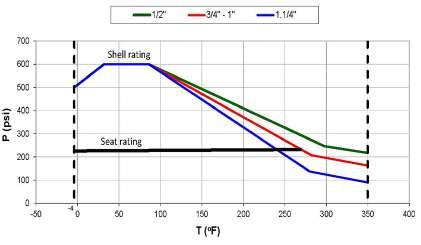
Working Pressure: Shell rating: 600 PSI | Seat rating: Delta P max permissible 230 PSI non-shock cold working pressure
Working Temperature: -4°F / +350°F
Threads: NPT taper ANSI B.1.20.1 female by female threads
Dimensions inches
Pressure-temperature chart
Features:
• Dual sealing system allows valve to be operated in either direction making installation easier

• No metal-to-metal moving parts
• No maintenance ever required
• Silicone-free lubricant on all seals
• Stainless steel ball for longer life
• 100% seal test guaranteed in according to EN 12266-1
Pressure drop chart
Page 42 R VALVES & ACTUATORS
RATE A
Part description Qty Material 1 Unplated body 1 CW617N 2 Ball seat 2 PTFE graphite filled 3 Stainless steel ball 1 AISI316 4 Unplated end-cap 1 CW617N 5 Washer 1 PTFE carbon filled 25% 6 Stainless steel stem O-ring design 1 AISI316 7 O-Ring 2 FPM 8 O-Ring 2 FPM Code S64F39A S64G39A S64H39A S64I39A D 1" 1 1/4" 1 1/2" 2" DN 0.984 1.259 1.575 1.968 I 0.826 0.905 0.964 1.043 L 3.562 4.094 4.606 5.314 G 1.791 2.047 2.322 2.657 H 1.673 1.949 2.441 2.716 CH 1.614 1.968 2.165 2.756 ØA 1.417 1.417 1.968 1.968 B 0.354 0.354 0.551 0.551 C 0.220 0.220 0.259 0.259 E 0.984 0.984 1.378 1.378 F 0.334 0.570 0.570 0.570 Flange connection DIN ISO 5211 DIN 3337 F03 F03 F05 F05
note for code:
x = A for 230 VAC 50 Hz; B = for 110 VAC ac 60 Hz; C = for 24 VAC 50/60 Hz; D for 24 Vdc
y = 2 for 2 wires electrical connection; 3 for 3 wires electrical connection
electric actuator
note for code:
All the selection are made for delta P 0 - 200 PSI
Torque for actuator sizing in-lb
Torque correction factors
Valve torque can vary according to operating frequency, temperatre and friction characteristics of the media.
If media has more or less friction than water, multiply torque by the following factors.
Page 43 R VALVES & ACTUATORS
Delta P --> 0 - 90 PSI > 90 - 230 PSI Valve Size to open to close to open to close 1” 19 19 31 31 1 1/4” 22 22 35 35 1 1/2” 51 51 84 84 2” 70 70 115 115
Lubricating oils or liquids 0.8 Dry gases, natural gas 1.5 Slurries or
abrasive particles 1.5 to 2.5 Valve S64F39A S64G39A S64H39A S64I39A Valve Size 1” 1 1/4” 1 1/2” 2” Double acting pneumatic actuator Actuator EA4-1 EA4-3 Actuation kit EA1D64F39A EA1D64G39A EA3D64H39A EA3D64I39A 120 VAC, On/Off Actuator ET-1 ET-2 Actuation kit ET1B64F39A ET1B64G39A ET2B64H39A ET2B64I39A 120 VAC, On/Off Actuator CT1 - 8Nm CT4 - 40Nm Actuation kit CT1BAN164F39A CT1BAN164G39A CT4ICM264H39A CT4ICM264I39A CP Electric Actuator Actuation kit CP5xy-64F39A CP5xy-64G39A -Spring return pneumatic actuator Delta P < 90 PSI Actuator EA4-2 EA4-3 Actuation kit EA2R64F39A EA2R64G39A EA3R64H39A EA3R64I39A Spring return pneumatic actuator Delta P 91 to 230 PSI Actuator EA4-2 EA4-3 Actuation kit EA2R64F39A EA2R64G39A EA3R64H39A EA3R64I39A 24 VAC, On/Off Actuator ET-1 ET-2 Actuation kit ET1C64F39A ET1C64G39A ET2C64H39A ET2C64I39A 24 VAC, On/Off Actuator CT1 - 8Nm CT4 - 40Nm Actuation kit CT1CAN164F39A CT1CAN164G39A CT4LCM264H39A CT4LCM264I39A
liquids bearing
ET electric
EA pneumatic
CT
CP
actuator
actuator
electric actuator
s.6441 NPT
Technical data:
Working Pressure: 600 PSI up to 2”, 450 PSI over 2” non-shock cold working pressure
Working Temperature: -4°F / +350°F
Threads: NPT taper ANSI B.1.20.1 female by female threads
Dimensions inches
Ball seats and stem configuration of valves over 2” is different.
Pressure-temperature chart
Features:
• 24h 100% seal test guaranteed
• Dual sealing system allows valve to be operated in either direction making installation easier
• No metal-to-metal moving parts
• No maintenance ever required
• Silicone-free lubricant on all seals
• Chrome plated brass ball for longer life
Pressure drop chart
Page 44 R VALVES &
ACTUATORS
1/2" - 4" brass trim, ISO 5211 Part description Qty Material 1 Unplated body 1 CW617N 2 Ball seat 2 PTFE graphite filled 15% 3 Chrome plated ball 1 CW617N 4 Unplated end-cap 1 CW617N 5 Washer 1 PTFE carbon filled 25% 6 Nickel plated stem O-ring design 1 CW617N 7 O-Ring 2 FPM 8 O-Ring 2 FPM Code S64D41 S64E41 S64F41 S64G41 S64H41 S64I41 D 1/2" 3/4" 1" 1 1/4" 1 1/2" 2" DN 0.590 0.787 0.984 1.259 1.575 1.968 I 0.610 0.708 0.826 0.905 0.964 1.043 L 2.598 2.933 3.562 4.094 4.606 5.314 G 1.201 1.456 1.791 2.047 2.322 2.657 H 1.220 1.515 1.673 2.185 2.441 2.716 CH 1.063 1.259 1.614 1.968 2.165 2.756 ØA 1.417 1.417 1.417 1.968 1.968 1.968 B 0.354 0.354 0.354 0.551 0.551 0.551 C 0.220 0.220 0.220 0.259 0.259 0.259 E 0.984 0.984 0.984 1.378 1.378 1.378 F 0.295 0.334 0.334 0.570 0.570 0.570 Flange connection DIN ISO 5211 DIN 3337 F03 F03 F03 F05 F05 F05
Valves configuration up to 2”
Torque for actuator sizing in-lb
Torque correction factors
Valve torque can vary according to operating frequency, temperatre and friction characteristics of the media.
If media has more or less friction than water, multiply torque by the following factors.
Page 45 R VALVES & ACTUATORS
Delta P --> 0 - 200 PSI 600 PSI (450 PSI over 2”) Valve Size to open to close to open to close 1/2” 25 15 25 15 3/4” 33 20 33 20 1” 62 37 62 37 1 1/4” 104 111 121 111 1 1/2” 220 180 273 180 2” 262 222 327 222
Lubricating oils or liquids 0.8 Dry gases, natural gas 1.5 Slurries or liquids bearing abrasive particles 1.5 to 2.5 Valve S64D41 S64E41 S64F41 S64G41 S64H41 S64I41 Valve Size 1/2” 3/4” 1” 1 1/4” 1 1/2” 2” Double acting pneumatic actuator Actuator EA4-1 EA4-3 Actuation kit EA1D64D41 EA1D64E41 EA1D64F41 EA3D64G41 EA3D64H41 EA3D64I41 120 VAC, On/Off Actuator ET-1 ET-2 Actuation kit ET1B64D41 ET1B64E41 ET1B64F41 ET2B64G41 ET2B64H41 ET2B64I41 120 VAC, On/Off Actuator CT1 - 8Nm CT4 - 40Nm Actuation kit CT1BAN164D41 CT1BAN164E41 CT1BAN164F41 CT4ICM264G41 CT4ICM264H41 CT4ICM264I41 Spring return pneumatic actuator Actuator EA4-2 EA4-3 EA4-4 Actuation kit EA2R64D41 EA2R64E41 EA2R64F41 EA3R64G41 EA3R64H41 EA4R64I41 24 VAC, On/Off Actuator ET-1 ET-2 Actuation kit ET1C64D41 ET1C64E41 ET1C64F41 ET2C64G41 ET2C64H41 ET2C64I41 24 VAC, On/Off Actuator CT1 - 8Nm CT4 - 40Nm Actuation kit CT1CAN164D41 CT1CAN164E41 CT1CAN164F41 CT4LCM264G41 CT4LCM264H41 CT4LCM264I41 ET electric actuator EA pneumatic actuator CT electric actuator note for code: All the selection are made for delta P 0 - 200 PSI
s.6541 NPT
1/2" - 1 1/4" hot forged brass ball valve
Technical data:
Working Pressure: 600 PSI non-shock cold working pressure
Working Temperature: -4°F / +302°F
Threads: NPT taper ANSI B.1.20.1 female by female threads
Dimensions inches
DN shows the nominal flow diameter. Actual flow diameter complies with full port DIN 3357 part 4.
Pressure-temperature chart
Features:
• 24h 100% seal test guaranteed in according to EN 12266-1 RATE A
• Dual sealing system allows valve to be operated in either direction making installation easier
• No metal-to-metal moving parts
• No maintenance ever required
• Silicone-free lubricant on all seals
• Chrome plated brass ball for longer life
Pressure drop chart
Page 46 R VALVES &
ACTUATORS
Part description Qty Material 1 Sand blasted unplated body 1 CW617N 2 Seat 2 PTFE 3 Chrome plated ball with rinse hole (rinse hole on sizes from 3/4” up to 1 1/4”) 1 CW617N 4 Sand blasted unplated end cap 1 CW617N 5 Washer 1 PTFE carbon filled 25% 6 Nickel plated stem O-ring design 1 CW617N 7 O-Ring 2 EPDM 8 O-Ring 2 EPDM Code S65D41 S65E41 S65F41 S65G41 D 1/2" 3/4" 1" 1 1/4" DN 0.591 0.748 0.945 1.181 I 0.610 0.669 0.827 0.906 L 2.500 2.677 3.346 3.819 G 1.240 1.339 1.673 1.909 H 1.220 1.496 1.626 1.890 CH 0.984 1.220 1.575 1.929 ØA 1.417 1.417 1.417 1.417 B 0.354 0.354 0.354 0.354 C 0.220 0.220 0.220 0.220 ØE 0.984 0.984 0.984 0.984 F 0.287 0.327 0.327 0.327 Flange connection DIN ISO 5211 DIN 3337 F03 F03 F03 F03
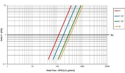
0,1 1 10 11 01 00 1000 De lt a P[PS I] Wa ter Flow - GPM 1/2" 3/4" 1" 1.1/4" Cv -4 0 100 200 300 400 500 600 700 -20 30 80 130 180 230 280 330 P (psi) T (oF) 1/2" 3/4" - 1" 1.1/4" Seat rating Shell rating
note for code:
x = A for 230 VAC 50 Hz; B = for 110 VAC ac 60 Hz; C = for 24 VAC 50/60 Hz; D for 24 Vdc
y = 2 for 2 wires electrical connection; 3 for 3 wires electrical connection
note for code:
All the selection are made for delta P 0 - 230 PSI
Torque for actuator sizing in-lb
Torque correction factors
Valve torque can vary according to operating frequency, temperatre and friction characteristics of the media.
If media has more or less friction than water, multiply torque by the following factors.
Page 47 R VALVES & ACTUATORS
Delta P --> 0 - 200 PSI Valve Size to open to close 1/2” 31 27 3/4” 37.5 33 1” 40 35.5 1 1/4” 44.5 40
Lubricating oils or liquids 0.8 Dry gases, natural gas 1.5
or liquids
abrasive
1.5 to 2.5 Valve S65D41 S65E41 S65F41 S65G41 Valve Size 1/2” 3/4” 1” 1 1/4” Double acting pneumatic actuator Actuator EA4-1 Actuation kit EA1D65D41 EA1D65E41 EA1D65F41 EA1D65G41 120 VAC, On/Off Actuator ET-1 Actuation kit ET1B65D41 ET1B65E41 ET1B65F41 ET1B65G41 120 VAC, On/Off Actuator CT1 Actuation kit CT1BAN65D41 CT1BAN65E41 CT1BAN65F41 CT1BAN65G41 Spring return pneumatic actuator Actuator EA4-2 Actuation kit EA2R65D41 EA2R65E41 EA2R65F41 EA2R65G41 24 VAC, On/Off Actuator ET-1 Actuation kit ET1C65D41 ET1C65F41 ET1C65F41 ET1C65G41 24 VAC, On/Off Actuator CT1 Actuation kit CT1CAN65D41 CT1CAN65E41 CT1CAN65F41 CT1CAN65G41 ET electric actuator EA pneumatic actuator CT electric
Slurries
bearing
particles
actuator
CP Electric Actuator Actuation kit CP5xy65D41 CP5xy65E41 CP5xy65F41 CP5xy65G41
CP electric actuator
s.95 NPT
2 1/2”- 4” brass trim, ISO 5211
Technical data:
Working Pressure: 450 PSI non-shock cold working pressure
Working Temperature: -40°F/+350°F
Threads: NPT taper ANSI B.1.20.1 female by female threads
Dimensions inches
Ball seats and stem configuration of valves over DN shows the nominal flow diameter. Actual flow diameter complies with full port DIN 3357 part 4.
Pressure-temperature chart
Features:
• 24h 100% seal test guaranteed
• Dual sealing system allows valve to be operated in either direction making installation easier
• No metal-to-metal moving parts
• Silicone-free lubricant on all seals


• Chrome plated brass ball for longer life
• No maintenance ever required
Pressure drop chart
Page 48 R VALVES
& ACTUATORS
Code S95L41AM S95M41AM S95N41AM D 2 1/2" 3" 4" DN 2.559 3.150 3.937 I 1.260 1.378 1.634 L 6.142 6.969 8.504 G 3.071 3.484 4.252 H 3.502 3.779 4.366 CH 3.346 3.898 4.921 ØA 2.756 2.756 2.756 B 0.669 0.669 0.669 C 0.335 0.335 0.335 E 2.165 2.165 2.165 F 0.709 0.709 0.709 Flange connection DIN ISO 5211 DIN 3337 F07 F07 F07 Part description Qty Material 1 Unplated body 1 CW617N 2 Ball seat 2 PTFE graphite filled 15% 3 Chrome plated ball 1 CW617N 4 Unplated end-cap 1 CW617N 5 Washer 1 PTFE carbon filled 25% 6 Nickel plated stem O-ring design 1 CW617N 7 O-Ring 2 FPM 8 O-Ring 2 FPM 9 Black anodized flange 1 Aluminum 10 Grub screw 2 CB4FF
Torque for actuator sizing in-lb
Torque correction factors
Valve torque can vary according to operating frequency, temperatre and friction characteristics of the media.
If media has more or less friction than water, multiply torque by the following factors.
Page 49 R VALVES & ACTUATORS
Delta P --> 0 - 200 PSI 600 PSI (450 PSI over 2”) Valve Size to open to close to open to close 2 1/2” 372 372 929 929 3” 902 902 1062 1062 4” 1646 1646 1991 1991
Lubricating oils or liquids 0.8 Dry gases, natural gas 1.5 Slurries or liquids
abrasive particles 1.5 to 2.5 Valve S95L41AM S95M41AM S95N41AM Valve Size 2 1/2” 3” 4” Double acting pneumatic actuator Actuator EA4-5 EA4-7 Actuation kit EA5D95L41AM EA5D95M41AM EA7D95N41AM 120 VAC, On/Off Actuator ET-3 ET-5 ET-6 Actuation kit ET3B95L41AM ET5B95M41AM ET6B95N41AM ΔP 0 - 200 PSI Actuator CH1 CH3 CH4 Actuation kit S95L41AM S95M41AM S95N41AM ΔP 200 - 450 PSI Actuator CH3 CH4 CH5 Actuation kit S95L41AM S95M41AM S95N41AM Spring return pneumatic actuator Actuator EA4-5 EA4-6 EA4-7 Actuation kit EA5R95L41AM EA6R95M41AM EA7R95N41AM 24 VAC, On/Off Actuator ET-3 ET-5 ET-6 Actuation kit ET3C95L41AM ET5C95M41AM ET6C95N41AM ET electric actuator CH electric actuator EA pneumatic actuator
bearing
Puri-T 264 NPT
1/2" - 1 1/2" Lead Free, ISO 5211

All surfaces of this product in contact with drinking water contain less than 0.25% of lead in compliance with U.S. law
Technical data:
Working Pressure: 600 PSI up to 3/4" size, For 1" size up to 1 1/2" size:
- Seat rating: Delta P max permissible 230 PSI
- Shell rating: 600 PSI
non-shock cold working pressure
Working Temperature: -4°F/+350°F
Threads: NPT taper ANSI B.1.20.1 female by female threads
Dimensions inches
Pressure-temperature chart
Features:
• Certified by CSA International to comply with U.S. s3874, California AB1953, and similar laws of other states for the safe handling of drinking water

• 24h 100% seal test guaranteed
• Dual sealing s ystem allows valve to be operated in either direction making installation easier
• No metal-to-metal moving parts
• No maintenance ever required
• Silicone-free lubricant on all seals
• Chrome plated lead free brass ball for longer life
Pressure drop chart
Page 50 R VALVES
& ACTUATORS
Code T264D41 T264E41 T264F41 T264G41 T264H41 D 1/2" 3/4" 1" 1 1/4" 1 1/2" DN 0.590 0.787 0.984 1.259 1.575 I 0.610 0.708 0.826 0.905 0.964 L 2.598 2.933 3.562 4.094 4.606 G 1.201 1.456 1.791 2.047 2.322 H 1.220 1.515 1.673 1.941 2.441 CH 1.063 1.259 1.614 1.968 2.165 ØA 1.417 1.417 1.417 1.417 1.968 B 0.354 0.354 0.354 0.354 0.551 C 0.220 0.220 0.220 0.220 0.259 E 0.984 0.984 0.984 0.984 1.378 F 0.295 0.334 0.334 0.334 0.570 Flange connection DIN ISO 5211 DIN 3337 F03 F03 F03 F03 F05 Part description Qty Material 1 Unplated NPT body 1 CW510L 2 Ball seat 2 PTFE graphite filled 15% up to 3/4" size, PTFE carbographite filled over 3/4" size 3 Chrome plated ball 1 CW510L 4 Unplated NPT endcap 1 CW510L 5 Washer 1 PTFE carbon filled 25% 6 Nickel plated stem O-ring design 1 CW510L 7 O-Ring 2 FPM 8 O-Ring 2 FPM
note for code:
x = A for 230 VAC 50 Hz; B = for 110 VAC ac 60 Hz; C = for 24 VAC 50/60 Hz; D for 24 Vdc
y = 2 for 2 wires electrical connection; 3 for 3 wires electrical connection
electric actuator
note for code:
All the selection are made for delta P 0 - 230 PSI
Torque for actuator sizing in-lb
Water flow ratings
Torque correction factors
Valve torque can vary according to operating frequency, temperatre and friction characteristics of the media. If media has more or less friction than water, multiply torque by the following factors.
Page 51 R VALVES & ACTUATORS
Delta P --> 0 - 200 PSI 600 PSI Valve Size to open to close to open to close 1/2” 25 15 25 15 3/4” 33 20 33 20 Delta P --> 0 - 90 PSI > 90 - 230 PSI Valve Size to open to close to open to close 1” 19 19 31 31 1 1/4” 22 22 35 35 1 1/2” 51 51 84 84 Size T264D41 T264E41 T264F41 T264G41 T264H41 CV 32.3 69.3 115.5 179.1 283.1
Lubricating oils or liquids 0.8 Dry gases, natural gas 1.5 Slurries or liquids bearing abrasive particles 1.5 to 2.5 Valve T264D41 T264E41 T264F41 T264G41 T264H41 Valve Size 1/2" 3/4" 1" 1 1/4" 1 1/2" Double acting pneumatic actuator Actuator EA4-1 EA4-3 Actuation kit EA1D264D41 EA1D264E41 EA1D264F41 EA1D264G41 EA3D264H41 120 VAC, On/Off Actuator ET-1 Actuation kit ET1B264D41 ET1B264E41 ET1B264F41 ET1B264G41 ET1B264H41 120 VAC, On/Off Actuator CT1 - 8Nm CT4 - 40Nm Actuation kit CT1BAN1264D41 CT1BAN1264E41 CT1BAN1264F41 CT1BAN1264G41 CT4ICM2264H41 CP Electric Actuator Actuation kit CP5xy-264D41 CP5xy-264E41 CP5xy-264F41 CP5xy-264G41Spring return pneumatic actuator Actuator EA4-2 EA4-3 Actuation kit EA2R264D41 EA2R264E41 EA2R264F41 EA2R264G41 EA3R264H41 24 VAC, On/Off Actuator ET-1 Actuation kit ET1C264D41 ET1C264E41 ET1C264F41 ET1C264G41 ET1C264H41 24 VAC, On/Off Actuator CT1 - 8Nm CT4 - 40Nm Actuation kit CT1CAN1264D41 CT1CAN1264E41 CT1CAN1264F41 CT1CAN1264G41 CT4LCM2264H41
ET
EA pneumatic
CT
CP
electric actuator
actuator
electric actuator
s.7341
NPT 3-way 4 seats T-port
Technical data:
Working Pressure: 300 PSI non-shock cold working pressure
Working Temperature: -4°F / +302°F
Threads: NPT taper ANSI B.1.20.1 female by female threads
Dimensions inches
• Electronic 100% seal test guaranteed
• No metal-to-metal moving parts
• No maintenance ever required
• Silicone-free lubricant on all seals
• Chrome plated brass ball for longer life
• Each valve is seal tested for maximum safety
• Performs well in any orientation
• Strong configuration
Page 52 R VALVES
& ACTUATORS
1/2" - 2" ISO 5211 Part description Qty Material 1 Sand blasted unplated body 1 CW617N 2 Seat 2 PTFE 3 Seat 2 PTFE 4 Chrome plated ball 1 CW617N 5 Sand blasted unplated end-cap 1 CW617N 6 Washer 1 PTFE carbon filled 25% 7 Nickel plated stem O-ring design 1 CW617N 8 Green O-Ring 2 FPM 9 O-Ring 2 FPM 10 O-Ring 2 FPM 11 Unplated O-Ring 2 CW617N Features: Code S73D41 S73E41 S73F41 S73G41 S73H41 S73I41 Size 1/2" 3/4" 1" 1 1/4" 1 1/2" 2" DN 0.591 0.787 0.984 1.197 1.496 1.890 I 0.610 0.709 0.827 0.906 0.965 1.043 L 2.559 3.110 3.642 4.311 4.961 5.906 G 1.280 1.555 1.831 2.165 2.480 2.953 H 1.280 1.555 1.673 2.205 2.500 2.854 N 1.358 1.654 1.949 2.362 2.717 3.228 ØA 1.417 1.417 1.417 1.969 1.969 1.969 ØC Ø 0.22 Ø 0.22 Ø 0.22 Ø 0.26 Ø 0.26 Ø 0.26 ØE 0.984 0.984 0.984 1.378 1.378 1.378 B 0.354 0.354 0.354 0.551 0.551 0.551 ØM 1.709 1.709 1.709 2.394 2.394 2.394 S 0.087 0.087 0.087 0.126 0.126 0.126 T 0.394 0.394 0.394 0.551 0.551 0.551 F 0.287 0.327 0.327 0.571 0.571 0.571 CH 1.063 1.260 1.614 1.969 2.165 2.756 1 2 4 5 7 6 8 1.1/4"-2" Po rt A-B se at configuration 9 1.1/4"-2" Port C seat configur ation 11 10 M D N D I I G L H F P T CH S D AA B ØM ØA N I øC
D 3
ØE
(4x)
Stem slot shows all ports are open
Torque for actuator sizing in-lb
Torque correction factors
Valve torque can vary according to operating frequency, temperatre and friction characteristics of the media.
If media has more or less friction than water, multiply torque by the following factors.
Page 53 R VALVES & ACTUATORS
Delta P --> 0 - 230 PSI Valve Size to open to close 1/2” 93 93 3/4” 115 115 1” 195 195 1 1/4" 124 124 1 1/2" 204 204 2 336 336 note for code: All the selection are made for delta P 0 - 230 PSI
Lubricating oils or liquids 0.8 Dry gases, natural gas 1.5 Slurries or liquids bearing abrasive particles 1.5 to 2.5 Valve S73D41 S73E41 S73F41 S73G41 S73H41 S73I41 Valve Size 1/2" 3/4" 1" 1 1/4" 1 1/2" 2" Double acting pneumatic actuator Actuator EA4-2 EA4-3 Actuation kit EA2D73D41 EA2D73E41 EA3D73F41 EA3D73G41 EA3D73H41 EA3D73I41 120 VAC, On/Off Actuator ET-1 ET-2 ET-3 Actuation kit ET1B73D41 ET1B73E41 ET2B73F41 ET2B73G41 ET2B73H41 ET3B73I41 120 VAC, On/Off Actuator CT2 CT3 CT4 Actuation kit CT2BCM273D41 CT3BCM273E41 CT3ICM273F41 (LK9 is required) CT4ICM273G41 CT4ICM273H41 CT4ICM273I41 24 VAC, On/Off Actuator CT2 CT3 CT4 Actuation kit CT2CCM273D41 CT3CCM273E41 CT3LCM273F41 (LK9 is required) CT4LCM273G41 CT4LCM273H41 CT4LCM273I41 Spring return pneumatic actuator Actuator EA4-3 EA4-4 EA4-3 EA4-4 Actuation kit EA3R73D41 EA3R73E41 EA4R73F41 EA3R73G41 EA4R73H41 EA4R73I41 24 VAC, On/Off Actuator ET-1 ET-2 ET-3 Actuation kit ET1C73D41 ET1C73E41 ET2C73F41 ET2C73G41 ET2C73H41 ET3C73I41 ET electric actuator CT electric actuator EA pneumatic actuator
s.7641 NPT
1/2" - 2" ISO 5211
3-way 2 seats L-port (diverting)
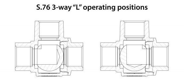
Technical data:
Working Pressure: 450 PSI non-shock cold working pressure
Working Temperature: -4°F / +302°F
Threads: NPT taper ANSI B.1.20.1 female threads
Dimensions inches
• Electronic 100% seal test guaranteed
• No metal-to-metal moving parts
• No maintenance ever required
• Silicone-free lubricant on all seals
• Chrome plated brass ball for longer life
• Each valve is seal tested for maximum safety
• Performs well in any orientation
• Strong configuration
Page 54 R VALVES & ACTUATORS
Part description Qty Material 1 Sand blasted unplated body 1 CW617N 2 Seat 2 PTFE 15% GRF up to 1", PTFE over 1" 3 Chrome plated ball 1 CW617N 4 Sand blasted unplated end-cap 1 CW617N 5 Washer 1 PTFE carbon filled 25% 6 Nickel plated stem O-ring design 1 CW617N 7 Green O-Ring 2 FPM 8 O-Ring 2 FPM
Code S76D41 S76E41 S76F41 S76G41 S76H41 S76I41 Size 1/2" 3/4" 1” 1 1/4" 1 1/2" 2" DN 0.591 0.787 0.984 1.197 1.496 1.890 I 0.610 0.709 0.827 0.906 0.965 1.043 L 2.559 3.110 3.642 4.311 4.961 5.906 G 1.280 1.555 1.831 2.165 2.480 2.953 H 1.820 1.555 1.673 2.205 2.500 2.854 N 1.358 1.654 1.949 2.362 2.717 3.228 ØA 1.417 1.417 1.417 1.969 1.969 1.969 ØC Ø 0.22 Ø 0.22 Ø 0.22 Ø 0.26 Ø 0.26 Ø 0.26 ØE 0.984 0.984 0.984 1.378 1.378 1.378 Square B 0.354 0.354 0.354 0.551 0.551 0.551 ØM 1.709 1.709 1.709 2.394 2.394 2.394 S 0.087 0.087 0.087 0.126 0.126 0.126 T 0.394 0.394 0.394 0.551 0.551 0.551 F 0.287 0.327 0.327 0.571 0.571 0.571 CH 1.063 1.260 1.614 1.969 2.165 2.756
Features:
1 2 3 4 6 5 7 8 M D N D I I G L H F P T CH S D AA B ØM ØA N I øC (4x) D Stem slot shows L ports position ØE
x = A for 230 VAC 50 Hz; B = for 110 VAC ac 60 Hz; C = for 24 VAC 50/60 Hz; D for 24 Vdc
y = 2 for 2 wires electrical connection; 3 for 3 wires electrical connection
note for code:
All the selection are made for delta P 0 - 200 PSI
Torque for actuator sizing in-lb
Torque correction factors
Valve torque can vary according to operating frequency, temperatre and friction characteristics of the media.
If media has more or less friction than water, multiply torque by the following factors.
Page 55 R VALVES & ACTUATORS
Lubricating oils or liquids 0.8 Dry gases, natural gas 1.5 Slurries or liquids bearing abrasive particles 1.5 to 2.5 Delta P --> 0 - 450 PSI Valve Size to open to close 1/2” 31 31 3/4” 36 36 1" 40 40 1 1/2" 104 104 1 1/4" 190 190 2” 248 248
Valve S76D41 S76E41 S76F41 S76G41 S76H41 S76I41 Valve Size 1/2" 3/4" 1" 1 1/4" 1 1/2" 2" Double acting pneumatic actuator Actuator EA4-1 EA4-3 Actuation kit EA1D76D41 EA1D76E41 EA1D76F41 EA3D76G41 EA3D76H41 EA3D76I41 120 VAC, On/Off Actuator ET-1 ET-2 ET-3 Actuation kit ET1B76D41 ET1B76E41 ET1B76F41 ET2B76G41 ET2B76H41 ET3B76I41 120 VAC, On/Off Actuator CT1 CT4 Actuation kit CT1BAN176D41 CT1BAN176E41 CT1BAN176F41 CT4IAN176G41 CT4IAN176H41 CT4IAN176I41 24 VAC, On/Off Actuator CT1 CT4 Actuation kit CT1CAN176D41 CT1CAN176E41 CT1CAN176F41 CT4LAN176G41 -Spring return pneumatic actuator Actuator EA4-2 EA4-3 EA4-4 Actuation kit EA2R76D41 EA2R76E41 EA2R76F41 EA3R76G41 EA3R76H41 EA4R76I41 24 VAC, On/Off Actuator ET-1 ET-2 ET-3 Actuation kit ET1C76D41 ET1C76E41 ET1C76F41 ET2C76G41 ET2C76H41 ET3C76I41 ET electric actuator CT electric actuator EA pneumatic actuator CP Electric Actuator Actuation kit CP5xy-76D41 CP5xy-76E41 CP5xy-76F41 - - -
note for code:
CP electric actuator
s.134 NPT stainless steel
Technical data:
Working Pressure: 1000 PSI cold working pressure | 150 PSI WSP steam rating | 2×10¯² torr vacuum rating | *150 psig non-shock working steam pressure. Not suitable for throttling steam.
Working Temperature: -50°F/ +450°F
Threads: NPT taper ANSI B.1.20.1 female by female threads
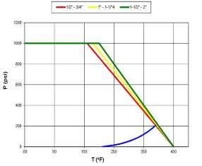
Dimensions inches
Pressure-temperature chart
Features:
• Dual sealing system allows valve to be operated in either direction making installation easier
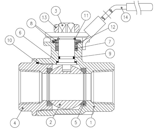
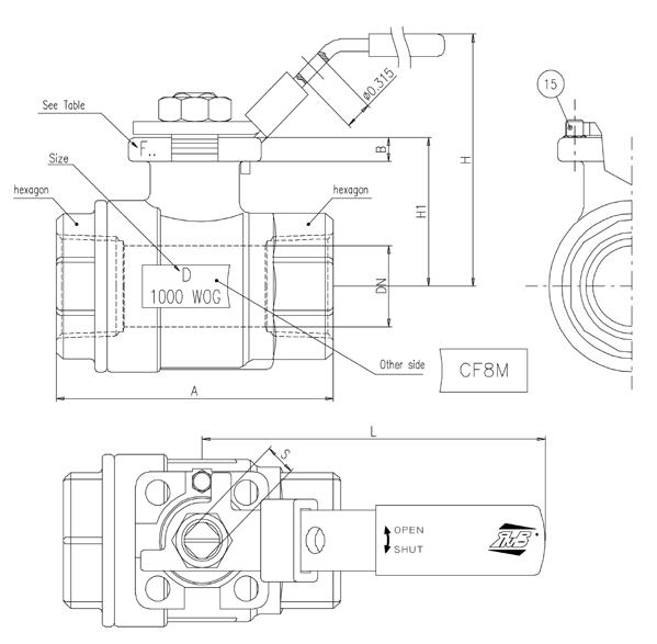
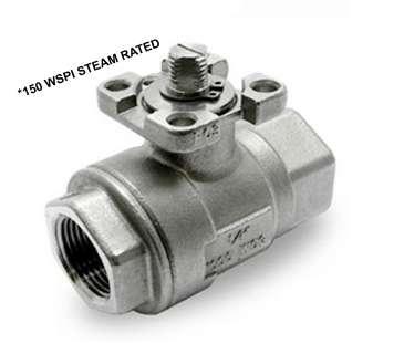
• Silicone-free lubricant on all seals
• NACE compliance MR-01-75
Pressure drop chart
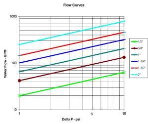
Page 56 R VALVES & ACTUATORS
1/2" - 2" ISO 5211 Part description Qty Material 1 Body 1 A351-CF8M 2 Ball 1 A351-CF8M 3 Stem 1 AISI316 4 Cap 1 A351-CF8M 5 Seat 2 RTFE 6 Seat 1 RTFE 7 Packing TFE 8 Bellville 2 SK5 9 O-Ring 1 FPM 10 Gasket 1 RTFE 11 Snapring 1 AISI304 12 Follower 1 AISI316 13 Nut 1 AISI304 14 Lockable handle 1 A240 SS304 15 Stop pin 1 AISI304 Code 134D41 134E41 134F41 134G41 134H41 134I41 D 1/2” 3/4” 1” 1 1/4” 1 1/2” 2” DN 0.56 0.81 1 1.25 1.5 1.97 H1 1.40 1.56 1.84 2 2.3 2.8 A 2.60 2.99 3.54 3.94 4.41 5 B 0.26 0.28 0.319 0.319 0.319 0.382 S 0.35 0.35 0.43 0.43 0.43 0.55 Flange connection DIN ISO 5211 DIN 3337 F03 F03 F04/F05 F04/F05 F04/F05 F05 Code 134D41L* 134E41L* 134F41L* 134G41L* 134H41L* 134I41L* L 4.40 4.40 5.87 5.87 5.87 7.5 H 2.50 2.66 3.14 3.3 3.6 4.5
*Ball valves
with stainless steel lock lever handle
fitted
Torque for actuator sizing in-lb
Water flow ratings
Page 57 R VALVES & ACTUATORS Size 1/2” 3/4” 1” 1 1/4” 1 1/2” 2” CV 20 42 65 101 145 250
Delta P --> 0 - 200 PSI Valve Size to open to close 1/2” 49 41 3/4” 78 59 1” 123 66 1 1/4” 156 109 1 1/2” 250 144 2” 317 211 Valve 134D41 134E41 134F41 134G41 134H41 134I41 Valve Size 1/2” 3/4” 1” 1 1/4” 1 1/2” 2” Double acting pneumatic actuator Actuator EA4-1 EA4-2 EA4-3 Actuation kit EA1D134D41 EA2D134E41 EA3D134F41 EA3D134G41 EA3D134H41 EA3D134I41 120 VAC, On/Off Actuator ET-1 ET-2 ET-3 Actuation kit ET1B134D41 ET1B134E41 ET2B134F41 ET2B134G41 ET2B134H41 ET3B134I41 120 VAC, On/Off Actuator CT-1 CT-3 CT-4 Actuation kit CT1BAN1134D41 CT1BAN1134E41 CT3BCM2134F41 CT3BCM2134G41 CT4ICM2134H41 CT4ICM2134I41 Spring return pneumatic actuator Actuator EA4-2 EA4-3 EA4-4 Actuation kit EA2R134D41 EA2R134E41 EA3R134F41 EA3R134G41 EA3R134H41 EA4R134I41 24 VAC, On/Off Actuator ET-1 ET-2 ET-3 Actuation kit ET1C134D41 ET1C134E41 ET2C134F41 ET2C134G41 ET2C134H41 ET3C134I41 24 VAC, On/Off Actuator CT-1 CT-3 CT-4 Actuation kit CT1CAN1134D41 CT1CAN1134E41 CT3CCM2134F41 CT3CCM2134G41 CT4LCM2134H41 CT4LCM2134I41 ET electric actuator EA pneumatic actuator CT electric actuator note for code: All the selection are made for delta P 0 - 200 PSI
s.135 stainless steel
2" - 3" - 4" ANSI B16.5 flange, ISO 5211
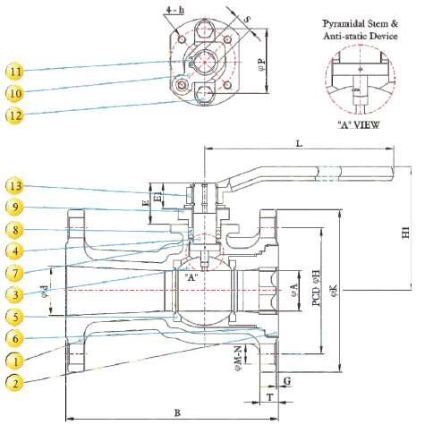
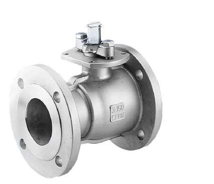
Technical data:
Working Pressure: General use: 750 PSI (see chart on reverse) | 275 PSI for ASME 150 CF8M (see chart on reverse) | Steam rating: 150 PSI WSP

Working Temperature: -50°F/+475°F
Threads: ANSI B16.5, B16.10 and B16.34 full compliance
Dimensions inches
Pressure-temperature chart
• Anti-static device
• Locking device
• Long cycle life
• Test standard: API 598
• API 607 4th edition fire safe approval
• Vacuum service to 29” Hg
*ME-PTFE is Moleculary Enhanced PTFE
Page 58 R VALVES & ACTUATORS
Part description Qty Material 1 Body 1 ASTM A351-CF8M 2 Cap 1 ASTM A351-CF8M 3 Ball 1 ASTM A351-CF8M 4 Stem 1 ASTM A276 Gr.316 5 Seat 2 ME-PTFE* 6 Gasket 1 ME-PTFE* 7 Thrust washer 1 ME-PTFE* 8 Packing 1 ME-PTFE* 9 Gland 1 ASTM A351-CF8 10 Stopper 1 SS304 11 Snap ring 2 SS304 12 Gland bolt 2 ASTM A193 Gr.B8 13 Handle 1 ASTM A536 Gr.65-45-12 Features: Code 135IF0 135MF0 135NF0 Size 2” 3” 4” A 1.50 2.56 3.15 B 7.0 8.0 9.0 E 1.65 2.20 2.20 E1 1.02 1.44 1.44 d 1.97 3.15 3.94 G 0.06 0.06 0.06 H 4.75 6.00 7.50 K 6.00 7.50 9.00 T 0.62 0.75 0.94 M 0.75 0.75 0.75 N 4 4 8 P 2.76 4.02 4.02 S 0.67 0.87 0.87 L 9.13 12.87 12.87 H1 4.96 5.98 6.30 h M8*P1.25 M10*P1.5 M10*P1.5
Torque
Valve torque can vary according to operating frequency, temperatre and friction characteristics of the media. If media has more or less friction than water, multiply torque by the following factors.
Page 59 R VALVES & ACTUATORS Size 2” 3” 4” CV 170 430 565
flow ratings
for actuator sizing in-lb
Water
Torque
correction factors
Lubricating oils or liquids 0.8 Dry gases, natural gas 1.5 Slurries or liquids bearing abrasive particles 1.5 to 2.5 Delta P --> Valve torque Valve Size to open to close 2" 376.15 376.15 3" 678.9 678.9 4” 909 909 Valve 135IF0 135MF0 135NF0 Valve Size 2” 3” 4” Double acting pneumatic actuator Actuator EA4-3 EA4-4 EA4-5 Actuation kit EA3D135IF0 EA4D135MF0 EA5D135NF0 120 VAC, On/Off Actuator ET-3 ET-4 ET-5 Actuation kit ET3B135IF0 ET4B135MF0 ET5B135NF0 Spring return pneumatic actuator Actuator EA4-6 EA4-7 Actuation kit EA6R135IF0 EA7R135MF0 EA7R135NF0 24 VAC, On/Off Actuator ET-3 ET-4 ET-5 Actuation kit ET3C135IF0 ET4C135MF0 ET5C135NF0 ET electric actuator EA pneumatic actuator
s.136 stainless steel
6" - 8" ANSI B16.5 flange, ISO 5211
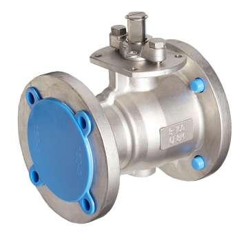
Technical data:
Working Pressure: General use: 750 PSI (see chart on reverse) | 275 PSI for ASME 150 CF8M (see chart on reverse) | Steam rating: 150 PSI WSP
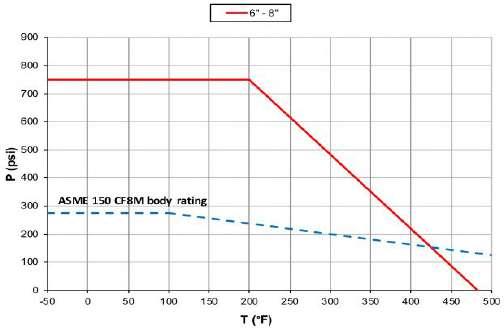
Working Temperature: -50°F/+475°F
Threads: ANSI B16.5, B16.10 and B16.34 full compliance
Dimensions inches
Pressure-temperature chart
• API 607 4th edition fire safe approval
• Vacuum service to 29” Hg
• Locking device
• Long cycle life
• Test standard: API 598
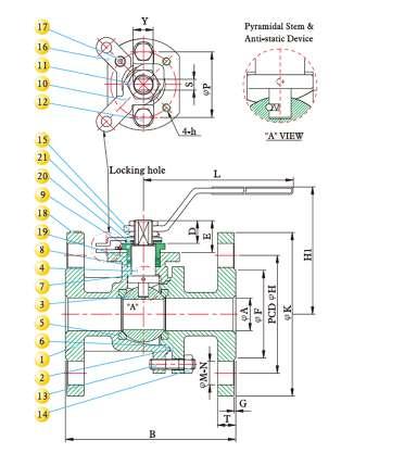
• Anti-static device
*ME-PTFE is Moleculary Enhanced PTFE
Page 60 R VALVES & ACTUATORS
Part description Qty Material 1 Body 1 ASTM A351-CF8M 2 Cap 1 ASTM A351-CF8M 3 Ball 1 ASTM A351-CF8M 4 Stem 1 ASTM A276 Gr. 316 5 Seat 2 ME-PTFE* 6 Gasket 1 GRAFOIL 7 Thrust washer 1 ME-PTFE* 8 Packing 1 GRAFOIL 9 Gland 1 ASTM A351- Gr. CF8 10 Stopper 1 SS304 11 Handle nut 2 SS304 12 Gland bolt 2 ASTM A193 Gr.B8 13 Stud bolt - Qty 4-10 ASTM A193 Gr.B8 14 Set nut - Qty 4-10 ASTM A194 Gr. 8 15 Handle 1 SS304 16 Locking plate 1 SS304 17 Set Bolt 2 SS304 18 Name plate 1 SS304 19 Ring 1 SS304 20 Bearing 1 NYLON 21 Lock washer 1 SS304 Features: Code 136PF0 136QF0 Size 6” 8” A 5.91 7.87 B 15.50 18.00 E 2.65 2.86 E1 8.50 10.62 D 1.48 1.88 G 0.06 0.06 H 9.50 11.75 K 11.00 13.50 T 1.00 1.12 M 0.88 0.88 N 8 8 P 4.92 5.51 S 0.79 1.30 L 40.63 12.87 H1 10.37 12.00 h M12x1.75 M16x2.0 CV (GPM) 5100 9400
Valve torque can vary according to operating frequency, temperatre and friction characteristics of the media. If media has more or less friction than water, multiply torque by the following factors.
Page 61 R VALVES & ACTUATORS Size 6” 8” CV 5100 9400 Water flow ratings Torque for actuator sizing in-lb
correction factors
Torque
Lubricating oils or liquids 0.8 Dry gases, natural gas 1.5 Slurries or liquids bearing abrasive particles 1.5 to 2.5 Delta P --> Valve torque Valve Size to open to close 6" 2531.4 2531.4 8" 5753 5753 Valve 136PF0 136QF0 Valve Size 6" 8" Double acting pneumatic actuator Actuator EA4-7 EA4-9 Actuation kit EA7D136PF0 EA9D136QF0 120 VAC, On/Off Actuator ET-7 ET-9 Actuation kit ET7B136PF0 ET9B136QF0 Spring return pneumatic actuator Actuator EA4-10 EA4-12 Actuation kit EA10R136PF0 EA12R136QF0 24 VAC, On/Off Actuator ET-7 ET-9 Actuation kit ET7C136PF0 ET9C136QF0 ET electric actuator EA pneumatic actuator
ALL RIGHTS RESERVED | COPYRIGHT© R UB, Inc. 2023

R UB, Inc. endeavors to provide comprehensive information about the installation, maintenance and operation of its products. For more details or clarification, please contact us. R UB, Inc. reserves the right to change or modify product design, construction, specifications, materials or the information herein without prior notice and without incurring any obligation to make such changes and modifications on products previously or subsequently sold. Content of this document is proprietary to R UB, Inc. and it may not be copied in part or in whole without prior written authorization. Recommendations on application design and material selection are based on available technical data and are offered as suggestions only. Each user should make his/her own tests to determine the suitability for his/her own particular use. R UB, Inc. gives no express or implied warranties concerning the form, fit, or function of a product in any application. R UB, Inc. does not accept liability for errors or omissions. Any undated reference to a code or standard shall be interpreted as referring to the latest edition. R UB and triangles are all registered trademarks of our property. Other logos or trademarks are property of respective owners. For complete disclaimer: www.rubinc.com/disclaimer

Page 62 R VALVES & ACTUATORS
Page 63
RUB, Inc. 4401 Dean Lakes Blvd. - Shakopee, MN 55379-2715 (USA) Tel: +1 (952) 857 1114 - Fax: +1 (952) 857 1118 sales@rubinc.com - www.rubinc.com R VALVES & ACTUATORS XMK048US.03 - 02/2023

