PORTFOLIO.
BINDU MARINGANTI WADIYAR CENTRE FOR ARCHITECTURE
Phone: +919986576123
Email: bindumaringanti@gmail.com
D.O.B.: 10th May, 2000
Address: 3rd Main, Paramahamsa Road, Yadavagiri, Mysuru, Karnataka, India, 570002
Languages:
English
Telugu
Kannada
Hindi
My name is Bindu Maringanti.
A recently graduated student from Wadiyar Centre for Architecture, Mysuru, I’ve always viewed the design process to be paradoxical.
Liberating, yet at the same time, binding. Seemingly simple. yet at the same time, complex.

Through the five years I’ve spent in architecture school, I’ve tried to navigate through the paradox that the design process is, and found my passion and curiosity towards the profession to have grown.
This portfolio consists of selected projects I’ve worked on and explored through the course of five years.

CURRICULUM VITAE.
Education:
2004- 2016
Primary and Secondary Education
National Public School, Koramangala, Bangalore
Grade: 10 CGPA
2016- 2018
Pre- University City P.U. College, Jayanagar, Bangalore
Grade: 92%
2018- 2023
Bachelor in Architecture (B.Arch)
Wadiyar Centre for Architecture, Mysuru
Experience:
August 2022- January 2023
Internship at Studio Matter, Goa
- Entrusted with entire set of working drawings for mock up space of a commercial retail store. Involvement in design process from the beginning, making of presentation drawings of iterations of furniture and layouts to present to clients.
- Created CAD working drawings and Sketchup models for ongoing residential projects in Bihar and in Goa.
- Assigned work on background and support tasks on content and editorial projects that are undertaken by the firm, worked on administrative and office tasks that required me to assist the team or the directors.
Skills:
Software skills:
Drafting: AutoCAD Revit
Modelling: Sketchup Revit Rhino (basics)
Rendering: Enscape
V-ray
Lumion
Involvements: Assistant Editor Courtyard (A student- run college newsletter)
2019-2021
I was in charge of editing the articles we receive and had also written several articles for the newsletter.
I had also undertaken leadership positions during my involvement in the newsletter.
Head of poetry club
WCFA
2020-2021
I was involved in organising virtual open mics and club meets.
Post Production:
Adobe Photoshop
Adobe Indesign
Adobe Illustrator
Website Making: Wix
Google Workspace
Others:
Architectural writing and journalism
Photography
Hand drafting and sketching+ model making
Participation:
Zonasa Design Trophy (2020)
Involved in designing a bus terminal for an annual design competition.
Zonasa Journalism Trophy (2019)
CONTENT. anganwadi
5-14 15-26 27-32 33-38 39-46 47
as a kit of parts.
internship. co- working space. music institute.
a
01. 02. 03. 04. 05. 06.
sarkari hiriya prathamika shaale. conceptual work.
thesis project. a glimpse of projects worked on during internship. models of ideas.
anganwadi as a kit of parts.
a thesis project.
AIM AND INTENT
What is an Anganwadi?
These Centres are child care centres that are to provide for early childhood services that encompass health, nutrition and education in an integrated manner. On further research regarding what constitutes this scheme and on visits to existing AWCs and observations being made with regard to these, have found that on the ground level, the implementation does not completely fulfill what the scheme entails in terms of ‘holistic development of children’; this will be elaborated upon in more detail in the document.
My attempt to carrying out this exploration is to understand the existing scenario of AWCs in the city of Mysore in particular and propose small changes to the implementation of the already existing schemes and infrastructure regarding AWCs to make the path to the construction, usage and expansion of these Centres easier.
The aim is to explore how pre- primary education can become more easily accessible and easier to avail.
More specifically, the aim of the project is to look into various schemes concerning the construction of AWCs, observe the existing scenario and to pave a path to making the usage of these spaces easier and more comfortable.
GUIDE:
Shreyas Baindur
SITE LOCATION
Kumbarakoppal, Mysuru
DURATION
18 weeks
Total budget: 12 Lakhs
5 01.
Narrative deduced:


1. The bench provided to the scientist helps the scientist access the coats; Similarly, ECCE was also intended to make pre-primary education more accessible to a larger user group.
2. XXICDS was was discovered to be made of six elements; two of the elements were found to be expanding. Similarly, ICDS comprises of six services, and there is an overlap in services provided on one day of a month.
3. Upon observing that El.IM and El.HC are expanding, it was realised that these elements must be separated from the rest; similarly, on the day of the month when the services overlap, in an attempt to maximise the quality of the services
4. It was found that on separation of the two compounds, the initial compound is prone to gradually becoming redundant because of the lack of the mitochondria. Hence, combining the two on that particular day of the month becomes necessary thought of to be a good solution to enable the implementation of the services at the Anganwadi Centre to the best potential as opposed to having a more permanent infrastructure as this infrastructure is one which is shared by multiple institutions; where it functions as a temporary reading space. In this way, the funds required for the implementation of this infrastructure gets divided between multiple institutions.
6 Portfolio.
The Comic Series ‘Adventures of Scientist X’ was made in an attempt to draw parallels to the thesis project undertaken to the storyline of the comic.
Govt Schemes in question ECCE
Early Childhood Care and Education (ECCE) is a framework that refers to all care and education services provided for children below 6 years of age.
ICDS
Integrated Child Development Services is a scheme that falls under ECCE.
ICDS: Research regarding the 6 policies
The ICDS Scheme offers a package of six services as listed below:
1. Supplementary Nutrition


2. Pre-school non-formal education
3. Nutrition & health education
4. Immunization
5. Health check-up and
Objectives
The objectives of the project are to:
1. Design two modules for the construction of an Anganwadi:
a. Module A:
Module A will be a base structural module of an anganwadi.
b. Module B
Module B will be a mobile temporary infrastructure that works in tandem with a framed fixed structure.
2. To demonstrate how an ideal interaction between the two modules can happen on site, pave way for future construction of anganwadis.
provided, the aim was to dividethe infrastructure of the services provided
6. Referral services necessary for all the elements to function to the fullest of the potential. Similarly, a temporary infrastructure in which health check-ups and immunization takes place was institutions; on days when health check-ups and immunization occurs, it halts at the Anganwadi Centre, and on other days, it is taken to nearby GovernmentSchools
3. To demonstrate how module B can attach itself to existing Anganwadis and function as a temporary infrastructure+community space.
7
AWC at Vijayanagar: The Garadi Mane AWC
The aim of selecting a site with an existing anganwadi was to demonstrate how the mobile component can plug- in to the existing AWC and become a temporary infrastructure for Immunization and Health Check- Up to take place.
Site

The city of Mysuru. Three sites were selected, out of which two of them (site at Temple Road and site at Vijayanagar) had existing Anganwadis and were selected for demonstration of design of how the mobile component designed can plug into the existing Anganwadi and serve as a temporary infrastructure


The site at Kumbarakoppal has been selected in an attempt to demonstrate the functioning of the structural module and the mobile component together. The site so selected already has an existing AWC present; it, however, has been facing certain structural issues due to poor maintenance. The design demonstration aims to redesign the existing AWC on the site, and use the method of construction proposed through the design proposal.
AWC on Temple Road
The aim of selecting a site with an existing anganwadi was to demonstrate how the mobile component can plug- in to the existing AWC and become a temporary infrastructure for Immunization and Health Check- Up to take place.
Site at Kumbarakoppal:
A site for design demonstration of functioning of the structural module and the mobile component

8 Portfolio.
24.5M
23.5M
13M
18.5M
Stakeholders
When do they use the space?


Anganwadi Worker Children between 0-6 years
Pregnant+ lactating women Adolescent girls
Primary Health Care Worker
Other members of community
Timelines:
Overlap of stakeholders at Anganwadi Centres


MondaySaturday (9AM-4PM)
MondaySaturday (9AM-4PM)
2-3 days of a month
A. On a Regular Day
1 day of a month
Very brief visits
B. Ration Day
Observations: Timelines were drawn up on different days based on observations at a particular Anganwadi Centre and it was found that due to the overlap in services on one particular day in a month, the space at the Anganwadi Centre was not sufficient for all the services to be provided to the best of the quality.
C. Health Check Up
D. ECCE Day
9
9AM 12PM 10PM 1PM 3PM 4PM
The Structural Module: Joinery details to attach multiple modules to each other and between footing and members
The Structural Module: Joinery details between the two members
The structural module has been designed in a way such that the joineries were worked out in a way which allowed the individual pieces could be disassembled and assembled easily. This gave the AWC so formed a more temporary nature; this is beneficial as it allows for expansion of the AWC Centre. Expansion of AWC Centres come into picture as the population in neighbourhoods are constantly increasing; people migrating into the neighbourhood is one possibility.
10 Portfolio. 3000 3000
2" X 2" BOX SECTION-
OUTER SKIN
PIVOT HINGE

10MM THICK PLYWOOD
2" X 2" BOX SECTION
10MM THICK PLYWOOD SHELVES
Materials used for Mobile Component
The major materials used for the mobile component include:
1. MS 4” X 4” box sections


2. Plywood skin and shelves
MOBILE BASE FOR MODULE
MILD STEEL WASHER

11
3. MS washers
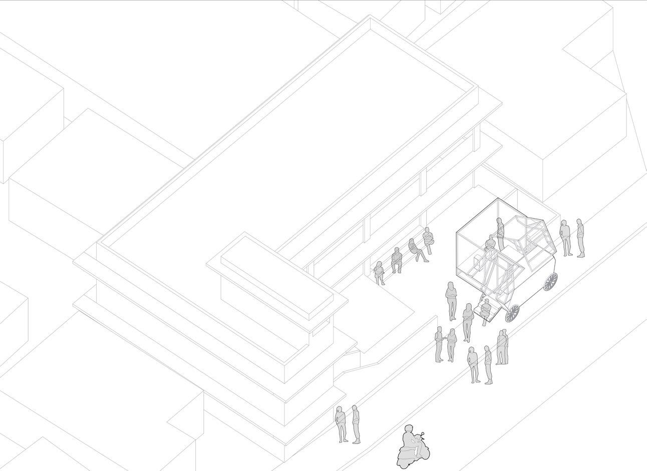
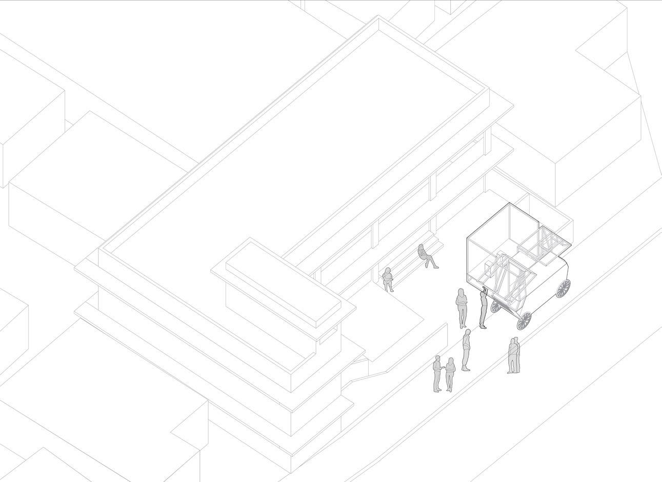
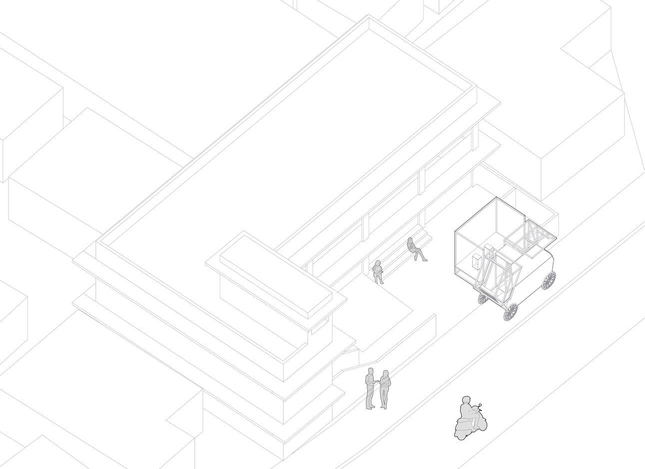
View of Mobile Component attached to bike
Section through Mobile Component
Demonstration at existing Anganwadi Centres and Govt. Schools
The adjoining graphics were made to demonstrate how the mobile component functions, opens up and is used at existing Anganwadi Centres and Government Schools.


12 Portfolio.
At Government School
At Garadi Mane Anganwadi Centre At Temple Road Anganwadi Centre
Ground Floor Plan (At +1M)


Design of demonstration of functioning of structural module and mobile component
The next step in the design process was to demonstrate how the structural module and the mobile component fuction together. The first step to designing on the selected site was the assumption that the existing AWC was to be reconstructed. Through plans and sections, it was worked out how the two components could function together.
13
Section BB
Section AA
3D representation of demonstration
internship.
a glimpse of projects worked on during internship. Studio Matter, Goa
During the internship period, was entrusted with entire set of working drawings for mock up space of a commercial retail store. Involvement in design process from the beginning, making of presentation drawings of iterations of furniture and layouts to present to clients.
have Created CAD drawings and Sketchup models for ongoing residential projects in Goa and in Bihar.
WORKED PREDOMINANTLY UNDER:
Ruturaj Parikh
Aliptha Reddy Govindu
Rishiraj Sarkar
DURATION
24 weeks
15 02.
ROAD MID
ROAD WIDENING LINE
PLINTH OF EXISTING HOUSE
Drawn: Bindu Maringanti
Checked: Aliptha Govindu
For: Issue
LEGEND:
Moira Courtyard House
Location: Moira, Goa
Typology: Residential
Moira Courtyard House is a residential project located in Moira, Goa.
The program involved the design of a yoga pavilion and a residential space within a three bedroom module.
The site is located in the midst of a lush green vegetated area, which provides the opportunity to capture multiple beautiful views from within the house; the opportunity to heighten the connect between the outside to the inside becomes evident
C1- C21 are columns provided engineer
Revision Number: 0
Scale: 1:150 | A3 Colour
All dimensions in MM. To be read, not measured.
Drawing:
GROUND FLOOR LINEOUT PLAN
Drawing No.: A001(a.1)
16 Portfolio. MATTER. studio@matter.co.in
Moira II Project:
1 ROAD MID ROAD WIDENING LINE 13760 4460 4800 4500 17960 2000 5485 2715 2800 4960 NEW SETBACK LINE 13760 2030 2470 2800 2000 4460 17960 2000 3100 5100 2800 4960 2 X 3 4 5 ROAD WIDENING LINE D P A B A E B X 1 2 Y 3 4 5 Y P D C C SITE BOUNDARY AS PER SURVEY
C1 C2 C3 C4 C5 C6 C7 C8 C9 C10 C11 C12 C13 C14 C15 C16 C17 C18 C19 C20 C21 E SC1 SC2 SC3 SC4 SC5 SC6 SC7 SC8 40 470 424 994 150 150 150
01. 04 October 2022 1330 8960 P1 P4 P2 3715 P3 1770 5000 3000 5000 3000 4455 2100
NOTE:
4370 11340 9550 9070 POINT TO BE DETERMINED ON SITE
Lineout Plan
Staircase Detail
MATTER. STAIRCASE
Staircase Plan: Ground Floor
Staircase Plan: First Floor
17 FFL +3060
SECTION AA' Drawing: 0M 0.25M 1M 0.5M Scale: 1:25 A3 Monochrome To be read, not measured. Revision Number: 0 Moira Courtyard House Project: studio@matter.co.in Drawn: Bindu Maringanti Checked: Aliptha Govindu For: Issue 1 2 3 4 5 6 7 8 9 10 11 12 13 14 15 16 17 18 FFL +1530 UFL -150 UFL +0 FFL +0 1530 1530 3060 UFL +1530 UFL +3060 4 5 900 500 FINISHED FLOOR LINE 150 CINDER BACKFILL 170 300 900 400 230 BALUSTRADE 150 TO MATCH SOFFIT 4 5 150 136 200 150 50 1050 4960 900 W5 D5 W10 W10 D5 900 Drawing No.:A004(a.4) 01.17 November 2022 NOTES: 1. All dimensions are in mm 2. For reinforcement details, refer to structural drawing STAIRCASE PLANS Drawing: Scale: 1:25 A3 Monochrome To be read, not measured. Revision Number: 0 Moira Courtyard House Project: Drawn: Bindu Maringanti Checked: Aliptha Govindu For: Issue UP 4 5 4 5 C C D D 2000 4960 W5 FFL +0 1000 300 50 A A' 1050 FFL +1530 C10 D5 C15 C11 C16 1 2 4 6 9 10 11 12 13 14 15 16 17 RCC LINE STAIRCASE FINISH 4 5 4960 BALUSTRADE 1000 GROUND FLOOR PLAN FIRST 1050 Drawing No.:A003(a.3) 01.17 November 2022 NOTES: 1. All dimensions are in mm 2. For reinforcement details, refer to structural drawing MATTER. STAIRCASE PLANS Drawing: 0M 0.25M 1M 0.5M Scale: 1:25 A3 Monochrome To be read, not measured. Revision Number: 0 Moira Courtyard House Project: studio@matter.co.in Drawn: Bindu Maringanti Checked: Aliptha Govindu For: Issue UP 4 5 4 5 C C D D 2000 4960 W5 FFL +0 1000 300 50 A A' 1050 FFL +1530 C10 D5 C15 C11 C16 10 11 12 13 14 15 16 17 RCC LINE STAIRCASE FINISH DN 4 5 4 5 C C D D 2000 4960 W10 FFL +3060 1000 300 50 A A' 1050 FFL +1530 C10 D5 C15 C11 C16 1 2 4 5 6 7 8 9 10 11 12 13 14 15 16 17 RCC LINE STAIRCASE FINISH BALUSTRADE SOFFIT W10 18 BALUSTRADE 1000 1000 1000 GROUND FLOOR PLAN FIRST FLOOR PLAN 100 1050 Drawing No.:A003(a.3) 01.17 November 2022 NOTES: 1. All dimensions are in mm 2. For reinforcement details, refer to structural drawing
THIS WALL HAS MOVED BY 100MM
Ground Floor Masonry Plan
NOTES:
1. All dimensions are finish to finish.
2. All dimensions are in mm
3. All walls are 230mm thick unless specified otherwise
Drawing: Drawn: Bindu Maringanti Checked: Aliptha Govindu For: Issue
GROUND FLOOR MASONRY PLAN
18 Portfolio. 1 13760 4460 4800 4500 17960 2000 2715 2800 4960 13760 2030 2470 2800 2000 4460 17960 2000 3100 5100 2800 4960 2 X 3 4 5 D P A E B A E B X 1 2 Y 3 4 5 Y P D C C 12770 4500 3450 3380 2000 1100 2270 2515 1800 3180 1465 600 340 900 4810 965 965 3470 10170 600 800 600 450 5485 D1 D4 D4 D2 D3 D3 D3 D3 W4 V1 D6 D8 W5 D5 D6 UP SITE BOUNDARY AS PER SURVEY 4000 C1 C2 C3 C4 C5 C6 C7 C8 C9 C10 C11 C12 C13 C14 C15 C16 C17 C18 C19 C20 C21 FFL +0
0M 1M 4M 2M studio@matter.co.in FFL -150 UFL -300 LVL -450
PLAN Drawing: Drawn: Bindu Maringanti Checked: Aliptha Govindu For: Issue NOTES: 1. All dimensions are finish to finish. 2. All dimensions are in mm 3. All walls are 230mm thick unless specified otherwise Doors- Ground Floor Type Size Sill Lintel Nos. D1 4570 x 2460 0 2460 1 D2 2400 X 2460 0 2460 1 D3 900 X 2460 0 2460 4 D4 1050 X 2460 0 2460 2 D5 1200 X 2460 0 2460 2 D6 3600 X 2460 0 2460 2 D7 3000 X 2460 0 2460 2 D8 2400 X 2460 0 2460 2 Ventilation Type Size Sill Lintel Nos. V1 3180 X 660 1800 2460 1 V2 630 X 660 1800 2460 1 Moira II Door - Window Schedule Windows Ground Floor Type Size Sill Lintel Nos. W1 4000 X 2460 0 2460 1 W2 1800 X 1260 1200 2460 1 W3 3420 X 2460 0 2460 1 W4 3595 X 1260 1200 2460 1 W5 2000 X 2460 0 2460 1 W6 2800 X 660 1800 2460 1 W7 1620 X 660 1800 2460 1 W8 450 X 450 1250 1700 1 Scale: 1:100 | A3 Monochrome To be read, not measured. Revision Number: 01 LEGENDS: Moira Courtyard House Project: 700
MID 2855 1700 2340 340 115 115 115 115 4270 Drawing No.:A007(a.7) V2 W2 1010 565 960 875 115 730 500 400 925 730 730 800 115 115 2240 600 630 1000 D7 D7 480 115 565 D5 1315 D8 W3 W1 W7 W8 580 905 1505 W6 01. 21 December 2022 B B' A A' 485 230 500 300 SLAB TOP +3060 BBL +2460 UFL +0 4 4 5 5 SLAB TOP +3060 BBL +2460 UFL +0 E E SPOT SECTION AA' SPOT SECTION BB' 100 500 100 D7 V1 V2 9000 2400 3600 2400 3600 450 1200 900 900 900 900 1800 3000 3420 1050 2400 1000 3000 1200 1050 4570 1620 1050 2800 02. 23 December 2022 MASONRY UPTO 1530MM HIGH TO MATCH THE STAIRCASE LANDING THIS WALL HAS MOVED BY 100MM 3595 1 13760 4460 4800 4500 13760 2030 2470 2800 2000 4460 17960 2000 3100 5100 2800 4960 2 X 3 4 5 D P A E B A E B X Y P D C C 12770 4500 3450 3380 2000 1100 2270 2515 1800 3180 1465 600 340 900 4810 965 965 3470 10170 600 800 600 450 D1 D4 D4 D2 D3 D3 D3 D3 W4 V1 D6 D8 W5 D5 D6 UP 4000 C1 C2 C3 C4 C5 C6 C7 C8 C9 C10 C11 C12 C13 C14 C15 C16 C17 C18 C19 C20 C21 FFL +0 FFL -150 UFL -300 LVL -450
MATTER. N
EXISTING ROAD GROUND FLOOR MASONRY
EXISTING ROAD ROAD
Doors- Ground Floor Type Size Sill Lintel Nos. D1 4570 x 2460 0 2460 1 D2 2400 X 2460 0 2460 1 D3 900 X 2460 0 2460 4 D4 1050 X 2460 0 2460 2 D5 1200 X 2460 0 2460 2 D6 3600 X 2460 0 2460 2 D7 3000 X 2460 0 2460 2 D8 2400 X 2460 0 2460 2 Ventilation Type Size Sill Lintel Nos. V1 3180 X 660 1800 2460 1 V2 630 X 660 1800 2460 1 Moira II Door - Window Schedule Windows - Ground Floor Type Size Sill Lintel Nos. W1 4000 X 2460 0 2460 1 W2 1800 X 1260 1200 2460 1 W3 3420 X 2460 0 2460 1 W4 3595 X 1260 1200 2460 1 W5 2000 X 2460 0 2460 1 W6 2800 X 660 1800 2460 1 W7 1620 X 660 1800 2460 1 W8 450 X 450 1250 1700 1 Scale: 1:100 | A3 Monochrome To be read, not measured. Revision Number: 01 LEGENDS: Moira Courtyard House Project: 700 2855 1700 2340 340 115 115 115 115 4270 Drawing No.:A007(a.7) V2 W2 1010 565 960 875 115 730 500 400 925 730 730 800 115 115 2240 600 630 1000 D7 D7 480 115 565 D5 1315 D8 W3 W1 W7 W8 580 905 1505 W6 01. 21 December 2022 B B' A A' 485 230 300 4 4 V2 9000 2400 3600 2400 3600 450 1200 900 900 900 900 1800 3000 3420 1050 2400 1000 3000 1200 1050 4570 1620 1050 2800 02. 23 December 2022 MASONRY UPTO 1530MM HIGH TO MATCH THE STAIRCASE LANDING
3595
MATTER.
Ground Floor Electrical Layout
First Floor Electrical Layout
19 SB Wall point Ceiling Fan Light Point @ Ceiling WIFI Router Exhaust Fan Foot Light LEGEND Switch Board GROUND FLOOR ELECTRICAL LAYOUT Drawn: Bindu Maringanti Checked: Aliptha Govindu For: Information NOTES: 1. All dimensions are in mm Scale: 1:75 A3 Colour To be read, not measured. Number: 00 Moira Courtyard House Project: No.:A013(e.1)
N 0M 1M 4M 2M studio@matter.co.in 1 2 X 3 4 5 D P A E B A E B X 1 2 Y 3 4 5 Y P D C C SB18 AC IDU CCTV AC IDU AC ODU SB1 SB2 SB3 Eq Eq SB4 SB5 SB13 SB14 SB15 SB16 SB17 SB19 1000 1000 1000 1000 600 SB22 SB21 SB20 SB23 SB24 SB25 SB27 SB28 1000 1000 1000 1000 1000 1000 1000 1000 1000 1000 1000 1000 1000 1000 1000 1000 1000 1000 1000 1000 1000 Eq Eq SB6 SB11 600 600 1000 1000 1000 1000 1000 1000 1000 1000 1000 1000 1000 1000 1000 Eq 150 Eq 230 1280 1200 600 150 150 300 400 400 Eq Eq 1110 150 Eq 200 300 Eq Eq Eq Eq TV All measurements from FFL All measurements to the center of switch board NOTES: WP 1 @ 2200 mm from FFL WP 2 @ 2450 mm from FFL WP 3 @ 2700 mm from FFL WP 4 @ 1950 mm from FFL WP2 WP2 WP4 WP2 WP1 WP4 WP2 WP2 WP3 WP3 FL FL 1200 1200 750 AC Indoor Unit AC ODU AC Outdoor Unit Distribution Board FL @ 300 mm from FFL MB Metre Board FL FL FL FL Eq Eq FL FL FL FL FL FL FL FL FL FL CCTV Monitor FL Eq Eq Eq Eq Eq Eq Eq Eq CCTV TV TV B Door bell MB Eq Eq Eq Eq Eq Eq Eq Eq Eq Eq Eq Eq Eq Eq Eq 1000 Eq Eq Eq Eq Eq Eq Eq Eq Eq Eq Eq Eq Eq Eq Eq Telephone Outlet Eq Eq CCTV Camera @2450 Eq Eq 600 Eq Eq SB7 Eq Eq Eq Eq Eq Eq Eq Eq SB9 SB12 Eq Eq WP2 WP2 WP2 WP2 150 515 485 870 250 Eq Eq Eq WP2 Eq Eq SB26 600 WP4 WP2 WP3 WP3 WP2 WP1 WP3 WP2 WP2 WP2 WP1 230 1930 SB8 SB10 504 982 1440 Doorbell speaker @2450 FL FL FL 225 85 SB x Wall point Ceiling Fan Light Point @ Ceiling WIFI Router Exhaust Fan Foot Light LEGEND Switch Board
FLOOR
LAYOUT Drawing: Drawn: Bindu Maringanti Checked: Aliptha Govindu For: Information NOTES: 1. All dimensions are in mm Scale: 1:75 A3 Colour To be read, not measured. Revision Number: 00 Moira Courtyard House Project: Drawing No.:A013(e.1) MATTER. 0M 1M 1 2 X 3 4 5 D P A E B A E B X 1 2 Y 3 4 5 Y P D C C SB18 AC IDU CCTV AC IDU AC ODU SB1 SB2 SB3 Eq Eq SB4 SB5 SB13 SB14 SB15 SB16 SB17 SB19 1000 1000 1000 1000 600 SB22 SB21 SB20 SB23 SB24 SB25 SB27 SB28 1000 1000 1000 1000 1000 1000 1000 1000 1000 1000 1000 1000 1000 1000 1000 1000 1000 1000 1000 1000 1000 Eq Eq SB6 SB11 600 600 1000 1000 1000 1000 1000 1000 1000 1000 1000 1000 1000 1000 1000 Eq 150 Eq 230 1280 1200 600 150 150 300 400 400 Eq Eq 1110 150 Eq 200 300 Eq Eq Eq Eq TV All measurements from FFL All measurements to the center of switch board NOTES: WP 1 @ 2200 mm from FFL WP 2 @ 2450 mm from FFL WP 3 @ 2700 mm from FFL WP 4 @ 1950 mm from FFL WP2 WP2 WP4 WP2 WP1 WP4 WP2 WP2 WP3 WP3 FL FL 1200 1200 750 AC Indoor Unit AC ODU AC Outdoor Unit Distribution Board FL @ 300 mm from FFL MB Metre Board FL FL FL FL Eq Eq FL FL FL FL FL FL FL FL FL FL CCTV Monitor FL Eq Eq Eq Eq Eq Eq Eq Eq CCTV TV TV B Door bell MB Eq Eq Eq Eq Eq Eq Eq Eq Eq Eq Eq Eq Eq Eq Eq 1000 Eq Eq Eq Eq Eq Eq Eq Eq Eq Eq Eq Eq B Eq Eq Eq Telephone Outlet Eq Eq CCTV Camera @2450 Eq Eq 600 Eq Eq SB7 Eq Eq Eq Eq Eq Eq Eq Eq SB9 SB12 Eq Eq WP2 WP2 WP2 WP2 150 515 485 870 250 Eq Eq Eq WP2 Eq Eq SB26 600 WP4 WP2 WP3 WP3 WP2 WP1 WP3 WP2 WP2 WP2 WP1 230 1930 SB8 SB10 504 982 1440 Doorbell speaker @2450 FL FL FL 225 85 GROUND FLOOR ELECTRICAL LAYOUT Drawing: Drawn: Bindu Maringanti Checked: Aliptha Govindu For: Issue NOTES: 1. All dimensions are in mm Scale: 1:75 A3 Colour To be read, not measured. Revision Number: 00 LEGENDS: Moira Courtyard House Project: Drawing No.:A014(a.14) MATTER. N 0M 1M 2M studio@matter.co.in D P A E B A E B 1 2 3 4 5 D 1 2 X 3 4 5 C C X P AC IDU AC ODU AC IDU AC ODU SB32 AC IDU 1000 1000 1000 1000 1000 1000 1000 1000 1000 1000 1000 1000 1000 1000 1000 1000 1000 1000 882 1000 1000 1000 1000 1000 750 1400 eq eq eq eq 1050 SB27 SB28 SB26 SB29 SB30 SB31 SB33 SB34 SB35 SB36 SB37 150 600 1200 1200 2250 1200 300 300 750 2000 1350 1400 150 600 300 150 SB x Wall point on beam Ceiling Fan Light Point @ Ceiling WIFI Router Exhaust Fan Wall point LEGEND Switch Board AC
GROUND
ELECTRICAL
A clothing retail store for Tata
Location of mock-up space : Mumbai
Typology: Retail
One of the projects that was worked on during the course of the internship period is an interior design project for a series of stores for a brand to be newly launched.
The initial stages of the project included working out mulitple iterations in order to achieve the perfect pieces of furniture and orientation.
I had the opportunity to participate in discussions with the clients and make designbased decisions.
20 Portfolio.
Section AA’
21 LAYOUT IN PLAN Drawn: Bindu Maringanti Checked: Aliptha Govindu For: Issue NOTES: 1. All dimensions are in feet unless specified otherwise Scale: 1:30 A3 Colour To be read, not measured. Number: 01 Samoh Project: No.:A001(a.1) MATTER. studio@matter.co.in 1' 01. 11 January 2023 02. 20 January 2023 A B C 8'-8" E 1'-6" 6" G 4' 1' D 7'-4" 3' 3'-6" 6'-3" A A' ELEVATION A Existing Column Existing Glass Partition Concrete Finish on Existing Tiling Concrete Finish on HDF Panel 10'-2" 28' Existing Wall Existing Wall JOSMO RYGA TABLE 1'-2" 19'-8" 30'-4" 1'-2" 10'-1" 3' 2'-3" 5'-3" 7'-3" 4'-7" 11'-3" H F SECTION AA' Drawing: Drawn: Bindu Maringanti Checked: Aliptha Govindu For: Issue NOTES: 1. All dimensions are in feet unless specified otherwise Scale: 1:30 A3 Colour To be read, not measured. Revision Number: 01 Samoh Project: Drawing No.:A004(a.4) MATTER. studio@matter.co.in 0 1' 2' 01. 11 January 2023 02. 20 January 2023 Concealed LED Light 2" DETAIL A Light Box Ceiling 9'-3" 6" 8'-2" Concrete Finish on HDF Panel Concrete Finish on Existing Tiling Concealed LED Light 1' Detail A Fabric U- Channel 18'-11" 6" Track for Spot Lights 6'-11 2 1' 6'-11 2 1' 1'-10" 1'-10" 2" 9" Existing Glass Partition SECTION AA' 9" Concrete Finish on HDF Panel Drawing: NOTES: 1. All dimensions are in feet unless specified otherwise Scale: 1:30 A3 Colour To be read, not measured. Revision Number: 01 Drawing No.:A003(a.3) MATTER. studio@matter.co.in 01. 11 January 2023 02. 20 January 2023 9'-3" 8'-2" 6" 6" 29'-3" 6" 1' 27'-3" 1' U - Channel Concealed LED Lighting Concealed LED Light Concrete Finish on HDF Panel 6" Existing Glass Partition 28' 10'-2" 1'-8" 8" 4' Backlit Samoh Branding Cut in Brass REFLECTED CEILING PLAN Drawing: Drawn: Bindu Maringanti Checked: Aliptha Govindu For: Issue NOTES: 1. All dimensions are in feet unless specified otherwise Scale: 1:30 A3 Colour To be read, not measured. Revision Number: 01 Samoh Project: Drawing No.:A002(a.1) MATTER. studio@matter.co.in 1' 2' 01. 11 January 2023 02. 20 January 2023 1' 6" 1' 6'-1 1' 6'-1 1' 1'-10" Stretch Ceiling Track for Spot Lights Concrete Finish on Ceiling Concrete Finish on False Ceiling Panel Existing AC Vent Existing AC Vent Concealed LED Light Existing Glass Partition 28' Existing Column Existing Wall Concrete Finish on HDF Panel 6" 2" 10" 10" 2" 6" 10" 2" Existing Wall 1'-2" 1'-2" 27'-3"
Layout in Plan Elevation Reflected Ceiling Plan
Furniture D
Brass Plate (25MM X 8MM)
Brass Pipe (25MM Dia.)
Plate (25MM X 8MM) Brass Plate
Concrete Finish on Plywood Pedestal
Brass Plate (25MM X 8MM)
Brass Plate (25MM X 8MM)
6" Brass Pipe Attached to Wall (19MM Dia.)
Brass Plate on Plywood Pedestal
Brass Pipe (25MM Dia.)
Furniture G
Brass Plate (25MM X 8MM)
Brass Pipe Attached to Wall (19MM Dia.)
Brass Plate (25MM X 8MM)
VIEW E
Brass Plate Concrete Finish on Plywood Pedestal
22 Portfolio. Revision Number: FURNITURE 'G' AND Drawing: Scale: 1:20 All dimensions otherwise To be read, LEGENDS: SAMOH Project: Drawn: Bindu Checked: Aliptha For: Issue Drawing No.: 01. 23 January 6" 2' Concrete Finish on Plywood Pedestal Brass Plate Brass Plate (25MM X 8MM) ELEVATION G PLAN G ISOMETRIC VIEW G 1'-2" Brass Plate on Plywood Pedestal Brass Plate (25MM X 8MM) Concrete Finish on Plywood Pedestal Brass Plate Brass Plate (25MM X 8MM) 1'-2" 8" Brass Pipe (25MM Dia.) Two Sided Mirror Two Sided Mirror 1'-6" Timber Table Top (38MM Thickness) Concrete Finish on Plywood Base Cork Base Y' Y Brass Pipe (25MM Dia.) 2'-4" 3' 3' Concrete Finish on Plywood Base Brass Pipe (25MM Dia.) Timber Table Top (38MM Thickness) 6'-6" ELEVATION H PLAN H PLAN H YY' ISOMETRIC VIEW H 2'-4" Timber Table Top (38MM Thickness) Brass Pipe (25MM Dia.) Concrete Finish on Plywood Base Eq Eq Eq Eq 6" 6' 1'-2" 8' Brass
5'-6" ELEVATION
ISOMETRIC
E
PLAN E
MATTER. 0 1' 2' studio@matter.co.in Revision Number: 00 FURNITURE DETAIL 'E' Drawing: Scale: 1:20 A3 Monochrome All dimensions in feet unless specified otherwise To be read, not measured. LEGENDS: SAMOH Project: Drawn: Bindu Maringanti Checked: Aliptha Govindu For: Issue Drawing No.: A007 (d.3) 01. 13 January 2023
6"
1'-2"
D PLAN D
MATTER. 0 1' 2' studio@matter.co.in Revision Number: 00 FURNITURE DETAIL 'D' Drawing: Scale: 1:20 A3 Monochrome All dimensions in feet unless specified otherwise To be read, not measured. LEGENDS: Drawn: Bindu Maringanti Checked: Aliptha Govindu For: Issue Drawing No.: A006 (d.2) 01. 13 January 2023 6' 5'-6" 6" 6' 1" 6' 2' Brass Pipe (25MM Dia.) Brass Plate (25MM X 8MM) Brass Plate (25MM X 8MM) Brass Pipe (25MM Dia.) Concrete Finish on Plywood Base 6" 1'-2" 1'-2" 2" Brass
Brass Pipe
Dia.) Concrete Finish on Plywood Base Brass Plate (25MM X 8MM) Brass Plate (25MM X 8MM) Brass Pipe (19MM Dia.) Eq Eq
ELEVATION
ISOMETRIC VIEW D
Plate (25MM X 8MM) Brass Pipe (25MM Dia.)
(19MM
Furniture E
Furniture H
FURNITURE DETAIL
MATTER.
23
0 1' 2' studio@matter.co.in Revision Number: 00
'I' Drawing: Scale: 1:20 A3 Monochrome All dimensions in feet unless specified otherwise To be read, not measured. LEGENDS: SAMOH Project: Drawn: Bindu Maringanti Checked: Aliptha Govindu For: Issue Drawing No.: A010 (d.6) 01. 23 January 2023 8' 6' 2'-8" 4" PLAN ELEVATION 1' 1' 4" Z' Z' 3' 4" 1' 2' 1' 6" 6" 1'-8" HDF 1'-4" HDF HDF SECTION ZZ' 1' 6' HDF Branding in Brass ISOMETRIC VIEW I 4" 4" 2' 2' 2' 6" 6" 1'-8" 3'-4" 3'-4" 1' 1' 4" 4" 1' 1' 1' 1' 1' 1' Drawer Drawer Cabinet 4" Drawer Drawer Cabinet 2'-6" Timber Table Top (38MM Thickness) Concrete Finish on Plywood Base Cork Base L' L Brass Pipe (25MM Dia.) 6'-4" 7' Revision FURNITURE 'J' Drawing: Scale: All dimensions otherwise To be LEGENDS: SAMOH Project: Drawn: Checked: For: Issue Drawing 01. 23 Brass Pipe (25MM Dia.) Timber Table Top (38MM Thickness) Concrete Finish on Plywood Base ELEVATION J PLAN J PLAN J LL' Timber Table Top (38MM Thickness) Brass Pipe (25MM Dia.) Concrete Finish on Plywood Base EXPLODED ISO J 7' 6'-4" 1'-10" 2'-6" 2'-7" 2'-7" 7" 7" 2'-7" 2'-7" 7" 7"
0 1' 2' studio@matter.co.in Revision Number: 00 FURNITURE DETAIL 'G' AND 'H' Drawing: Scale: 1:20 A3 Monochrome All dimensions in feet unless specified otherwise To be read, not measured. Drawing No.: A009 (d.5) 2' Concrete Finish on Plywood Pedestal Brass Plate ELEVATION G PLAN G ISOMETRIC VIEW G 1'-2" Concrete Finish on Plywood Pedestal 1'-6" Timber Table Top (38MM Thickness) Concrete Finish on Plywood Base Cork Base Y' Y Brass Pipe (25MM Dia.) 2'-4" 3' 3' Concrete Finish on Plywood Base Brass Pipe (25MM Dia.) Timber Table Top (38MM Thickness) ELEVATION H PLAN H PLAN H YY' ISOMETRIC VIEW H 2'-4" Timber Table Top (38MM Thickness) Brass Pipe (25MM Dia.) Concrete Finish on Plywood Base Eq Eq Eq Eq
MATTER.
Furniture I
Dalan House Extension
Location: Siwan, BIhar
Typology: Residential Dalan house extension is a residential project located in Siwan, Bihar. This Project mainly comprises of two parts:
1. Design and construction of an outhouse
2. Renovation of the existing Dalan house
The initial stages of construction of the Dalan outhouse consist of the following stages:
1. Excavation for footings of 100 X 100 steel columns
2. Excavation of plinth beam
3. Casting of footings and plinth beams
4. Backfilling of trenches
5. Positioning of steel plates for columns
6. Casting of columns
7. Bringing up the outer masonry walls up to half height
8. Casting of steel members (100 X 100 beams and 50 X 50 purlins)
9. Construction of masonry walls
24 Portfolio. 100 75 75 950 150 2400 900 LVL +0 50x50 MM BOX SECTION 900 A 1800 115MM THICK BRICK JALI WALL SOIL MATTER. SECTION AA' Drawing: 0 1M 4M 2M Scale: 1:50 | A3 Colour All dimensions in MM. To be read, not measured. Revision Number: 01 Project: studio@matter.co.in 400 B C A B C 100x100MM BOX SECTION 75MM PCC 250x250 RCC PLINTH BEAM MASONRY RAINWATER GUTTER (DETAIL A) 75MM FBS 550 725 300 597 D3 D9 B7 B16 A7 A16 100MM LOCAL SAND FILLING 3205 3500 3537 LVL +2500 LVL +3500 NOTES: All dimensions are in mm 100 MM THK PCC COPING ROOF FLASHING 1350 150 250MM THICK MASONRY WALL 100x100MM BOX SECTION 01. 03 October 2022 100 100 400 550 725 300 50x50 MM BOX SECTION 100x100MM BOX SECTION GI ZINC AL SHEET BENT TO PROFILE DETAIL AT A SCALE 1:25 3637 900 02. 06 December 2022 LVL -150 150MM THICK PCC 375 A003(a.3) Drawing No. : DALAN House Extension Drawn: Bindu Maringanti Checked: Rishiraj Sarkar For: ISSUE ASSUMED GL
Sectional Detail
DALAN FOUNDATION DETAILS
DALAN FOUNDATION DETAILS
Lineout Plan Foundation Details
MATTER.
MATTER.
25 START MARK TREE LOCATION MATCH LINE WITH OLD DALAN ASSUMED ROAD LEVEL AT -150 AMLA TREE 3117/APS 3637 5437 3000 3000 1800 5950 2000 2200 4580 2200 1670 3637 1800 1 1 3 3 4 4 8 8 9 A B B C E E G G H H C A 9637 4800 20387 6780 4670 16887 9 2 2 5 5 D D 7 7 6 6 F F 1800 LVL +0 LVL -225 LVL -150 LVL -300 LVL -450 LVL -150 LVL -150 LVL +0 LVL -150 LVL +0 LVL -150 LVL -300 LVL +0 SOAK PIT SEPTIC TANK 2175 Legends: For: ISSUE NOTES: 0M 1M 4M 2M LINE OUT DRAWING DALAN House Extension N 1. Generator Room 2. Visitor's Washroom 3. Grain Store 4. Female Washroom 5. Female Dormitory 6.General Store 7. Male Dormitory 8. Male Washroom 9. Kitchen Store 10. Kitchen 11. Handpump Area 1. 1-9 and A-H are center lines. 2. All measurements are in mm. 3. Match line with old Dalan Jali Wall 900 100*100 MS COLUMN 4 NOS. ANCHOR BOLT 100MM LOCAL SAND 75MM FBS 75MM PCC MASONRY 250*250*12 STEEL PLATE FOUNDATION SECTION THROUGH ZZ' 250*250MM PLINTH BEAM As per site 1350 LVL +0 250 ASSUMED GROUND LEVEL UNFINISHED PLINTH LEVEL 100MM LOCAL SAND 75MM FBS 75MM PCC SOIL 100*100 MS COLUMN 250*250*12 STEEL PLATE MASONRY 100*100 MS COLUMN 250*250*12 STEEL PLATE 250MM THICK MASONRY WALL 250*250MM PLINTH BEAM FOUNDATION SECTION THROUGH XX' FOUNDATION SECTION THROUGH YY' 100MM LOCAL SAND 75MM FBS 75MM PCC 100MM LOCAL SAND 75MM FBS 75MM PCC EXISTING WALL LVL +0 LVL -450 UNFINISHED PLINTH LEVEL LVL -150 SOIL SOIL 250*250MM PLINTH BEAM 250MM MASONRY WALL 4 NOS. ANCHOR BOLT SOIL
LEGENDS: Drawing: 0 200 400 Revision Number: 02 Project: think@matter.co.in Drawn: Bindu Maringanti Checked: Rishiraj Sarkar For: Issue NOTES: All dimensions are in mm 1. 05 November 2022 250 750 1050 250 900 1350 As per site ASSUMED ROAD LEVEL MADE UP GROUND LEVEL 450 ASSUMED GROUND LEVEL As per site ASSUMED GROUND LEVEL 2. 06 December 2022 3. 09 December 2022 LVL +0 UNFINISHED PLINTH LEVEL DALAN House Extension A008(a.8) Drawing No. Scale: 1:25 A3 Monochrome All dimensions in MM. To be read, not measured. 100MM LOCAL SAND 75MM FBS 75MM PCC 100MM LOCAL SAND 75MM FBS 75MM PCC SOIL 100*100 MS COLUMN 250*250*12 STEEL PLATE MASONRY 100*100 MS COLUMN 250*250*12 STEEL PLATE 250MM THICK MASONRY WALL 250*250MM PLINTH BEAM FOUNDATION SECTION THROUGH XX' FOUNDATION SECTION THROUGH YY' 100MM LOCAL SAND 75MM FBS 75MM PCC 100MM LOCAL SAND 75MM FBS 75MM PCC EXISTING WALL LVL +0 LVL -450 UNFINISHED PLINTH LEVEL LVL -150 SOIL SOIL 250*250MM PLINTH BEAM 250MM MASONRY WALL 4 NOS. ANCHOR BOLT SOIL
LEGENDS: Drawing: 0 200 400 Revision Number: 02 Project: think@matter.co.in Drawn: Bindu Maringanti Checked: Rishiraj Sarkar For: Issue NOTES: All dimensions are in mm 1. 05 November 2022 250 750 1050 250 900 1350 As per site ASSUMED ROAD LEVEL MADE UP GROUND LEVEL 450 ASSUMED GROUND LEVEL As per site ASSUMED GROUND LEVEL 2. 06 December 2022 3. 09 December 2022 LVL +0 UNFINISHED PLINTH LEVEL DALAN House Extension A008(a.8) Drawing No. Scale: 1:25 A3 Monochrome All dimensions in MM. To be read, not measured. 100MM LOCAL SAND 75MM FBS 75MM PCC 100MM LOCAL SAND 75MM FBS 75MM PCC SOIL
A009(a.9) Scale: 1:100 | A3 Monochrome All
Masonry Plan
Plumbing Layout
26 Portfolio. NOTES: 0M 1M 4M 2M 1. 1-9 and A-H are center lines. 2. All measurements are in mm. 3. All levels are from UFL AMLA TREE 3117/APS 3637 5437 3000 3000 1800 5950 2000 2200 4580 2200 1670 3637 1800 1 1 3 3 4 4 8 8 9 A B B C E E G G H H C A 9637 4800 20387 6780 4670 16887 9 2 2 5 5 D D 7 7 6 6 F F 1800 LVL +0 LVL -225 LVL -150 LVL -300 LVL -450 LVL -150 LVL -150 LVL +0 LVL -150 LVL +0 LVL -150 LVL -300 LVL +0 Jali Wall SOAK PIT SEPTIC TANK 150 THICK PLUMBING WALL TILL 1350MM 150 THICK PLUMBING WALL TILL 1350MM D1 D2 D2 D2 D1 D2 D2 D3 D4 D3 D3 D2 D2 W1 W1 WALL HEIGHT AT 3400MM WALL HEIGHT AT 2400MM WALL HEIGHT AT 2400MM WALL HEIGHT AS PER SLOPE W2 D3 3450 5700 1800 1800 750 2012 2812 750 2705 600 315 2660 2213 3575 4455 2050 600 1605 2200 1680 1483 1800 1725 3450 125 2013 125 2812 5570 3576 3450 5250 125 813 1613 3675 475 350 125 1795 125 125 125 125 125 125 5255 125 125 125 125 125 125 944 944 2625 515 1862 515 2550 515 515 515 2200 315 600 425 800 2420 944 944 2360 670 115 115 115 115 115 115 1855 1725 1600 425 975 115 125 1725 413 413 795 2175 275 150 Type Size Sill Lintel Nos. D1 2100 2400 2400 2 D2 800 2400 2400 7 D3 900 X 2400 2400 4 D4 1400 2400 2400 1 W1 1800 1500 900 2400 W2 1800 1200 1200 2400
Project: Drawn: Bindu Maringanti Checked: Rishiraj Sarkar For: ISSUE
studio@matter.co.in 0M 1M 4M 2M MASONRY PLAN DALAN House Extension N 1-9 and A-H are center lines. All measurements are in mm. All levels are from UFL Jali Wall 01: December 14, 2022 02 02: December 30, 2022 Doors Type Size Sill Lintel Nos. D1 2100 x 2400 0 2400 2 D2 800 x 2400 0 2400 7 D3 900 X 2400 0 2400 4 D4 1400 X 2400 0 2400 1 Windows W1 1800 X 1500 900 2400 2 W2 1800 X 1200 1200 2400 1 03: January 04, 2023 0M 1M 4M 2M NEEM TREE AMLA TREE 3117/APS 3637 5437 3000 3000 1800 5950 2000 2200 4580 2200 1670 3637 1800 1 1 3 3 4 4 8 8 9 A B B C E E G G H H C A 9637 4800 20387 6780 4670 16887 9 2 2 5 5 D D 7 7 6 6 F F 1800 Ø60 WP Ø110 SP Ø60 WP Ø110 SP LEGENDS: NOTES: 1. All dimensions are in mm. 2. 1-9 and A-H are centerlines. 3. Sleeve levels to be checked on site. PLUMBING SLEEVES PS2 PS1 PS4 PS3 PS6 PS5 PS7 PS8 PS9 PS10 PS11 PLUMBING SLEEVES PS: PLUMBING SLEEVE IC: INSPECTION CHAMBER SP: SOAK PIT ST: SEPTIC TANK ST SP IC-1 IC-2 IC-3 IC-4 IC-5 PS12
dimensions in MM. To be read, not measured.
MATTER.
co- working space.
STUDIO BRIEF AND INTENT
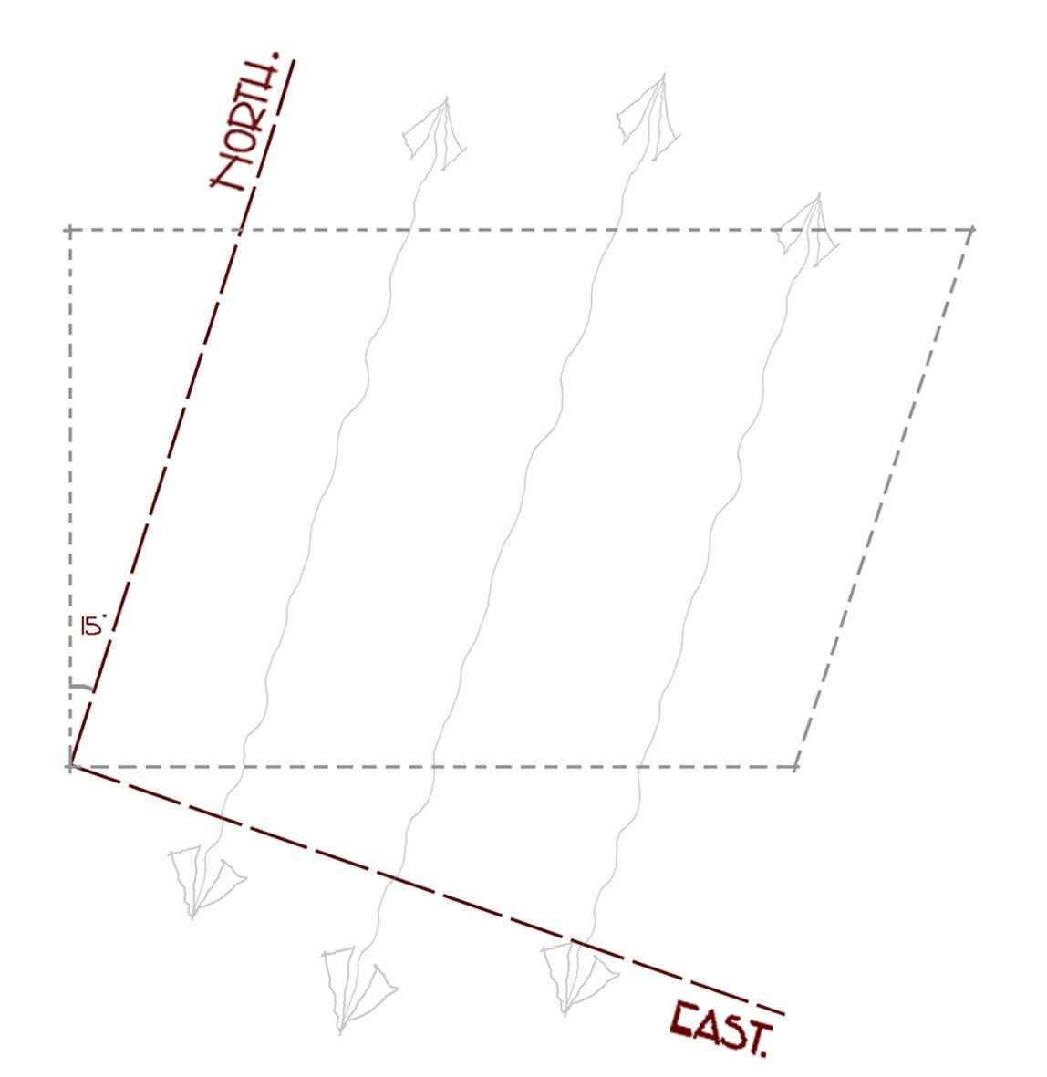
The studio focused on understanding sustainability and how it influences the way we build for the given context. After thorough studies, our aim was to be led by the principles of performative architecture and passive design strategies to help with sustainability. The studio also focused on understanding certain parameters to aid the design process. The main parameters that were addressed include form, orientation, shading and thermal comfort.
MENTORS
Kukke Subramanya
Nelson Pais
Anjali cheriyath
Vidyashankar
Suren Aalone
Dyan Belliappa
SITE LOCATION
MUDA Layout, Mysuru
SITE AREA 3000 sqm.
DURATION
10 weeks
27 03.
The site is located in MUDA Layout in Mysuru, which is a residential layout in Mysuru. The scale of the buildings surrounding the site and, are the most, double storeyed houses.
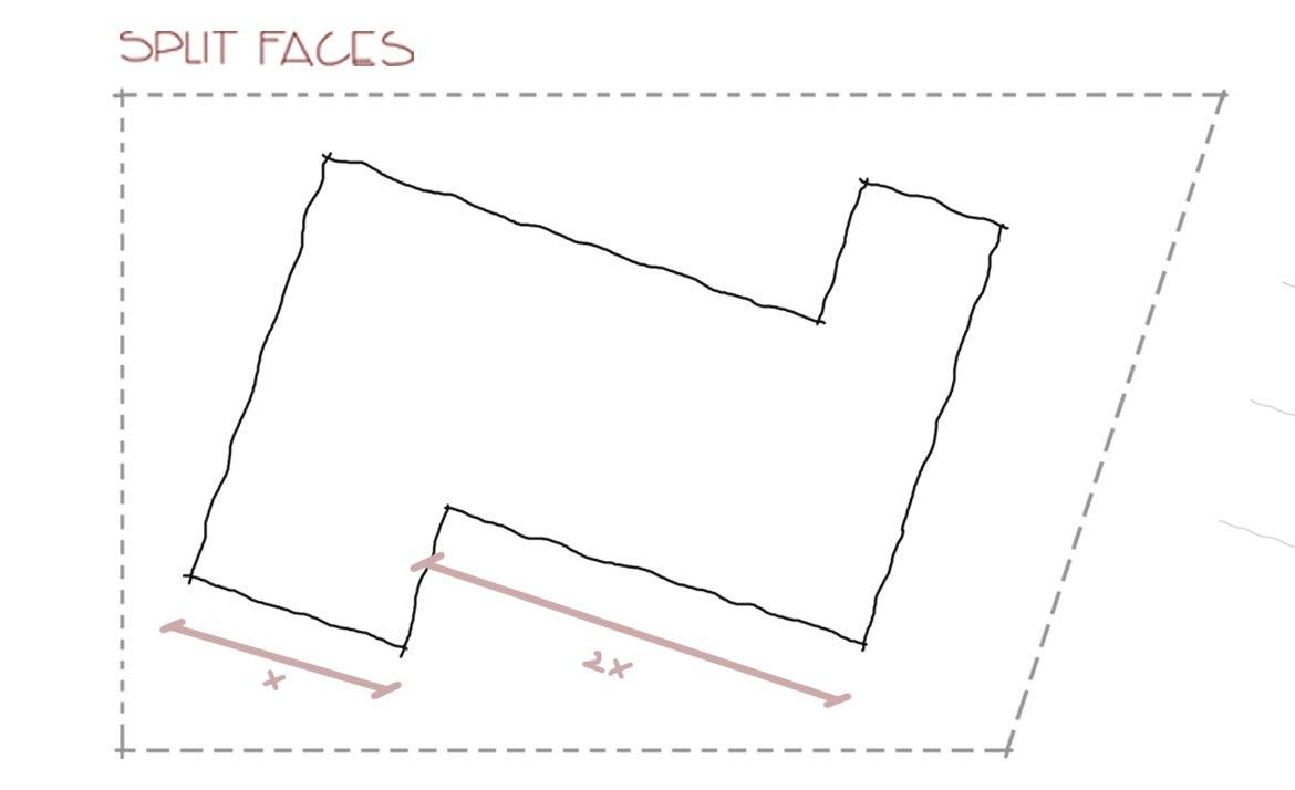
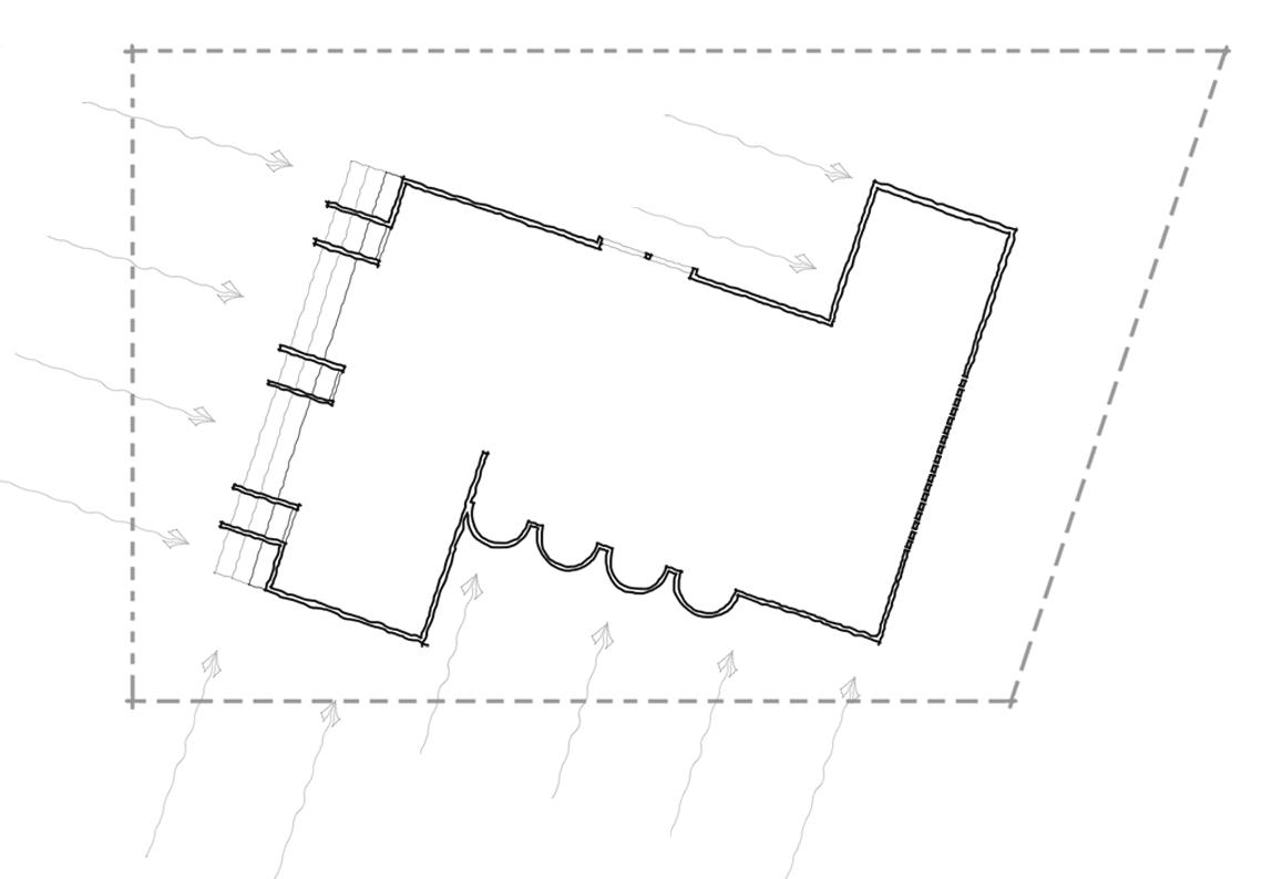
The design was initially approached diagrammatically in order to explore certain strategies (form, orientation, passive cooling, shading, thermal comfort). These explorations formed the basis for the design process.
MUDA Layout
12.2877° N, 76.6109° E
28 Portfolio.
N
29
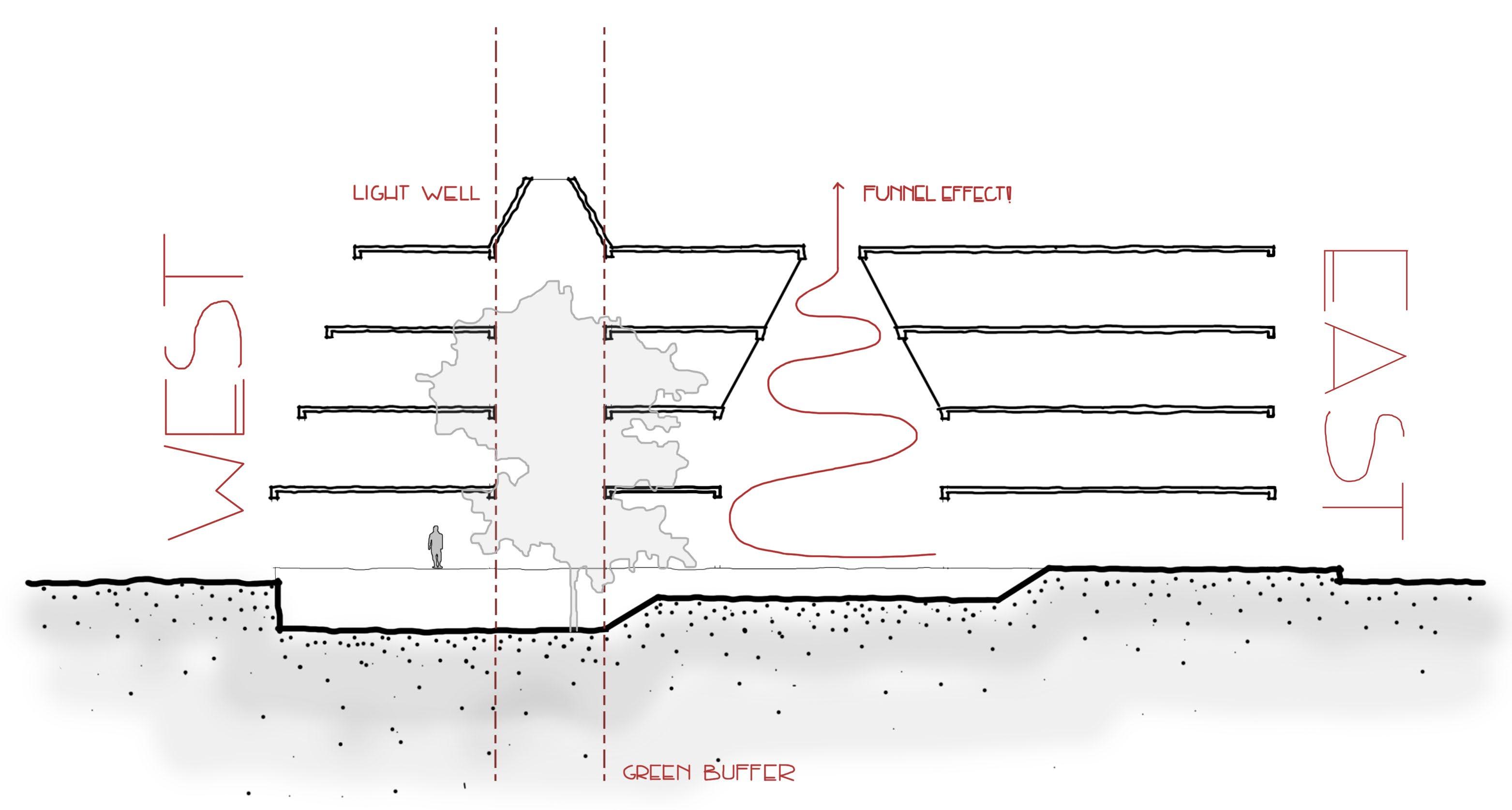
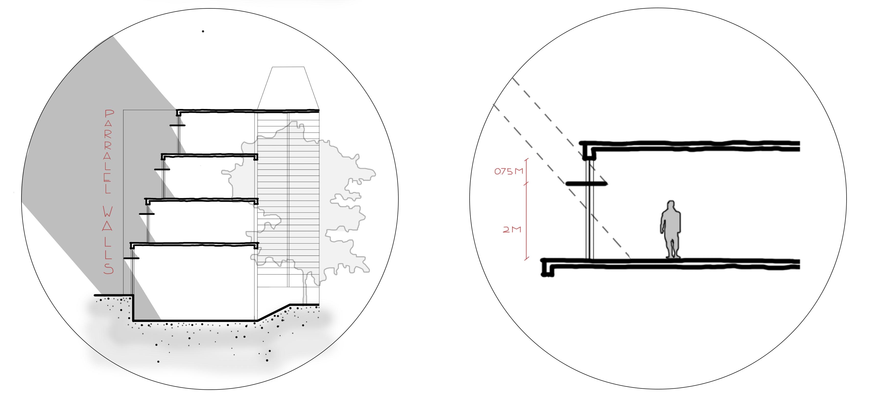
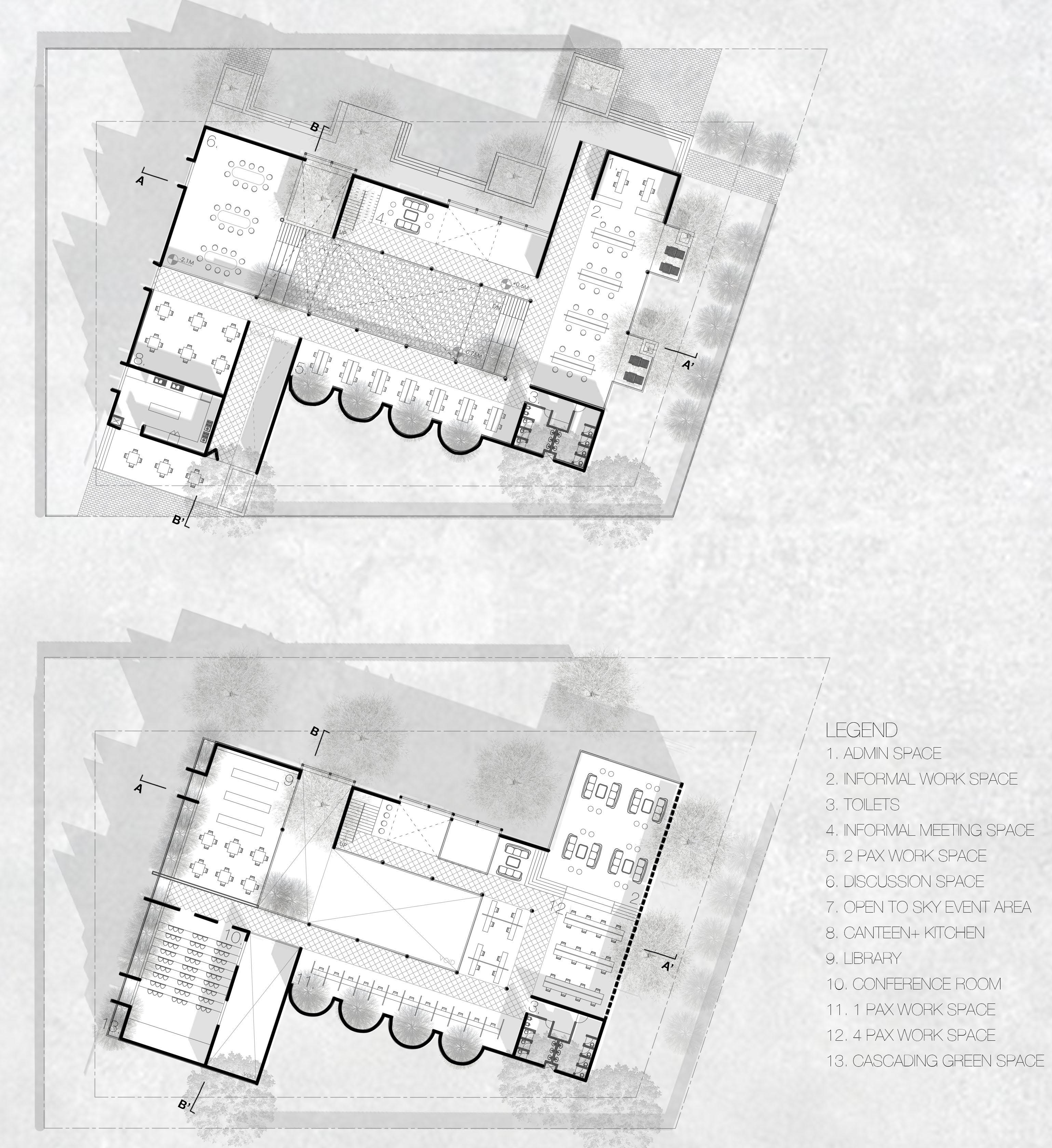
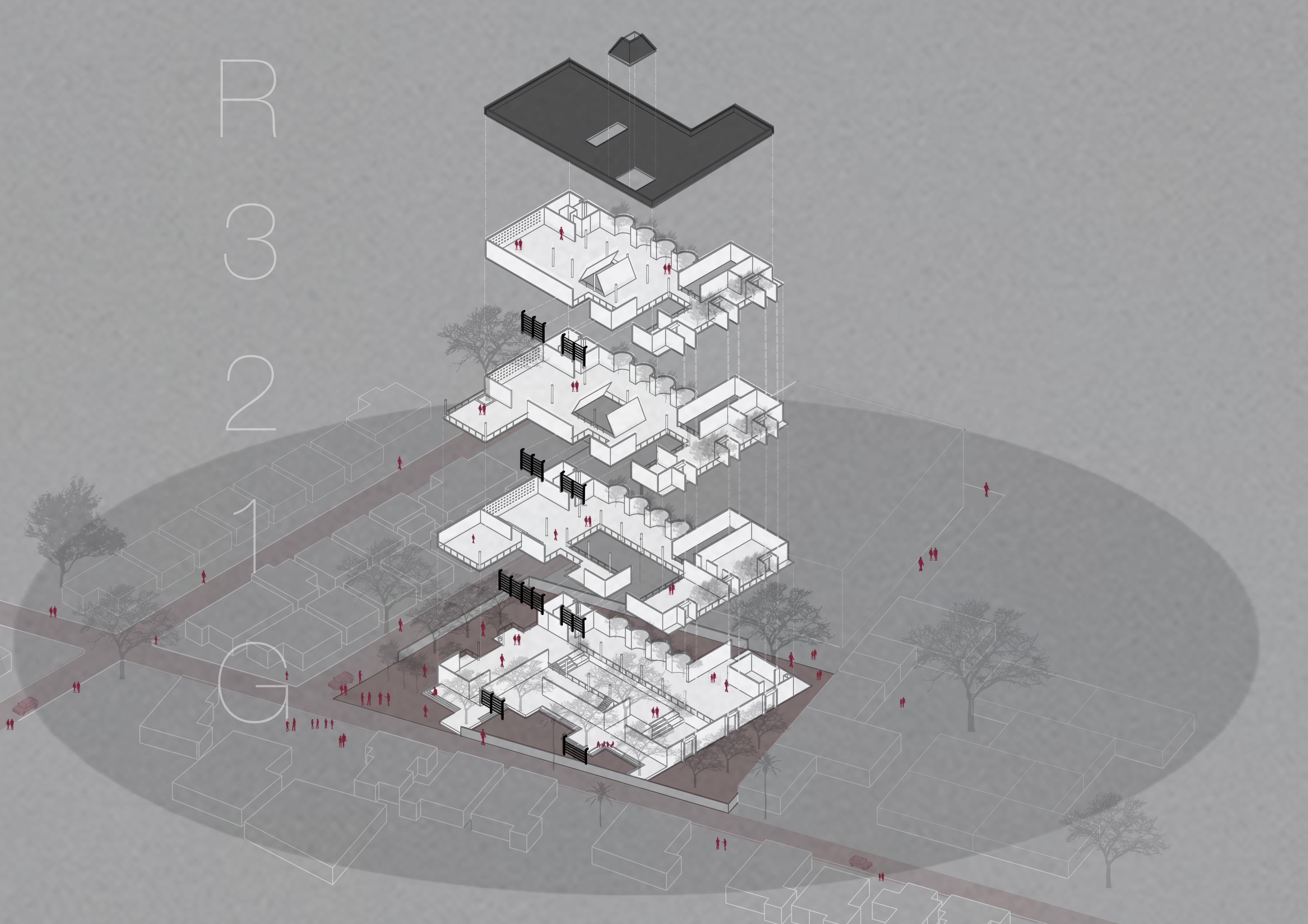
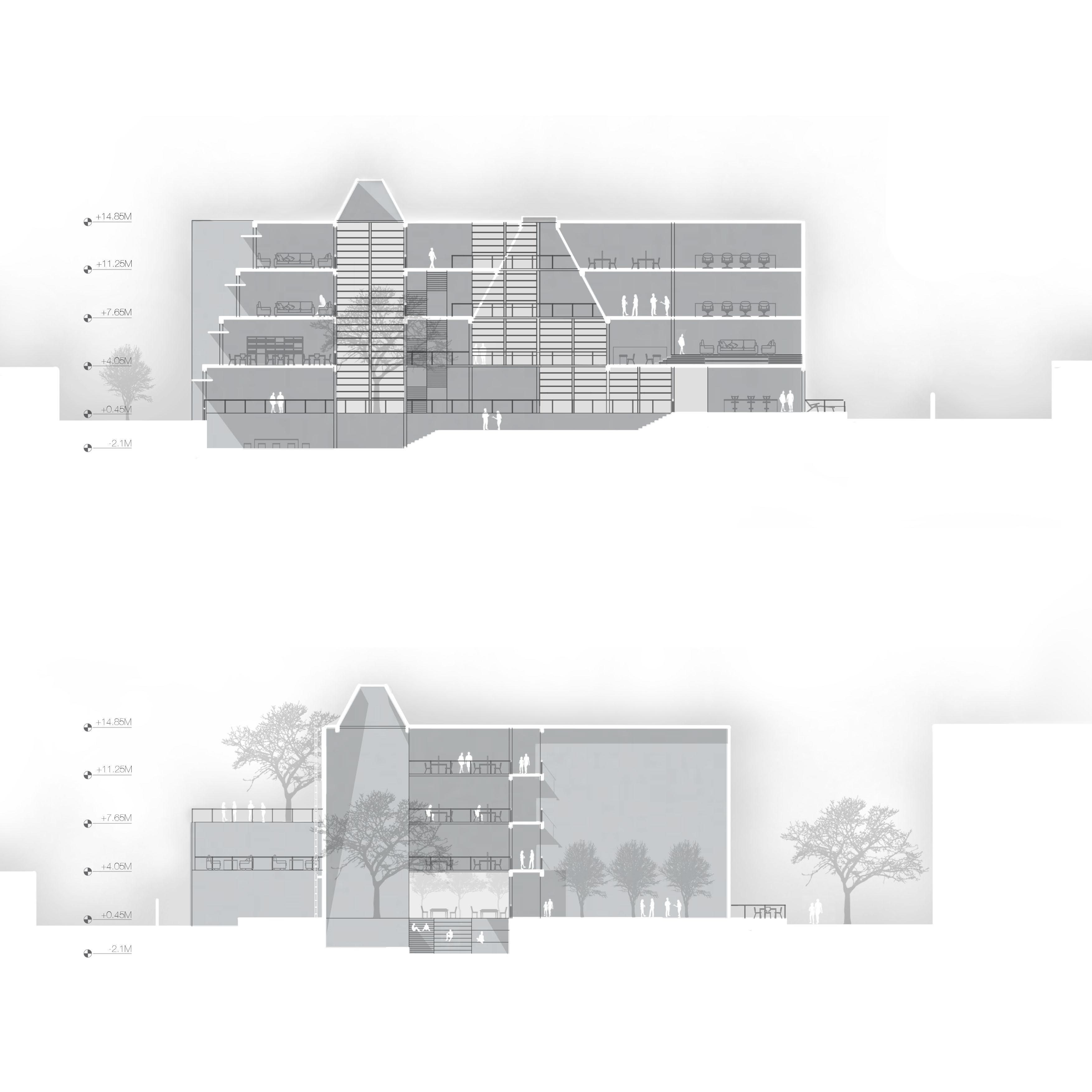
Floor Plates Window Detail +0.45M GROUND FLOOR +4.05M FIRST FLOOR +7.65M SECOND FLOOR +11.25M THIRD FLOOR -2.1M +14.85M ADOBE MUD BRICK PARALLEL WALLS WOODEN LIGHT SHELVES TERRAZZO TILES CONCRETE SLAB 25 MM FIXED GLASS 2300 600 750 ADOBE MUD BRICK LIGHT WELL WOODEN LOUVERS Western Facade: Wall Detail
Sectional
Idea: Funnel Effect Cascading
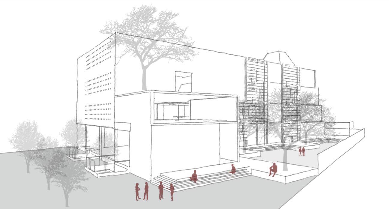
View from road
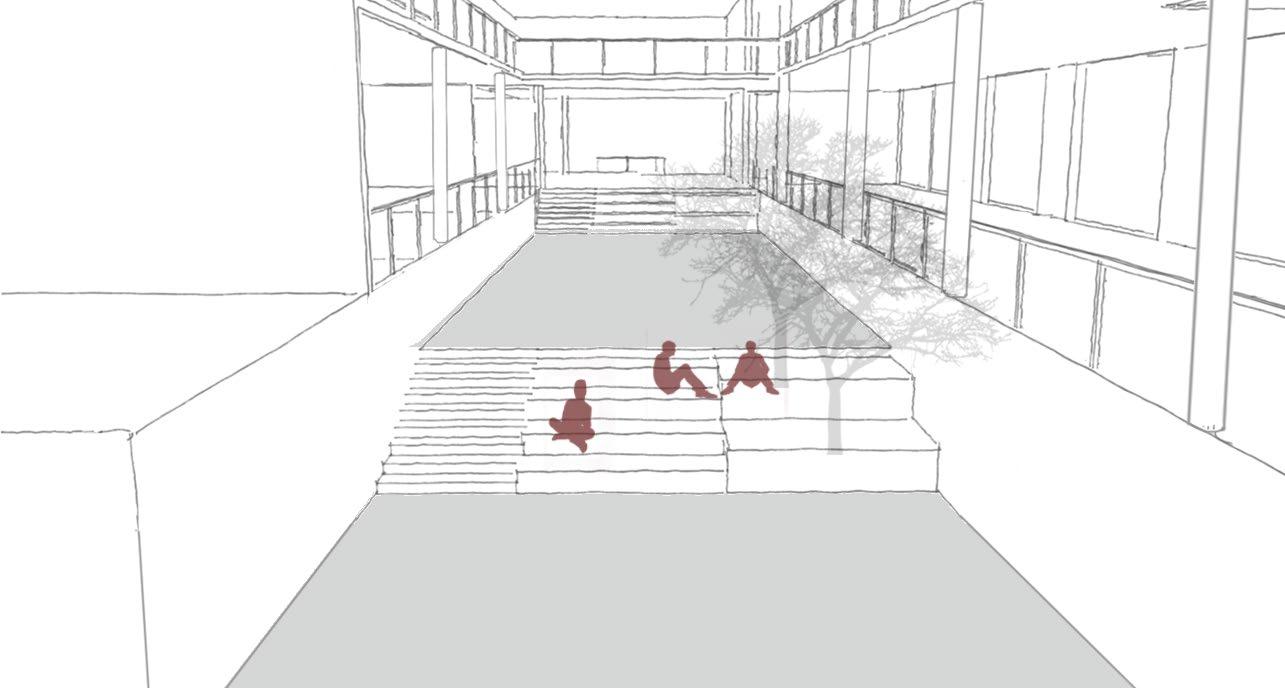
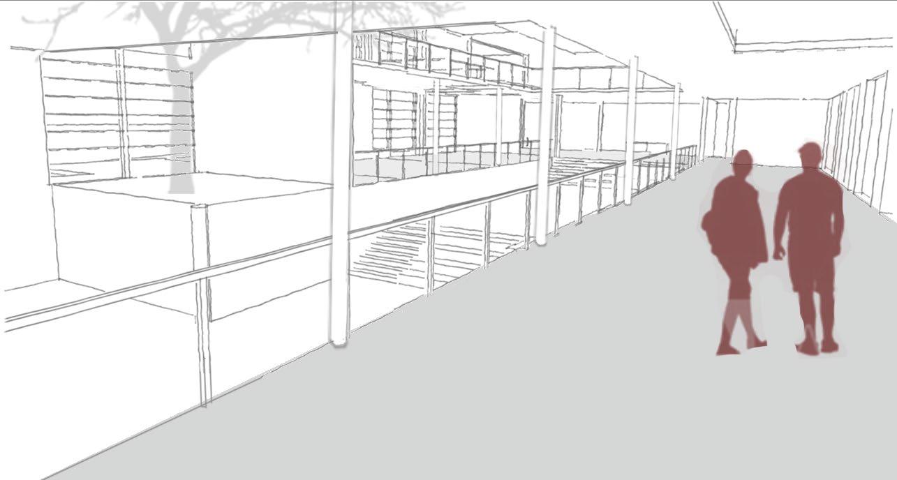
On ground floor- beside event space
On lower ground floor- event space

30 Portfolio. 0 1 2
Plan at +1.5M
Plan at +4M
Exploded Isometric View

Meeting rooms
Toilet
1 pax work space
2 pax work space
4 pax work space
Discussion rooms
Meeting rooms
Toilet
1 pax work space
2 pax work space
4 pax work space
Discussion rooms
Informal work spaces
1 pax work space
4 pax work space
Library Conference room
Informal work space
Toilet Admin space
Informal discussion space
Open to sky event
0 1 2
Along with the importance given to the passive design strategies, the main intent was to create a building that satisfies the requirements of what a co- working space should be along with creating a conducive work experience.
The co- working space so created allows for people to be connected to one other through the porous volume of the space so created and at the same time also creates personal pockets of spaces to work with no interruption.
The connect that the building has to the surroundings and to nature is strong, owing to the porosity that the volume and the skin offer.
There is also a combination of formal and informal spaces that have so been formed in order to cater to the needs of a larger user group.
Section AA’ Section BB’
music institute.
STUDIO BRIEF AND INTENT
The semester intended to introduce students to the various aspects of designing a music institution by understanding an institution’s intent, philosophy and programmatic requirements, and to translate these into a functional building. The design was meant to constitute relationships between courses, batches, between faculties and students and between public and the campus. The semester also aimed at delving into the process of understanding and design of a high rise building.
MENTORS
Anand Krishnamurthy
Asijit Khan
SITE LOCATION
VV Mohalla, Mysuru
SITE AREA
3864 sqm.

DURATION
14 weeks
33 04.
The site is located in VV Mohalla in Mysuru, which is one of the busiest commercial areas in Mysuru. The buildings surrounding the site have a large built up area, owing to the presence of commercial buiildings and shops.
The design was initially approached diagrammatically in order to understand and explore the form, orientation and experiential quality of the space.

Single volume
Splitting of volume in order to separate accomodation space and institutional space


Further deductions keeping in mind area requirements of spaces+ connect between two volumes and formation of courts
Skin development+ Bringing element of publicness into space through public plaza Music connects people- it binds them. Thus, a space to learn music should be no different. Through diagrammatic explorations, it was attempted to create a space that connected the students learning music through courts and volumentric deductions.
34 Portfolio.
N VV Mohalla 12.3251° N, 76.6312° E
Orientation of Buildings Surrounding the Site Breaking Monotony of Alignment
Plan at +1.5M


The publicness involved in music itself as an element could not be ignored. It was, thus, also attempted to create a differentiated public gathering space in the form of a plaza in order to bring the public into the space, in the event of a music performance or a gathering, and to create a space that could also be used during the times the institution does not function.
The fact that VV Mohalla is a bustling commercial space with a high footfall makes it essential for the design proposal to respond to it. The boundary wall of the institution has been made porous at certain parts to make it easier to differntiate between spaces that can be accessed by the public and spaces that are specifically owned by the institution.
35
0 2 4
The spaces on the upper levels follow the same character as the ground floor; it was attempted to bring in porosity. Courts were formed on the upper levels as well in an attempt to create small niches for people to gather.
A connect between the two volumes was also made such that the spaces could be used in a convenient manner.


36 Portfolio. Plan at +6.5M
at +4.5M
Plan
0 2 4
Since the building is a high rise building, the sectional connect between the different floors becomes crucial. The building has been sectionally crafted to create a connect in between the spaces in the form of courts and volumetric deductions in order to enhance the binding character that music posesses.


37 0 2 4
Section AA’
An attempt was made to make the space more welcoming for the public from outside through courts and volumetric deductions.


0 2 4 Section BB’
sarkari hiriya prathamika shaale.
STUDIO BRIEF AND INTENT
The main intent of the studio was to design a public building. The Kannada movie ‘Sarkari Hiriya Prathamika Shale’ formed the basis for the studiothe town in which the movie was based in led to the public building being designed to be placed in that environment. The movie gave a wonderful narrative of a community in Kasargod- apart from the depictions of the nature of life in the town, a large part of the movie followed the lives of the children living in the town and their time in school. The public building itself was an extension of the existing school building. As a starting point, the footprint upon which the building were to be designed was given to be 12m*50m.
MENTORS
Kiran Kumar
Shreyas Baindur
SITE LOCATION
Kasargod
SITE AREA
7000 sqm

DURATION
16 weeks
39
05.
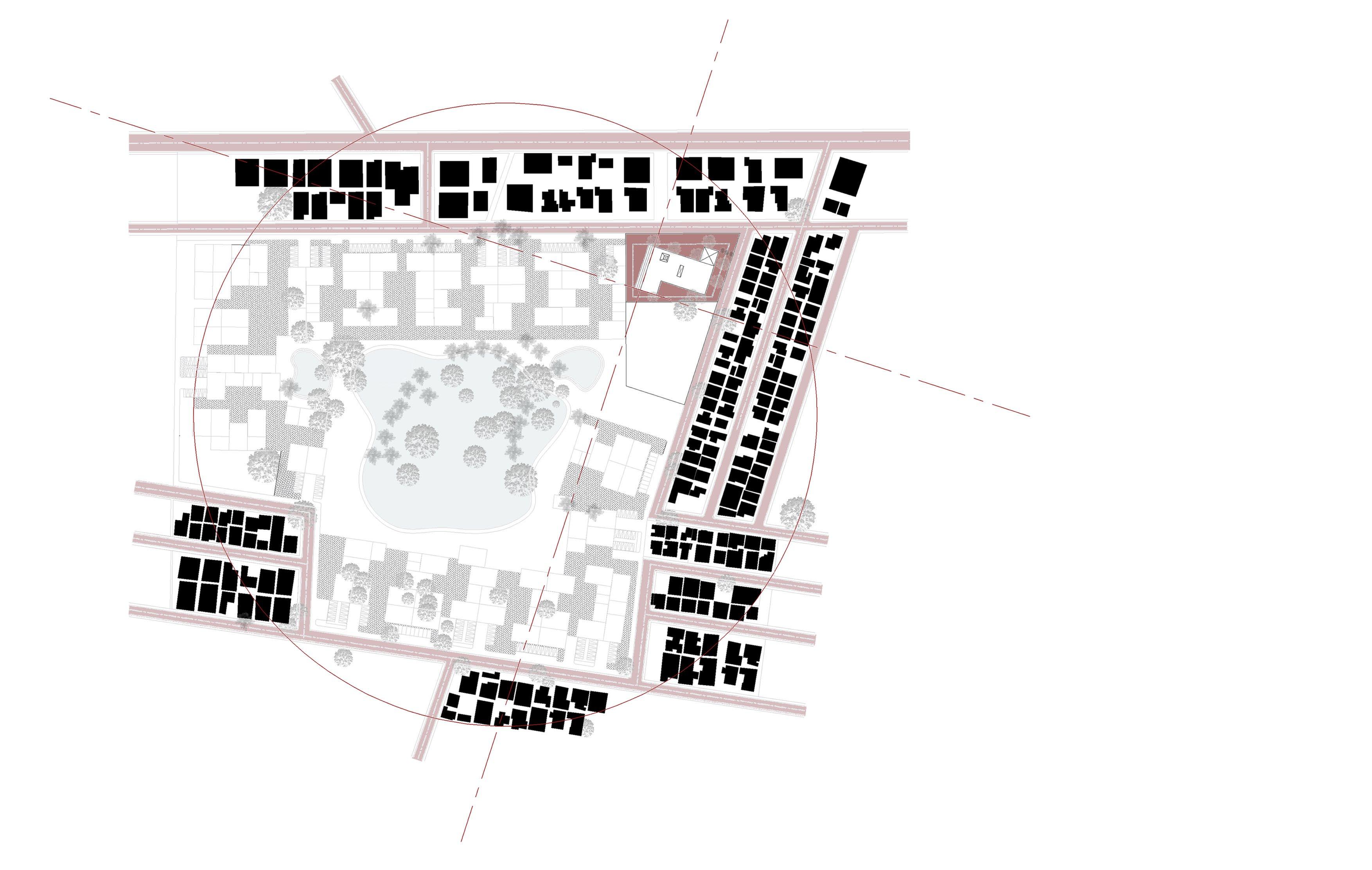
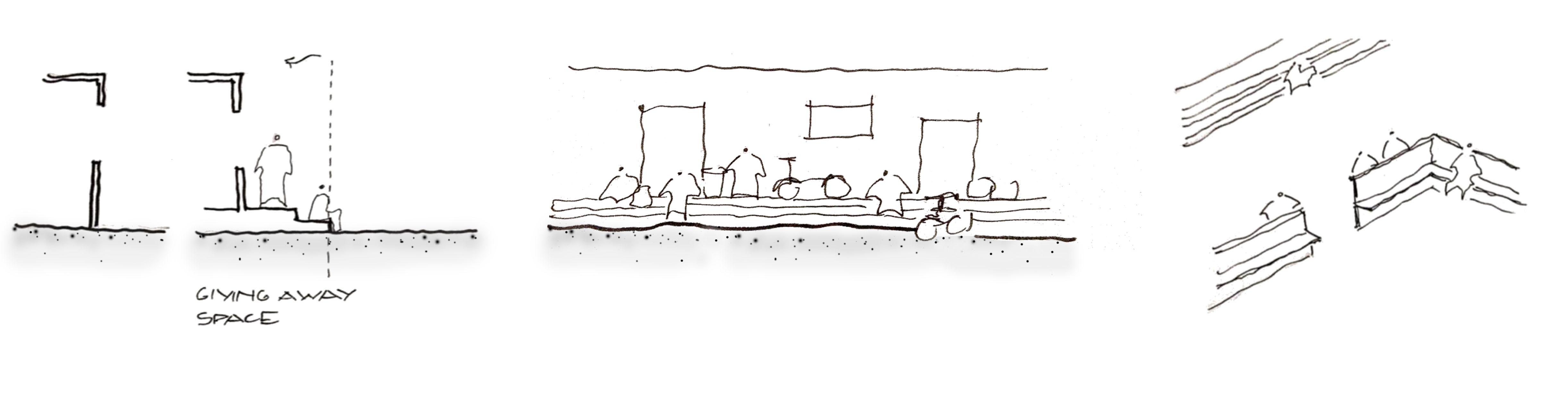
Giving away space in front of the building
Kasargod
12.4996° N, 74.9869° E
Connect between public space and road
STUDENTS OF SCHOOL
Because the public building designed is an extension of the existing school building, the students of the school become important stakeholders.
PUBLIC
The design aims to create a space for the residents of the town. In the movie, it was shown that the space in front of publicly used buildings became as important as the building itself. The space in front of the building became a threshold before entering into the building- a space where one can be a part of the space without completely entering into the building.

30
S T A K E H O L D E R S
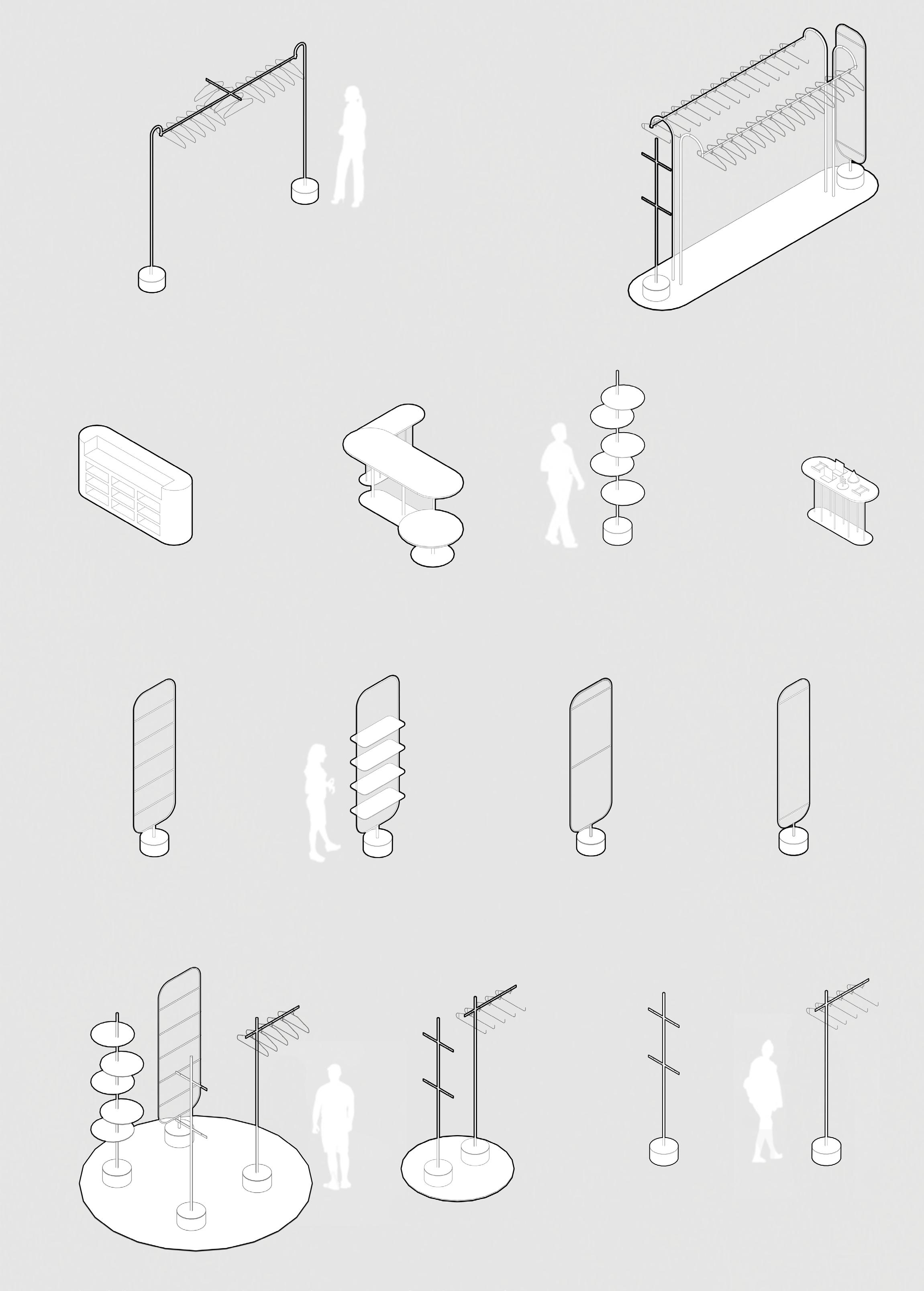
Usage of frontage of building
A number of programs were introduced, all of which were to be integrated into the public building. The first step at approaching these programs was to categorise them on the basis of how ‘public’ they were perceived to be. This categorisation further aided in the positioning of these programs in the building.
The movie ‘Sarkari Hiriya Prathamika Shaale’ became the basis for the semester. The nature of life and the context as shown in the movie became the basis to understand and approach the design.
The key questions that were grappled with this semester were-
1. What is the nature of a Public Building?
2. How does publicness find architectural expression?

3. Given the mixed use program, how does one organise this appropriately ? What frame do we use to bring them together in meaningful ways?
4. How do we critically respond to the particular conditions of a place (the town, its fabric, culture, character)? The main aspect that was looked into was the relationship in between a public space and a public building.
41
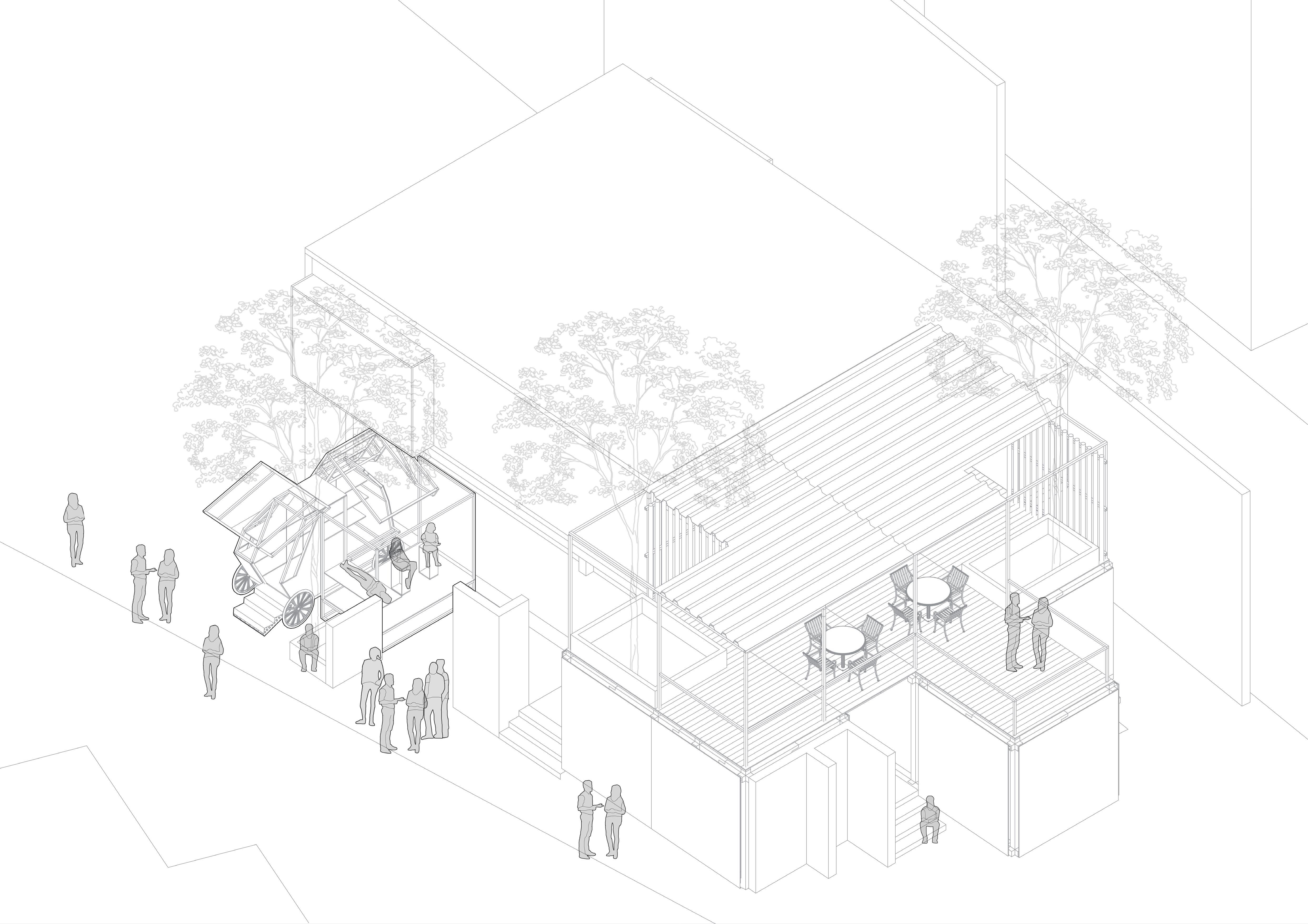
Sectional ideas on relation between building and space
Elevation becoming porous
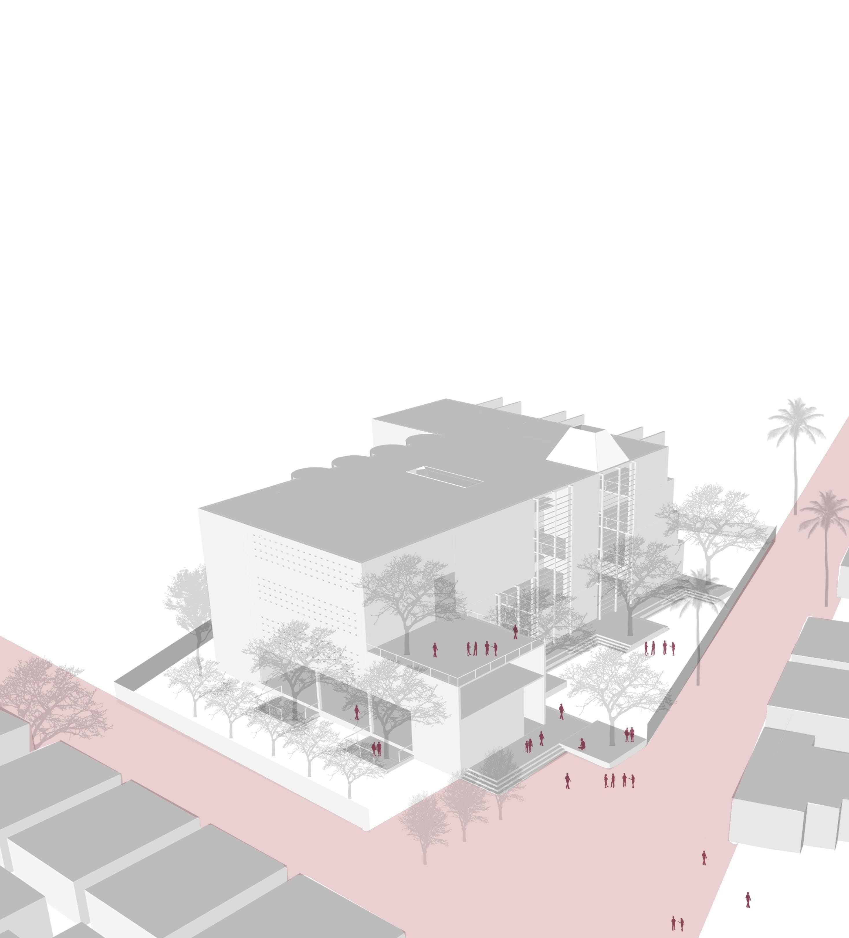
Position of footprint on site
Positioning of footprint-
Reasons for positioning and orientation of public building-
• All of the public building could be seen from the street
• To create scope for design of a public space. Public building becomes backdrop of the public space in front of it
The main idea carried forth from the movie was tbe presence of the public space and public building, and the relation between them. In the movie, it was shown that the space in front of publicly used buildings, such as shops, became as important as the building itself. The space in front of the building became a threshold before entering into the building- a space where one can be a part of the space without completely entering into the building.

42 Portfolio.


43 0 1 2
Section AA’
The moviement of a user from the road into the public space and then into the public building leads them to encounter a series of possibilities, options and pause points, similar to the character of life and spaces seen in the movie.
The entire proposal aimed to respect and respond to this character.
The key questions that were grappled with this semester were-
1. What is the nature of a Public Building?
2. How does publicness find architectural expression?
3. Given the mixed use program, how does one organise this appropriately ? What frame do we use to bring them together in meaningful ways?
4. How do we critically respond to the particular conditions of a place (the town, its fabric, culture, character)?

The main aspect that was looked into was the relationship in between a public space and a public building.

In the movie, it was shown that the space in front of publicly used buildings became as important as the building itself. The space in front of the building became a threshold before entering into the building- a space where one can be a part of the space without completely entering into the building.
The public space was created by plinth variations, and positioning of the open air theatre along the axis from the road to the building, while the public building was made porous through volumetric deductions and by making the skin porous.
44 Portfolio. 0 2 4 Plan at +0.5M

Wall Sections
Wall sections were worked on in order to detail the project to a larger extent. Three main materials were used in the proposal- adobe mud bricks (for walls), bamboo (for porous stilts) and concrete (for slabs and foundation).

46 Portfolio.
conceptual work.
models of ideas.
A House for an Artist and Author
The intent was to incorporate vernacular building methods into the design while choosing to use either low-tech or high- tech solutions.
A Cafe by Chamundi Hills
Since the site slopes down toward the lake, it was attempted to create a sense of movement towards it- sectionally as well as through the orientation of the form itself.
The cafe is designed to respond to the site in a manner such that the height difference of the various contour levels are taken into consideration .
The slab that cuts through the volume of one component extends out to form the roof of the next component.

06.
Email ID: bindumaringanti@gmail.com Phone: 9986576123
