Child Mobility View to the Lake
Design Challenge
Site

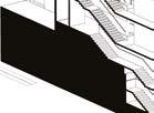
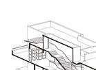
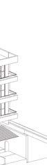
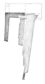
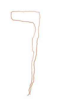
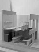
Considered ramp as a main design element for the physically disabled child to move throughout the site along with staircases that vertically connects the entire building.
Multiple platforms formed by the ramp act as different spaces based on their purpose. In this way each platforms has a different viewing experience to the lake. Hence, the view to the lake was never compromised as the spaces were separated by levels and not walls.
Design Features

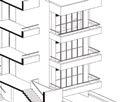
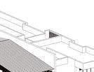
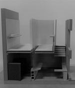
Feature wall separated the private spaces from the common spaces based on the activity of specific user groups.
The common space with double height volume traps up heat by the sun at the end of the day. Feature wall along with the stairwell, restricts the heat transfer from the common spaces to the private spaces.
The slowing down of heat transfer by the feature wall will give enough time for the cool breeze to extract heat from common space by cross ventilation process. Hence, the private spaces stays cool through out the night and provides a good air conditioning for the family spaces.
Be.m
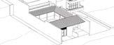
Feature Wall
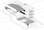
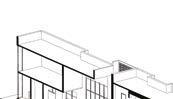
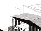
Final form
02


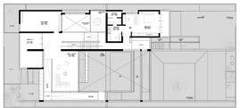
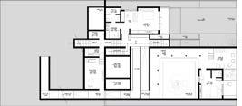
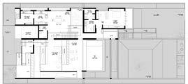
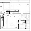
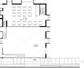
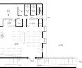
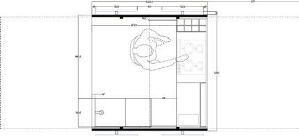
x x 3 1 7 6 4 5 29 31 30 32 35 33 28 26 25 34 23 24 36 37 2 2 1 3 4 5 10 6 8 7 9 12 14 15 10 11 21 20 18 x 13 16 17 8 9 22 19 Floor Plan @ +LVL 2.5 Floor Plan @ +LVL 4.5 Floor Plan @ -LVL 0.75 1. Family living 2. Family terrace 3. Dance studio 4. Bedroom A 5. Sit-out A. 6. Wardrobe A 7. Bathroom A 8. Common living 9. Pool deck 10. Dining room 11. Courtyard 12. Kitchen 13. Work Area 14. Guest toilet 15. Wash 16. Common Sit-out 17. Foyer 18. Bedroom B 19. Sit-out B 20. Wardrobe B 21. Bathroom B 22. Swimming pool 23. Main central courtyard 24. Office 25. Service 26. Gym 27. Water storage tank 28. Laundry 29. Electrical services 30. Wardrobe C 31. Bathroom C 32. Bedroom C 33. Sit-out C 34. Service 35. Office waiting lounge 36. Office toilet 37. Office sit-out 1. Asphalt road |Approach 1 , 2. Entry 1, 3. Family Terrace, 4. Courtyard 5. Terrace 6. Parking 7. Muddy Road | Approach 2 8. Entry 2 9. Ashtamudi Lake 10. Main Central Courtyard All Dimensions in m All Dimensions in m Floor Plans Site Layout 17 01 08 26 09 22 25 27 27 23 24 03
Floor Plans
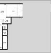
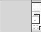
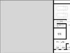


Be.m 0 F E D 1. Machine room 2. Water tank 3. Garage 4. Central courtyard 5. Visitor parking 6. Waiting lounge 7. Toilet 8. Office 9. Sit-out 10. Control room 11. Store room 12. Family living 13. Common living 14. Pool deck 15. Gym 16. Swimming pool 17. Family terrace 18. Car park 19. Powder room 20. Terrace 21. Sit-out A 22. Sit-out B 23. Sit-out C 24. Dance studio 25. Kitchen 26. Dining 27. Dining Courtyard 28. Bedroom A 29. Bedroom B 30. Bedroom C All Dimensions in m
Plan @ - LVL 2.1 Plan @ - LVL 3.5
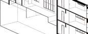
Cuts 04
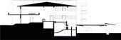
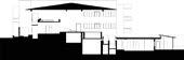
Section
Design Challenge
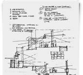
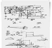
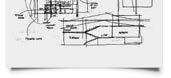
Design Development Sketches
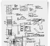

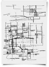
The disability of the youngest child to walk around the house has created a new design challenge. Since the site has a level differences in between, its even more difficult for a physically challenged child to access all the parts of the site. So during the design process neither the accessibility nor the view from the site was compromised. Hence, the idea of dividing the site into several small levels was an optimal option where, each
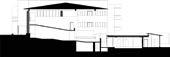
levels are considered as different spaces. These spaces has no walls and are connected with the help of ramps such that the child could access all the spaces in the site. However, with the minimal usage of walls, the spaces gives a maximum view to the lake with less visual obstruction.
Be.m
05
CET Amenities Center
Undergraduate Project

5th Semester Individual Undergraduate Project 3rd Year Design Studio
Software used:
About
Project
College of Engineering, Trivandrum campus, Kerala, India
2016 964 sqm
To propose a design of canteen with amenities center for students, staffs and visitors in order to improve the social interaction of the specific region in the campus.
Faculty Design Guide : Project Involvement :
Location Hospitality Dr. Sunil Edward From concept development to final design presentation
Type Year Area Brief
02
06
Be.m
Site Accessibility and Connectivity
The site can be accessed by 3 different approaches in the campus layout.
R1
R2
R3
Connects the site with main administrative building. Quickest and the easiest route for the service vehicle from entrance 2.
Access for large number of event visitors to the site from the amphitheatre and physical education playground
Close proximity zones to site
Site
1. Site 2. Reprographic Center and Stationery 3. Main College Entrance 4. Central Administration Building 5. Department of Architecture and Planning 6. Department of Business Management 7. Department of Computer Science and Engineering 8. Amphitheatre 9. Multi-purpose Hall 10. Physical Education Playground 11. Department of Civil Engineering 12. Department of Applied Electronics 13. Industrial Workshops 14. Diamond Jubilee Auditorium 15. Entrance 2 16. Main road from the town
Be.m Campus Regional Layout
User group movement pattern and frequency of visit to site Students Teaching Faculties + Staffs Campus Visitors Type 1 Campus Visitors Type 2 Frequency of Visit Frequency of Visit Frequency of Visit Frequency of Visit
Frequent circulation all throughout a day Time specific circulation to limited areas in the campus Circulation limited to mostly in and around the administration building Circulation around the event area for a day High Medium Low High
07
User Group Activity Analysis
The movement of staff and students to Zone 1 from Zone 2,3 and 4 to access the transportation road, is mostly through Exit 1 when compared with Exit 2. This movement pattern is mainly due to the frequent activities of staff and students related to zone 1 and the quickest approach to it.
Zone 1 : Reprographic Center, Stationery shops, ATMs, Restaurants and Bus-station (Public transport to main city )
Zone 2 : Amphitheatre and Multi-purpose Hall
Zone 3 and 4 : Engineering Departments and Industrial Workshops
Design
Primary Idea: Create a shortest route through the site to access road R1 that leads to the main transportation road.
Secondary Idea: Distribute and redirect the flow of crowd through the site to maintain a balanced circulation in the specific region of the campus. In this way the passage encourages more visitors to the canteen and makes the entire space lively in the region.
R1 - Access road 1
R2- Access road 2
R3- Access road 3
Circulation path
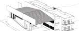
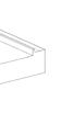
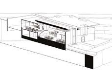
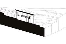
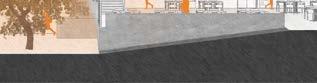
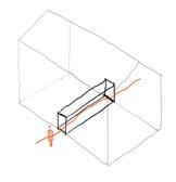
Form Development
The huge volume of space considered as cuboid
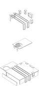
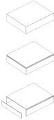
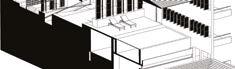
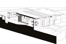
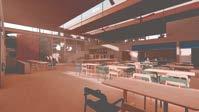
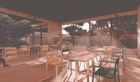
The gap between roof and the wall reduces the enclosed space feel in the interior spaces and increases the connectivity to the exterior.
The main connecting passage crosses through the huge volume of the built form with one of its wall acting as a directing element
Natural light source to interior spaces
The circular hole at roof, highlights the trees in courtyard with sunlight. The light makes tree a decorative element of the space.
Final form
Be.m Exit 2 Exit 1 R1 Zone 2 Zone 3 Zone 4 R2 Site Zone 1
Built form Connecting Passage R1 R1 R2 R2 R3 R3 Site Site 08


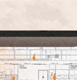
Be.m 09 Section Cuts A B C D Courtyard Department of Architecture and Planning Department of Computer Science Amphitheatre Department of Civil Engineering Pond Parking Common and Staff Dine 3.8m Wide connecting passage Faculty Parking Landscape 7.5mwideroad 4.7 m wide road Entry 3 Entry 1 Entry 2 Service Entry Landscape Student Dine Bridge 1. Main Passage 2. Common dine 3. Courtyard 4. Bridge 5. Pond 6. Water-Storage and Filtration Tank 7. Fire Fighting Water Tank 8. Parking A 9. Student Dine and Cafeteria 10. Rest-room for women 11. Rest-room for men 12. Kitchen and Service 13. Staff Dining 14. Service to staff dine from kitchen All Dimensions in m Site Layout Common Dine Student Dine 2 9
The rain water runoff from the site slope, is collected in a pond tank and is precipitated to the ground after rainwater harvesting
The skylight in the roof illuminates the courtyards and the interior spaces.
The opening in the wall allows better cross-ventilation through the interior spaces.

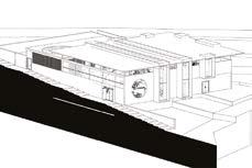
The form has been made monumental in scale in order to be visualized as a landmark in that area.

All Dimensions in m Floor Plans
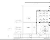
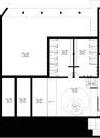
1. Entry A 2. Common Dine 3. Courtyard 4. Women’s Rest-room 5. Men’s Rest-room 6. Pond 7. Water Tank 8. Water Tank for Fire Fighting 9. ATM 10. Reprographic Centre 11. Office 12. Food Serving Counter 13. Kitchen 14. Storage 15. Staff Toilet (Women) 16. Staff
Toilet (men) 17. Service Stairs for Staff Dine
18. Service entry 19. Parking 2 20. Bridge 21. Student Dine 22. Entry B 23. Staff Dine 24. Serving Counter 25. Entry C. 26. Faculty Parking
Be.m
A B C D
Plan - @ LVL 1.5 Plan - @ LVL 1.5
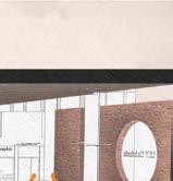
All dimensions in m Sectional Perspective 10

11
2 x 2 Kiosk About
Undergraduate Project
4th Semester Individual Project | 2nd Year Design Studio
Software used:
Type
Location
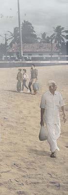
Shangumugham beach, Trivandrum, Kerala, India
2014 4 sqm
Faculty Design Guide : Project Involvement :
Hospitality Prof. Jinoj M From concept development to final design presentation
To design a kiosk unit as a reinterpretation of the native movable kiosk. This is considered to be a general design for all the units that are proposed to be located in the Shangumugham beach.

Project
Year Area Brief
12 03
Be.m
Kiosk
Design
The form was inspired from the gabled roofs of Kerala’s traditional architecture
Keeping the roof profile in focus, a simple geometric shape of a triangle was considered. A prism shape was derived to add a three dimensional volume to it.
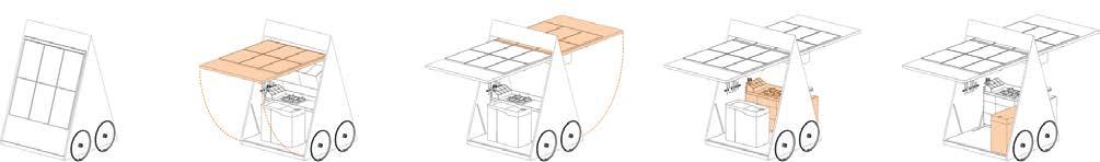
To access the interior, 2 faces of the prism act as major open-able shutters , at the same time the it serves as a shade for the structure.

Be.m
when it is not active with its shutters closed The back shutter is opened first, with the movable counters arranged inside.
Then front shutter is opened with help of a hook, which is only accessed from inside.
The cooking counter is pushed to the front till along its tray rail.
The wash sink is pushed to the right side creating sufficient space for the vendor to perform his action.
Roof Profile
13
Sectional Perspective
All

Be.m
Solar panels installed on the topside of the shutter for the power required by the kiosk
Hinge mechanism for swing shutter door
Suspended aluminium cabinet storage.
Cooking top on the counter with easily cleanable surface material
Drawer cabinets for extra storage
An enclosed space for the LPG gas cylinder.
Tray rail for the counter to be push slided forward upon opening of kiosk
Battery located at the bottom of the kiosk. It is powered by the solar power panels installed at the exterior face of the shutter panel.
Dimensions in m
Diamond plate metal flooring screwed to the base frame to provide sufficient slip resistance.
An inclined groove in the base for the shutter to be flushed with surface when closed.
Hydraulic piston [4] supports the shutter panel
LED light
WPC panel screwed to metal framed shutter panel
14


Be.m
All Dimensions in m
1. Suspended Storage 2. Central Light and Hinge Mechanism 3. Counter Storage Compartments 4. Cutlery Rack 5. Wash Sink 6. LED Light 7. Cooking Counter 8. Segmented Storage 9. Solar Panel 10. Bicycle Wheels
Section ( Closed Shutters )
Front Elevation 15
Section ( Open Shutters ) Plan
@ +LVL 1.5
The T - eat
Post-graduate Project [1st semester]
Individual Project MA Interior Architecture and Design
About
Project Type
Location
Cafe +Allotment
Cobden Chambers, Pelham St, Nottingham NG1 2ED

Year
Brief
2021
To introduce a green culture of the allotments in the UK to the urban fabric such that people get involved in healthy practice of cultivating their own food and other food ingrediants along with having a leisure spot for them rather travelling a long distance to access the town garden.
Faculty Design Guide
Project Involvement :
Joe Laybourn
From concept development to final design presentation
Software used:
Be.m 04
16
In the 1800s Cobden Chambers was used as a photography studio for Nottingham’s society of artists. In 1890 it was the registered office for Notts County Football Club. From the 1970s it was used as the editing house for platform a monthly arts magazine for the midlands. From the 1980s it was home to a Horologist.
Cobden Chambers Pelham St, Nottingham NG1 2ED Was Now

Cobden Chambers is home to a number of exciting, creative businesses making and selling everything from quirky home accessories, to vintage and antique items, to boutique fashion, jewellery and music.
Based at the top of Pelham Street and comprised around a large central sun trap of a courtyard, Cobden Chambers is made up of Cobden Terraces and Cobden Place. The Courtyard plays host to pop-up street food vendors, markets and street art, drawing visitors into the Chambers and creating a dynamic, vibrant atmosphere.
Be.m
N N
Scale 1:10000 Scale 1:500
17
Noise Study Analysis
Understanding of the noise levels on each area of the site was important for appropriate zoning of each spaces according to the design brief. A study was done based on the noise level considering the user movement frequency and activity

Light Study Analysis
Intensities of the natural light were analysed in different areas of the site at different times of the day to find a suitable spot for various spaces based on the project requirement
Tunnel Courtyard 1 Courtyard 2
Be.m
A B C A B C 01 02
18
A B C
Strategy 01 02 1 2
Sequence of Spatial Experience

<<Entry Exit>> Harvesting Touch Smell Taste Processing + Storing Serving


2 1 2 19
Be.m
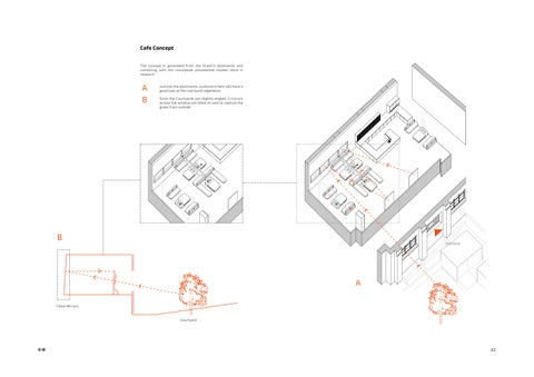
In order to capture the allotment green to passer-by on the street, a huge mirror was placed at the line of sight of a person at the tunnel transition space. Such that the tunnel exit frame captures the green first to the user acting a pulling factor to the courtyard Mirror Captures Green Allotments Courtyard 1 Pelham St.
Design Features
Spice Production
Be.m
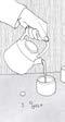
Ramp Ramp Glass House Sustainable Drainage Solution Increased Volume Universal Passage B A D C Courtyar Isometric View Strip Drain Glass House Glass House Slot Ramp 20 Sustainable Design Solution The heat generated from the machines used in the processing of the spices will we transferred through underground to the glass house next to the workshop such that it adds to the overall temperature of the glass house in addition the natural source
01 01 02 02 11 10 03 03 04 04 05 05 06 07 07 08 Drying Roasting Grinding 08 09 09 07 06 04 11 10 10 11 Product Display + Cafe Extended Customer WC Entrance Staircase Platform Lift High Seating Community Workshop Storage Spice Wall Spice Processing Machines Workshop Toilet
Spice Wall + Working Counter
Spice Experience Table
Each compartment of the wall stores each different spices
A B C D E F
Ginger Clove Cinnamon Cardamom Black Pepper Green Pepper
Product Display
Connecting Element
Workshop Storage
As soon as

Be.m
A B C D E F Ground Floor Basement
The same product which is packed in jar and stored in the spice wall itself a display unit for the customer in the ground floor
the spices are process it is packed in jar and stored on the spice wall
This Spice wall act as a connecting element between both the floor but the function of the wall changes with levels
21
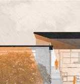
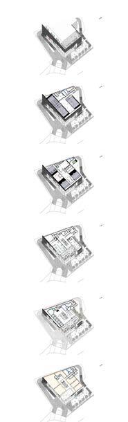
Conceptual Collage

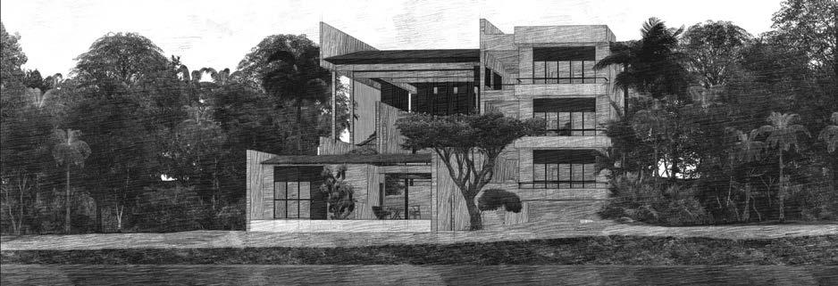
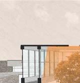
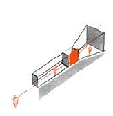
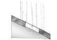
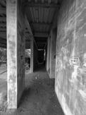
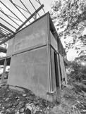
Depending on the slope the building has a dominant side for the view to a wider range of landscape/context. In this Volume 1 is higher than volume 2.


This results in much wider opening on the existing structure to capture the dynamic landscape.
The site is entirely surrounded by dynamic canvases with sky and landscape
Be.m
A B
C 27 A B
C
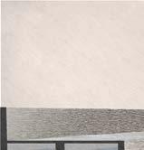
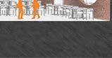
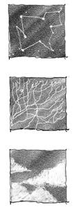
Static Pattern Source

Natural Dynamic Pattern Source

Layers
The sun being the main source for the shadows is the main dynamic element in nature
The branches of the trees (Natural Dynamic Pattern Source )which acts as a source for the shadow pattern is also dynamic in nature as it grows every day and can possibly change its position based on the weathering pattern by nature and seasons.
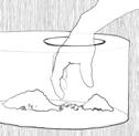
When introduced to a medium of water the refraction caused more variance on the pattern.
These layer systems provide an infinite number of pattern formation with the help of nature

Be.m
Stars Leaves + Branches Clouds
A B B C 28
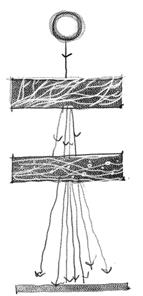
Capturing the Light
In order the form the dynamic shadow pattern the chimney being the tallest existing structure was used a receptor of light
The light received will then undergo multiple reflection with the help of mirrors placed inside to make light travel to the lover part of the chimney shaft

The light then goes through a water chamber which will thus help in the additional dynamic layer for the formation of the pattern on to the feature wall outside the building.
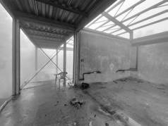
Traces of the Old Roof
Sense of Place
The metal can be integrated in such a way the sound from the nature such as rain falling on top of a metal will generate sound and will help the user to identify the old broken left over roof position with the help of sound
Be.m
1 2 2 3 3 4 4 5 5 1
Corton steel is shaped in the form of the old existed roof of the building to mimic the past
29
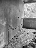
The detail show how the new wall made with the combination of brick and precast concrete is connected to the existing limestone masonry wall.
122.5 mm x 122.5 mm I Profile Steel Beam
189 mm x 103 mm L Profile screwed to I Profile Beam
4x 10mm dia bolt screwed to the I Beam
440 mm thk Limestone Masonry Wall
87 mm x 50 mm C Profile screwed to 10 mm metal plate
15mm Cement Mortar
2x 10mm dia bolt screwed to the C Profile Steel 10 mm plaster finish
Be.m Scale 1:30 Scale 1:20 Scale 1:20 Isometric view Detail A Detail B A B A B 01 02 03 05 06 07 08 04 Resolved Connection Detail 01 02 03 04 05 06 07 08
30
Annotated Detailed Section
Associated callout detail between the existing wall and the new wall of the intervention
Section Detail A
Be.m 20 mm Plaster 5 mm Corton Steel 15 mm Metal 6 mm Vapour Barrier 60 mm Thermal Insulation 122.5 mm Reinforced Precast Concrete 122.5 mm x 122.5 mm I Profile Steel Beam 189 mm x 103 mm L Profile screwed to I Profile Beam 87 mm x 50 mm C Profile screwed to 10 mm metal plate 103mm thk brick wall with 10mm binding mortar 15mm plaster 10mm plaster 200mm thk Reinforced PCC Floor Slab 30mm thk Floor Cement Screed 10mm thk Cement Micro Topping 440 mm thk Limestone Masonry Wall 40 mm thk Timber Panel Landing for stairs 01 01 02 03 03 04 04 05 05 06 06 07 07 08 09 09 10 10 10 A A 11 12 14 15 16 17 13 11 11 12 12 13 14 16 15 17 06 07 08 09 04 05 03 02 Scale 1:20 Scale 1:5
31


Be.m Proposed A’ A’ Proposed Bedroom Bar Toilet Extended Living Living Room Extended Dining Dining Fitness Room Kitchen Parking Utility Kayak Gear Store Water Body Lift 2 Lift 1 Ramp to fields Foyer Library Publishing Inspiration space Wardrobe Master Toilet Master Bedroom Entry 2 Ground Floor Plan First Floor Plan Proposed Section AA’ 1 9 1 2 10 11 12 13 14 15 16 17 18 19 20 22 23 24 2 3 3 4 5 6 7 8 7 8 9 9 17 8 18 19 20 10 10 11 12 13 14 15 16 4 5 6 Entry 1 21 22 23 24 A A 17 3 16 32
Vythiri Farmhouse
Professional Practice Team project [ 5 members ]
About
Project Type Year
Location Holiday villa
Vythiri, Wayanad,Kerala, India
2017
Brief
The project objective is to design the interior of the farmhouse located at the top of misty hills in wayanad’s Attapadi reserve forest. It serves the purpose of a holiday villa in the aysha plantation; one of client’s real estate properties on the hills. The site is located at an altitude of 1200m above sea level, giving a breathtaking view overlooking the valley.

Design Team:
Ar.George Seemon, Ar.Rohit Garabadu, Ar. Bibin Mathew Sakshi agarwal, Janhavi shinde
Project Involvement :
Material selection, Furniture and floor layout, 3D- Modeling, ,Presentation, Site co-ordination
Be.m 06
33


Be.m X Y Y Notes. Special Notes. Partner Architects. Project Title Project Code Sheet Title Project Architect. Drawing status.Drawing No. 186,18th Main, Cross,6th Block,koramangala, Bangalore-560095, India. 91 25503796, 41288506 architecture planning interiors 1:75@A2 Ar.George Seemon Drawn. Ar. Rohit FARMHOUSE AT WAYANAD Mr. Ashique Thahir AR-F-WAY Revision details. Date. Revisions: 11-12-19BIBINRG ROOF GUTTER SECTION Y SECTION X PLAN 03 01 SB6 FW1 AR.F Notes. Special Notes. Partner Architects. Project Title Project Code Sheet Title Project Architect. Drawing status.Drawing No. 186,18th Main, Cross,6th Block,koramangala, Bangalore-560095, India. 91 25503796, 41288506 architecture planning interiors Ar.George Seemon Drawn. Ar. Rohit FARMHOUSE AT WAYANAD Mr. Ashique Thahir AR-F-WAY Revision details. Date. Revisions: AJRG 07-09-19 PLUMBING DRAWING TOILET GFC 1:25@A2 WD.WF.8.6 34 Site Visits Technical Drawings
Ko.co. Mall

Professional Practice Team project [ 5 members ]
About
Project Type
Location Shopping Center
Year
Brief
Kottayam Kerala India
2020
A commercial project with a site area of 2000 sqft, is basically a shopping center in the midst of a city at kottayam. It has a parking capacity of 100 cars at a time.The occupancy category includes retail spaces, food court, restaurants, Theater and a multi-purpose hall.
Ar.George Seemon, Ar. Jyothi, Ar. Bibin Mathew , Sakshi agarwal, Janhavi shinde
Design Team: Project Involvement :
Conceptual level design process : Sketching planning, Interior layout zoning, Floor area calculation, Client meeting presentations
Be.m 07
35

Be.m G 1 2 3 4 5 Floor Isometric Design Development 36
Qatar Petroleum District Headquarter
About
Responsibilities Undertaken:
Material inspection request SNAG List Preparation As built inspection with AFC drawing Slab extension site inspections Metal stud strength and stability test Presentation of furniture fitout works and scorecard for evaluation Creating material checklist for the MAR [Material approval request] according to client specifications [Qatar Petroleum Specifications] - Stone flooring Laminate, Blockwork, Screed, Expansion joint Check preferred vendors list priority Site inspection for sprinkler system at Qatar Petroleum District, basement parking based on civil defense standards MAR for Gypsum partition and epoxy paint finish
Team Heads :
Project Manager : Ar.Jet
Project Co-ordinator : Er. Shibu

Be.m 08
Professional
Training ] Project Type Year Firm
Practice [
Location Office tower
2019 Arab Engineering Bureau Doha ,Qatar
37
Courtyard Canopy Installation

Undergraduate [6th semester]
About
Location Installation
Group Installation Project Type Year Brief
Department of Architecture, College of Engineering, Trivandrum, Kerala, India
2015
To build an installation in the courtyard of the department of architecture which acts an extention of the sunshade from the first floor to the ground. The overall form is supported by steel, which is parametrically curved to the at a center point on the ground. These steel bars are connect through a large group of triangular units made of cloth-bag materials attached to a triangular steel wire profile.

Faculty Support : Project Involvement :
Prof. Jinoj M
Unit designs, On-site execution
Cloth bag material Triangular steel wire profile
Triangular units interconnected
Steel curved to the center
Be.m 09
O P N
38
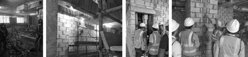
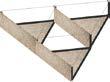
Guastavino Vault Workshop
Undergraduate [3rd Semester ] Group Workshop
About
Project Type
Location
Seating Structure Installation
Department of Architecture, College of Engineering, Trivandrum, Kerala, India
Year
Brief
2014
The objective was to construct a Guastavino vault inspired seating structure, designed by Ar. vinu daniel in the department of architecture courtyard The main purpose of the structure was to provide seating for the informal/formal gatherings that took place at the courtyard .

Architect Supervisor : Project Involvement :
Ar. Vinu Daniel On-site design execution
Be.m 10
39
E-Mail : bemathew1495@gmail.com Contact +44 - 7824049969 [ Bibin Mathew ] Be.m