Tunnelling into a Sustainable Future – Methods and Technologies – Johansson et al (Eds) © 2025 The Author(s), ISBN 978-1-032-90462-7
Open Access: www.taylorfrancis.com, CC BY-NC-ND 4.0 license

Tunnelling into a Sustainable Future – Methods and Technologies – Johansson et al (Eds) © 2025 The Author(s), ISBN 978-1-032-90462-7
Open Access: www.taylorfrancis.com, CC BY-NC-ND 4.0 license
A. Gope, P. Banerjee & A. Sur Ayesa India Private Limited, Noida, India
ABSTRACT: The Kanpur Underground Metro project faces challenges in a densely populated area with old buildings and aging brick sewer lines at shallow depths. Relocating these sewer lines was impractical, so the Tunnel Boring Machine (TBM) must pass beneath them. The area’s alluvial soil includes clay, silt, gravel, and sand, with a groundwater table 27m deep. To assess the impact of TBM tunneling, particularly where the TBM cover is under 3m, a two-dimensional Finite Element Analysis (FEM) was performed using PLAXIS 2D software. This paper presents a thorough analysis and proposes safe construction methods for TBM tunneling in these challenging conditions. The FEM results are validated through realtime data from on-site monitoring instrument.
As global population growth accelerates in densely populated urban areas, underground Metro Rail Transit Systems (MRTS) are increasingly vital for reducing travel times, alleviating traffic congestion, and minimizing noise and air pollution. Constructing underground stations in older, congested cities presents significant challenges, such as limited space and proximity to old structures, increasing public concern about ground movements from tunneling affecting nearby structures and utilities. These ground movements can deform structures, risking historic properties, causing disruptions, delays, and cost overruns. To address these issues, understanding the response of old structures to tunnel-induced movements, establishing reliable damage assessment methods, and implementing protective measures are essential.
This paper addresses the specific design challenges faced in Kanpur city, where significant old brick masonry sewer lines are present and require protection during tunnel boring machine (TBM) tunneling at shallow depths. We employed the widely accepted finite element method (FEM) software PLAXIS 2D to analyze the impact of TBM tunneling on these sewer lines, providing insights into effective management strategies for such infrastructure.
2.1 Project description
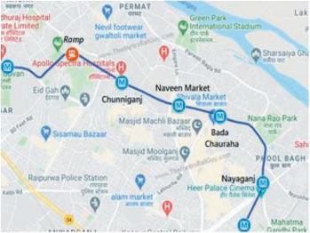
The first phase of the Kanpur city underground metro project (Contract KNPCC-05) is focused on constructing a 4.0 km underground metro line that will link four underground stations, including key commercial centers within Kanpur city, as illustrated in Figure 1.
The primary tunnels are constructed with a dual-tube design, each having an internal diameter of 5.8m, and they were dug out using an Earth Pressure Balance (EPB) Machine with a boring diameter of 6.55m. There are plans for a total of 8 Tunnel Boring Machine (TBM) breakthroughs. According to the most recent data available as of September 2024, All the TBM breakthroughs have been achieved. The introduction of the new metro system will enhance safety and promote a more business-friendly environment in Kanpur. This
DOI: 10.1201/9781003559047-354
environmentally friendly urban infrastructure, characterized by its low carbon footprint and climate resilience, will not only grant better access to essential services and employment opportunities but will also foster private sector growth while mitigating environmental harm. This initiative aligns with the core objectives: firstly, it addresses climate change by encouraging a shift from road to rail transportation, thereby reducing greenhouse gas emissions, and secondly, it contributes to the development of social and economic infrastructure, which is vital for urban progress. The Gulermak-Sam India JV Consortium serves as the primary contractor for the tunnelling activities within the scope of this contract under the client entity known as the Uttar Pradesh Metro Rail Corporation Limited (UPMRCL). Ayesa Ingenieria Y Arquitectura SA has overseen detailed design pertaining to underground structures, both permanent and temporary, as well as providing technical support throughout the construction process.
Kanpur city is situated within the Indo-Gangetic Plain, characterized by the predominant sedimentary components of alluvial soils, encompassing clay, silt, gravel, and various grades of sand. In some Groundwater tables were found to be deeper than 27m below the existing ground level, while for most of the alignments covered in this report, groundwater was not encountered. Consequently, the construction of TBM tunnels was expected to occur in dry or unsaturated alluvial soils.
The older alluvial deposits, primarily found in the central region, were formed during the Lower to Upper Pleistocene era. On the other hand, the newer alluvial deposits, which are mainly located along river courses, were deposited during the Upper Pleistocene to the Recent period. The district’s soil displays a diverse range of compositions and appearances. A significant portion of the area comprises common soils referred to locally as ‘Bhur’ and sandy soils on the ridges, ‘Matiyar’ or clay in low-lying areas, and ‘Domat’ or loam in the plains. In clay-rich areas, the ‘Reh’ soil type predominates.
In addition to the limited workspace, narrow and congested roads, and the limited number of boreholes, there are challenges associated with the presence of an old brick sewer line, which has a shallow cover of approximately 3.0m from the TBM crown and the current state of distress is uncertain.
Conducting a thorough inspection of the entire brick sewer line network and implementing temporary traffic diversions proved unfeasible due to its position beneath the primary city access route. In such circumstances, it is essential to perform a thorough analysis of ground movement, assuming the most challenging design parameters, in order to identify effective
engineering solutions for safeguarding the sewer line during tunnelling operations, thereby mitigating the risk of potential catastrophic failures on the surface.
Based on the data gathered from the site survey, there are specific locations of different tunnel drives where sections of the brick sewer line have been identified as potentially critical during TBM operations. The following analyze sections in Figure 2, Figure 3 and Figure 4, have been assessed for their potential impact on the alignment.

Figure 2. Analyze section 1 for impact assessment of brick sewer line (cover-2.917m).

Figure 3. Analyze section 2 for impact assessment of brick sewer line (cover-2.548m).

Figure 4. Analyze section 3 for impact assessment of brick sewer line (cover-3.936m).
Finite Element Analysis (FEM) in PLAXIS 2D software specifically designed for evaluating deformation and stability in geotechnical engineering applications. This analysis was carried out on specific critical sections to explore the possible impacts of the TBM tunnel construction
on the existing brick sewer line. A plain strain constitutive model was developed using 15 nodded triangular elements considering 160m wide and 80m deep cluster boundary based on the engineering judgement, ensuring that the tunnel construction’s impact remains within these limits. The upper boundary was kept free in both X and Y directions, the side boundaries are fixed in the X direction and free in the Y direction, while the bottom boundary was kept fixed in both X and Y directions. A finer mesh was used in proximity to the tunnel linings to obtain precise deformation values.
The mechanical characteristics of the soil are characterized by the Hardening Soil (HS) model, a constitutive law designed to consider the elevated soil stiffness seen at low strain, its alteration with strain levels, and the initial accumulation of plastic deformations, as noted by Schanz et al. in 1999. The Hardening Soil model is an advanced approach used to replicate the behavior of various soil types, encompassing both soft and stiff soils. The soil’s elastic properties are determined through isotropic elasticity, utilizing Young’s modulus that depends on stress for unloading and reloading stress paths. This modulus is a function of the effective stress and strength parameters.
The geotechnical parameters of the critical sections are considered by relying on the data obtained from boreholes in the field and laboratory tests. The conservative design parameters have been opted for different tunnel drives because of the limited available data and are given in Table 1, Table 2 and Table 3.
1. Geotechnical parameters for analyze section 1.
Table 2. Geotechnical parameters for analyze section 2.
Table 3. Geotechnical parameters for analyze section 3.
Since the tunnel rings consist of jointed segments with a thickness of 275mm, the simulation of the tunnel linings was performed using plate elements, taking into account the effective (reduced) moment of inertia for joints effect of segments as proposed by Muir Wood in 1975. The brick sewer line was modelled with elastic cluster material. The brick properties were assumed on the conservative side as per the literature “Characterization, damage and repair of brick masonry, by Paulo B. Lourenco et. al.” The structural parameters are provided in Table 4 below.
Table 4. Structural parameters for analyze section 1, section 2 and section 3.
5.3 Construction sequence
In the FEM analysis, the construction stages were defined assuming that the brick barrel and lining are wished-in-place. The representative construction stages are outlined as follows:
• Initial phase to generate in-situ stresses at ground.
• Brick sewer line installation (wished-in-place).
• Application of ground surcharge of 24 kPa for traffic loading.
• Resetting the displacement and installing the right-hand side (RHS) tunnel in a pre-defined condition with line contraction, equivalent to a conservative volume loss of 0.7%.
• Installing the left-hand side (LHS) tunnel lining in a pre-defined condition with line contraction, resulting in a conservative volume loss of 0.7%.
The primary concern revolves around ground settlements near the brick sewer line and their potential impact on the sewer system. The Finite Element Method (FEM) analysis results, specifically the vertical ground deformations or settlements bears a resemblance to a chimney shape, extending towards the surface. There is a possibility for these chimney-like settlements to reach the surface, potentially affecting the sewer system and
causing surface disturbances. In addition to vertical settlement, horizontal deformation is also obtained, which has a considerable impact on structural deterioration. The angular distortion and assessment of tensile strain below the brick sewer line was conducted according to the FEM analysis results, following the principles outlined in Burland et. al (1995) and Boscardin and Cording (1989). Longitudinal settlement is also obtained considering the anticipated minimum and maximum face-pressure during tunnelling operation. Below are the results obtained from the analysis performed using the Finite Element Method (FEM) shown in Figure 5 to 9.


min=21mm).
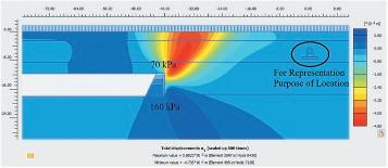
Figure 8. Sample critical brick sewer line longitudinal settlement during tunneling with minimum face-pressure for section 3 (max=5mm, min=1mm).

Figure 9. Sample critical brick sewer line longitudinal settlement during tunneling with maximum face-pressure for section 3 (max=2mm, min=1mm).
Table 5. Summary of settlement and impact assessment.
Description
The summary outlined in Table 5 can be derived from the FEM results presented earlier. Considering the expected ‘negligible’ damage category after the impact assessment, it is improbable that the brick sewer line will encounter abrupt instability or serviceability problems.
Instrumentation and monitoring are vital for ensuring safe tunneling and identifying collapse risks in challenging conditions. To achieve precise measurements of surface vertical deformation and the movement of the surrounding ground, a comprehensive instrumentation strategy was recommended. This approach involves deploying surface settlement markers, inclinometers, and rod extensometers within the specified areas of analyze section 1, section 2,
and section 3 to observe surface settlement and ground movement near the brick sewer line. The monitoring trigger limits have been established in accordance with Table 5. Upon tunnel drives completion, the maximum observed surface vertical settlement at the ground settlement markers for analyze sections 1, section 2, and section 3 were 4 mm, 5 mm, and 8 mm, respectively. Horizontal deformation of 1 mm was recorded in the inclinometer at all three sections, and 1 mm of deformation was also noted in the rod extensometer for all three sections.
This paper examines the impact of ground movements induced by tunneling on nearby old brick sewer lines situated less than 3.0 meters from the tunnel boring machine (TBM) crown. It highlights the importance of soil-structure interactions and discusses a damage criterion based on strain conditions. A comprehensive assessment procedure for evaluating structural damage due to tunneling has been outlined, taking into account the influence of these interactions.
Analysis of key tunnel sections revealed a maximum expected settlement of 23 mm beneath the brick barrel foundation, corresponding to a 0.7% volume loss in soil during tunneling. Given the uncertain condition of the sewer line, additional measurements and TAM grouting either from the surface or directly at the TBM face are recommended when the distance between the TBM crown and the sewer line invert is less than 3.0m, despite categorizing tunneling-related damage as ‘negligible.’
Recommendations for ground improvement may be adjusted based on insights from previous TBM drives and ongoing monitoring data. Maintaining appropriate face pressure and ensuring high-quality annular grouting around TBM segments are crucial for minimizing volume loss during tunneling, which will help reduce settlement beneath the brick sewer line. Rigorous site monitoring is essential, particularly in shallow cover zones.
It was noted that ground improvement through surface grouting was not executed in alignment with TBM performance during initial drives, due to site constraints in this densely populated area. Post-tunneling monitoring indicated a maximum surface settlement of 8 mm and horizontal ground deformation of 1 mm across critical sections, with no reported damage to the old brick sewer line and surrounding structures at surface. These findings reinforce the effectiveness of the proposed strategies and highlight the importance of careful planning and monitoring in urban tunneling projects.
Clough. G. W. and A. I. Mana. “Lessons learned in finite element analyses of temporary excavations in soft clay.” This paper was presented and discussed at the 2nd International Conference on Numeric Methods in Geomechanics, held in Virginia Polytechnical Institute and State University, Blacksburg, June 1976, Vol. 1. No. Proceeding, 1976.
Burland, J. B., & Wroth, C. P. (1995). “Settlement of buildings and the influence of tunneling.”
Boscardin, M. D., & Cording, E. J. (1989). “Building response to excavation-induced settlement.” Journal of Geotechnical Engineering, 115(1), 1–21.
Franzius. Jan N. David M. Potts. and John B. Burland. “The response of surface structures to tunnel construction.” Proceedings of the Institution of Civil Engineers-Geotechnical Engineering 159.1, 2006, pp. 3–17.
Lourenço. P.B., van Hees, R., Fernandes, F., Lubelli, B. “Characterization and Damage of Brick Masonry” In: Costa, A., Guedes, J., Varum, H. ( eds ) Structural Rehabilitation of Old Buildings. Building Pathology and Rehabilitation, vol 2. Springer, Berlin, Heidelberg., 2014.
Rankin. W. J. “Ground movements resulting from urban tunnelling: predictions and effects.” Geological Society, London, Engineering Geology Special Publications 5.1, 1988, pp. 79–92.
Schanz, T.P.A. Vermeer, and P. Gc Bonnier. “The hardening soil model: formulation and verification.” Beyond 2000 in computational geotechnics 1, 1999, pp. 281–296.
Wood, AM Muir. “The circular tunnel in elastic ground.” Geotechnique 25.1, 1975, pp. 115–127.
PLAXIS 2D (2022) “Reference Manual”.