The Official Publication of the AUGI Design Community October 2023 Diamond Sponsors Color Schemes – Not Just for Architects | Reflections on a Decade of Training and Education in AECO AUGIWORLD Also in this issue: Customizing Your Workflow


augi.com/augiworld October 2023 | AUGIWORLD Magazine 3 CONTENTS 14 20 34 October 2023 AUGIWORLD FEATURES 6 Artificial Intelligence 6 Ways Business Leaders Can Leverage an AI Image Generator 8 Color Schemes Color Schemes – Not Just for Architects 12 Corporate Growth Customizing Your Plans For Future Success – Keep It Real! 14 SOLIDWORKS Mechanisms & Mentorship: CAD Video Game Accessory 20 ARES Kudo Online CAD in DWG: ARES Kudo Is Connecting Projects and People to Work Anywhere and More Efficiently 26 Training Reflections on a Decade of Training and Education in AECO 30 BricsCAD BricsCAD Customizations 34 LISP Commands Free Samples– The Halloween Edition COLUMNS 4 Letter from the Editor 18 Inside Track 24 Tech Manager
Letter from the Editor
This issue of AUGIWORLD focuses on customization. At my current job, we have a lot of customization we house in the Tool Palette. We moved our customization from the ribbon and housed it in the Tool Palette a couple of releases back. This has streamlined our processes very efficiently.
When we think about customization, we usually think about the appearance of our workspace. However, customization reaches far beyond just the appearance of your current workspace. It also includes programs inside of your software. For example, we had a program written for our Civil 3D environment that will alert the user if they do not have a coordinate system set in the drawing. You have two options: Set the Coordinate System, or Do Not Set at This Time. If you choose to ignore it, close the drawing and open it back up, then you have three options: Set the Coordinate System, Do Not Set at This Time, or Never Alert for This Drawing Again. The reason for the third option is for publishing purposes. When publising a set a drawings, it’s important that it doesn’t hang and on drawings such as details, general notes, etc. This option allows the Publish command to carry on without interruption.
It’s important to note that Configuration and Customization are two different definitions. Configuration occurs during the implementation process and does not affect any part of how the software operates. Customization, on the other hand, requires fundamental changes to the baseline of your workspace in which there may be functionality that is missing.
I hope you readers get a lot from this issue and can use some of the customization to help with your daily workflows.
Editor-in-Chief
www.augi.com
Editors
Editor-in-Chief
Todd Rogers - todd.rogers@augi.com
Copy Editor
Isabella Andresen - isabella.andresen@augi.com
Layout Editor
Tim Varnau - tim.varnau@augi.com
Content Managers
3ds Max - Brian Chapman
AutoCAD - Mathew Marrero
Civil 3D - Shawn Herring
BIM/CIM - Stephen Walz
BricsCAD - Craig Swearingen
Dassault Systèmes - Rafael Testai
Electrical - Mark Behrens
Manufacturing - Kristina Youngblut
Revit - Jason Peckovitch
Tech Manager - Mark Kiker
Inside Track - Shaun Bryant
Advertising / Reprint Sales
Kevin Merritt - salesmanager@augi.com

AUGI Executive Team
President
KaDe King
Vice-President
Frank Mayfield Treasurer
Todd Rogers
AUGI Board of Directors
Eric DeLeon
KaDe King
Chris Lindner
Frank Mayfield
Todd Rogers
Scott Wilcox
Kristina Youngblut
Publication Information
AUGIWORLD magazine is a benefit of specific AUGI membership plans. Direct magazine subscriptions are not available. Please visit www.augi.com/account/register to join or upgrade your membership to receive AUGIWORLD magazine in print. To manage your AUGI membership and address, please visit www.augi. com/account. For all other magazine inquires please contact augiworld@augi.com
Published by:
AUGIWORLD is published by AUGI, Inc. AUGI makes no warranty for the use of its products and assumes no responsibility for any errors which may appear in this publication nor does it make a commitment to update the information contained herein.
AUGIWORLD is Copyright ©2023 AUGI. No information in this magazine may be reproduced without expressed written permission from AUGI.
All registered trademarks and trademarks included in this magazine are held by their respective companies. Every attempt was made to include all trademarks and registered trademarks where indicated by their companies.
AUGIWORLD (San Francisco, Calif.)
ISSN 2163-7547
AUGIWORLD Magazine | October 2023 augi.com 4
AUGIWORLD


A Global Community for AEC Professionals to Learn, Grow and Exchange Knowledge. Become a member: www.dbei.org/membership
6 Ways Business Leaders Can Leverage an AI Image Generator
Generative artificial intelligence is streamlining operations for companies in all kinds of industries. Business leaders are employing ChatGPT for social media content creation, adding AI chatbots to their websites to answer visitors’ questions, using AI to create 3D models of new product ideas, and so on. And now there is a whole new AI realm that companies will find very useful for marketing strategies and other tasks: AI image generators.
Using artificial intelligence to create customized images can really help business leaders cut costs and speed up all kinds of initiatives. In my experience as the founder of the 88stacks AI image generator (which provides easy-to-use and affordable tools to democratize access to generative modeling and images), I have discovered many ways AI photo generators help businesses reach new heights. Here are 6 of them to explore:
COST-EFFECTIVE ONLINE MARKETING MATERIALS
In today’s digital era, there’s no doubt that online marketing is paramount for new and established businesses to grow. Companies pay marketers large sums of money to create images for Google ads, email blasts, infographics to send to media outlets for a possible feature, and other online marketing assets. This no longer needs to be the case! AI image generators can help alleviate the cost that comes with employing professionals to create online marketing materials. Business leaders can simply input text that describes how they want an
image or infographic to look like into an AI image generator, and it will create that exact graphic.
TIMESAVING & VERSATILE SOCIAL MEDIA CONTENT CREATION

Going off of the last point, a robust and consistent social media strategy is also essential for businesses. It is important to have a great mix of promotional content and social media posts that are fun and/or provide free value. For example, there are always new memes and trends that companies should try to take part in to grow their followers and gain potential customers. Luckily, AI image generators can be used to create custom graphics for Instagram, Facebook, etc. It is much faster than traditional design methods, enabling business leaders to produce content more efficiently, meet tight deadlines, and take part in trends before they fizzle out.
TARGETED EMAIL CAMPAIGNS
Should a business send the same promotional email blast to both regular consumers and business customers? No, as creating targeted email campaigns will maximize the effectiveness with both customer segments. Business leaders can use AI image generators to create visuals that are tailored to specific audience segments, which in turn will increase the conversion rate of each email marketing campaign.
For example, an email blast sent to regular consumers can show an image of a family using the brand’s product in a house, and an email blast sent to business customers can show a company
AUGIWORLD Magazine | October 2023 augi.com 6 by: Jason Toy Artificial Intelligence
leader using the same product in an office space. On top of this, an AI image generator can even incorporate each customer’s name into the image shown in the email blast sent to them. All of these personalization elements can really enhance the appeal and memorability of each email blast, which can contribute to long-term brand recognition and conversions.

EFFORTLESS GRAPHIC DESIGN FOR PRINT
Companies spend so much money paying graphic designers to create custom images for promotional flyers, posters, and other print materials. Businesses may also think it is more cost-effective in the long run to purchase pricey graphic design software that is highly technical and confusing. However, they then waste so much valuable time trying to figure out how to use this software. With an AI image generator, business leaders can create a ton of high level and quality-driven visuals at a fraction of the cost and without the technical and creative demand of graphic design and related software.
PERSONALIZED BRANDING
In virtually every industry, having a strong and recognizable brand is vital for businesses to grow their share of the market. Branding elements like a specific color scheme, unique font, and logo can really help set a business apart from its competitors and add to the overall appeal of the company. This in turn can help make the business top of mind when a potential customer is in the market for products and/or services that company provides. Think about it — when you are driving home from work and are in the mood for a cheap, quick, and tasty hamburger, you might think of easily recognizable brands like Wendy’s or McDonald’s.
That all said, an AI image generator can produce custom visuals that align with a brand’s unique identity, fostering stronger brand recognition and customer loyalty. For example, an AI image generator can follow predefined style guidelines to create unique infographics and images for social media and Google Ads that align with a company’s overall brand tone, website aesthetics, and message about the mission it is trying to achieve.
A/B TESTING VISUALS FOR OPTIMAL MARKETING RESULTS
A/B testing is pivotal for ensuring each marketing initiative is as effective as possible at growing sales. From variations of the copy used in Google
Ads to trying out different scripts for cold calls to sales leads, A/B testing can help business owners pinpoint the best marketing elements to use. An AI image generator can help with this! Business leaders can use an AI image generator to quickly and easily create variations of visuals to conduct A/B testing, thus optimizing marketing efforts based on data-driven insights.
For example, a cat products company can use an AI image generator to create various images that each show a different cat playing with a brand-new toy launch. All of these images can be tested in online ads, and the one that leads to the most clicks can be used for all ads.
TO WRAP IT ALL UP
AI image generators are revolutionizing the way companies operate. For example, an AI image generator can help business leaders create costeffective online marketing materials and save a lot of time on producing versatile social media content. An AI image generator can also create effortless graphics for print materials and make it a breeze to A/B test visuals for optimal marketing impact. These are just a few ways how company leaders can leverage an AI image generator to boost their overall business success.
Jason Toy is the founder of the 88stacks AI image generator, which provides easy-to-use and affordable tools to democratize access to generative modeling and images. Jason believes that everyone should have the opportunity to explore and create with generative technology, regardless of their technical background or expertise. To achieve this goal, 88stacks is dedicated to developing innovative solutions that simplify the process of generative modeling and image creation, while also offering comprehensive training and support to our users. Jason has a strong passion for machine learning and artificial intelligence, where he has contributed significantly to both practical implementation and cutting-edge research.
www.88stacks.com
augi.com/augiworld October 2023 | AUGIWORLD Magazine 7
Artificial Intelligence
Color Schemes –Not Just for Architects

Customization in Autodesk Revit allows users to tailor the software to their specific needs and workflow. This can range from customizing the user interface to creating custom families, templates, or even adding new features through add-ins. Using native Revit functionality, your project team, whether it’s someone with BIM in their title or your design staff can customize the way Color Schemes are used. Today, I will be discussing how I have used Color Schemes to help with our everyday MEP designs. If you are in the Architectural field, you are probably using Color Schemes primarily for visualization and presentation purposes to enhance the understanding and communication of your design concepts. Color Schemes can be applied to Rooms, Areas, Spaces or Zones and Pipes or Ducts. For those that are not sure what Color Schemes are, a color scheme is a tool used to visually represent and differentiate elements or properties within
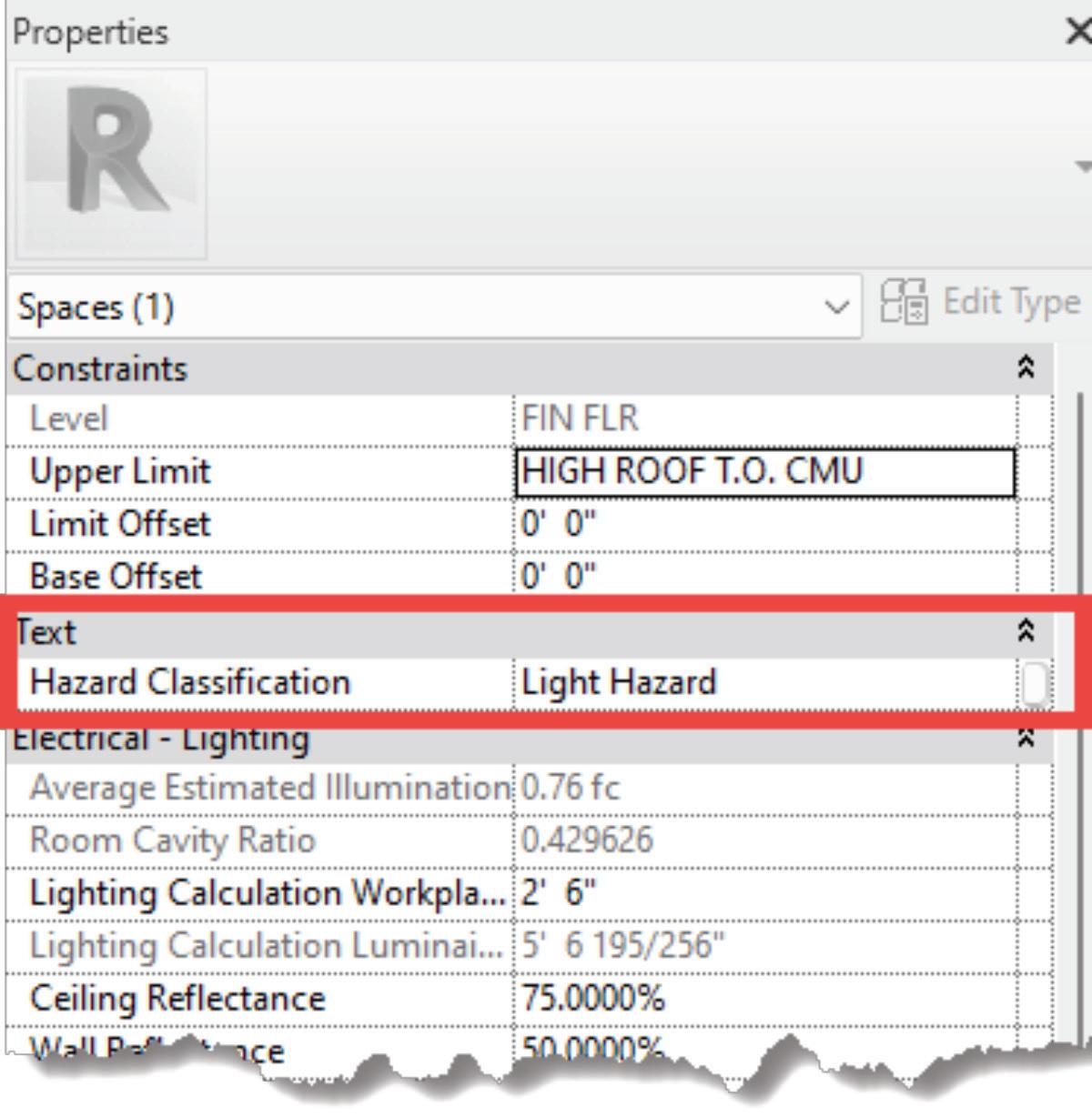
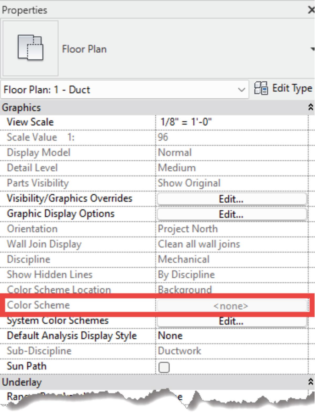
a building model. Color schemes are often used to improve the readability and understanding of a project, especially in large and complex architectural designs. They allow you to assign colors to various elements or parameters, making it easier to identify and analyze specific information within your Revit model. It can be found on the properties palette under Graphics which can be controlled by a View Template or independently per View. It is grayed out in the screenshot below because it is controlled by a View Template.
In my 15+ years in the industry, I’ve only used Color Schemes for MEP at the first company I worked at back in Denver 15 years ago. More on that later. At the companies since, I have not used Color Schemes until now which is what this article is about. I bet you are asking yourself what I have used Color Schemes for in our MEP Designs. Below you will find 3 examples of what I am using Color
AUGIWORLD Magazine | October 2023 augi.com 8 Revit
by: Jason Peckovitch
Schemes for. The key to using Color Schemes in these examples is Spaces, without them, this does not work very well.
HAZARD CLASSIFICATIONS
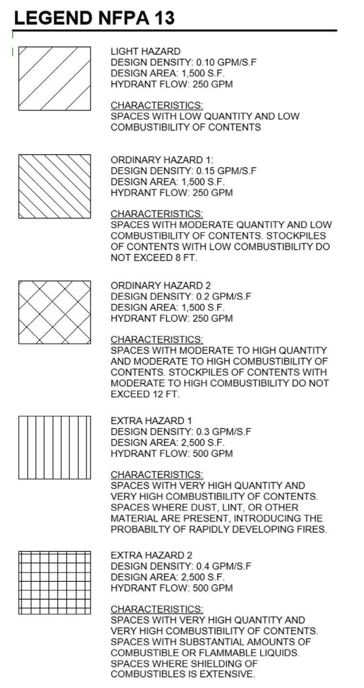
Before I started here at Garver, they were not creating MEP Spaces in their models. This is now required as part of our model creation/ setup process to have Space created. The current process for showing the Fire Protection Hazard Classifications is to manually add these using a Filled Region with the same name as the Hazard Classification as defined by NFPA 13, see Figure 2.
This process, while effective, can be quite time consuming, especially when multiple views/levels are present in the Revit model. By utilizing MEP Spaces, I have created a custom Shared Parameter called Hazard Classification that has been added to our MEP Template as a Project Parameter and applied to Spaces. Once created, Spaces are then selected, individually or by Hazard Classification and the Hazard Classification is typed in, copied, or selected from the drop down.
augi.com/augiworld October 2023 | AUGIWORLD Magazine 9 Revit
Figure 1
Figure 2
Figure 3
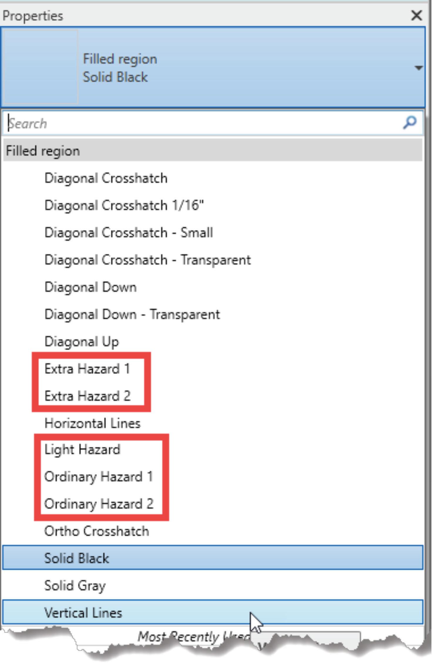
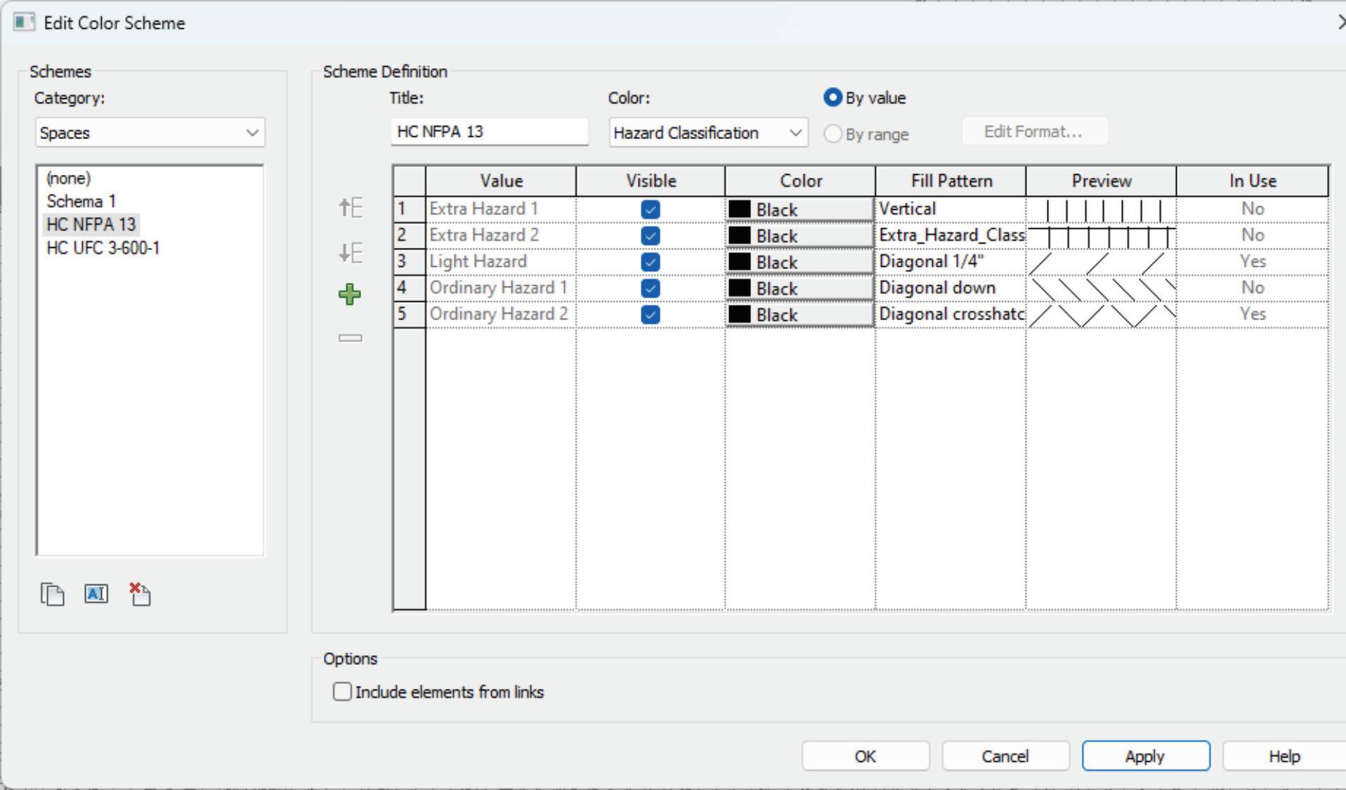
The customization does not stop there. In order to see those classifications identified in the views, you will need to create the Color Scheme(s). I have created 2 different Color Schemes to visualize the Hazard Classification of choice depending on the project: HC NFPA 13 and HC UFC 3-600-1. Each are slightly different and the one shown in the screenshot is HC NFPA 13. As you can see, it is set up to utilize colors based on the selected Parameter, Hazard Classification and “By value”. While I am currently just using the color black (because we don’t print in color), the fill patterns matters here.
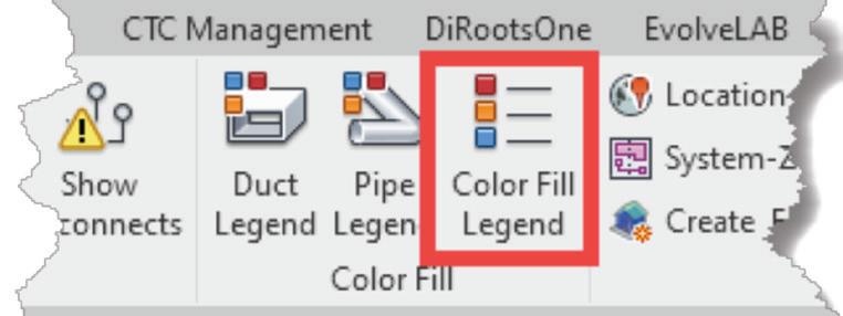
Lastly, you will need a Legend of sorts to help your client identify what each of these fill patterns mean. I see 2 options for accomplishing this. The first being, using the Color Fill Legend found on the Analyze Tab of Revit or creating a custom legend. When using the Color Fill Legend, it will not show you anything until that parameter is filled out and will not give you anything other than the Hazard Name used in the Color Scheme. Therefore, it cannot really be customized unless that Color Scheme value is expanded more. By utilizing a Legend, you can customize it however you see fit which is what I would recommend.
LIGHTING CONTROLS
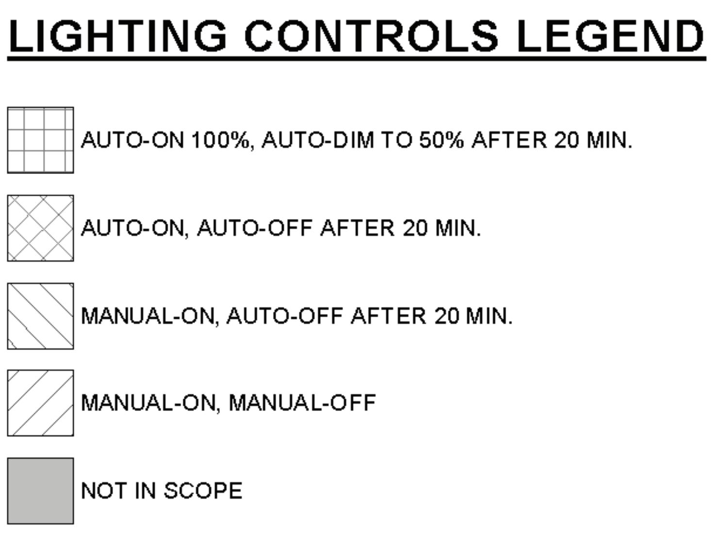
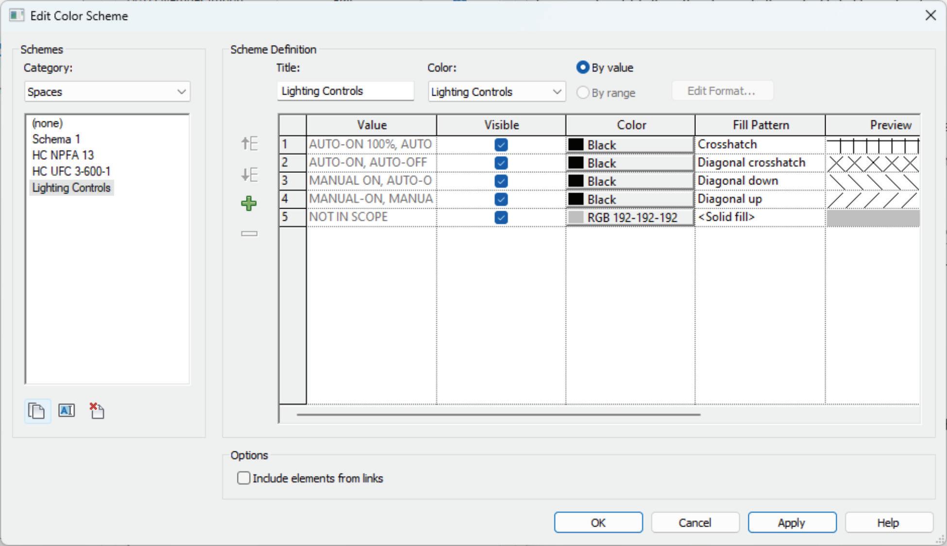
Similarly, to Hazard Classification above, a custom Shared Parameter called Lighting Controls was used and applied to our Spaces. I have also created a Color Scheme and a custom View Template of the same name that is assigned to a set of floor plan views in our MEPF template that may or may not be on every project. At the time of this writing, some of the Fill Patterns are the same as the ones used for Hazard Classification and will probably expand the fill pattern list to create specific ones at a later date so they don’t accidentally get modified.
Unlike the Hazard Classification, I am using the Color Fill Legend from Revit because the Value, as seen in the screenshot, is detailed enough for the Lighting Controls plans. As I mentioned previously, if you want to customize this more and add more information, by all means use a Revit Legend instead of the Color Fill Legend.
ELECTRICAL ROOMS
Remember when I said, “more on that later”, well let me expand on that now. Back when I first started using Revit in 2007, the company I
AUGIWORLD Magazine | October 2023 augi.com 10 Revit
Figure 4
Figure 5
Figure 6
in those locations. Now, some customization to that Color Scheme may be needed as necessary because, you know, no two Architect’s do the same thing or call things the same. That method worked great for us and became the new standard while I worked there. What surprised me was that no one else was visually identifying the Electrical Rooms in their views at the few companies I have worked at since.
CONCLUSION
I hope that I sparked some creativity. What thoughts are now running through your head about what you can use Color Schemes for in your Designs? Remember that while customization can enhance your workflow and improve efficiency, it’s essential to maintain a balance. Excessive customization can lead to compatibility issues and make it challenging to collaborate with others who may not have the same customizations. Always document your customizations and backup your settings to ensure you can restore them if needed.
worked for was adding Hatch patterns to the CAD backgrounds they received from Architects to help the design staff visually identify where Electrical Rooms were located so they would not run their duct or pipe through those rooms. Revit for MEP was still in its infancy at that time and not all that great to use for MEP honestly so at the time, I had no idea how I was going to accomplish that. After a lot of exhaustive searching, I came across Color Schemes, but it was only being used by Architects. I quickly learned that I could create a space, use the spacing naming utility to that the space had the same name as the Architectural room. I then created a new Color Scheme, probably called Elec Rooms or something, that looked for the space name that contained a few variants like Electrical or Elec which then applies a specific hatch pattern
Jason Peckovitch is an Autodesk Revit Certified Professional for Mechanical and Electrical Design located in SE Iowa. He is a BIM Manager for Garver’s Buildings Business Unit, specifically MEPF. Garver has nearly 50 offices across the United States and more than 1200 employees. His CAD/BIM career spans over 25 years but he didn’t switch to the AEC Industry until 2007 as a Mechanical HVAC Drafter and transitioned into BIM Management shortly after where he has been working since. Jason is also the father of three pre-teen children, a published photographer, gamer, and car/tech guy. He can be reached at jmpeckovitch@ garverusa.com.

augi.com/augiworld October 2023 | AUGIWORLD Magazine 11 Revit
Figure 7
Figure 8
Customizing Your Plans For Future Success – Keep It Real!

SETTING ATTAINABLE GOALS FOR CORPORATE GROWTH

Acommon goal among all businesses, regardless of size, is to grow and prosper. This will require a well-researched and carefully executed plan based on each business’s unique environment.

If I could develop a plan that would universally assure prosperity and growth for any business, I would never have to work again.
Every organization has a culture that is truly their own. This creates great diversity in every industry. Smaller organizations, as well as large corporations, co-exist in any industry.
Growth and profitability are common threads among both small and large organizations. These activities must take many factors into account.
Shooting for the stars will cause you to come crashing back to earth. However, not aiming high enough will stop you from getting into orbit. There is a fine line, which, as we walk will lead to corporate success.

WHAT DEFINES AN ATTAINABLE PLAN
Any organization, with the proper time investment and research done early on, can establish a practical
and attainable plan to move forward and grow.
CHALLENGES TO BUILDING FUTURE SUCCESS
Every organization has its own unique set of available resources. Identifying and categorizing them accurately is critical.
A plan for corporate success will require identifying not only the strengths but also the weaknesses unique to that group.
The first step in any future planning is to review past efforts. This needs to be done honestly, with the mindset that past efforts are, regardless of success, lessons learned for the future.
The mindset of those planning for future progress must be open to accepting that they may have been involved in past less than successful efforts.
AUGIWORLD Magazine | October 2023 augi.com 12 Corporate Growth by: Mark Behrens
KEEPING YOUR FUTURE GROWTH PLANS ACHIEVABLE
Every organization has a management plan and corporate culture all their own. Then there are the OG’s (original gangsters), having been the company’s backbone for many years, who have seen many changes in this culture. As new faces join the group, differing mindsets will undoubtedly be considered.
Another factor to consider is data management. You cannot reliably jump into cloud computing and AI with a shaky infrastructure or poor data management plan.
Fine-tuning an organization’s future will require considering all this and honestly evaluating each of these things on their own merit and reliability.
The OG’s will not embrace AI (Artificial Intelligence) and its benefits, as will the new hires. The new hires, typically of the “Google it” mindset, will not want to know the old-school method of solving an issue.
If the corporate mindset only embraces the future as the end-all, as many organizations do in a cookiecutter plan, there will not be much success.
In the same way, not accepting the experience of senior employee solutions will overlook tried and true methodology. Alienating either end of the employee spectrum will be an instant failure.
Creating a committee to blend experience levels and new and old technologies is a solid start. A word of caution is in order, however. Every committee member will have an additional potentially dissenting opinion to deal with.

Keeping to key people is best, with these key people bringing the feedback of their respective co-workers to the table.
CONCLUSION
In today’s ever-changing environment, achieving forward progress can be challenging. Having been in the design industry for forty years, I have seen many changes. I have been part of some and excluded from some, depending on my employer at the time.

The biggest roadblock I have seen is an organization not being open to an idea or feedback from its internal resources.
The mindset that “this plan worked for other people means that it is best for us too” has led to more internal dissension and confusion than anything else.
Realizing that your organization is not the same as the next. and learning your weaknesses and strong points is imperative. Your unique staff and corporate structure must be the basis of how you develop forward-thinking plans.
Any plan that is established must also be a living process. Regular review of progress and issues developed must be part of the plan. Just look at how COVID upended things.

Having a dynamic and open mindset will allow your resources, as they change and mature over time, to keep your business moving forward and grow as the industry expands, even with the volatile environment we are currently in.
Mark Behrens' employer designs Automated Guided Vehicles (AGV’s) and test machines. He has worked with AutoCAD software for forty years, starting on version 1.4. Having been with his current employer for almost sixteen years and CAD manager by necessity for at least ten, he has seen their culture change many times in attempts to improve processes and become more efficient. CAD standards have become a high-profile topic recently. Mark is excited to share his process of implementing a user-friendly system of CAD standards with others.
augi.com/augiworld October 2023 | AUGIWORLD Magazine 13 Corporate Growth
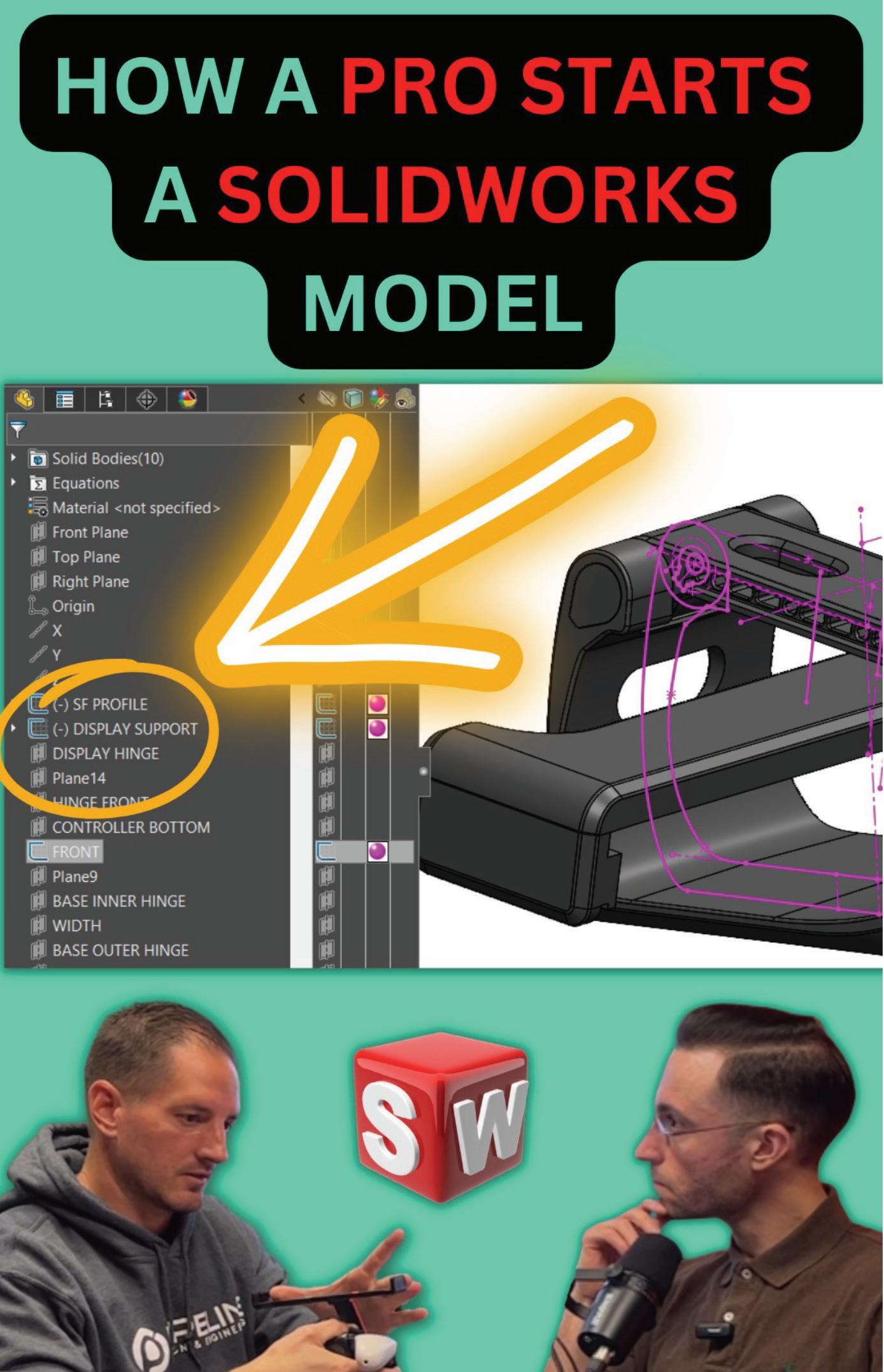
Mechanisms & Mentorship: CAD Video Game Accessory
THIS ARTICLE IS BEST READ AND VIEWED IN THE ELECRONIC VERSION OF AUGIWORLD
https://youtu.be/Q2FzWFyj0LE
Ever wondered what it would be like to be mentored one-on-one by a senior engineer that’s using SOLIDWORKS to successfully deliver solutions to industry clients? My name is Rafael Testai, and in this video series, Mechanisms & Mentorship, we’ll take a look behind the scenes to see how a hand-picked engineer has designed one of their mechanisms in granular detail. We’ll “open the hood” to analyze their CAD design and thought process behind the solution. I’ll ask them questions about the project, roadblocks, challenges, specific insights they learned, and how they’re using SOLIDWORKS to solve real world problems.
You’ll learn a mixture of soft skills and hard skills. This series is perfect for viewers who are already proficient in SOLIDWORKS (CSWA, CSWP, CSWE) and want to take the next step in their careers.
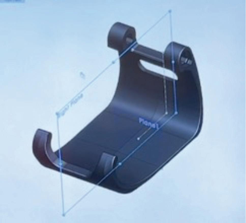
In this episode of Mechanisms & Mentorship, I’ll interview Industrial Designer Craig Ovans from TeamPipeline.us in Arizona. We’ll focus on the industrial design involved in the gaming accessory connected to the controller in Figure 1.
To watch reels, subscribe to Rafael Testai’s YouTube channel

AUGIWORLD Magazine | October 2023 augi.com 14 SOLIDWORKS by: Rafael Testai
SOLIDWORKS
TIME STAMPS:
What’s the Design Criteria? (Min 0:39) Craig explains how the accessory had to be handheld, stand by itself on a flat surface, and be adjustable.


What Led You in This Design Direction? (Min 2:10) Craig explains the dimensions that drove the design.
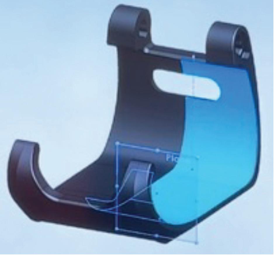
How to Conceal a Hinge? (Min 3:07)
Ovens explains how they didn’t want the hinges exposed. Hence, a clever solution was designed.
How to Design for Manufacturing? (Min 3:48) The challenge involved in this design was the undercut that would be present in the tooling.
augi.com/augiworld October 2023 | AUGIWORLD Magazine 15
Figure 1
Figure 2
How a PRO Starts a SOLIDWORKS Model? (Min 5:31)
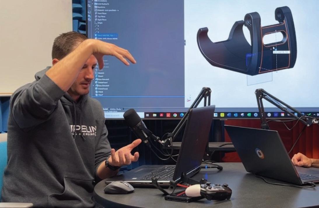
Start with the driving dimensions, the things you know won’t change. Next, add dimensions that will change. It’s key that you have these dimensions in skeleton sketches at the very top of your feature tree, so you can convert them later on as you begin modeling the solid bodies. To learn more about skeleton sketches, you may want to consider looking into RCM.
To watch reels, subscribe to Rafael Testai’s YouTube channel
To learn more about Craig Ovans, visit his LinkedIn.

If you read until the very end, I greatly appreciate it. I would encourage you to follow me on Linkedin so that we can stay in touch, and you can be notified when more articles like this one get published. I lead with value and my writing style is direct and to the point.
https://www.linkedin.com/in/testai/
Any recommendations on who you think I should interview next? Feel free to reach out to me on Linkedin or Instagram. I read all correspondence. Linkedin: https://www.linkedin.com/in/testai/ Instagram: https://www.instagram.com/rafael_ testai/
More: https://linktr.ee/testai
RAFAEL TESTAI
SolidWorks Influencer.
FOLLOW to watch exclusive videos I create that quickly teach you the inner working mechanism of interesting products l Mechanical Product Designer l LinkedIn/Instagram/ TikTok/Podcast/More articles: https://linktr.ee/testai
AUGIWORLD Magazine | October 2023 augi.com 16 SOLIDWORKS
Figure 3
Figure 4


AUGIWORLD Print AUGI HotNews Digital Visit www.AUGI.com/advertise Connect with AUGI Members Increase your revenue by advertising with AUGI and reaching its 400,000 Members. AUGI.com Website Thousands of visits per month Forum Advertising Active membership participation • Advertising Email Blasts • Targeted Mailings • Industry Leading Google Results Site US $8.00 The Official Publication of the AUGI Design Community Diamond Sponsors Implementing Best Strategies Automating Punch Lists with Bluebeam Revu Setting Up System Variables for Success in AutoCAD AUGIWORLD Also in this issue:
This month’s topic is Customization, so we have some apps from the App Store that allow you to customize your workflows and make your daily Autodesk application use that little bit more productive. Sometimes though, you may have a specific customization tool in mind, so make sure you search the store, as I’m sure you will find many apps that will customize your processes within your Autodesk applications and help you work smarter, not harder.
So, on that note, here are this month’s opportunities to advance your skills, processes, and workflows with the most current industry-related software and hardware updates available.
CUSTOM RANDOM PLANK HATCHES
https://apps.autodesk.com/ACD/en/Detail/Ind ex?id=4517915295381830122&appLang=en&os= Win32_64
Autodesk AutoCAD
Version: 2023, 2022, 2021, 2020, 2019, 2018
Autodesk AutoCAD Electrical
Version: 2023, 2022, 2021, 2020, 2019, 2018
Autodesk AutoCAD Mechanical
Version: 2023, 2022, 2021, 2020, 2019, 2018
Autodesk AutoCAD Architecture
Version: 2023, 2022, 2021, 2020, 2019, 2018
Autodesk AutoCAD MEP
Version: 2023, 2022, 2021, 2020, 2019, 2018
Autodesk® Civil 3D®
Version: 2023, 2022, 2021, 2020, 2019, 2018
Autodesk AutoCAD Map 3D
Version: 2023, 2022, 2021, 2020, 2019, 2018
Autodesk AutoCAD Plant 3D
Version: 2023, 2022, 2021, 2020, 2019, 2018
The Custom Plank Hatch Patterns for Autodesk® AutoCAD® give you ten common plank widths. They give the user the look of random tongue and groove flooring, as well as plank flooring.
These hatch patterns are compatible with AutoCAD and its vertical products. This app provides those plank patterns that we always need at some point when using AutoCAD!

CUSTOM SCREW CREATOR
https://apps.autodesk.com/FUSION/en/Detail/ Index?id=79972190430973837&appLang=en& os=Win64
Fusion 360
You can define your customized screw in this app with the following parameters:

Screw Name: Name of the Body
• Head Diameter: The diameter of the cylinder head
• Body Diameter: The diameter of the body shaft
Head Height: Height of the cylinder head
• Body Length: length of the body shaft
• Hexagon Diameter: Diameter of the inner Circle of the hexagonal polygon
• Hexagon Height: Height to cut the hexagon from the cylinder head
Fillet Radius: Radius of all fillets
• Thread Length: length of the thread
• Chamfer Distance: distance of the 45degree chamfer on the body shaft
• Or select preset values in the app
We all want to create custom screw sizes in Fusion 360. Here’s the app you need to do it!
MANAGE AXES
https://apps.autodesk.com/FORMIT/en/Detail/ Index?id=4262261326934031753&appLang=en &os=Web

FormIt
Version: 2022
This is an Autodesk-developed tool to customize the local coordinate system.
It features:
Align the local coordinate system workplane with the selected face
• Easily access the Set Axes Manually
• Resets Axes to Default tools
If you use FormIt on a regular basis in conjunction with Revit, you should be using this app. It’s a great way of customizing your axes!
AUGIWORLD Magazine | October 2023 augi.com 18 Inside Track by:
Bryant
Shaun
QUICK ROTATE
https://apps.autodesk.com/RVT/en/Detail/Inde
x?id=7370580827984278858&appLang=en&os =Win64

Autodesk Revit
Version: 2024, 2023, 2022, 2021, 2020
This app allows you to create custom commands to rotate selected elements with a finger tap. You can think of this app as an improved version of the native “Spacebar rotate command” in Autodesk® Revit®
What’s different from the native “Spacebar rotate command”:
• You can use it in any view: plan view, elevation, 3D view
Set up in advance your custom rotation angle and rotation axis

• Works with a selection of multiple elements Works with more types of elements: model elements, detail items, grids, sections, etc
You would use this plug-in to set up three different Quick Rotate commands, setting their rotation angle and determining their rotation axis. Then, attribute your custom commands to your keyboard shortcuts and trigger them with a finger tap.
If you work with Revit files and need to rotate them quickly, this app will save a lot of pain (and time)! Please
augi.com/augiworld October 2023 | AUGIWORLD Magazine 19 Inside Track
let us know if you have some news to share with us for future issues. Likewise, we want to know if you are a featured product or news item user and would like to write a review. Drop me a line at shaun.bryant@cadfmconsult.co.uk. We’d love to hear from you!
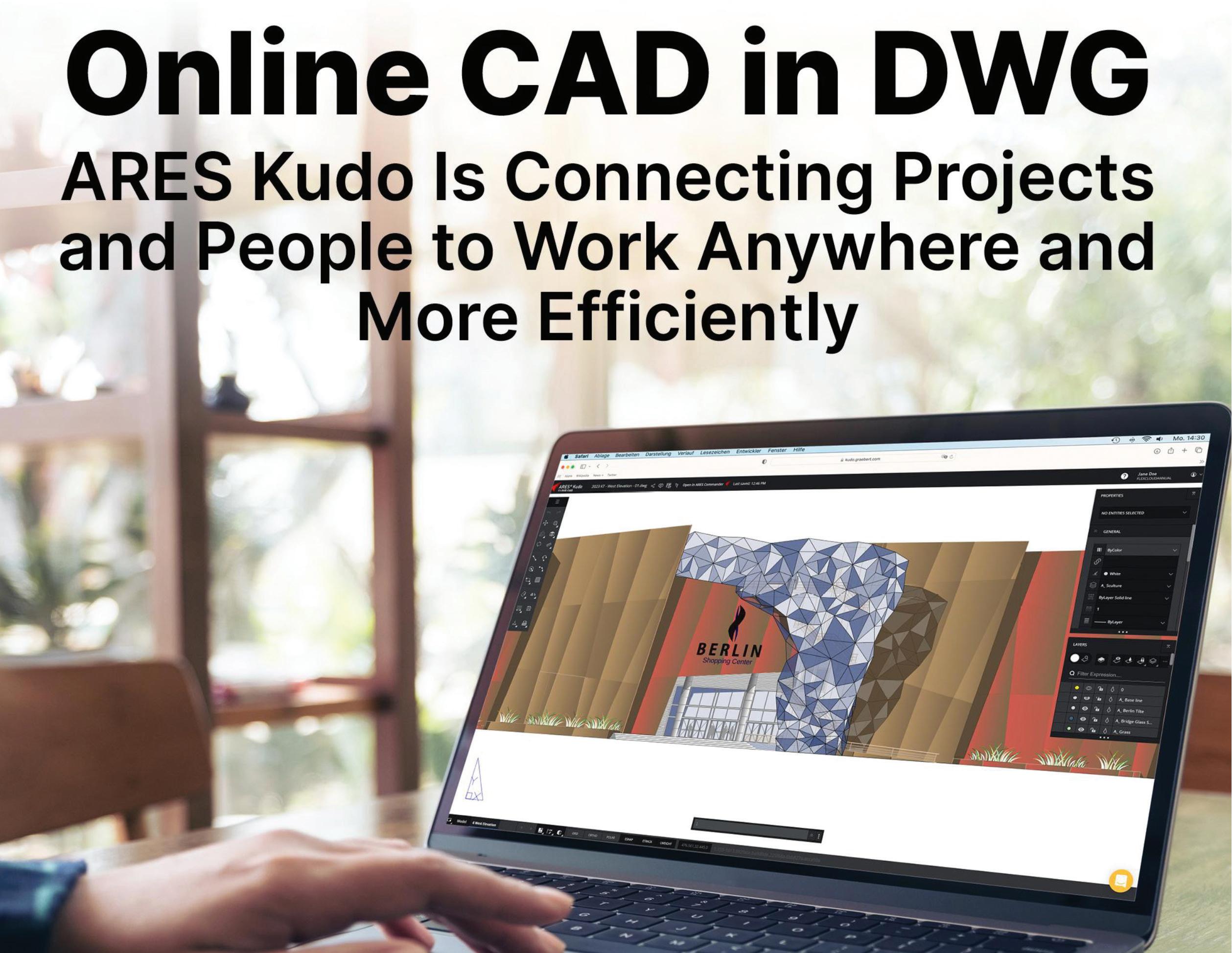
What is the cloud really improving?
Traditional desktop CAD software and its newer counterpart, cloudbased CAD, have much in common when it comes to features, capabilities, and interfaces. But online CAD has the power to resolve collaboration challenges and bring people together in ways that desktop CAD cannot.
No man is an island, and — with apologies to John Donne — no CAD user is, either. Regardless of the industry, every project involves some combination of collaborators, coworkers, and customers, both internal and external. And no matter what their roles are, all those people need to be connected to the project, and to each other, so they can propose new ideas, comment on designs, and approve changes.
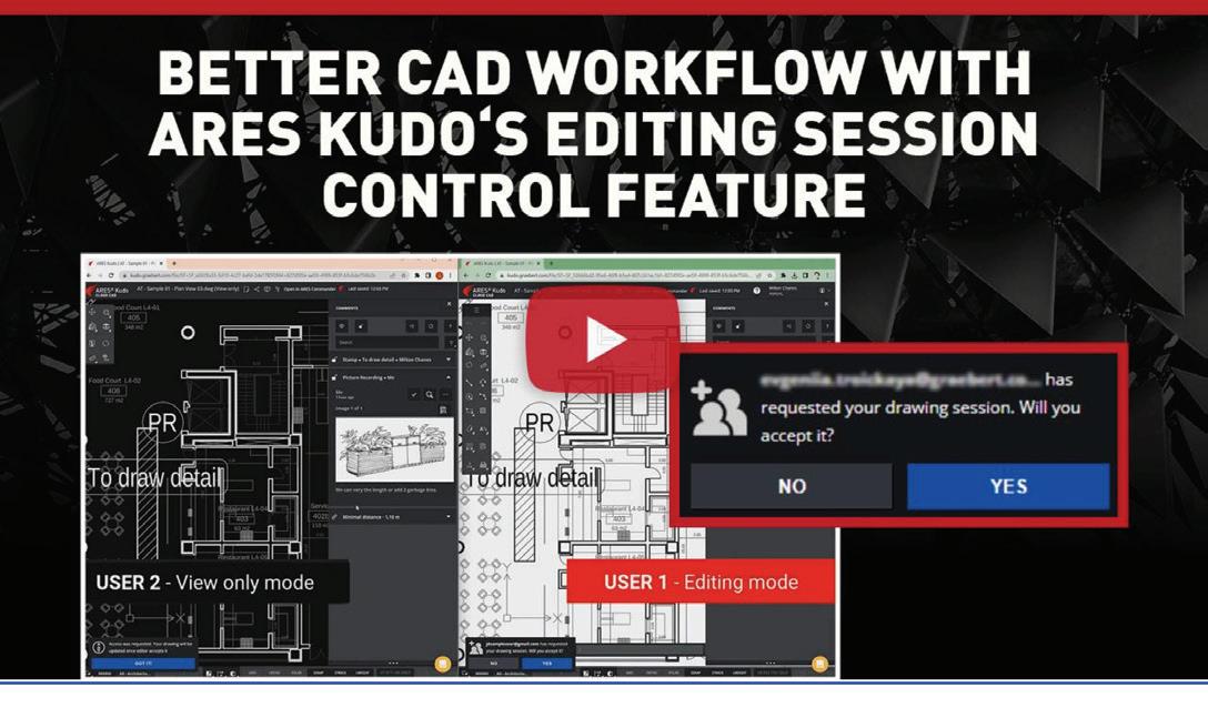
Discover in this video how ARES Kudo provides a full set of 2D CAD features for DWG.

The cost of one year of ARES Kudo is only $120 per user, or $200 per user when combined with the mobile version, ARES Touch. https://www.youtube.com/watch?v=E7HfqNthhOQ&list=PLStPIOs Wm9vFjJdp1ulh2Aeqx3NfxR8tS&index=3
AUGIWORLD Magazine | October 2023 augi.com 20 ARES Kudo by: Cyrena Respini-Irwin
Coordinating all this collaboration is a technical challenge — one that may be more daunting than those in your drawings. Fortunately, Graebert (www. graebert.com) offers a full-featured, cloud-based CAD program that addresses both at once: ARES Kudo provides the tools to create and modify DWG drawings and solve the collaboration problems that come along with every project. It runs in an Internet browser, so there’s nothing to install, and connects with a variety of cloud storage providers, and you’re free to choose where to store your files.
ARES KUDO ONLINE CAD: KEY BENEFITS
ARES Kudo is both a stand-alone product, and the hub of the ARES Trinity of CAD Software, where it is joined by ARES Commander (for Windows, MacOS, and Linux) and ARES Touch (for iOS and Android). It powers the Trinity collaboration features; for example, because it is a cloud-based solution, ARES Kudo can synchronize files across all users and all types of devices. That means a user can start a project on a desktop computer in the office, then return to it on a laptop at home, or hand it off to a colleague working on a borrowed machine at a client site. In other words, your DWG files follow you wherever you go, so you and your team can view, create, and modify them anywhere.
That synchronization is just one of the ways that ARES Kudo can foster more effective collaboration and ultimately, an improved project experience for everyone involved. Here, we’ll look at how it can overcome collaboration challenges to better connect your team, resulting in faster workflows and fewer frustrations.
Challenge No. 1: Providing Secure Remote Access to Drawings
Nowadays, users are often working remotely, which means they could be in home offices, on the go, or in just about any location that’s removed from their teammates. Many teams even include members working from different countries. For IT departments, this poses a challenge: How to enable users to work from all these locations without compromising on security or performance?
Virtualization and VPNs are sometimes employed, enabling the user to connect to a virtual desk. These technologies work by streaming a virtual environment to any remote device. While these techniques meet expectations in terms of security, they are expensive, and they frequently require
compromising on performance.
Fully cloud-based solutions, like ARES Kudo, are much easier to deploy. The user only needs an Internet browser and can work instantly on any device — without any assistance from the IT department.
ARES Kudo also significantly improves security. Instead of circulating files by email or on USB drives (which implies that files are duplicated, and potentially shared with unauthorized people), users are invited to centralize all the projects in a cloud storage chosen and controlled by their company.
Each user is authenticated by a login and password, and on top of that, each user can only access the drawings that he or she has been granted permissions to. Access can be granted or revoked at any time, and you can also decide who can modify the drawing — and who can only view it. Likewise, you can control who is allowed to share the files with other users, and at any time, check who has permissions on your files.
Challenge No. 2: Coordinating Dispersed Contributors
In the past, project stakeholders might have gathered in a conference room for a face-to-face discussion (provided they could agree on a time to meet). Now, it’s more likely that the group is scattered far and wide, with team members weighing in from home offices, remote branches, and job sites.
These locations often span multiple countries and time zones, making asynchronous work — and communication — a necessity. Because ARES Kudo files are stored in the cloud, they’re available around the clock to everyone on the team, whether they’re in Seattle or Singapore.
And since everyone always sees the same file version, and it’s always current, there’s no risk of the confusion and chaos that can result when multiple versions are in circulation.
Challenge No. 3: Increasing Inclusion without Increasing Costs
It isn’t just far-flung users who benefit from the feedback functions in ARES Kudo; those in neighboring cubicles can take advantage too, even if your company budget is tight. After their
augi.com/augiworld October 2023 | AUGIWORLD Magazine 21 ARES Kudo
ARES Kudo
30-day trial has ended, users who don’t purchase a license will lose access to the CAD features of ARES Kudo, but they can continue to use the viewing, commenting, and markup functions for free.
Consequently, IT departments can reduce software spending by purchasing licenses only for their ARES Kudo users who create drawings, while those who only comment on or validate designs can use the limited, free version. That means anyone in the company, from sales to marketing to management, can easily be included in reviewing projects — without increasing costs.
Challenge No. 4: Collecting Feedback from Customers or Colleagues
With the view-only link feature, ARES Kudo users can share drawings with anyone, inside or outside their organization. The link provides access to the drawing itself — not a snapshot or static PDF — so it is always up to date.

The recipient of a view-only link doesn’t need to purchase or download anything (since ARES Kudo runs entirely in an Internet browser), and using the link is free. This makes it supremely simple to share drawings with managers for review or with clients for approval, among others. And the Kudo user who created the link retains control over the security features: they can add a password or expiration date if desired, or even deactivate the link at any time.
The program offers multiple formats for feedback, including text comments, picture and voice recordings, and stamps, all of which are simple and intuitive. (Note that none of these tools modify the drawing; comments and markups reside on a separate layer. There is no way for a user to change the drawing itself, either intentionally or accidentally, unless they have been assigned an Editor role by the drawing owner).
Challenge No. 5: Keeping Everyone Current
Whether or not everyone on the team can squeeze into the same conference room, they can all keep up with project developments on their own schedule, thanks to email notifications sent automatically whenever there is activity in the file (such a new comment). Users can control how frequently they receive these notifications, or opt out altogether.
ARES Kudo also includes other features to help users understand the modifications made by others.
To begin with, the Version History feature keeps track of the successive changes from each user. If desired, you can revert changes to turn back the clock and return to a previous version of the drawing. Comments and markups enable users to discuss and explain the changes with text, images, or voice recordings.
And if you need help to understand the differences between two drawings, the Drawing Compare feature makes the process quick and easy:
https://www.youtube.com/watch?v=qsdtf6moFh0&list=PLStPIOs Wm9vFjJdp1ulh2Aeqx3NfxR8tS&index=7
The easy-to-use commenting and markup tools in ARES Kudo make it possible for all kinds of collaborators to share their feedback on a project, whether or not they have experience with CAD.

Compare two drawings online and analyze their differences with ARES Kudo.
https://www.youtube.com/watch?v=le34TE-iIYk&list=PLStPIOsW m9vFjJdp1ulh2Aeqx3NfxR8tS&index=5
AUGIWORLD Magazine | October 2023 augi.com 22
View-only links enable your contacts to view and comment for free.
Challenge No. 6: Taking the Trouble out of Taking Turns
Working apart from each other increases the likelihood that two users will step on each other’s toes by editing the same file simultaneously. You may have encountered this problem when working on a file hosted by a cloud storage provider, such as Google Drive, that doesn’t automatically prevent this kind of conflict.
ARES Kudo’s session handling system, in contrast, ensures that only one user can edit at a time, even if several people with the Editor role have the file open. In the meantime, other users are free to view the file, check the comments and markups, and add their own. If there’s an urgent need to transfer the editing session, any user with Editor status can send a real-time request to the person currently editing.
how easy it is to improve collaboration and build better connections with ARES Kudo.
https://www.youtube.com/watch?v=GgRAXZP9m-A&list=PLStPIO sWm9vFjJdp1ulh2Aeqx3NfxR8tS&index=6
And you never have to worry that progress will come to a halt when Naptime Neil dozes off at his desk with an important file still open, or Forgetful Francine leaves for vacation without closing the project on her workstation. After 25 minutes of inactivity, an editing session will automatically change to view-only mode, freeing up the file for the next user who’s eager to edit.
CONQUER YOUR COLLABORATION CHALLENGES WITH ARES KUDO
Although the collaboration features are modern, the interface and commands in ARES Kudo will feel comfortably familiar to anyone who has used CAD tools such as ARES Commander or AutoCAD. Sign up for your 30-day free trial, and see for yourself

If some of your colleagues are reluctant to change their habits (or simply prefer to move to modern collaboration frameworks at their own pace), they can try ARES Commander instead. ARES Commander is Graebert’s flagship product for Windows, Mac, and Linux computers. Compared to ARES Kudo, it includes more advanced features, but also an AutoCAD-like user interface. And thanks to Graebert’s Trinity concept, ARES Commander users can benefit from the same collaboration features offered in ARES Kudo. A key advantage of ARES Commander, therefore, is to offer a hybrid approach: Depending on the needs of each project, you may choose to work with local files saved on your hard disk, or with files synchronized with other users by leveraging the Trinity collaboration features.
To learn more, please visit the Graebert site or our Youtube channel.
Cyrena Respini-Irwin covered CAD and related technologies for more than a decade at Cadalyst, where she became Editor in Chief. In 2021 she joined Graebert as the Brand Ambassador for the ARES Trinity of CAD software.

augi.com/augiworld October 2023 | AUGIWORLD Magazine 23 ARES Kudo
Two CAD users working in parallel on the same file with ARES Kudo.
I am Tired of This (Part of the Secrets Tech Managers Keep)
The next secret that Tech Managers keep is that they are tired of putting up with some things. Some are frustrated with the things that others may not know anything about. Some are nearing a breaking point. Some may be thinking that it will never get better. Let’s look at the things that are making them tired and what can be done about it.

TOO MUCH WORK, NOT ENOUGH TIME
There is always a long list of things that need to be done. There are endless projects to be completed, research to investigate and housekeeping tasks. But sometimes it gets overwhelming. People keep coming to you and asking for help. They need to be served and your plate is full. The backlog keeps growing and you are not making headway. It is frustrating and it looks like there is no relief coming. And if you have no one else to help, it all lands in your lap. But, if the company does not want to provide additional staff and you have asked for it (see prior
article on staffing), then you are left with your own two hands and that is it. You go home tired and feeling like you didn’t satisfy anyone or complete anything.
What to do about it - Realize that you are one person. When the task list gets too long, start explaining it to others. “I can take this on, but other things might be delayed” or “I can’t get to this today, but maybe next week. Is that okay?” Then prioritize the tasks and start getting them down, one by one. It is the most you can do, and you do not need to feel like you are failing. You can go home at the end of the day (and not stay all night) with a feeling of accomplishment for those items you got done.
NOT ENOUGH COMPLIANCE
You make guidelines, standards and protocols that assist with streamlining, structuring, and increasing productivity. You put in hours of process analysis, observation, and discussion to come up with
AUGIWORLD Magazine | October 2023 augi.com 24 by:
Kiker Tech Manager
Mark
procedures that help everyone work more efficiently. Then no one follows them. They say they do, but they don’t. Or maybe they just forget. Or they must move faster to meet project deadlines and do things on the fly. Whatever the reason… things are not standardized, and rules are not followed.
What to do about it – Realize that most folks do not have the same level of concern about standards and guidelines. They just want to do their jobs and get the projects out the door. And they sometimes don’t even admit that they have violated the rules. So, you need to gauge the severity of the violation and put it into perspective. If it is egregious and will break other things down the road, then it needs to be addressed. If it is slight and really does not impact the project, then you might want to remind them of the guidelines and let it slide. Pick your battles, pick the ones you can win, and stick to your guns. You may have to just fix things yourself. But if it is a deviation that could be passed onto other projects, take care of it. Don’t let the mess get messier.
YOU INHERITED CHAOS
When you stepped into the role of Tech Manager, you either filled another person’s spot or were the first person to fill that wrung on the ladder. The position may have been created for you or by you and now you must make it better. You may have been promoted into the role as others left the firm or moved to other positions. Either way, you probably are tired of the mess that the systems and guidelines may be in. You are tired of things not being properly structured. You are tired of the guidelines being silent about new areas of design or tools that you have begun using.
What to do about it – Don’t keep telling people that you inherited this mess. That only works for a few months and then folks will expect you to do something about it. So, get to it. Start with some easy wins, like adding guidelines for some new tools or features that your team has embraced. Or maybe some easier housecleaning of old projects. Start developing a circle of informants that can help you flag the anomalies that need to be fixed. Prioritize them and start banging away on making things better.
REPETITIVE WORK
You are tired of doing the same thing. Day after day, week after week, months on end. The tedium of some of the tasks you have to do is deflating. You
are asked to do the same things or fix the same problems again and again. You must redo the work of others that was not done right. You have to correct repeated mistakes that others make. You have to train newcomers in the same processes that you trained others in. It just seems so repetitive.
What to do about it – Understand that every job has its repetitive parts. Things are like this for everyone. Flight attendants repeat the same safety procedure before every take off. Tire techs change tires multiple times a day using the same process every time. Coffee houses brew millions of cups of coffee the same way. Everything is repetitive. But in between the repeat performances of your tasks, you get new projects, new tech, new hardware, and software to research, review, select and deploy. Tech workers actually live in a constant state of change. So, knuckle down during the monotonous parts and work to get them more productive and done in short amounts of time so you can move on to the new and shiny parts of your job.
These things and more can make you tired. You can be worn down by the parade of projects, no one following the rules, the chaos, and the recurring nature of the work. But you can get through it. You won’t always be tired. Relief will come. You will get a break. Hang in there until it comes.
Mark Kiker has more than 30 years of hands-on experience with technology. He is fully versed in every area of management from deployment planning, installation, and configuration to training and strategic planning. He is an internationally known speaker, writer and former AUGI Board member and president. Mark is currently serving as Chief Technology Officer for SIATech, a non-profit public charter high school focused on dropout recovery. He oversees two web sites, www.caddmanager.com and www.bimmanager.com. He can be reached at mark. kiker@augi.com and would love to hear your questions, comments and perspectives.

augi.com/augiworld October 2023 | AUGIWORLD Magazine 25 Tech Manager
Reflections on a Decade of Training and Education in AECO

AUGIWORLD Magazine | October 2023 augi.com 26 by: William Myers Training
Where does the time go, and how things have changed!
These thoughts can be found dancing around the front of my mind, as I consider writing a new article for AUGIWORLD. At the same time, I am attending a virtual BIM Coordinators Summit event in the UK - from the comfort of my home. At this event, massive consideration is being given to BIM skills training and certification. This being the third article that I have had the privilege of submitting for the Training and Education issue for this publication, I find myself reflecting on what’s changed and what has stayed constant.
The first article I wrote was a full decade ago, with the second a short three years after that. Time has flown, and many things have certainly changed in this ecosystem of industries that Autodesk supports. Back then, the online training and education industry was in its gestation. I still recall being told by educational experts that we could never effectively teach AutoCAD or other Autodesk software online or in an asynchronous setting. Obviously that idea is now a notion of the past.
Now the industry and userbase are quite mature. Prospective partners know what they want - and what they don’t. Going beyond educating people about the fundamentals of effective online training, we are now working with our partners to develop their own training, on their own platforms, based on their unique requirements - with user data and customer feedback to tailor specific technical or personnel-based customizations.
My first article also coincided with the first time I attended Autodesk University. At that time, the emergence of cloud storage and the promise of cloud computing were big features for the week. There were presentations about the future of construction, featuring Augmented and Virtual Reality simulations, and automated bots which could perform unsafe or repetitive tasks.
We were talking about the promise of Artificial Intelligence, as described by our favorite Sci-Fi movies.
All these wild and future looking ideas are now reality and are increasingly prevalent in the several industries which the world of design touches.
My first AU coincided with my first experience with the Autodesk Certified Instructor (ACI) program. As an Autodesk Certified Professional in AutoCAD, Revit, and Inventor, I had been invited to observe the ACI training program, to determine its value to our Authorized Autodesk Training Center (ATC), in Edmonton, Canada.
That foundational experience was incredibly eyeopening and impactful. I recognized the value of the ACI program immediately, and after a few years the instructors in our ATC were all certified.
The ACI program has grown and changed with time as well. But it still communicates the essence of what is important about effective training, instructional design, and the concept of knowledge transfer in general.
DON’T TALK ABOUT IT, BE ABOUT IT
I have always appreciated the value of Autodesk Certification, starting with the Certified User and Professional exams. I appreciate what successful completion and certification shows on a resume. It symbolizes more than an understanding of software. Beyond that, it demonstrates a commitment to lifelong learning and a love of achievement. It shows dedication and commitment to a goal.
Getting certified in Autodesk software enabled me to transition from working in coveralls to working, well, without the need for them. It proves that, to some extent, I have conversational and practical knowledge of these software platforms. It may not prove that I am a power user - which I am not- but it gives me the confidence to speak with power users in a way that demonstrates some level of professional credibility.
augi.com/augiworld October 2023 | AUGIWORLD Magazine 27 Training
I APPRECIATE WHAT SUCCESSFUL COMPLETION AND CERTIFICATION SHOWS ON A RESUME. IT SYMBOLIZES MORE THAN AN UNDERSTANDING OF SOFTWARE.
ON AUTODESK CERTIFICATION BEING THE GOLD STANDARD

Looking back at that first ACI event and taking it a step further, my appreciation for the process of becoming ACI Certified has only grown. It’s been a decade since I first became aware of the initiative, and I’m now working towards Platinum status.
Similar to the way that the Autodesk software certification demonstrates proof of ones understanding of the foundational capabilities of the software, the ACI certification demonstrates proof of the understanding of the foundational elements of proper and effective knowledge transfer.
In my career in training and education of about 15 years, ACI certification has provided me with a guide and best practices for the proper planning and delivery of training, knowledge transfer, onboarding, etc.
I see so much benefit for BIM/CAD Managers, Training Managers, Knowledge Management Directors, etc., in having certification. It is still a shock to me when chatting with someone in one of those roles, finding out that they had arrived there. Often, it was not because they came from an educational or instructional deign background. Rather, it was because they knew the most about a certain software, had organization-specific knowledge and experience, or had simply shown some level of knowledge-based leadership in the past.
Certainly not everyone in these roles can be, or needs to be, ACI certified. However, the foundational elements of that training and certification could- and should- be the standards by which all knowledge transfer is conducted, whether it be in the boardroom, the lunchroom, the classroom, or increasingly, the dining room or bedroom office.
Looking back at how things have changed in the ecosystems that Autodesk supports, and how the software itself has evolved with it, I find it notable that the principles of effective training have not changed much- if at all.
START AT THE BEGINNING, BY DESCRIBING THE DESTINATION
As a method for planning a training session, the best place to start is with a description of what the trainee will have learned by the end of the session. Defining learning objectives and learning outcomes creates an immediate outline for the session, and a way to measure the success of the session- for both learner and learning provider.
The best training is always modelled after a learning cycle of Lecture > Demonstration> Activity > Assessment.

The Lecture section doesn’t not have to be a lecture. When done well, a lecture portion in the learning cycle introduces the subject. It provides a frame of reference for its uses and intended effects. In the lecture portion, the learning provider and the learner discover the concept- whatever it is. ‘We’ is used in this section as a result.
In the Demonstration portion, the learning provider (I) shows the learner how to complete tasks related to the concept. This moves into the Activity portion,
AUGIWORLD Magazine | October 2023 augi.com 28 Training
Learning Cycle
where the learner (you) works through examples of the tasks related to the concept.
Finally, the Assessment portion gives the learning provider an opportunity to gauge the success of their training and the success of their training plan. While traditional testing will always have its place, my favorite time to conduct that assessment phase is during the activity section. Here, I can interact with the learner and gauge their proficiency in a more conversational manner. Further, I can use this time and those assessments to support any slower learners and challenge the faster learners with advanced concepts.
It’s just a few simple concepts, but these concepts are at the core of the ACI certification.
ACI certification verifies that those concepts can be applied in the transfer of Autodesk software skills and workflow knowledge. Considering these concepts, even as part of a simple training plan–something which most people find themselves eventually having to create- will nearly guarantee the success of the actual learning session.
As the rate of our technological advancement increases, the pace at which we are required to learn– and to transfer knowledge- increases along with it. My firm belief is that ACI Certification imparts an understanding of the simplest- yet most effective- means by which knowledge is transferred for Autodesk design products. Being able to transfer those foundational concepts into any training situation is truly an added value.
In that, it’s comforting to know that as quickly as things change, we can still apply the classical hallmarks of effective training to keep on the ballstay ahead of the game.

Learning Styles
The most effective training will also consider different learning styles- and the different combination of learning styles among the learnersto be equally important to the learning cycle. I think the simplest method for categorizing these learning styles is still with the acronym V.A.R.K.

• Visual
• Audio
• Read / Write
• Kinesthetic
To ensure that all these learning styles are supported in a learning session, is to ensure the measurable success of your training- and training plan- in each learning cycle.
William Myers is Director of Operations with Global eTraining (GeT), an awardwinning leader in online Technical Skills training. He is their longest standing employee and was recognized as ‘Employee of the Year - 2016’ by GeT’s mother company, Brattberg EdVentures. Will is a Gold Status Autodesk Certified Instructor, for AutoCAD, Revit Architecture, and Inventor, holding multiple years’ worth of Autodesk Professional Certifications for all three platforms. He has spoken about BIM at Autodesk University, as well as various Canadian BIM events. He has previously contributed to the AUGIWORLD“Training & Education” issue in 2012 and 2016. Will recently completed a hike of Canada’s West Coast Trail, enjoys cooking, jogging/ hiking, and is an obsessive vinyl record collector.
augi.com/augiworld October 2023 | AUGIWORLD Magazine 29
Training
BricsCAD Customizations

Did you recently purchase a vehicle? I am going to take a guess and say you adjusted your mirrors, and the seat, programmed a radio station, or set up Bluetooth. What about your cell phone? I am going to take another guess and say you changed the background and added a few apps. What about the sandwich you had for lunch? I might take some heat for this, but I cannot have pickles on my sandwich. Trust me, I’ve heard your propickle perspective and while I respect it, it’s not for me. That said, aren’t we all appreciative of customizations?
Customizing is personalizing it, making it yours, allowing you to feel comfortable, and actually enjoying the sandwich with or without the pickle. The same theory can be applied to your BricsCAD environment.
WHY WOULD I CUSTOMIZE?
Here are the top reasons to customize your BricsCAD environment and what you might consider customizing:
1. Increased Productivity: Customizing BricsCAD allows you to tailor the software to your specific needs, making common tasks quicker and more efficient. You can create custom tool palettes, menus, and shortcuts for frequently used commands, reducing the time spent searching for commands in menus.
2. Consistency and Standardization: Customization ensures that your team or organization follows a consistent set of drafting and design standards. You can create custom templates, styles, and blocks, ensuring that everyone uses the same standards, which is crucial for collaboration and maintaining a professional appearance in your drawings.
3. Workflow Optimization: Customize BricsCAD to match your unique workflow. For example, if you frequently work with specific types of drawings or projects, you can set up customized drawing templates with predefined layers, text styles, and dimension styles to save time on setup and reduce errors.
4. Personalization: Make BricsCAD your own by customizing the user interface to fit your
AUGIWORLD Magazine | October 2023 augi.com 30 BricsCAD
by: Craig Swearingen
preferences. You can rearrange toolbars, change the color scheme, and adjust the workspace layout to create a more comfortable and visually appealing environment. (See Figure 1)
WHAT TO CUSTOMIZE IN BRICSCAD:
• BricsCAD QUAD Cursor Menu: Adjust the BricsCAD QUAD cursor to benefit the commands you use most frequently. With QUAD, it’s simple and easy to execute complex commands that normally require several clicks, options, and dialog boxes. This can significantly speed up your drafting and design work.
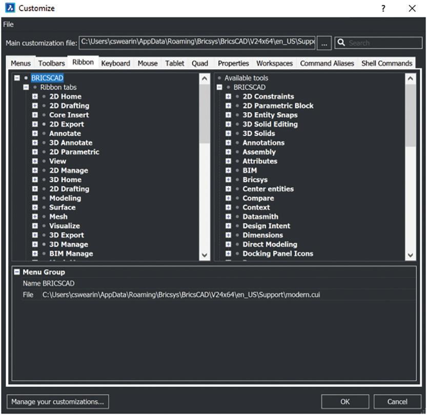
• Custom Menus and Toolbars: Create custom menus and toolbars with your most frequently used commands. This can be especially helpful if you have specialized workflows or use certain commands more often than others.
• Keyboard Shortcuts: Assign keyboard shortcuts to frequently used commands. This can significantly speed up your drafting and design work, as you won’t need to navigate through menus.
• Custom Linetypes and Hatch Patterns: If your work involves specific linetypes or hatch patterns that aren’t included by default, you can create custom linetypes and hatch patterns.
• Custom Templates: Develop custom drawing templates with predefined layers, text styles, dimension styles, and title blocks. This ensures that each new drawing you create adheres to your organization’s standards.
• Custom Scripts and Macros: Learn how to write scripts or use the built-in Visual LISP functionality to automate tasks or create custom commands tailored to your workflow. BLADE is the BricsCAD LISP Advanced Development Environment. It’s a feature in BricsCAD that allows users to interactively edit and debug LISP applications. It opens in an external application window, allowing it to remain open while you work on your drawings in BricsCAD.
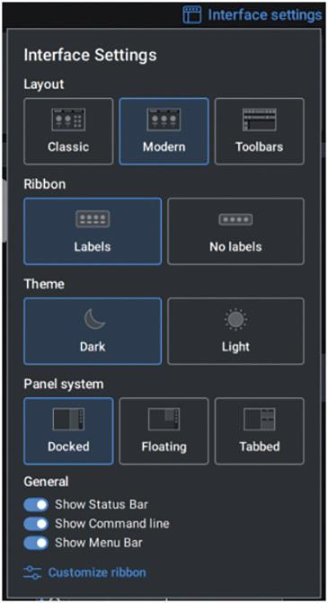
• Workspace Configuration: Adjust the BricsCAD User Interface and workspace layout to better suit your preferences. You can customize the arrangement of palettes, toolbars, and panels
augi.com/augiworld October 2023 | AUGIWORLD Magazine 31 BricsCAD
Figure 1
to make them easily accessible. BricsCAD has created an interface settings that allows you to manage the interface display of your BricsCAD workspace. (See Figure 2)
• Custom Plot Styles: Create custom plot styles (CTB or STB files) to control how your drawings are plotted or printed, ensuring consistent output.
• Block Libraries: Build libraries of frequently used blocks or symbols, making it easy to insert common elements into your drawings from the Library Panel.
• Custom Tool Palettes: Develop custom tool palettes with commands, text, dimension styles, hatch patterns, and blocks. This ensures that consistency across your organization’s standards in addition provide custom configurations when you work with different users or departments.
ADDITIONAL THOUGHTS
Remember that customization should strike a balance between optimizing your workflow and not making it overly complex. Ideally, users should
have the tools at their disposal to do their job. Beyond that, each user has their personal preference on how their UI appears, where things are placed, and how they want things to look. Just like the background on your cell phone or pickles on your sandwich, what’s good for you may not be good for me.
Fortunately, with BricsCAD, you can have it your way, just the way you like it.

MORE ABOUT BRICSCAD®
Bricsys® BricsCAD® is cost-effective professional CAD software without compromise. Accelerate your time to deliverable without compromising on performance, cost, licensing flexibility, and data security. Not ready to buy? Download the free, 30-day trial of BricsCAD® at Bricsys.com. Would you like free lessons? We have that available with Bricsys Learning. Ready to migrate to BricsCAD®? Download the Migration Guide. The latest version of BricsCAD® improves the tools and features users love, as well as new functionality and UI that supercharge productivity. Follow us today on LinkedIn or Youtube.
Mr. Craig Swearingen is a Global Implementation Specialist and Consultant at Bricsys®. Currently, Craig provides migration and implementation guidance, management strategies, and technical assistance to companies which need an alternative, compatible CAD solution. Craig spent 19 years in the civil engineering world as a technician, Civil 3D & CAD power user, becoming a support-intensive CAD/ IT manager in high-volume production environments. Craig is a longtime AUGI member (2009), a Certified Autodesk® AutoCAD® Professional, and he enjoys networking with other CAD users on social media.

AUGIWORLD Magazine | October 2023 augi.com 32 BricsCAD
Figure 2
Basic members have access to:
• Forums
• HotNews (last 12 months)
• AUGIWORLD (last 12 months)
DUES: Free
AUGI Members Reach Higher with Expanded Benefits

AUGI is introducing three new Membership levels that will bring you more benefits than ever before. Each level will bring you more content and expertise to share with fellow members, plus provide an expanded, more interactive website, publication access, and much more!
Are
Student members have access to:
• Forums
• HotNews (last 24 months)
• AUGIWORLD (last 24 months)
• AUGI Educational Offerings
DUES: $2/month or $20/year
Professional members have access to:
• Forums
• HotNews (full access)
• AUGIWORLD (full access and in print)
• AUGI Library
• ADN Standard Membership Offer
DUES: $5/month or $50/year
www.augi.com
you ready to upgrade yourself and your membership? Access additional benefits and upgrade at
Free Samples–The Halloween Edition

TRICK OR TREAT
When I immigrated as a nine-yearold kid to the United States, I was introduced to an event which I’ve never experienced before. As the sun was about to set on October 31st, kids from various neighborhoods would dress up, wear funny costumes, stroll from house to house carrying a small bucket, and ring strangers’ doorbells. Surprisingly, they would be greeted with smiles as screams of “Trick or Treat” rang out. Then free candies would just drop into their buckets with no questions asked. I learned very quickly that this is a very welcomed
holiday celebrated annually both in the United States and in many other countries as well. Looks like kids just like adults love getting free stuff.
FREE STUFF
As I mentioned in my February article on “Free Samples”, AutoCAD since version 2.6 has always been packaged with “free stuff.” Again, what I’m referring to are all the open source lisp files that come with AutoCAD. Since I discussed only four of these last time barely scratching the tip of the iceberg, it’s a no brainer to do follow-up articles exploring more freebies.
AUGIWORLD Magazine | October 2023 augi.com 34 by: Paul Li LISP Commands
So, for this first follow-up article I’m adding a sub theme: “The Halloween Edition.” One reason is because the calendar is once again about to land on October 31st. Another reason is because these next four free sample lisp commands I’ll be discussing had very strange and unusual development cycles. On top of that how each product ended up was completely unexpected.

Like before, with each free sample, I’ll first discuss why Autodesk may have included the free lisp file. Then I’ll demonstrate the additional function the lisp file adds to AutoCAD. Finally, I’ll conclude with what came of the free sample function as AutoCAD continued development with newer releases.
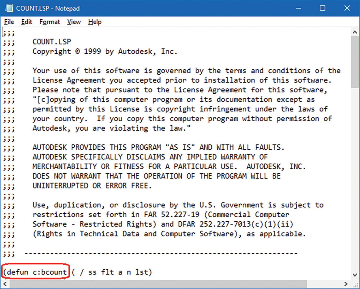
I’ve always wondered what a Count is. According to Wikipedia, this title is typically given to someone with nobility during the medieval periods in Europe. So, I’d bet that the tale of “Count Dracula” came from that part of the world as well. But returning back to the world of AutoCAD the term Count refers to getting a quantity summary. In this particular case I’m referring to the counting of Blocks. Almost a decade after AutoCAD’s initial 1982 release, there was still no command to Count all the Blocks inserted into the current drawing, add them up and return their totals in some kind of summary format. So, by May of 1990, prior to AutoCAD’s r11 release, Tony Tanzillo, one of the more advanced AutoLISP coders, took up the challenge. Tanzillo developed and then shared Count.lsp as open source code to benefit other fellow AutoCAD users (see Figure 1).
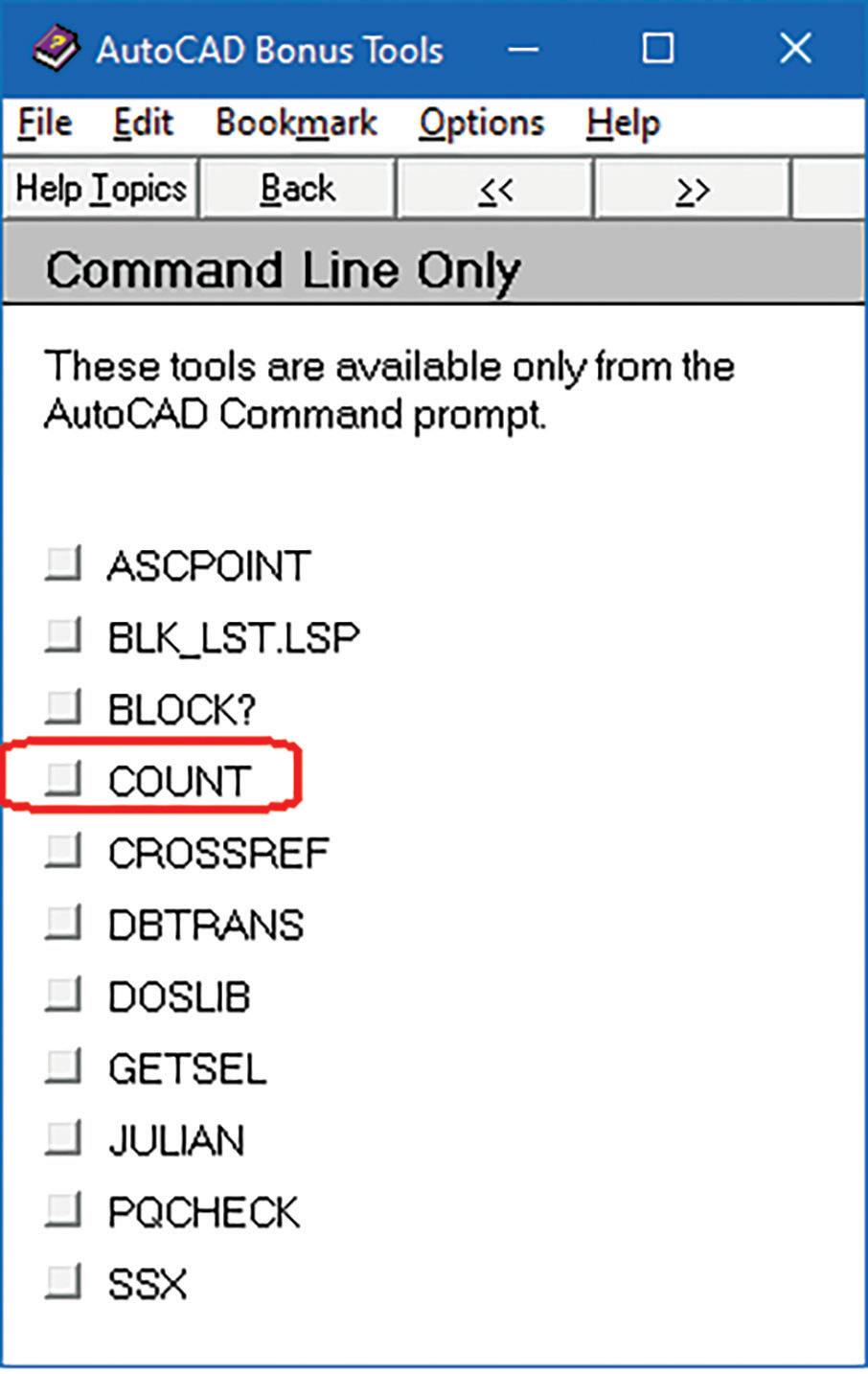
Tanzillo’s Count.lsp command became so popular throughout AutoCAD r10, r11, r12 and r13 that by 1997 when AutoCAD r14 came out, Count.lsp was now “counted” worthy to be included with the free Bonus Tools collection (see Figure 2).
Now let me demonstrate what Count.lsp actually does using AutoCAD 2021. At AutoCAD’s command prompt, the following command sequence loads the file: (load “Count”)
Note: This assumes that the lisp file is in the AutoCAD Support File Search Path; otherwise, the entire folder location would have to be included. Also, since the .lsp file extension is assumed, it does not have to be typed out.
After successfully loading the code, the command prompt shows the following:
C:COUNT loaded. Start command with COUNT.
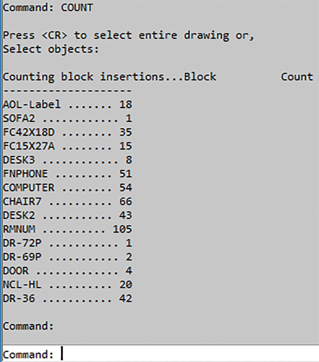
Next, type the new command COUNT. You’re then given the option to hit “Enter” to do a Count of all Blocks inserted in the entire drawing or “Select objects.” Now regardless of what objects are attempted in the selection process, only Blocks would be included. Then the Text Screen window appears over the Graphics drawing window providing a list of Blocks and their quantities found in the current drawing (see Figure 3).
augi.com/augiworld October 2023 | AUGIWORLD Magazine 35 LISP Commands
1. Count.lsp
Figure 1: Count-lsp
Figure 2: Count-r14 Bonus Tools Help
Granted, this Count command has the following limitations:
1. It does not come with a graphic user interface (GUI).
2. The header row is skewed to the right.
3. The Block names are not listed in alphabetical order.
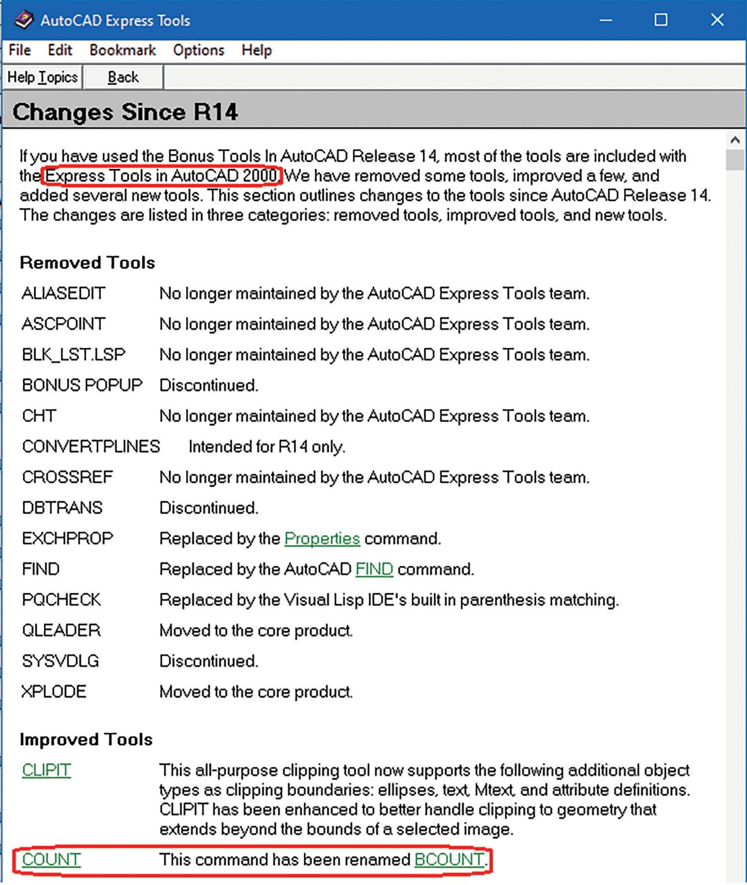
This initial attempt at getting a Block Count summary was quite impressive. But then the next developmental phase of Count.lsp took a strange twist. In March of 1999 when AutoCAD 2000 came out many of the Bonus Tools including Count.lsp were now rolled in as part of the new Express Tools package. Though on the outside the filename remained the same as Count.lsp, the code in the inside was completely rewritten with no author listed and the command name now changed to BCount (see Figure 4 and 5).
This new Count.lsp with a different internal command name of BCount kind of reminds me of another fictitious character “Dr. Jekyll and Mr. Hyde.” His exterior character may initially come off as kind and well respected but on the inside there’s a sinister character waiting for the opportunity to burst out. Here I go again with the Halloween
theme. I best get back to discussing the revised Count.lsp command.
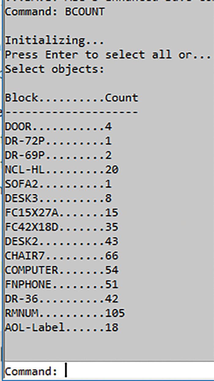
Though the code changed, there was no improvement offered. Entering BCount at the command prompt basically ends up with the same result as before. The only adjustment visible to the naked eye is with the header row now properly
AUGIWORLD Magazine | October 2023 augi.com 36 LISP Commands
Figure 3: Count-r14 Totals
Figure 4: Count-BCount-r2000 Express Tools Help
Figure 5: Count-BCount-r2000 Express Tools-lsp
positioned over each column. But the Block name listing still appears in some strange, odd order and even in a different order than before. The command also ends up leaving me at the command prompt instead of the Text Screen. I would have to manually hit the F2 or Text Screen window toggle key in order to see the complete BCount summary (see Figure 6).
Even with these shortcomings, this BCount command continued to reign supreme and
unchallenged for another 22 years until March of 2021. Finally, with the release of AutoCAD 2022 a new built-in command that’s surprisingly not called BCount, but Count was added. There’s actually a very good reason for the command name returning back to its roots. This new Count command works not only on Blocks but also on many other objectsthough there are limitations (see Figure 7).

As an alternative to starting the Count command at the command prompt, you can now right mouse click on the Graphics drawing area and Count appears as one of the commands listed on the mouse menu for selection. You can also execute Count by first selecting a supported object, then right mouse click to gain access to the Count command again listed on the mouse menu.
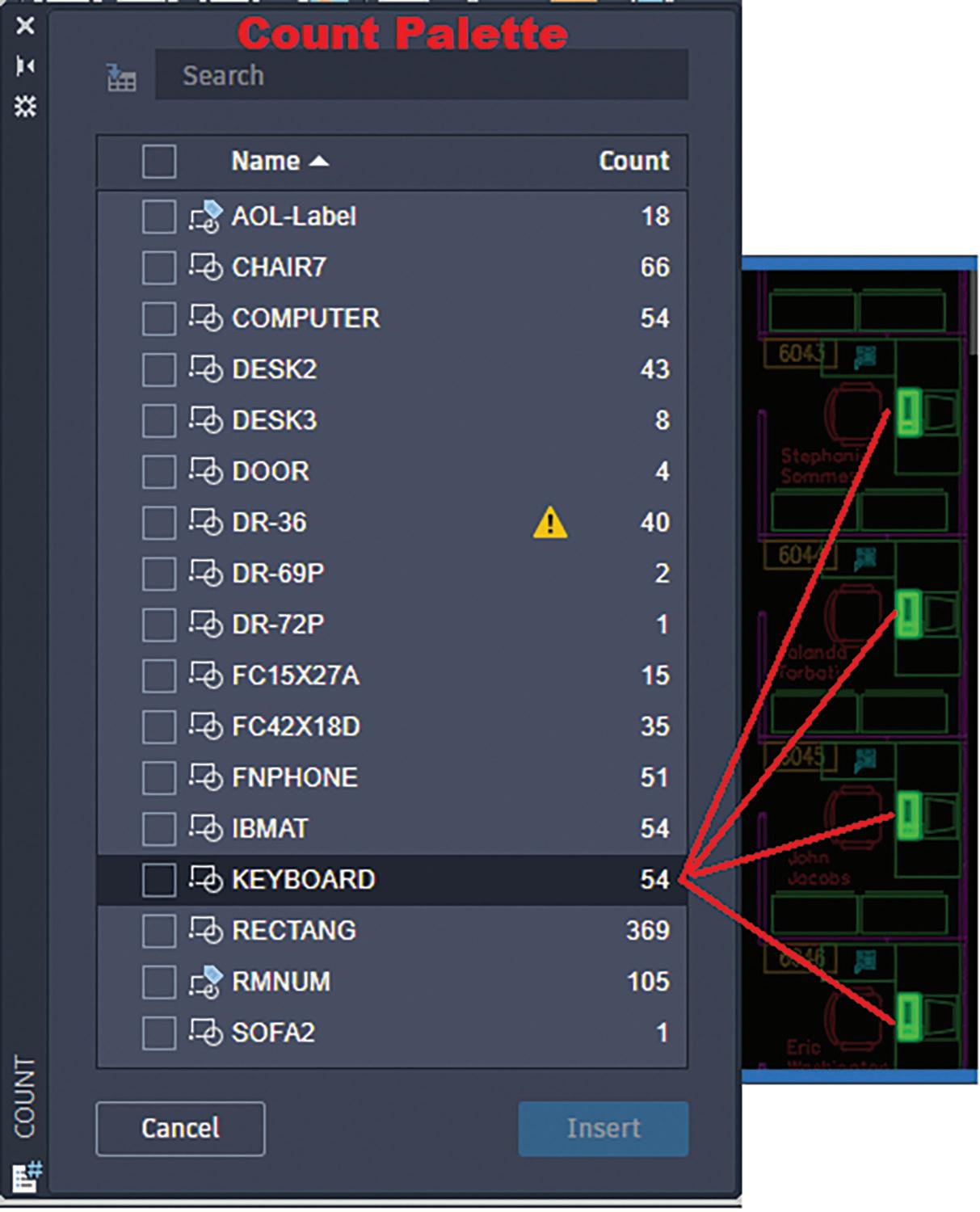
But just to compare apples to apples I will focus on Counting Blocks and not on other supported objects. Unlike the previous Count command when a drawing opens a summary of the Block Count is already created and placed in the new Count palette. The Block names are now sorted alphabetically with the option of changing the order from ascending to descending. You can
augi.com/augiworld October 2023 | AUGIWORLD Magazine 37
LISP Commands
Figure 6: Count-BCount-r2000 Totals
Figure 7: Count-r2022 Help
Figure 8: Count-r2022 Palette
also select a Block on the palette and all matching Blocks on the Graphics drawing area will be highlighted for review (see Figure 8).
Another added feature with this new and improved built-in Count command is error detection. When errors are found a yellow exclamation mark symbol appears on the palette next to the Block name. These errors now can be quickly reviewed by clicking on that error symbol. The palette would change to show what makes up the errors and the Graphic drawing area would highlight the errant Blocks (see Figure 9).

You would think that after AutoCAD 2022 introduced the new built-in Count command, Count.lsp would be dropped from future releases. But this didn’t happen. Autodesk unexpectedly decided to keep the Express Tools intact and not touch any of the added commands. So Count.lsp continues to live on as part of the Express Tools even up to the current version of AutoCAD 2024.
2. BMake.lsp
I’ve discussed so much about counting Blocks that some of you may ask: What actually is a Block? Well, Blocks have been supported since the early days of AutoCAD. Basically, a Block can be made up of various objects and typically gets placed in multiple locations in the drawing. Some simple Block examples are grid bubbles, door swings, arrow heads and etc. You can read more about Blocks in the article I recently wrote for AUGIWORLD Magazine’s June issue called Insert or Xref? That is the Question.
There’s even an option to insert the Count summary as a Table placed into the drawing. Unfortunately, there are a number of other options with the Count command that are not readily apparent. I actually prefer to see these Count options on a GUI instead of having to guess or remember what they are. So, I designed my own DDCount.lsp to show the various options for user selection (see Figure 10).
One of the advantages of using Blocks, besides getting quantity counts, is the ability to update or change them. In October of 1983, AutoCAD version 1.4 added the feature of changing or “redefining” a Block. This made it possible so that when one instance of a Block is redefined, then all copies of the same Block in the drawing automatically reflect the changes. This is a major timesaver compared to changing each Block one at a time. So how do you create a Block? This can be answered by looking at AutoCAD’s help file describing the Block command which remained about the same through AutoCAD r14 (see Figure 11).
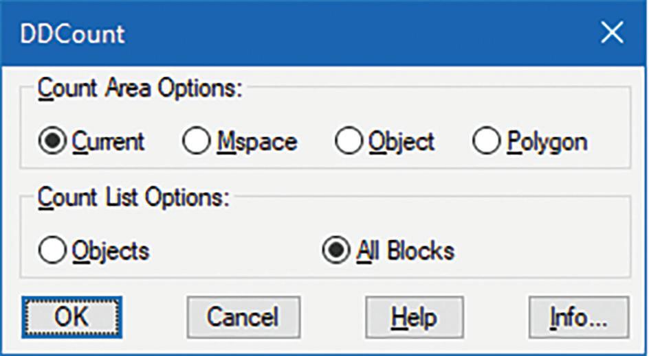
For over a decade, using a command line interface was the only method available to create a Block.
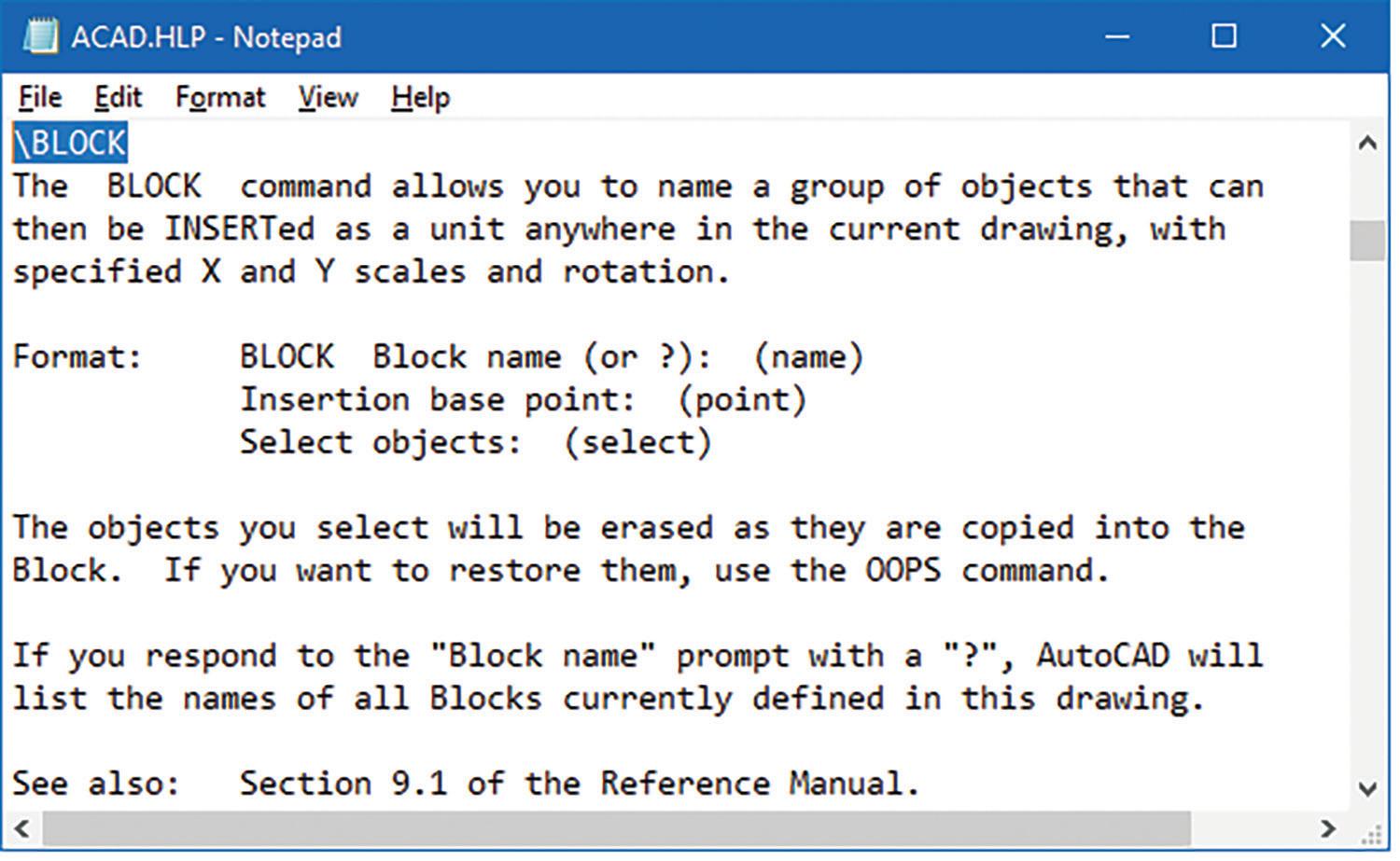
AUGIWORLD Magazine | October 2023 augi.com 38 LISP Commands
Figure 9: Count-r2022 Palette Error Report
Figure 11: r1-r14 Block Help
Figure 10: My DDCount-lsp
But this all changed in June of 1992 when AutoCAD r12 was released. AutoCAD r12 gave AutoLISP developers the new feature of creating and customizing programmable dialog boxes. This was truly a game changer. Now instead of responding to prompts one after another at the command line all the information can be collected in a single GUI before execution. This GUI was initially coded and saved in a separate file with a .DCL file extension clearly differentiating itself from the .LSP file extension where the AutoLISP code is stored. To promote this new feature AutoCAD included a number of open source DCL files with the main program as well as a separate Sample folder for customers to get a taste of this powerful addition (see Figure 12).
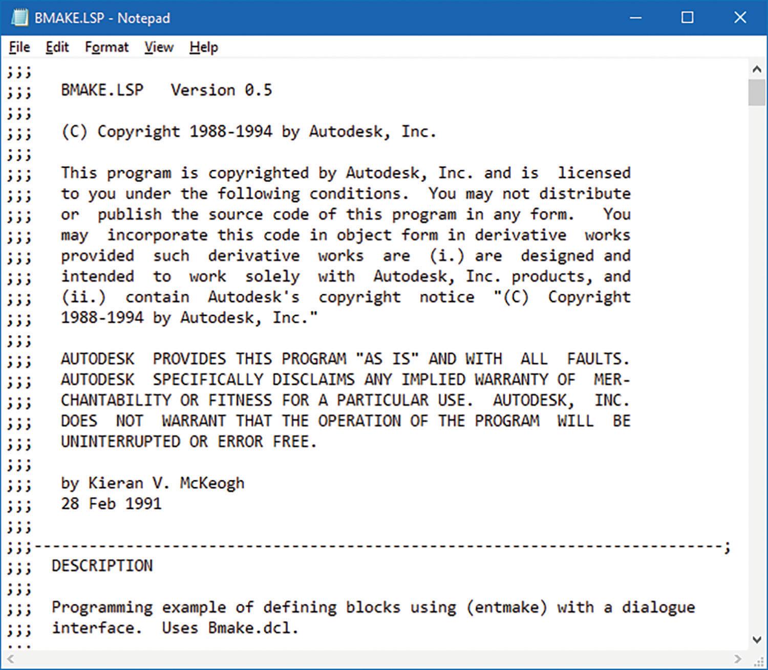
BMake.lsp and BMake.dcl, developed by Kieran V. McKeogh in February of 1991, were one of the free lisp and dcl files included with AutoCAD r12 in the Sample folder. BMake provides for the first time a GUI method to create a Block (see Figure 13 and 14).
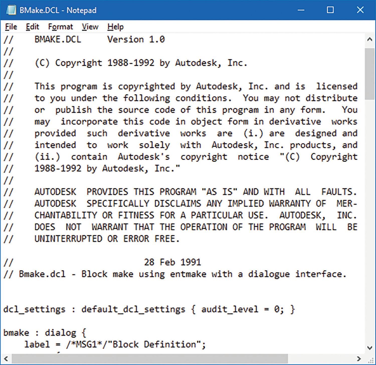
I’ve often wondered why McKeogh didn’t call the new command BBlock. After all, BBlock would make sense since it could mean a command to “be” a Block. This causes me to think of a “rom com” 2005 movie that starred Nicole Kidman called “Bewitched.” This movie actually referenced the famous mid 60’s to early 70’s TV series with the same title. In both cases it’s about a witch who met and married a mortal but now wants to try and live happily ever after without using her magic. The movie is just hilarious and of course there is one scene showing the kids knocking at the door trick or treating. I just can’t get away from this Halloween stuff.
Now in order for BMake to load properly, both BMake.lsp and BMake.dcl need to be located in one of AutoCAD’s Support File Search Paths. Then at AutoCAD’s command prompt, the following command sequence loads the file: (load “BMake”)
After successfully loading the code, the command prompt shows the following: C:BMAKE loaded. Start command with BMAKE.
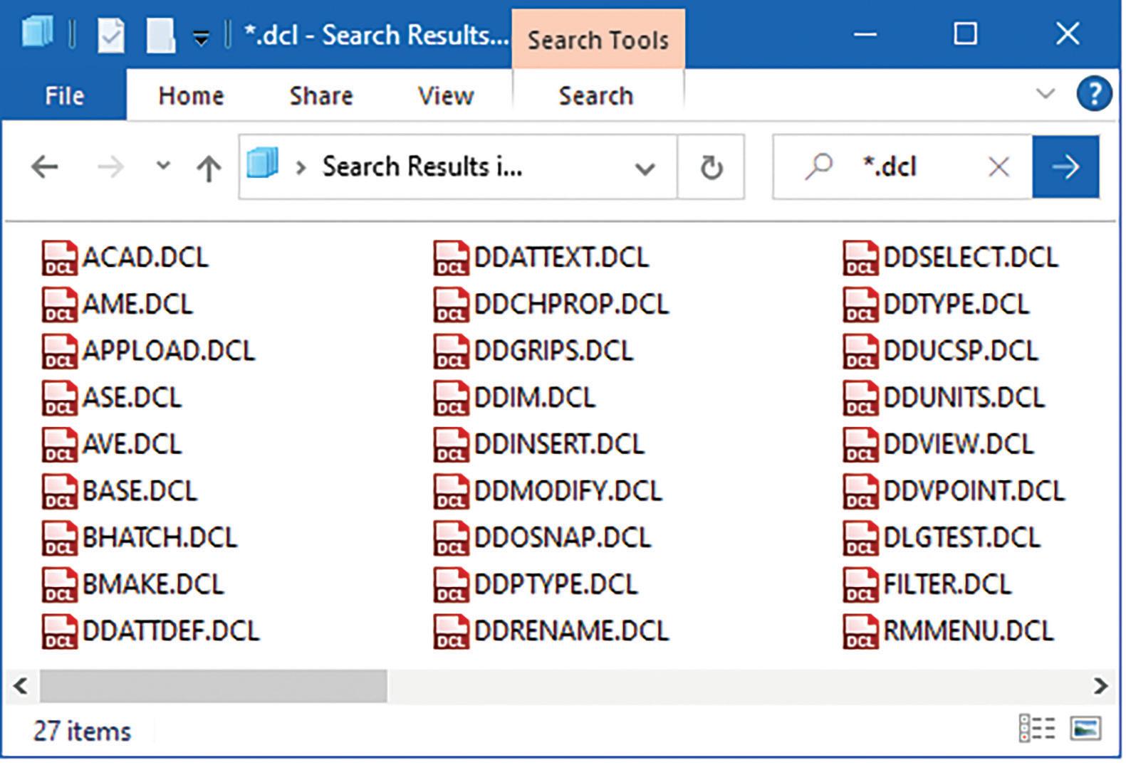
augi.com/augiworld October 2023 | AUGIWORLD Magazine 39 LISP Commands
Figure 12: r12-dcl
Figure 14: BMake-r12 Sample-dcl
Figure 13: BMake-r12 Sample-lsp
LISP Commands
Next enter the command BMake and the Block Definition GUI appears (see Figure 15).
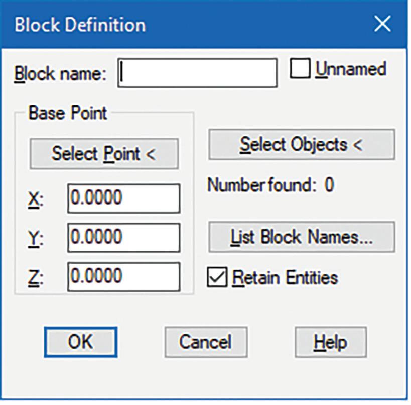
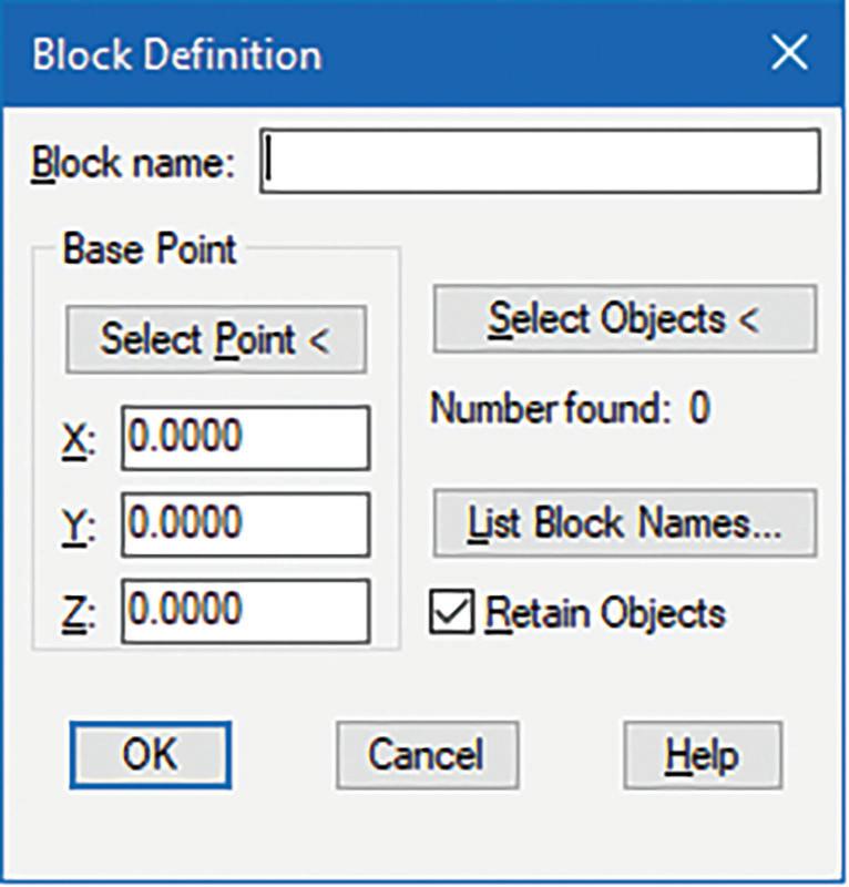
out. BMake.lsp and Bmake.dcl were shockingly resurrected from the dead. But this reappearance came with a number of changes. Now it’s no longer in the Sample folder but promoted as part of the main program in the Support folder. Like Count. lsp, BMake.lsp was completely re-written with no author listed. The version number changed from 0.5 to 14.0 matching AutoCAD’s release number. Instead of continuing on with the use of AutoLISP functions to create the Block, the code now relies entirely on the built-in Block command. Lastly, the GUI now has dropped the toggle button option of creating an “Unnamed” Block (see Figure 16 and 17).
Within the GUI all the information can be entered without the need to do it sequentially at the command prompt. After entering a Block name, you could then choose either the “Select Point” or the “Select Objects” button. The GUI would then disappear so a selection can be performed on the Graphics drawing area. Once the selection process is complete the GUI reappears for additional input. Finally, when all the needed information is filled out and the OK button is clicked then the Block is magically created.
I say magically because looking under the hood of McKeogh’s code, it does more than provide a GUI for the Block command. It goes further by creating the Block entirely from AutoLISP functions. AutoCAD’s built-in Block command is not used at all.
But then the next development phase of BMake. lsp like Count.lsp took a strange twist. When AutoCAD r13 came out in November of 1994, BMake. lsp was nowhere to be found. For some reason Autodesk chose to drop this gem completely from the AutoCAD packaging. Of course, for those die hard BMake lovers, BMake can continue to live on by copying BMake.lsp and BMake.dcl from the AutoCAD r12’s Sample folder, save them into AutoCAD r13’s Support folder and the code runs flawlessly.
Another surprising turn of events occurred again in February of 1997 when AutoCAD r14 came
Note: Unlike Count.lsp, BMake.lsp did not include a command name change. But if the command had been renamed to BBlock that would have made an even more fascinating story.
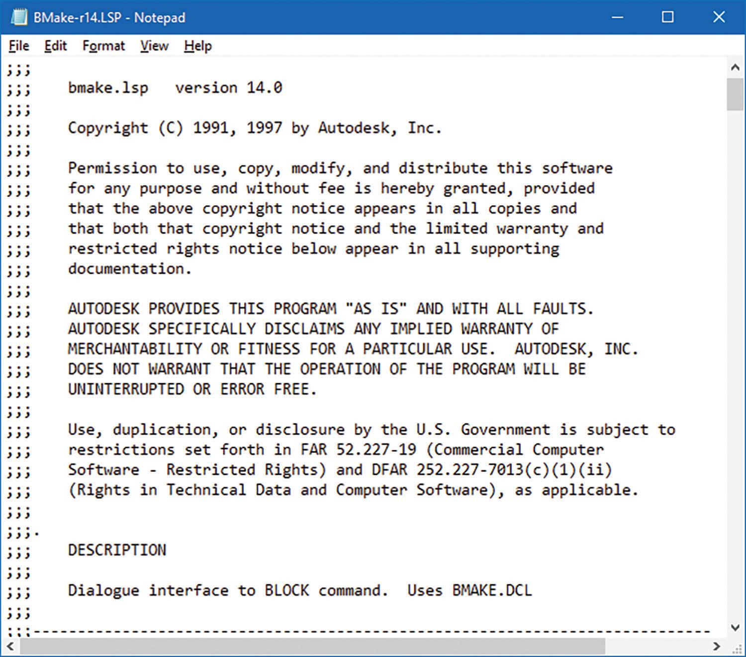
AUGIWORLD Magazine | October 2023 augi.com 40
Figure 15: BMake-r12 Sample
Figure 16: BMake-r14 Support-lsp
Figure 17: BMake-r14 Support
Then by the next release of AutoCAD in March of 1999, BMake.lsp was now gone again but this time for good. Autodesk made the decision to revamp AutoCAD’s original Block command. The redesigned Block command now presents a brandnew built-in GUI, dropping the requirement for a separate DCL file and completely replacing BMake (see Figure 18).
This initial version of the Block GUI would continue till March of 2009 when AutoCAD 2010 came out with a facelift to the Block command. On top of sporting a new look the Block GUI now includes more toggle button options accommodating for the added Block features. This redesign would continue to the current version of AutoCAD 2024 (see Figure 19).
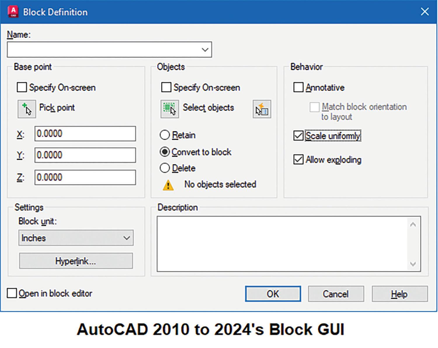
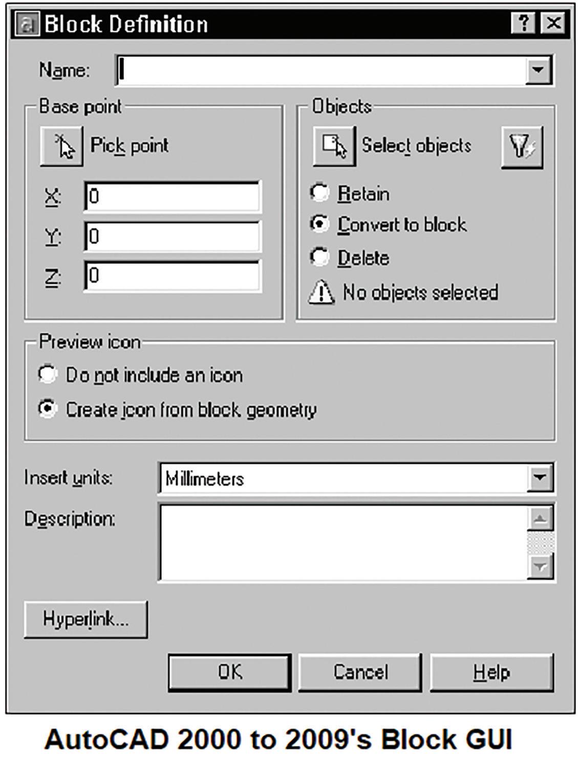
Note: To run the original command line version of the Block command you’ll have to precede the command name with a hyphen: -BLOCK
There’s still one final twist to BMake. Though the command BMake disappeared from AutoCAD 2000, 2000i and 2002, when AutoCAD 2004 came out in March of 2003, BMake miraculously resurfaced. This time though I would say it’s in spirit only. For some reason Autodesk decided to add an alias in the ACAD.pgp file so that when the BMake
command is entered AutoCAD would launch the Block command. This addition to the ACAD.pgp file has continued since that version to today’s AutoCAD 2024 (see Figure 20).
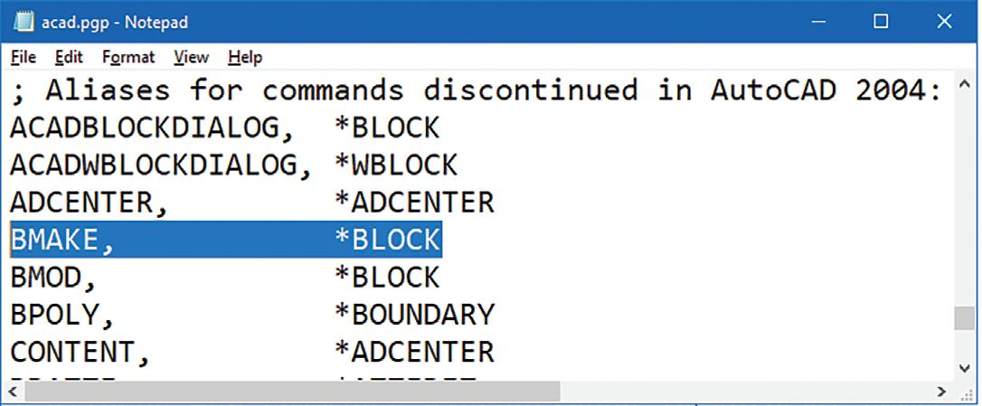
3. DDType.lsp
Back in the prehistoric days before the advent of fancy GUI Operating Systems (OS), commands were typed out on a dull, text character-based terminal. A number of these commands were built-in to the OS without a need for an external execution (EXE) file to run. Almost every known OS back then came with an internal command to view the contents of text files. In the Unix and Linux world this command is entered as: “cat”. For IBM PC / Microsoft’s Disk Operating System (DOS) this command is known as: “TYPE”.
In May of 1985 when AutoCAD released version 2.1 it took advantage of accessing DOS commands like TYPE by introducing the ACAD.pgp (which stands for Program Parameter) file. When these DOS command names are entered at the command prompt AutoCAD would read the information provided in the ACAD.pgp file and launch the
augi.com/augiworld October 2023 | AUGIWORLD Magazine 41 LISP Commands
Figure 18: BMake-r2000-2009
Figure 19: BMake-r2010-2024
Figure 20: BMake-pgp
corresponding referenced external DOS command (see Figure 21).
AutoCAD r12 in the Sample folder free for customers to use.
As long as DDType.lsp and DDType.dcl are located in one of AutoCAD’s Support File Search Paths entering the following command sequence at the command prompt successfully loads it: (load “DDType”)
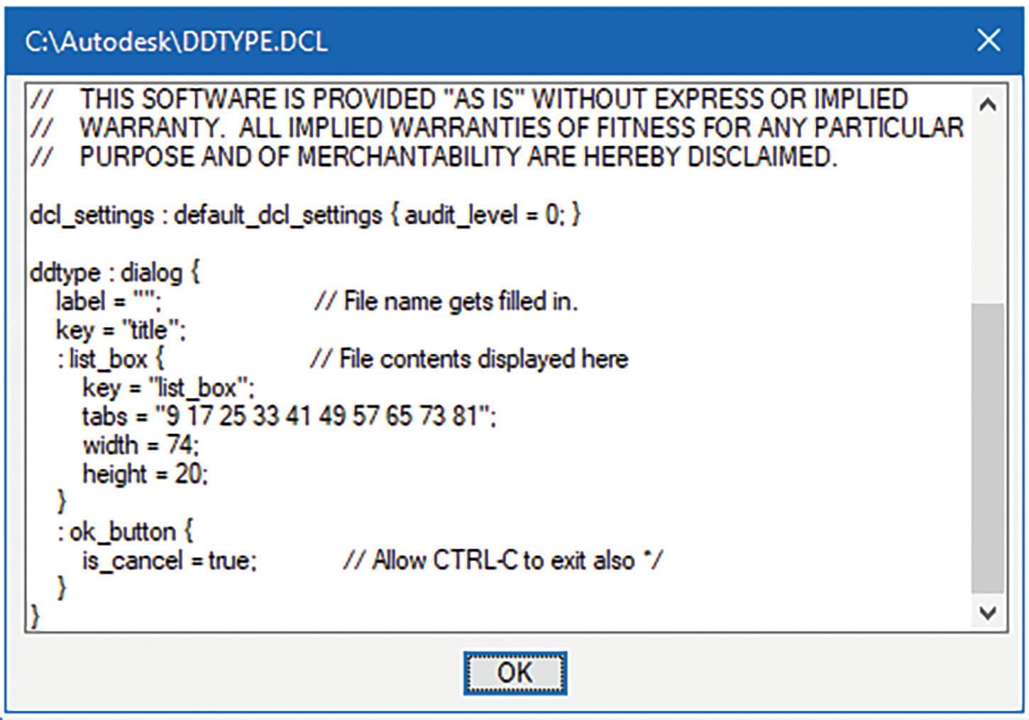
After successfully loading the code and entering DDType at the command prompt the following File to List selection window appears (see Figure 23):
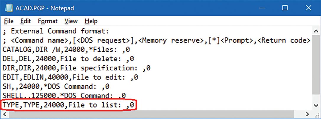
Note: AutoCAD did not support aliases or command shortcuts in the ACAD.pgp until October of 1990 when AutoCAD r11 came out.
Since AutoCAD is mainly a drawing-based program, it continued to rely on the external DOS TYPE command to view text files. Then with the release of AutoCAD r12 in June of 1992 adding support for programmable dialog boxes a developer by the name of Duff Kurland decided to take advantage of this new feature. Kurland in December of 1991 coded DDType.lsp and DDType.dcl to generate a GUI for the end user to select an external text file and display the contents inside a list box (see Figure 22).

By default, Kurland set the Files of type to only show “doc” files. But you can actually enter in the File name edit box any file type extension like “*.txt” or “*.bat” or even “*.*” and the file list window will update showing files that match the revised file type. Once a file is selected and the Open button is clicked another window appears displaying the file name in the title bar and the content in the list box for viewing (see Figure 24).
Apparently, Kurland chose to name his command “Type” to replicate DOS’s TYPE command. The “DD” prefix which means “Dynamic Dialog” was added to match AutoCAD’s promotional naming convention at the time for lisp functions that included the DCL GUI. This new DDType command was shipped with
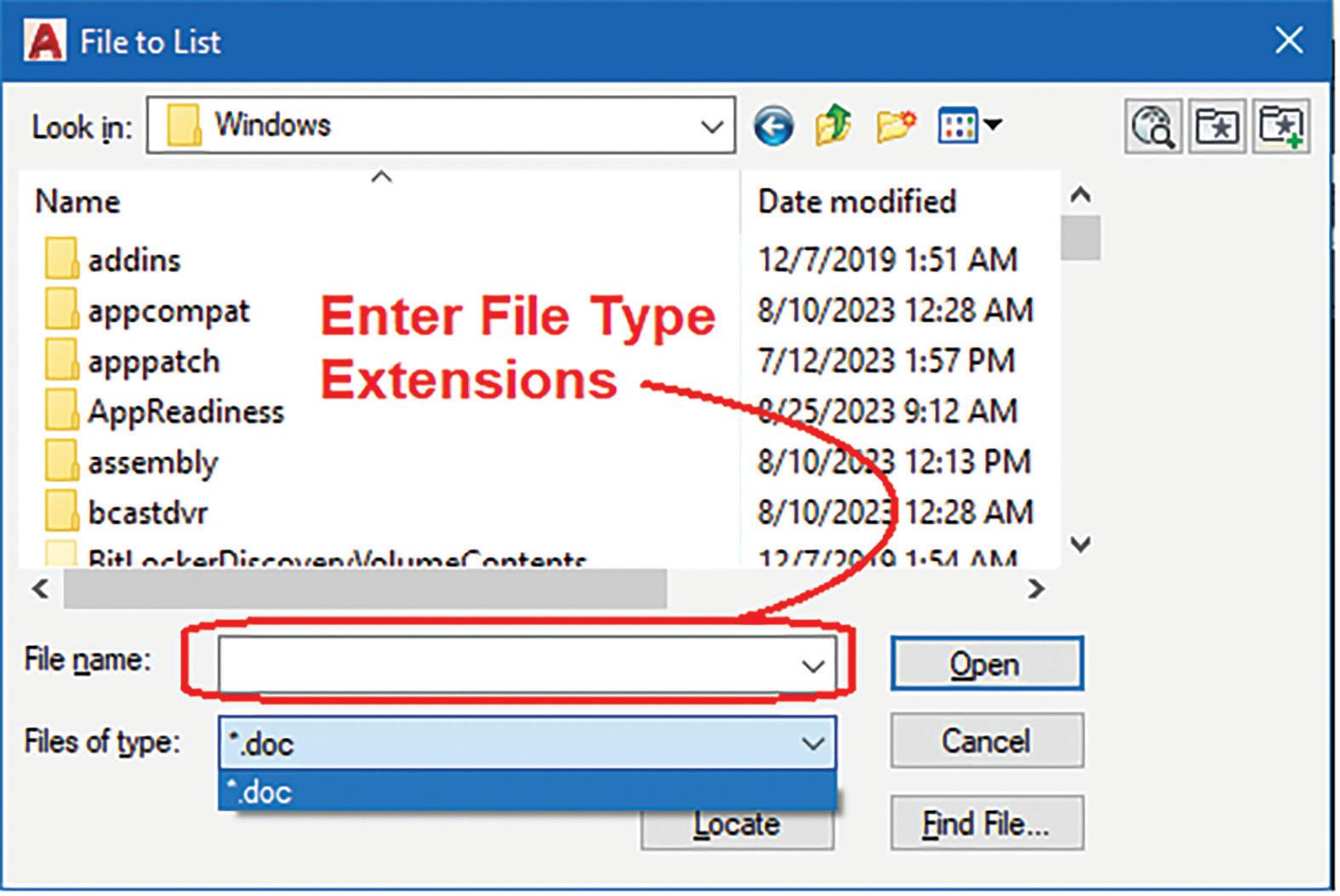
AUGIWORLD Magazine | October 2023 augi.com 42 LISP Commands
Figure 21: DDType Acad-pgp
Figure 22: DDType-lsp
Figure 23: DDType-r12-Select
Figure 24: DDType-r12-View
At the time, I was actually not aware of this free sample addition to AutoCAD. I made the mistake of not opening the AutoCAD folder to explore all the freebies that came with the product. Instead, I ended up coding my own text file viewer command I called DDBrowse.lsp. I purposely included in DDBrowse the following additional features:
1. The DCL file is written on the fly at run time so there’s no need for a separate DCL file to accompany the lisp code.
2. The GUI window is wider and taller so more of the text content can be seen without having to scroll up and down.
3. A Print button option is included so the contents of the text file can be sent to the printer (see Figure 25).
4. Find.lsp
Since its first release, another text related command missing from the AutoCAD program for over 15 years was the ability to first find and then replace text characters in the drawing. Finding and replacing text sounds like such a simple and important feature to include. But since AutoCAD is a drawing-based application, the need to add a command to search through paragraphs of text was definitely not a top priority.
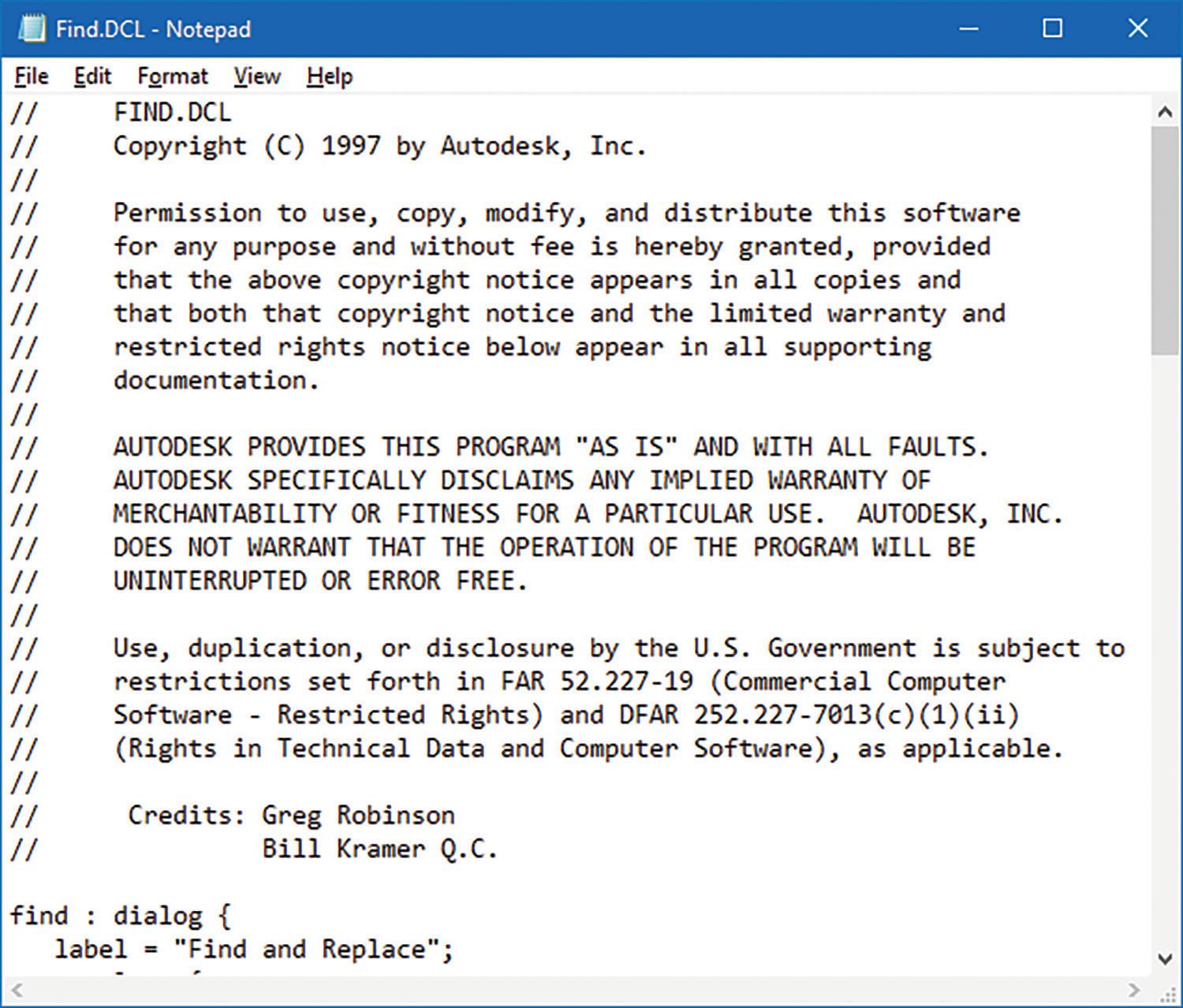
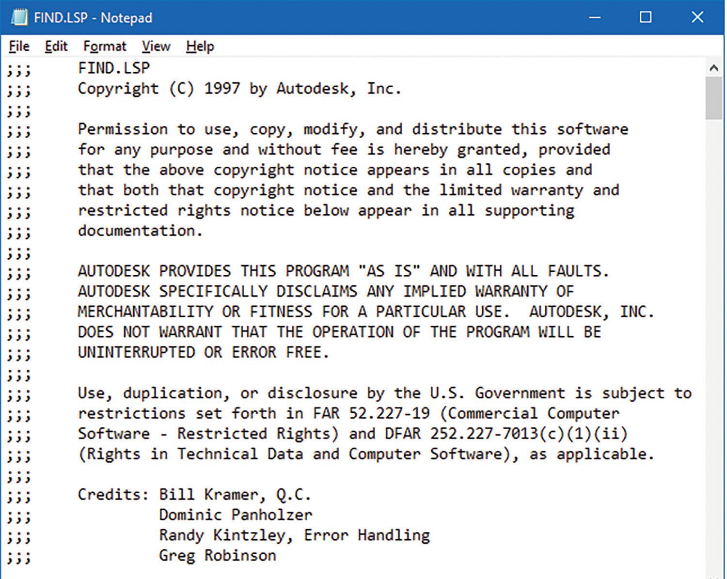
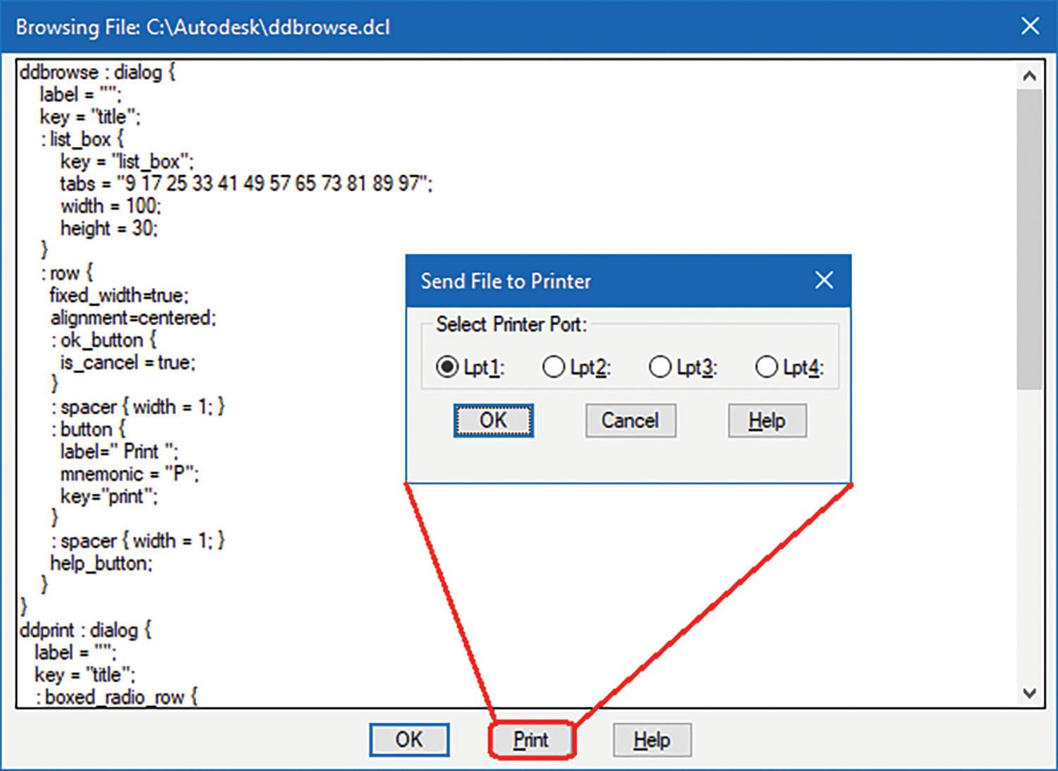
Finally, in 1997 a group of four developers Bill Kramer, Dominic Panholzer, Randy Kintzley and Greg Robinson came together to code a find and replace program called Find.lsp and Find.dcl (see Figure 26 and 27).
But after this initial free sample introduction to the DDType command the development came to a screeching halt. DDType.lsp and DDType.dcl were never included in any future releases of AutoCAD again. Unless you kept a copy, both of these files just faded into digital oblivion. AutoCAD even up to the current 2024 version has offered no equivalent command to match the DDType functionality. This is perhaps due to the following reasons:
1. The free sample was just a sample demonstrating what the new DCL can offer.
2. As the prevalence of DOS began to fade and the dominance of the new Windows OS began to take over, viewing text files was a breeze. It was just a matter of double clicking on a text file from Windows Explorer. The free built-in app Notepad would open the file content for both viewing and editing.
3. There was really no demand or need for a separate built-in command to view text files from within AutoCAD.
augi.com/augiworld October 2023 | AUGIWORLD Magazine 43 LISP Commands
Figure 25: My DDBrowse-lsp
Figure 26: Find-r14 Bonus-lsp
Figure 27: Find-r14 Bonus-dcl
LISP Commands
Autodesk then decided to package this code as part of the Bonus Tools with the release of AutoCAD r14 in February of 1997. The Bonus Tools Help window shows that FIND is only one out of an additional eight Text related commands added as a Bonus to the AutoCAD application. Autodesk definitely wanted to focus on adding more text related functions to AutoCAD (see Figure 28).
Note: When AutoCAD has a built-in matching command name there are two ways to run the lisp version. The first method involves multiple steps. First, execute the Undefine command and enter “Find” as the command to remove. Second, now you can run the lisp version by entering “Find”. Lastly, after the lisp version has completed, execute the Redefine command to restore the built-in “Find” command back. The second method, which is what I recommend, is to enter at the command prompt the following to call the lisp function: (c:find)
After executing the lisp version, the Find and Replace window appears (see Figure 29).
Since Find.lsp is part of the Bonus Tools package, there are a number of functions stored in a file called AC_Bonus.lsp shared by the other Bonus lisp files. So, in order for the code to load successfully, AC_Bonus.lsp has to load first by entering the following at the command prompt: (load “AC_Bonus”)
Once these shared functions are loaded and as long as Find.lsp and Find.dcl are located in one of AutoCAD’s Support File Search Paths then enter the following at the command prompt to successfully load it:
(load “Find”)
This is a very simple GUI that requests information prior to running the find and replace operation. In addition to edit boxes there are two toggle button options to refine the search. On the Find edit box enter text characters to look for. On the Replace With edit box enter text characters to replace with. By the way, I discovered that the “Replace With” edit box can be left empty. Then when a text match is found it will actually replace the text with nothing. Does that mean that a new invisible Text object is created? Should I now talk about “The Invisible Man?” No, I better not get sidetracked again but instead stay focused on finishing the topic at hand.
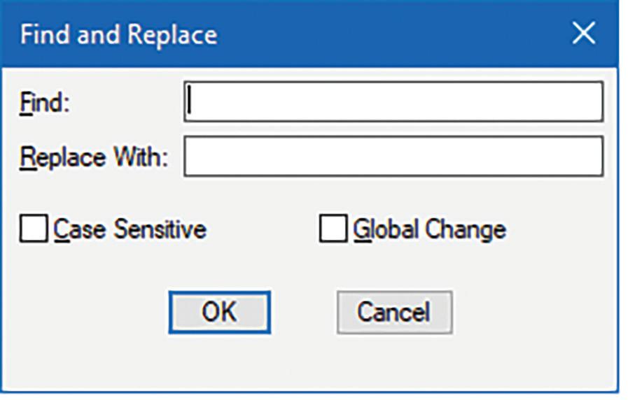
Though this added Find command makes-up for this missing text feature in AutoCAD, it does have the following limitations:
1. Only Text objects are searched but Attributes, MText and Dimensions are not supported.
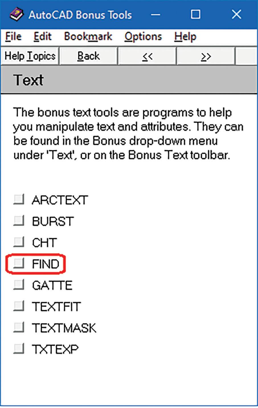
2. There’s no feedback provided as to how many Text objects matching the pattern are found and replaced.
3. After the command finishes regardless of
AUGIWORLD Magazine | October 2023 augi.com 44
Figure 28: Find-r14 Bonus Help
Figure 29: Find-r14 Bonus
success or failure the following message always appears at the command prompt: “Changing text (100%).”
Unfortunately, this very simple but effective Find and Replace command met a similar fate as DDType. Both Find.lsp and Find.dcl were dropped permanently with the release of AutoCAD 2000 in March of 1999. There were two major reasons for the quick death:
1. AutoCAD 2000 introduced a more sophisticated built-in Find command.
2. The Bonus Tools were transitioned to Express Tools, and this resulted in some of the lisp functions like Find to be left in the dust (see Figure 30).
Now with AutoCAD’s new Find command, included are a number of Options such as searching for more than just Text objects but also Block Attributes, Dimensions, Hyperlinks and MText. This new and improved GUI would remain fairly unchanged from AutoCAD 2000 through 2010 (see Figure 31).
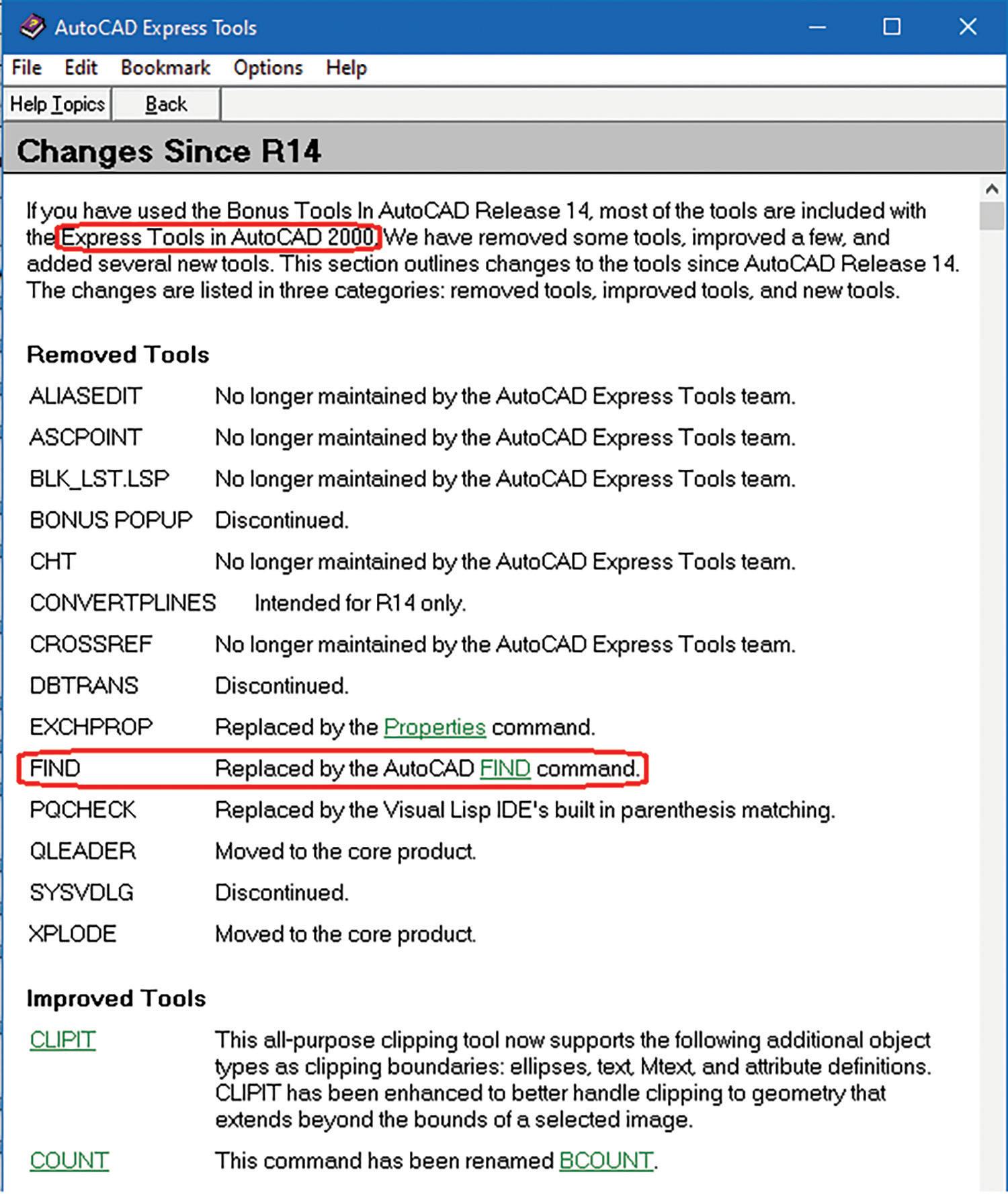
Then starting with AutoCAD 2011 released in March of 2010 till the current version of AutoCAD 2024
the Find and Replace GUI was given a brand-new facelift and additional features. The found objects can now be shown in a window that expands when the List results toggle button is checked. Options, a lot more of them, are now positioned at the bottom of the window and can also be expanded or collapsed for selection (see Figure 32).
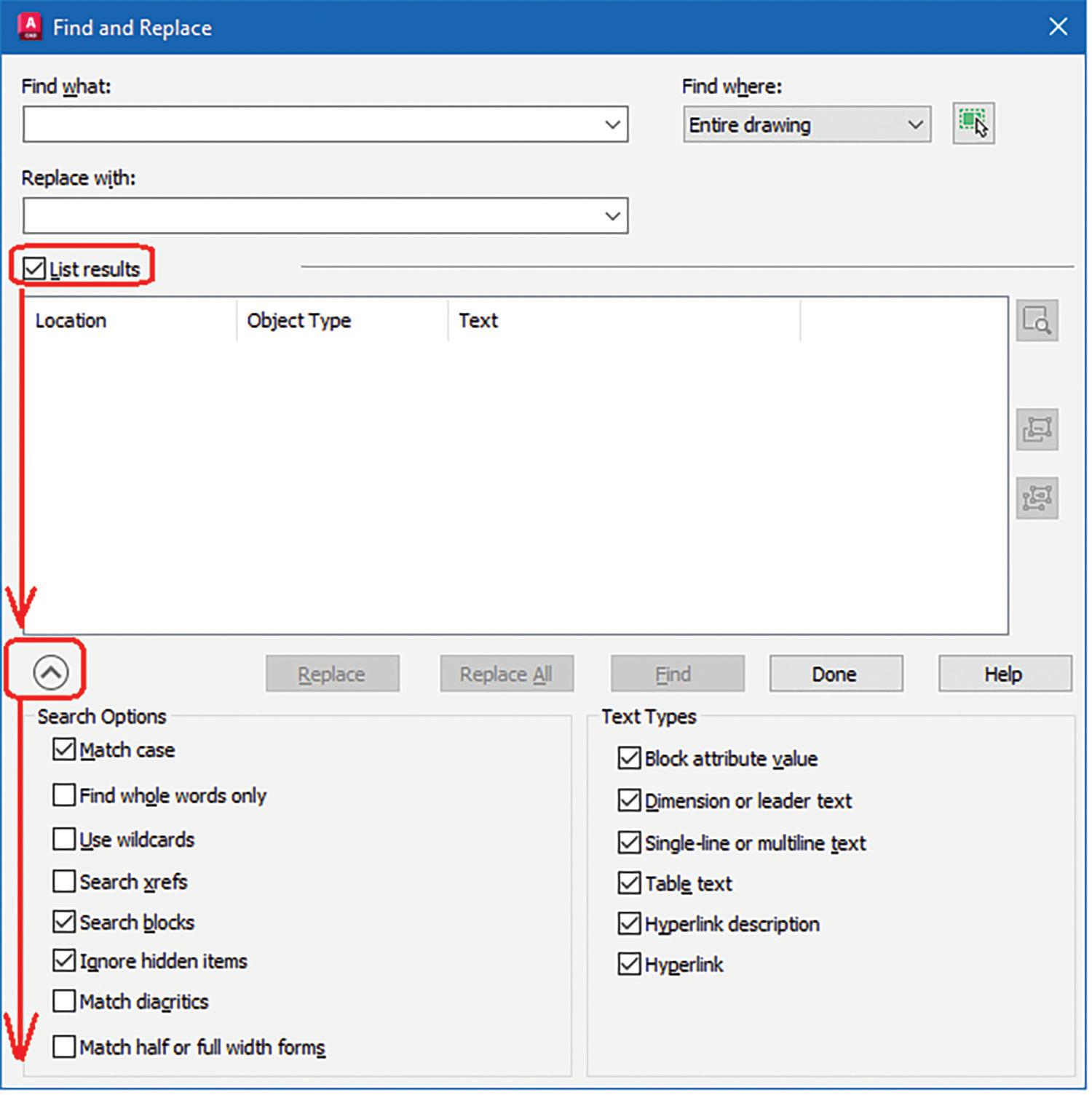
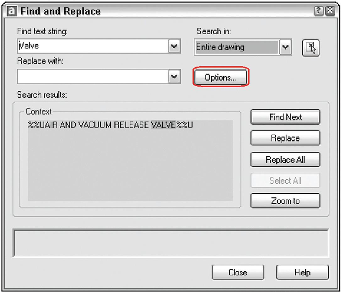
ON WITH THE SHOW
[Insert Figure 33-Free Sample History Table.png] I’ve placed in a table listing the development
augi.com/augiworld October 2023 | AUGIWORLD Magazine 45 LISP Commands
Figure 30: Find-r2000 Express Tools Dropped
Figure 31: Find-r2000-2010
Figure 32: Find-r2011-2024
history of all four lisp files discussed. Hopefully I’ve piqued your interest on the many free sample lisp files available from previous up to the current version of AutoCAD. These freebies once again remind me of the many festivities accompanying the arrival of the upcoming Halloween season. Now that the pandemic is over, entire city streets may be shut down so that trick or treaters can stroll up and down the block entering one store after another to collect lots of free candies. Likewise, it’s time for you to crack open the AutoCAD folder and check out one lisp file after another to discover the many free gems available at your fingertips.

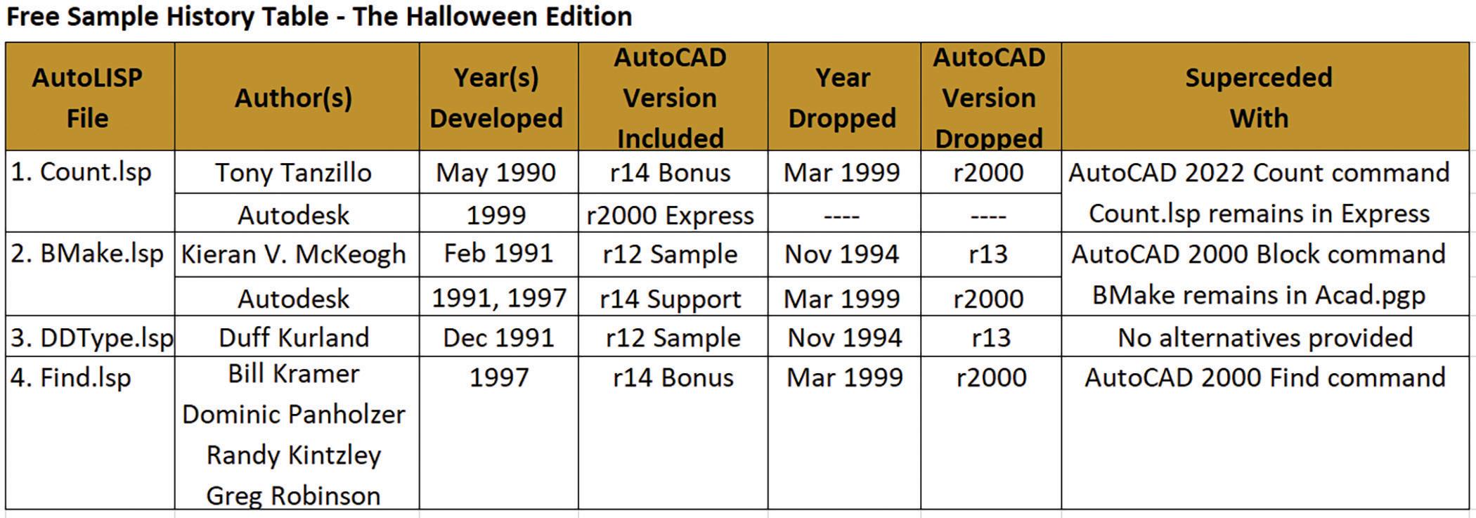
Mr. Paul Li graduated in 1988 from the University of Southern California with a Bachelor of Architecture degree. He worked in the Architectural field for small to midsize global firms for over 33 years. Throughout his tenure in Architecture, he has mastered the use and customization of AutoCAD. Using A utoLISP/ Visual Lisp combined with Dialog Control Language (DCL) programming he has developed a number of Apps that enhance the effectiveness of AutoCAD in his profession. All the Apps actually came out of meeting challenging needs that occurred while he worked in the various offices. He has made all the Apps available for free and can be downloaded from the Autodesk App Store. Though he recently retired from the Architectural profession, Paul continues to write articles depicting his past work experience. Some of these articles can be found in AUGIWORLD Magazine where he shares his knowledge learned. Paul can be reached for comments or questions at PaulLi_apa@hotmail.com.

AUGIWORLD Magazine | October 2023 augi.com 46 LISP Commands
AUGIWORLD brings you recent developments in Autodesk and related software items

Bright Ideas for a Bright Future
AUGIWORLD brings you the latest tips & tricks, tutorials, and other technical information to keep you on the leading edge of a bright future.