 Ahmad Sultan
ahmad.sultan.gr.sciarc@gmail.com
a.sultan.ahmad
Ahmad SultanSelected Works

 Ahmad Sultan
ahmad.sultan.gr.sciarc@gmail.com
a.sultan.ahmad
Ahmad SultanSelected Works
Ahmad Sultan
Selected Works
2016-2024
 Ahmad Sultan
As an architect at SRDW (SR DesignWorks), I work on various types of projects, from commercial to residential, at different phases of design, from concept to construction. I compile and correct construction documentation sets, put together presentations for clients, and make digital 3D models for rendering purposes.
Having recently worked at WATG, I have become familiar with a fast-paced US working environment. I was involved in Hospitality projects of multiple scales, from Urban Design to Hotels to Individual residences. My tasks included preparing presentations for clients (Hard Rock Resort and Casino), modelling and rendering images of proposed changes (Lido Hotel), responding to RFIs (Coba residence) and fixing construction drawings and compiling Construction Documentation sets to be submitted to the city (L’Ermitage Hotel), among others.
My previous experience is in Pakistan, working on projects of various types and scales, including Corporate Headquarters (Telenor 345, a multiple award-winning project nominated for a World Architecture Festival award), Public Healthcare ($100 million Punjab Kidney and Liver institute) and Education (in collaboration with the internationally renowned Agha Khan Foundation).
Having recently graduated from Sci-Arc, I believe that Architecture holds the answers to many important questions that are beginning to be asked about our future, especially with the effects of climate change and a burgeoning population beginning to make themselves known.
My interests include urban design projects, vernacular architecture, and emerging architecture in the global south.
 Ahmad Sultan
DS: Design Studio
VS: Visual Studies
AS: Advanced Studies
HT:
SRDW
Supervisor:
Rashid Rasheed
Design Phase: Schematic Design
Software Used: AutoCAD, SketchUp
- I was responsible for digitally modelling a shading screen to act as a unifying between an existing and a proposed extension of the provincial HQ of the Muslim Commercial Bank building.
- Render below shows the fully developed model with shading screens, a terrace as well as landscaping added before being transferred to the rendering team for further development.
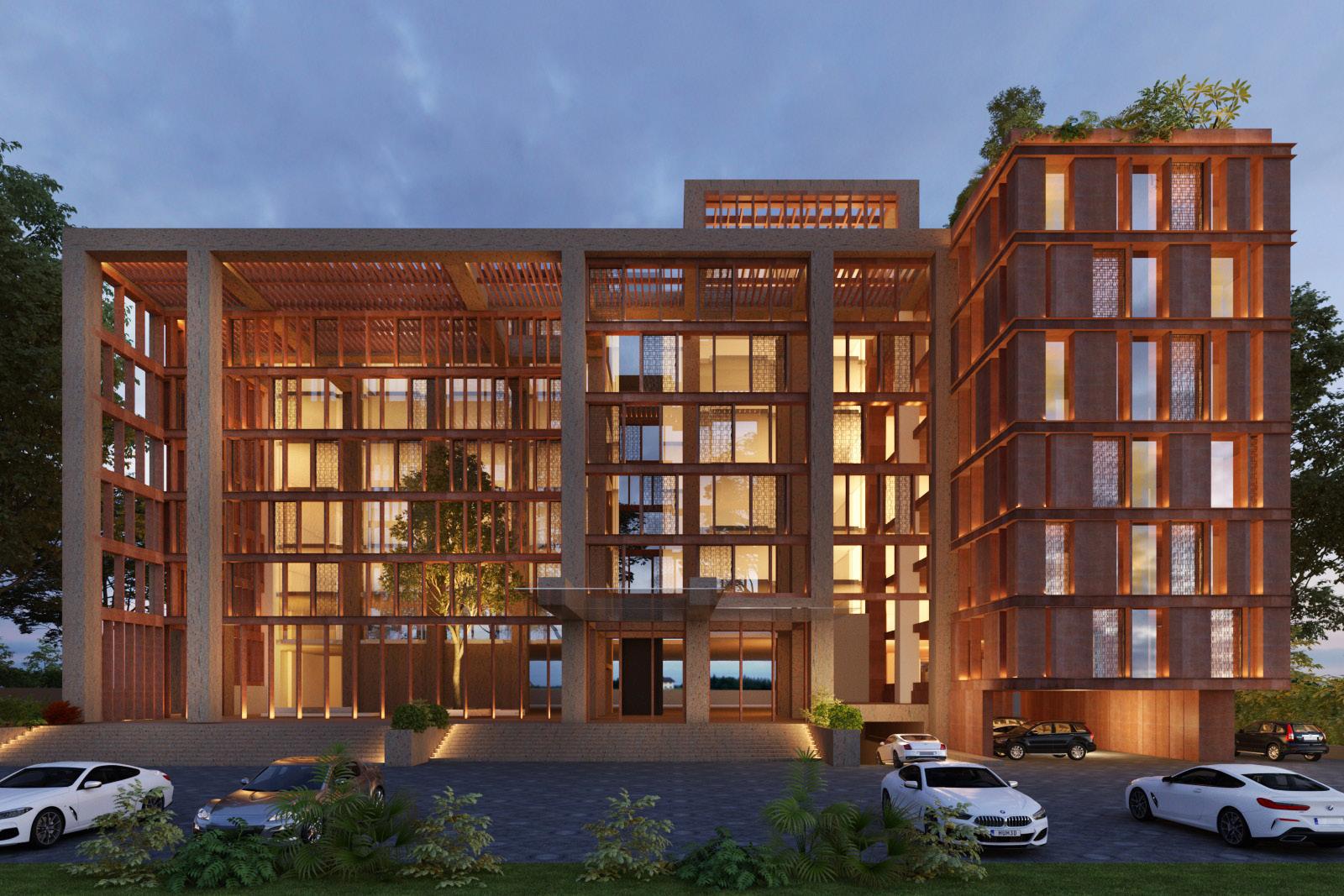
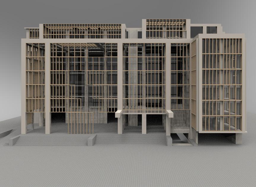
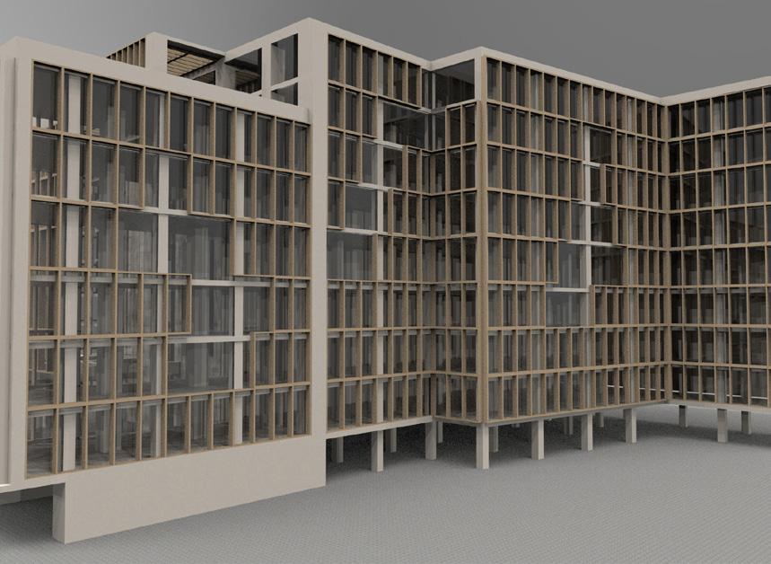
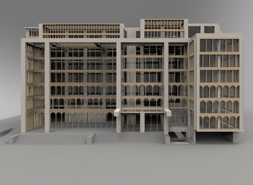
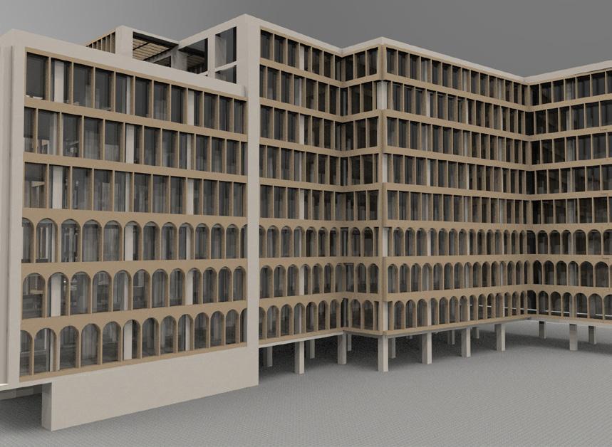
- I had three days to conceptualise various options, move forward on approved version and get it to rendered in time for meeting with client. Two of the developed options are shown above.
SRDW
Supervisor:
Shehzar Khan
Design Phase:
Design Development
Software Used: AutoCAD
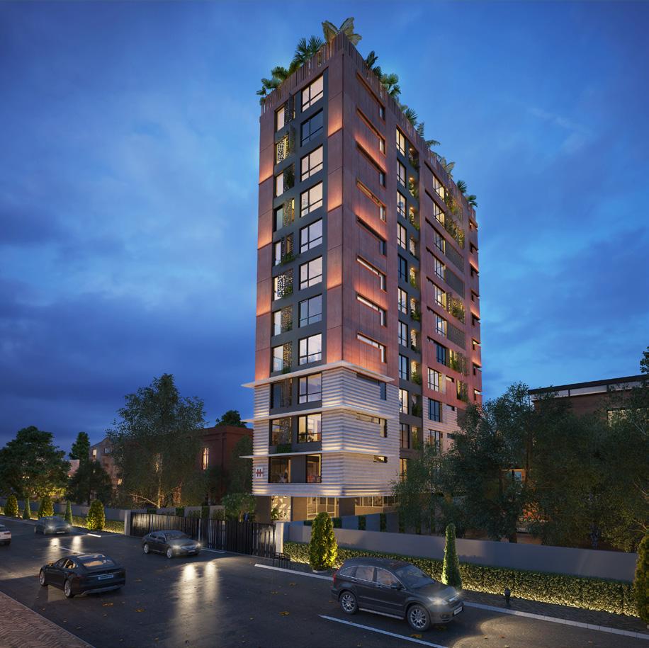
- I was responsible for correcting drawings and compiling the Construction Documentation set for Submittal to contractor.
SRDW
Supervisor:
Shehzar Khan
Design Phase:
Schematic Design, Design Development
Software Used: AutoCAD, SketchUp
- I was brought into this project at the end of the SD phase. I was responsible for changing/updating floor plans (under direction of a supervisor) when the client changed his mind about the form of the building.
- My other main responsibility on this project was to build the digital 3D model of the project from the ground up. I utilised SketchUp for this purpose.
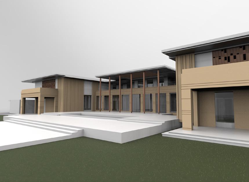
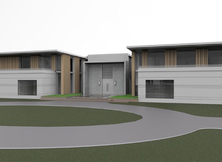
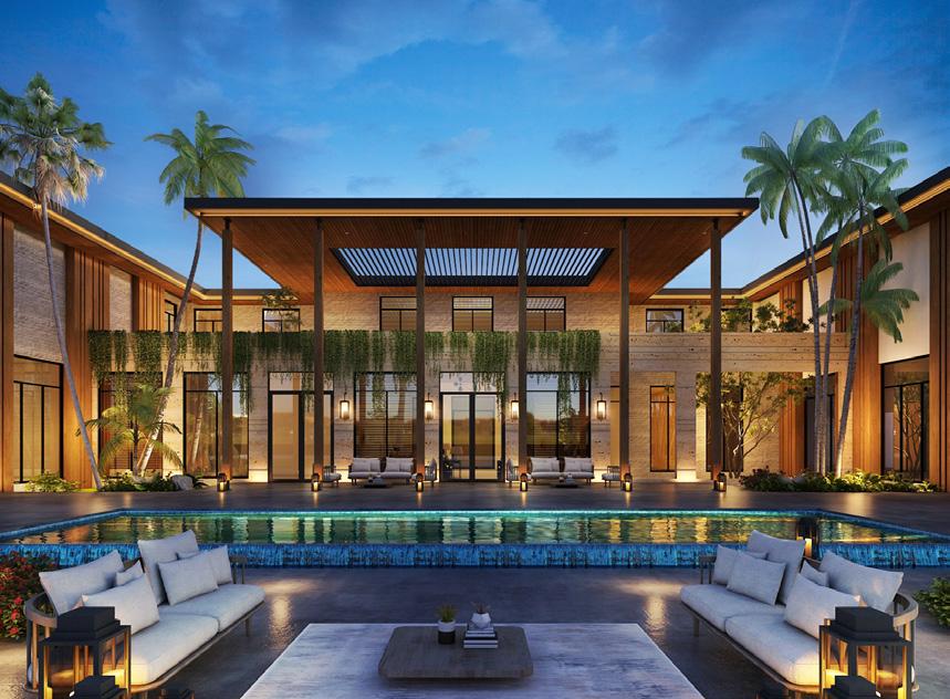
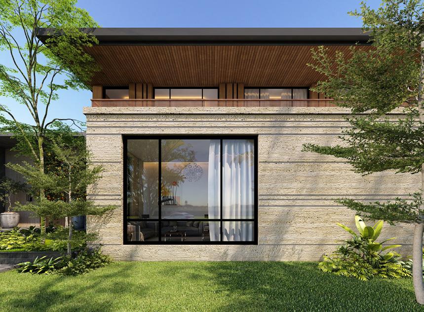
- Various iterations of this model were used as a base to generate renders (by inhouse team) to show the client for final approval.
- The approved fully resolved Sketchup model/renders were then used to draft updated AutoCAD plans.
WATG
Supervisor:
Mamta Imgle
Design Phase:
Schematic Design
Software Used:
SketchUp
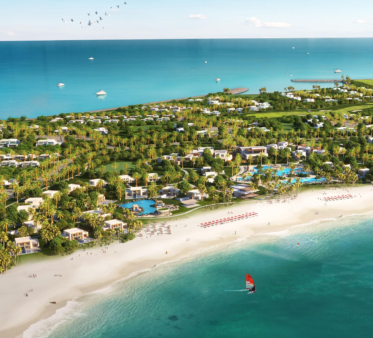
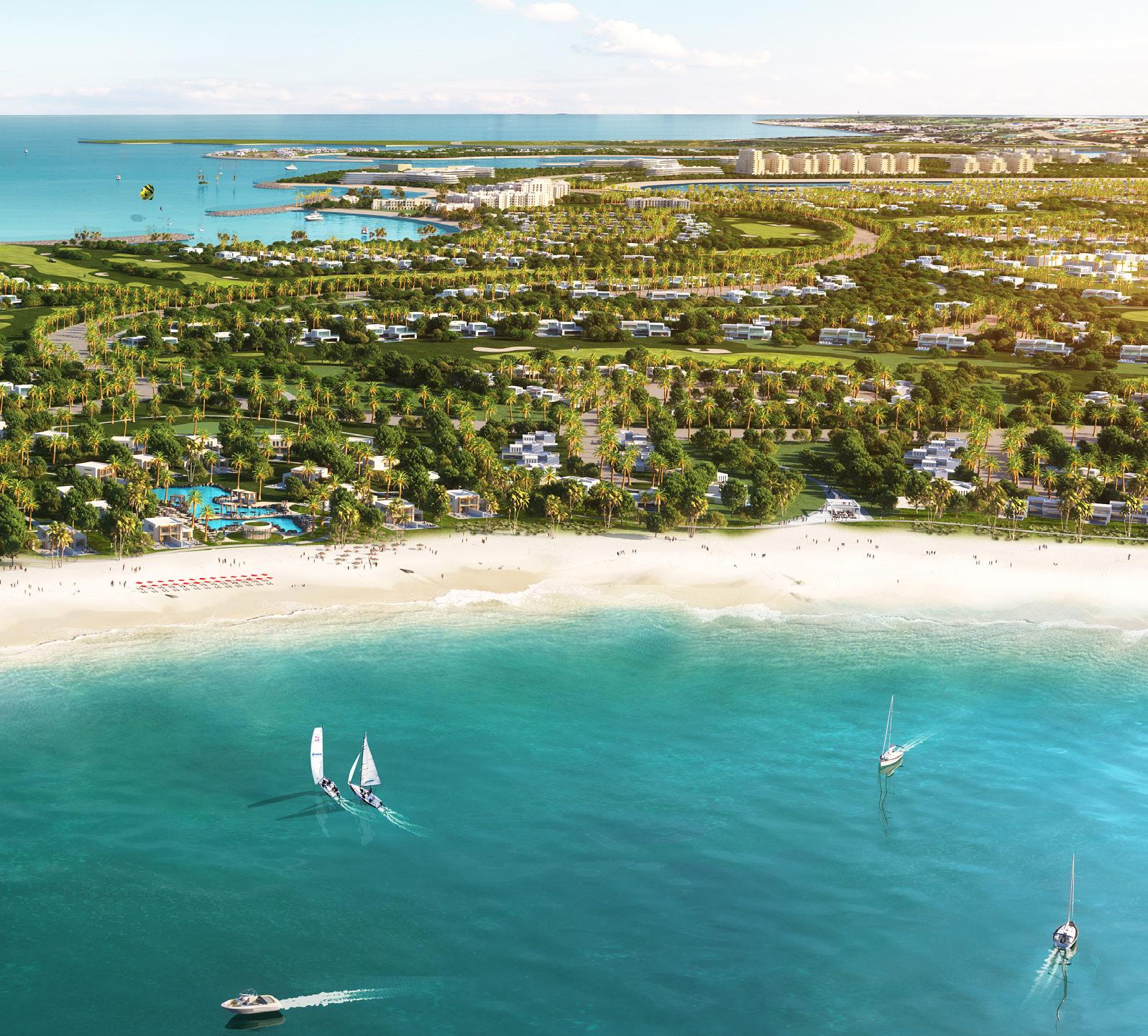
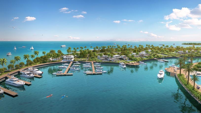
- I was responsible for making digital models of different types of residential units, as well as community spaces.
- These models were based on character imagery chosen by the client after initial consultations. Renders were outsourced.
Supervisor:
Greg Villegas
Design Phase:
Schematic Design
Software Used:
SketchUp, Lumion
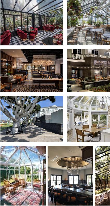
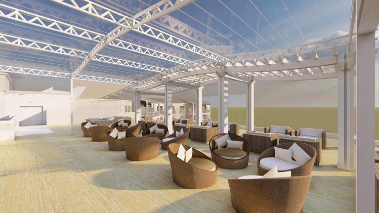
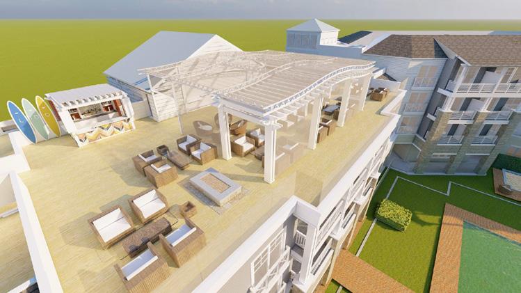
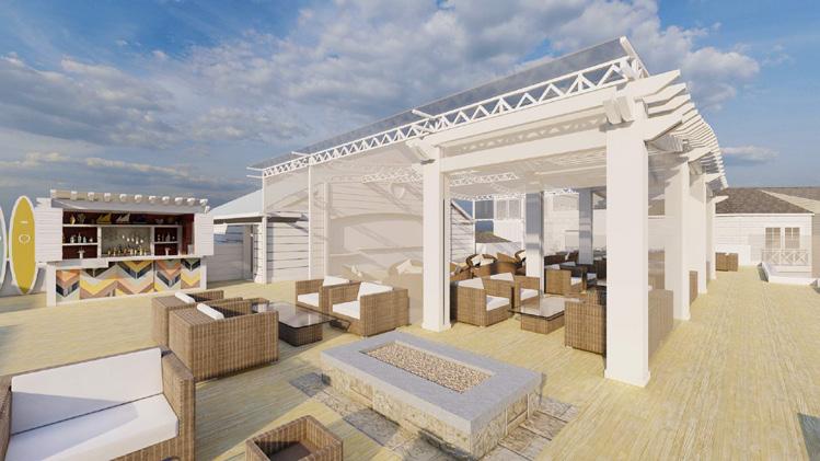
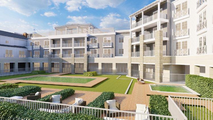
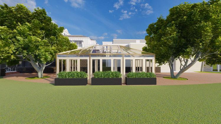
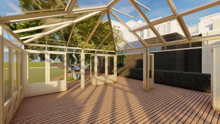
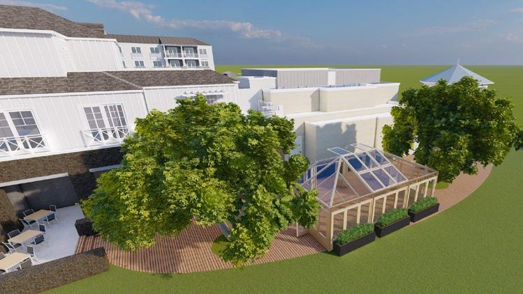
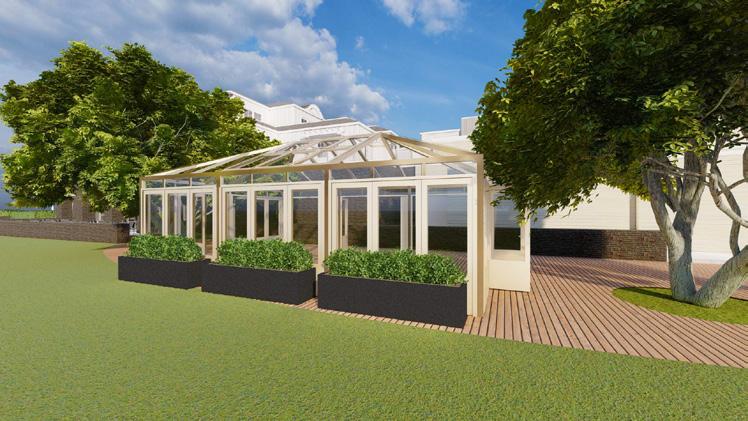
- I was responsible for making digital models of a Greenhouse Restaurant and a Rooftop Bar for a proposed expansion of Lido House Hotel in Newport Beach. Multiple iterations of models were made, the final of which are shown here. These models were based on character imagery chosen by the client after initial consultations.
- I was also responsible for rendering the SketchUp models in Lumion and composing images to show to the client as part of a formal presentation. All work on this page is mine.

Supervisor:
Mark Yoshizaki
Design Phase: Design Development
Software Used: Photoshop, InDesign
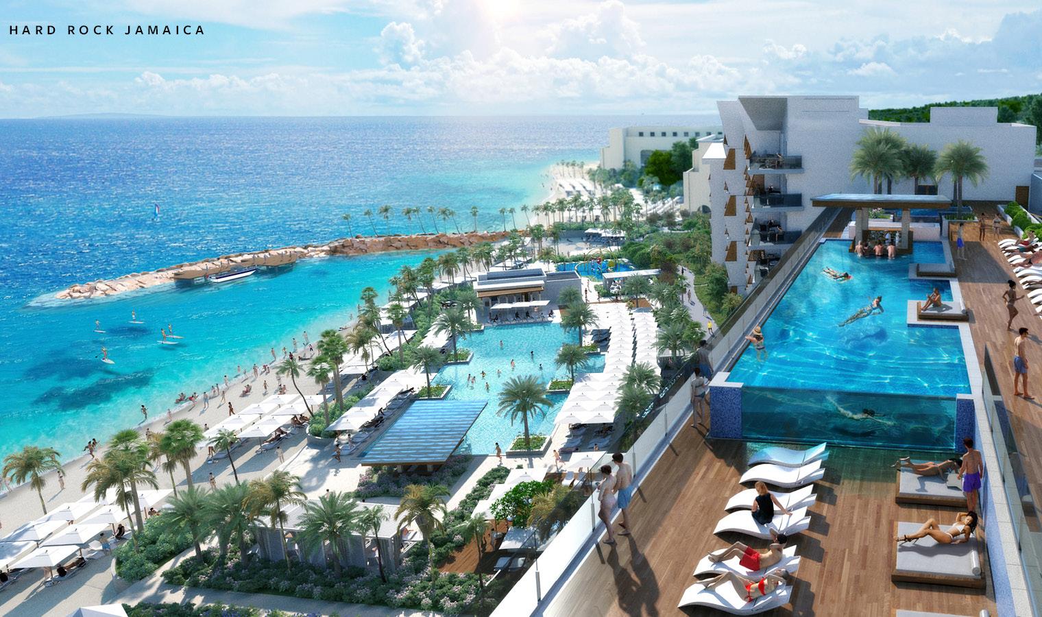
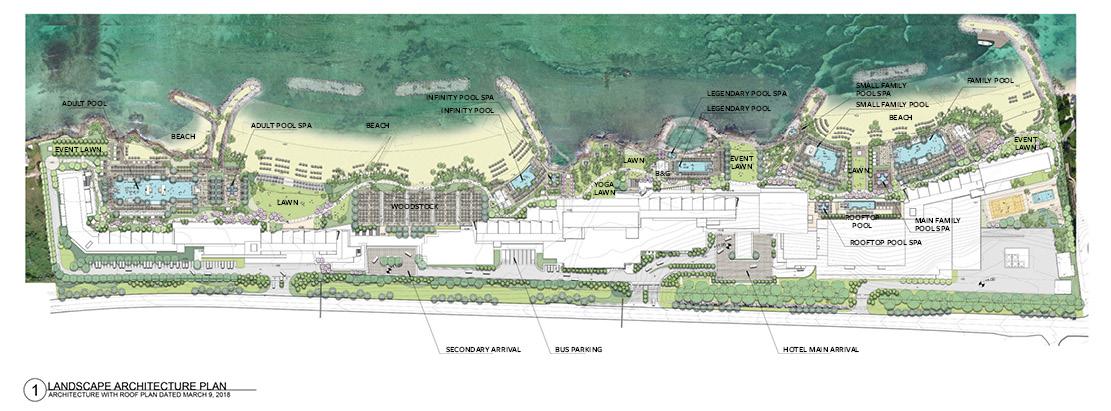
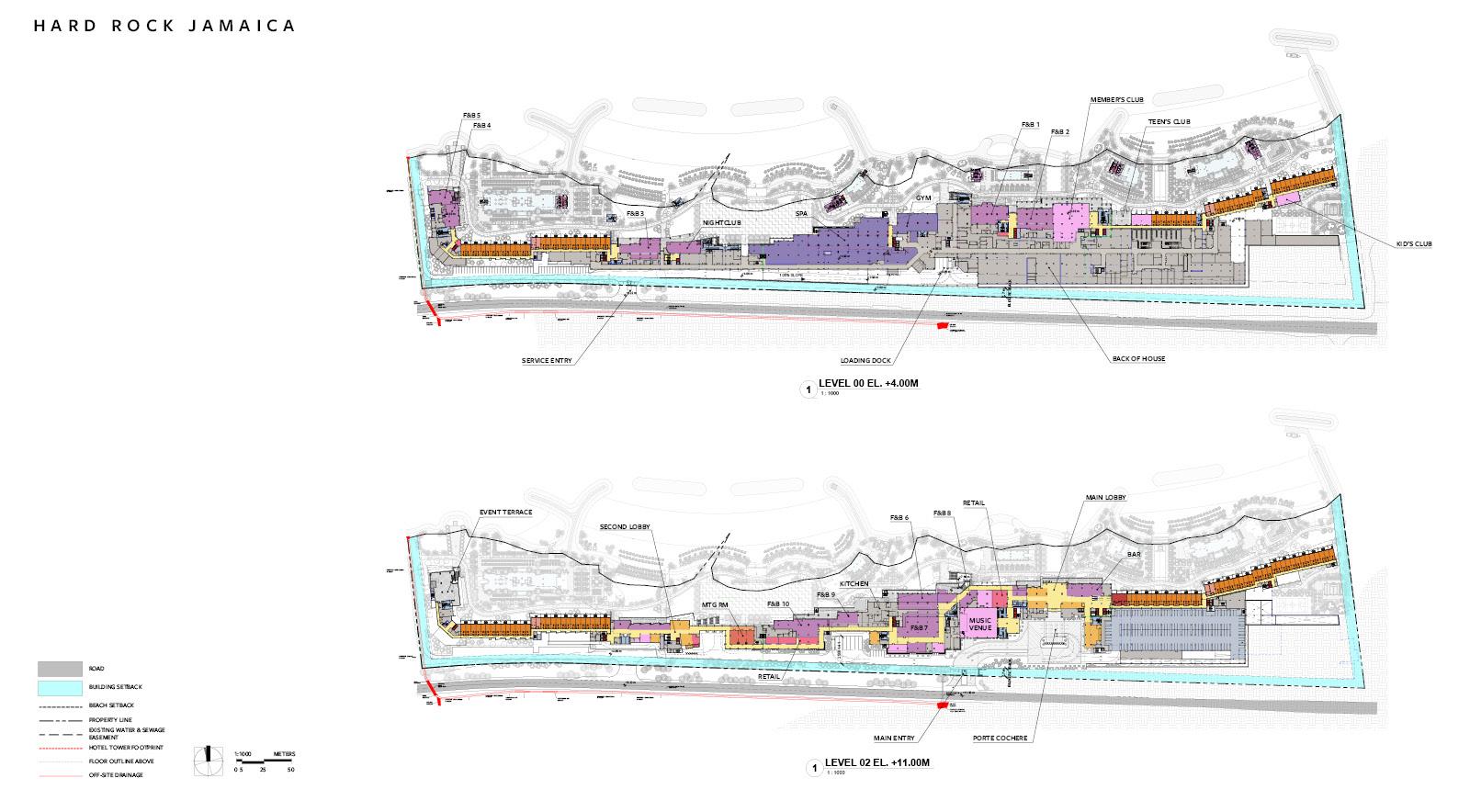
- I was responsible for generating images for client presentations using Adobe Photoshop and Adobe InDesign.
- Images shown on the right are my work. Renders were outsourced.
Supervisor:
Ashkan Afshari
Design Phase:
Design Development
Software Used:
AutoCAD, Revit, InDesign
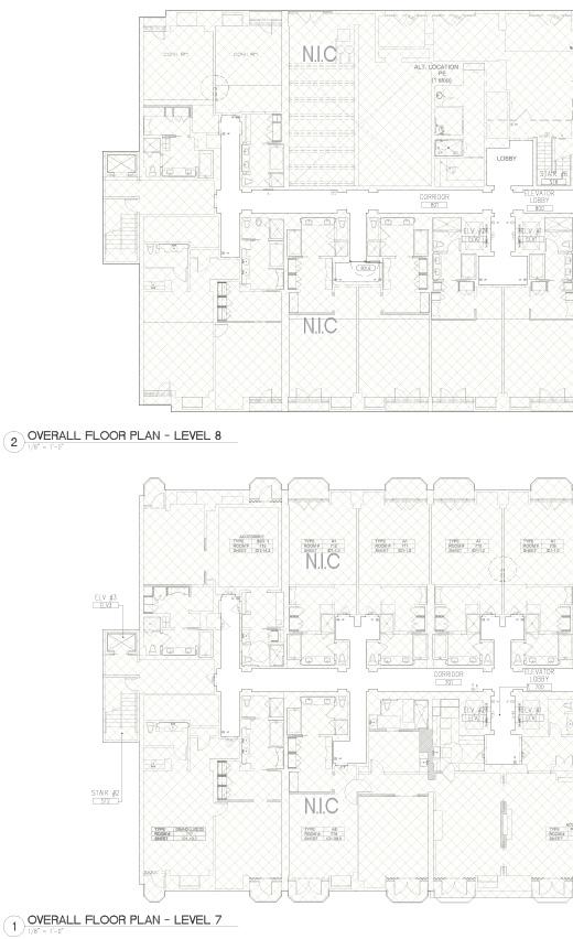
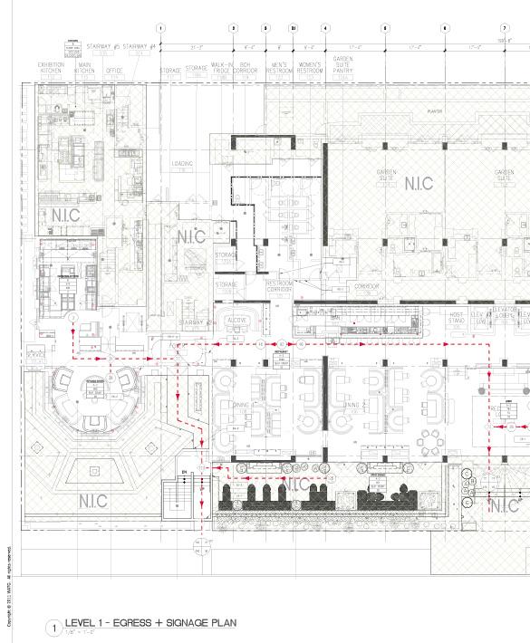
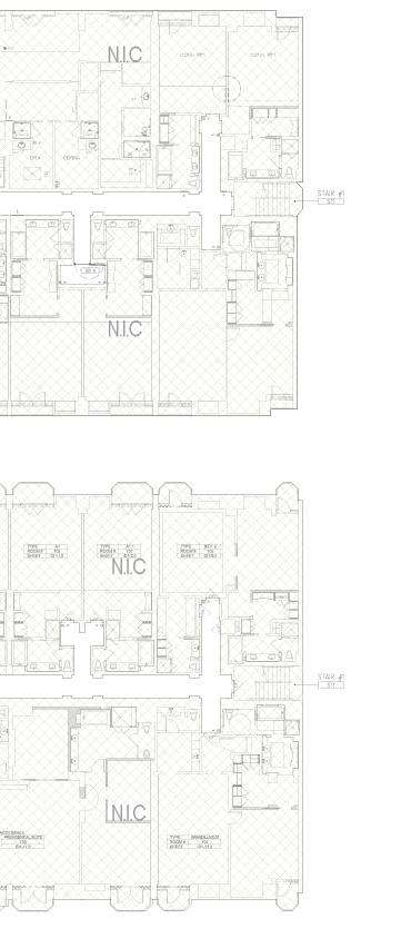
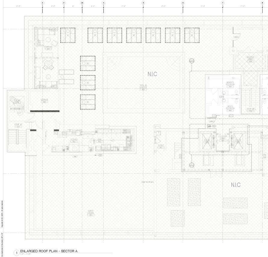
- I was responsible for correcting drawings and compiling the Construction Documentation set for Plan Check Submittal.
- I was also responsible for generating images for client and preparing client presentations using Adobe InDesign.

Shrouded Figure
DS 4000
Instructor:
Jenny Wu
2nd Year Advanced Vertical Studio
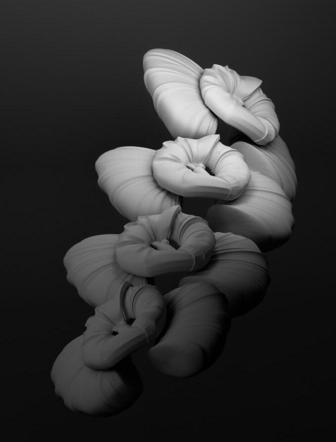
The studio explores the scale of material and its assembly. Students will be developing their own collection of details based on the properties of fabric and techniques of dressmaking.
How do the techniques of creating a seam, a crease, a drape, and/or a stitch translate to a set of
articulated methods of assembly in architecture? What are the architectural possibilities for the third element, the pillow or the stuffing, that lies between the body and the garment? We will design our own ‘textile’ which cannot exist in the scale of body, but only in architecture.

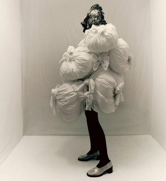
Rei Kawakubo’s wraps were taken as an inspiration for this project. Her ‘Comme des Garçons’ collection has a number of items whose quality stems from the varying nature of the material’s wrapping and how this expresses itself in varying ways depending on the qualities of the material used.
The image above shows initial experiments to understand the fundamental qualities of the wrapped condition and how it can be translated into a digital 3d model.

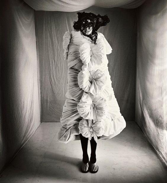
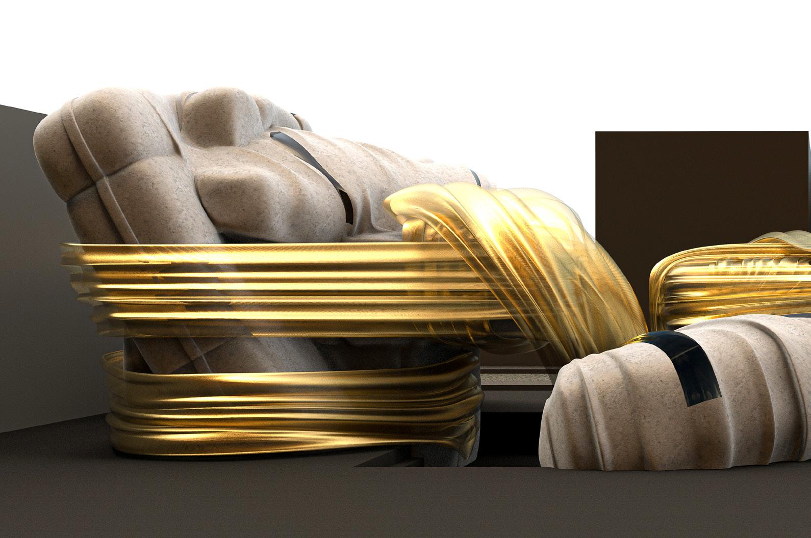
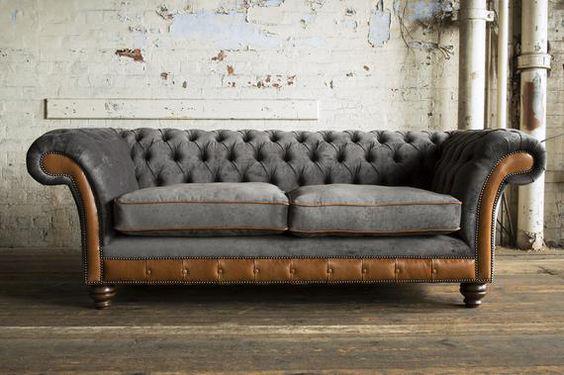
Rei Kawakubo’s wraps were taken as a departure point of this project, while the inside object was developed using a simple chesterfield patterned couch. The quality of the fabric and its wrapping changes as it wraps itself around the inner object, sometimes flowing, sometimes tight, sometimes leaving spaces where one can look inside, a reveal.
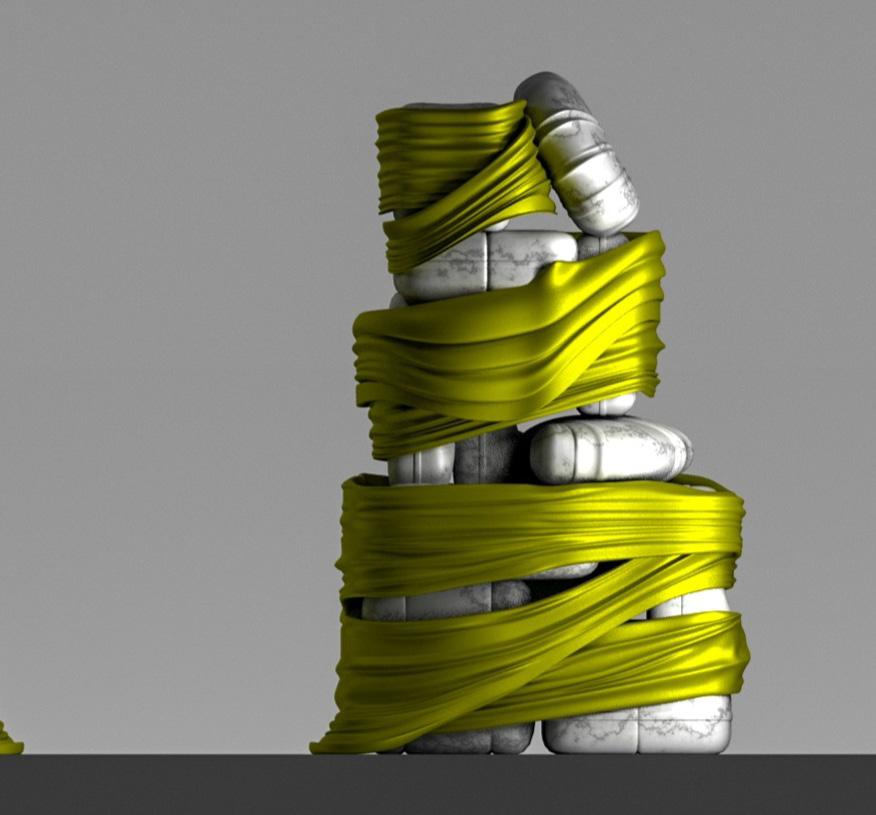
Many interesting moments occur, like the one seen here where the fabric itself ends, leaving a ‘cushion’ free but where it imparts its imprint on that unwrapped cushion.
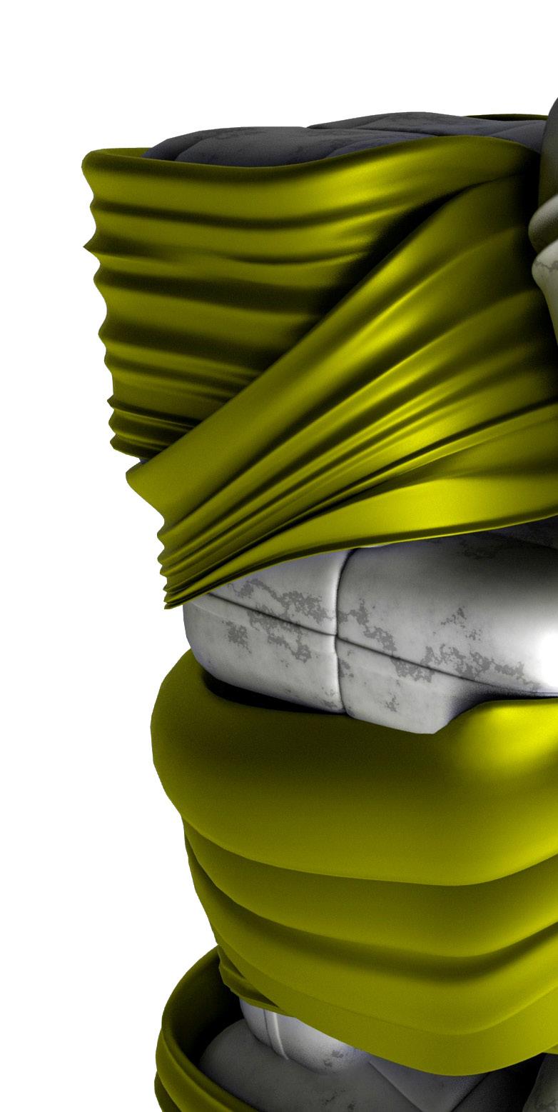
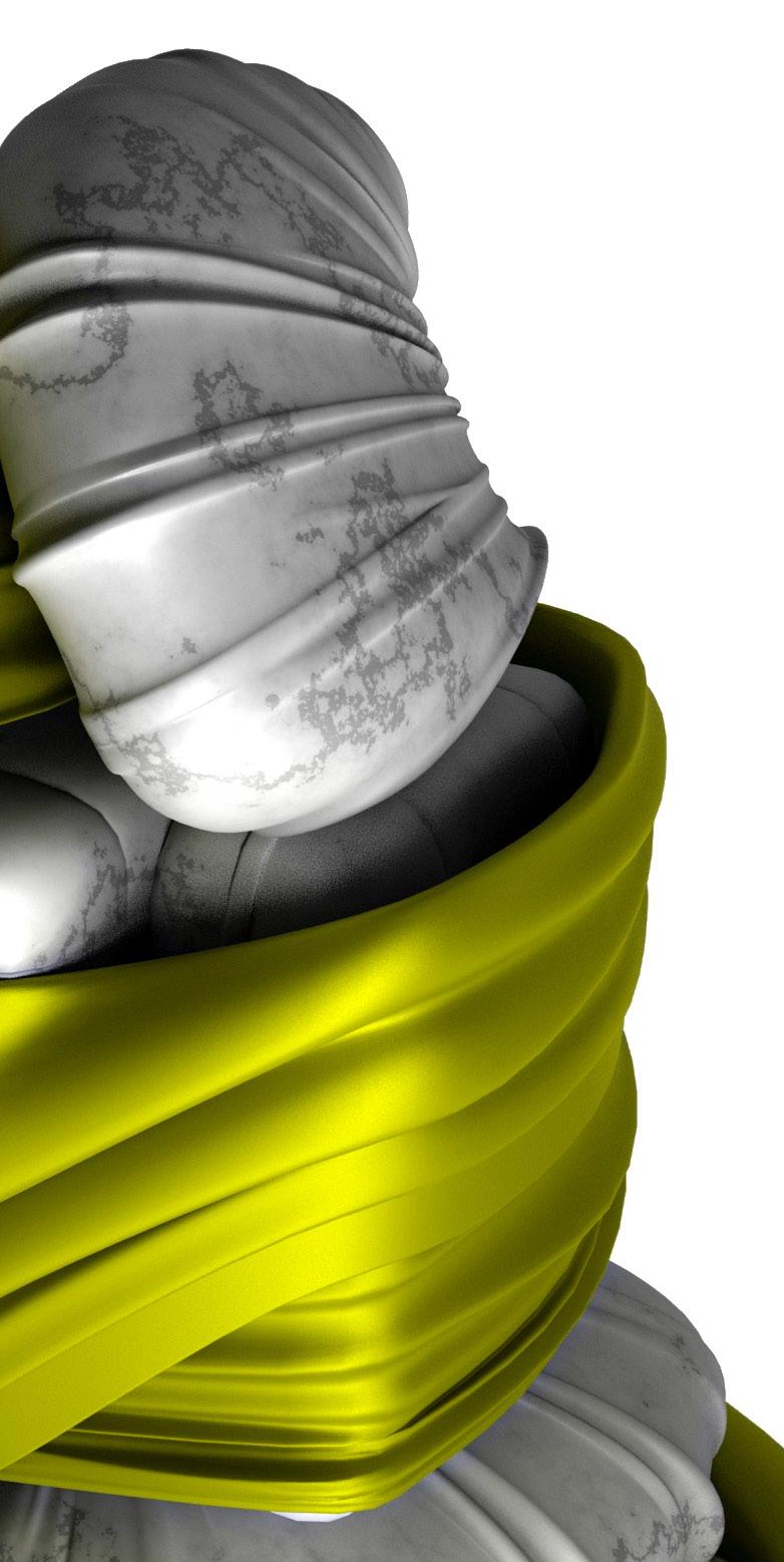

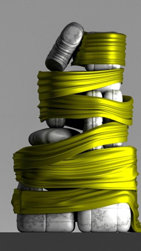
Many interesting moments can be seen here where the quality of the wrap is continuously changing.
It is tight in the beginning, spills over at a corner before making its way up the structure. In places it leaves gaps where the inner object is revealed, whereas in other places it becomes quite loose and, freed from the dictates of the inner object, is liberated to take up its form dependent on its own indigenous qualities.
It ends at the top where it begins to impart its own textural qualities on to the inner objects themselves, which are uncovered.


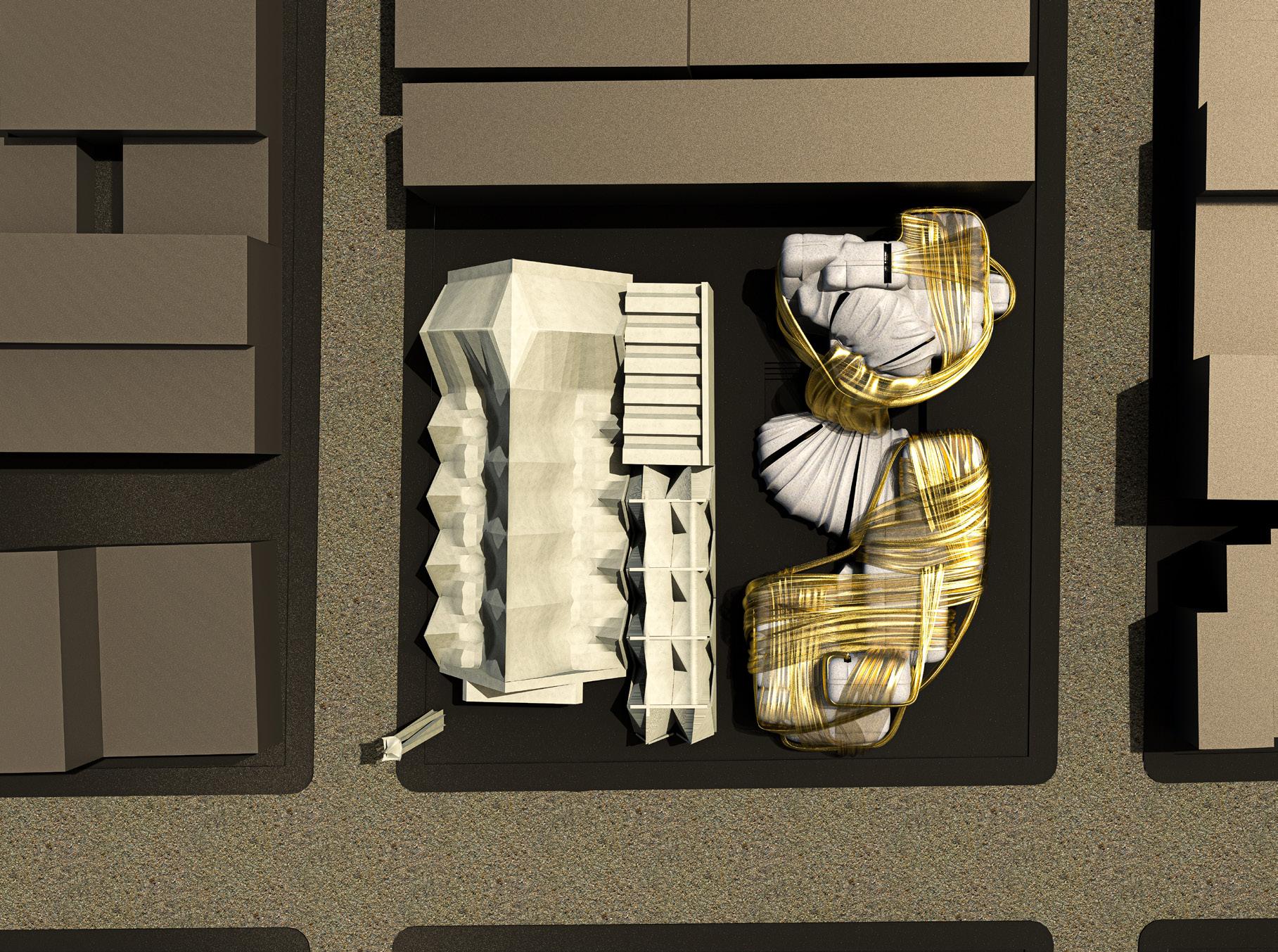
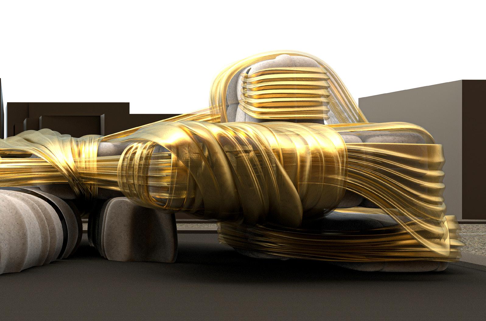
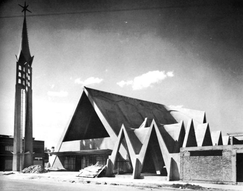
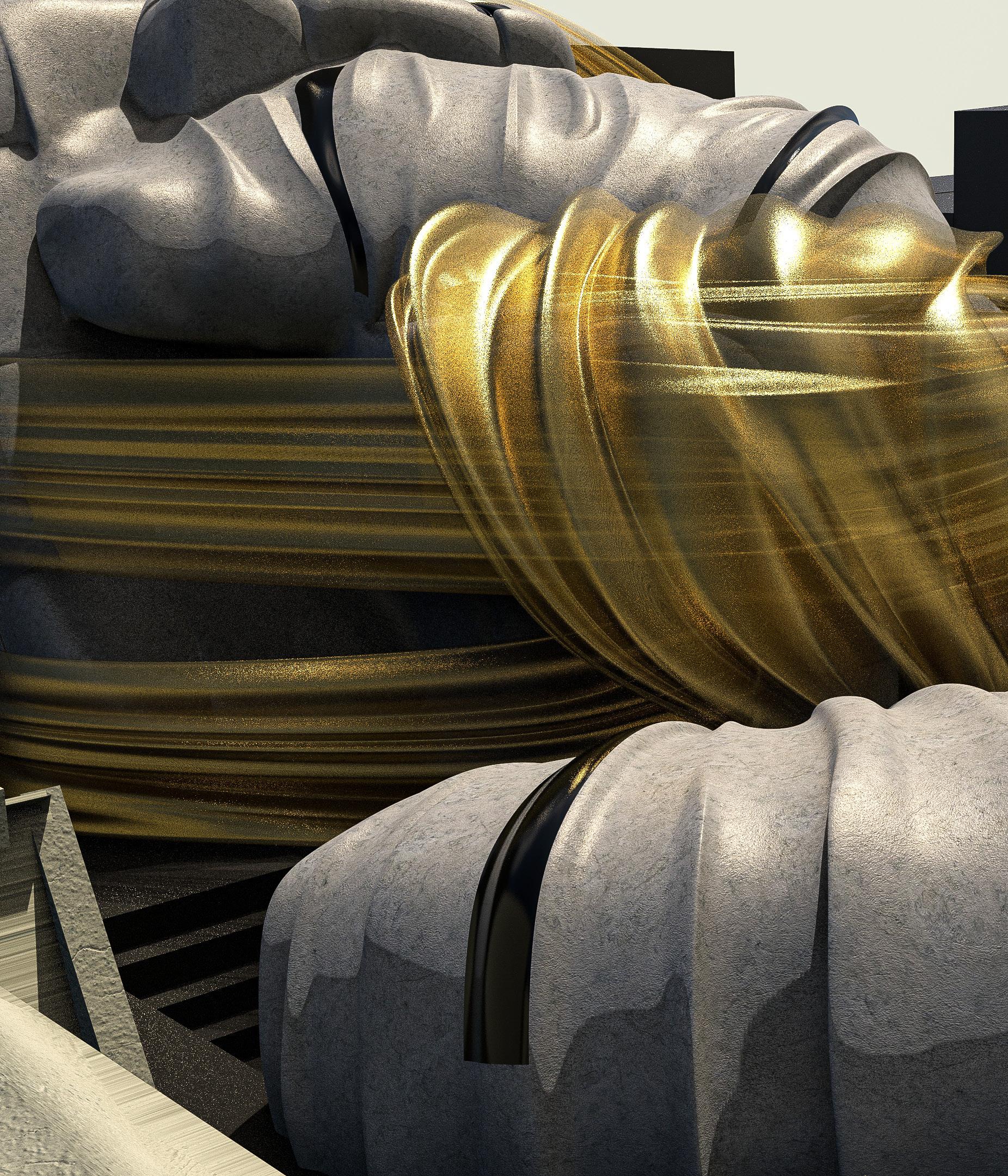
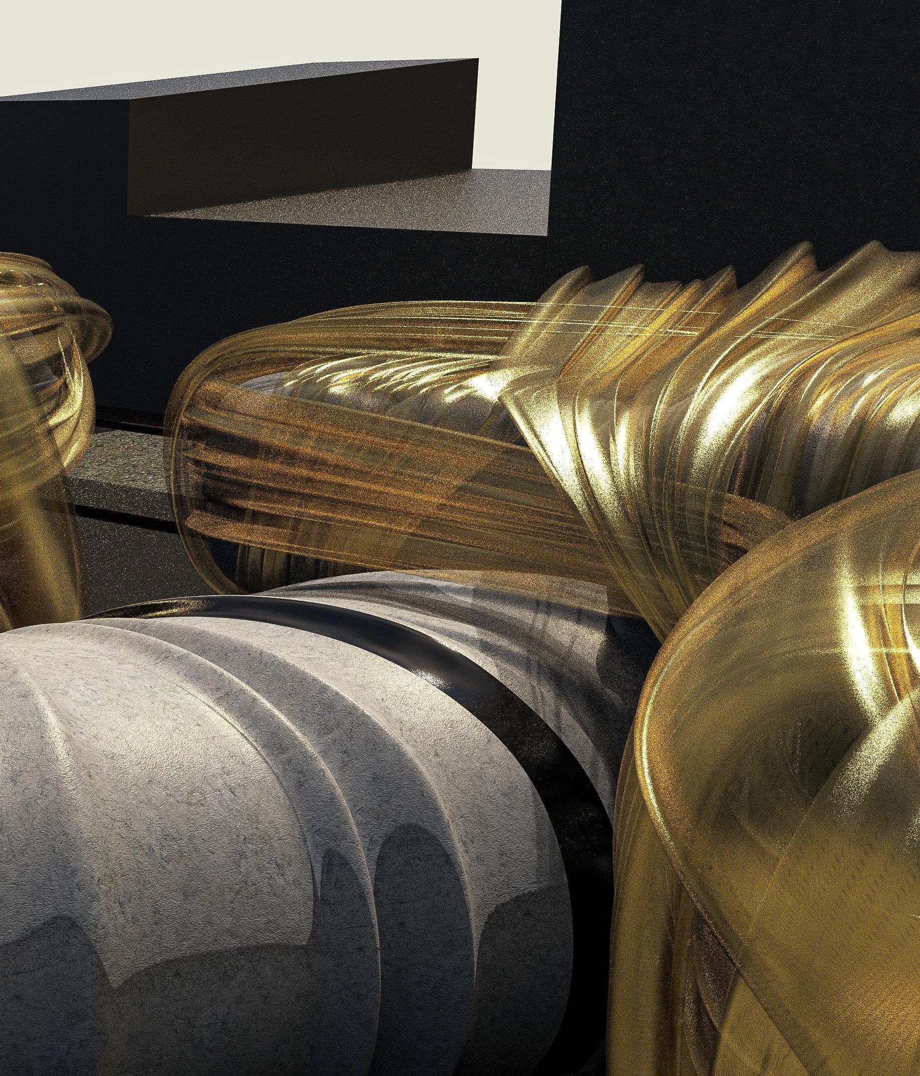
My chosen site is a school next to Candela’s Church of Our Lady of the Miraculous Medal (by Felix Candela) which consists of a continuous series of parabolic, concrete shells that forms the entire building, analogous to a singular continuous shroud that covers my hybrid model.
My project shares some qualities with Candela’s design whereas other moments present a point of departure. As opposed to the singular continuous shell of the church, my project consists of a number of cushioned masses which are stacked and shrouded by an exterior wrap creating a complex of multiple buildings with a degree
of independence from one Similar to the hybrid, the wrapped in various ways directions more akin to textile designs.
one another. the buildings are ways and Kawakubo’s

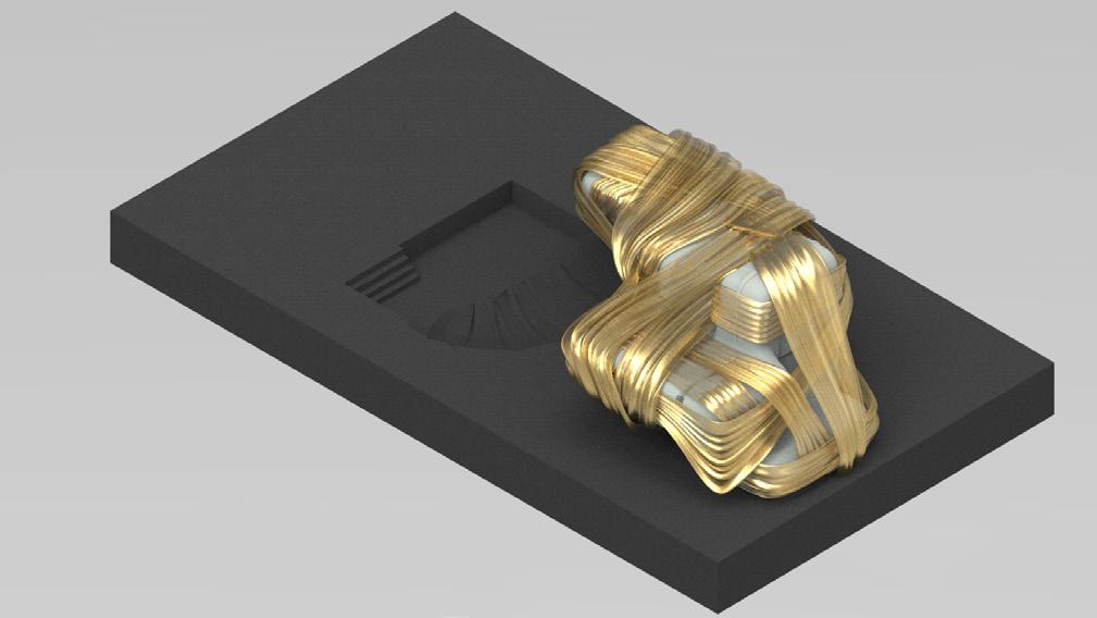
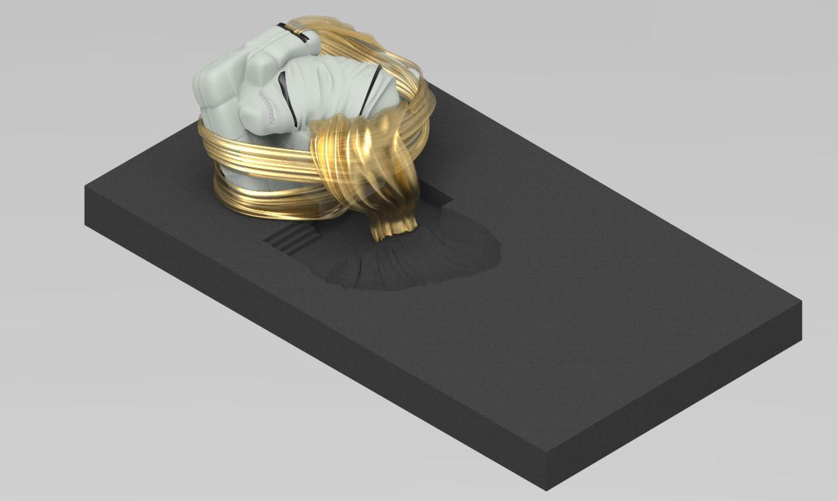
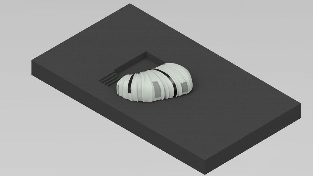

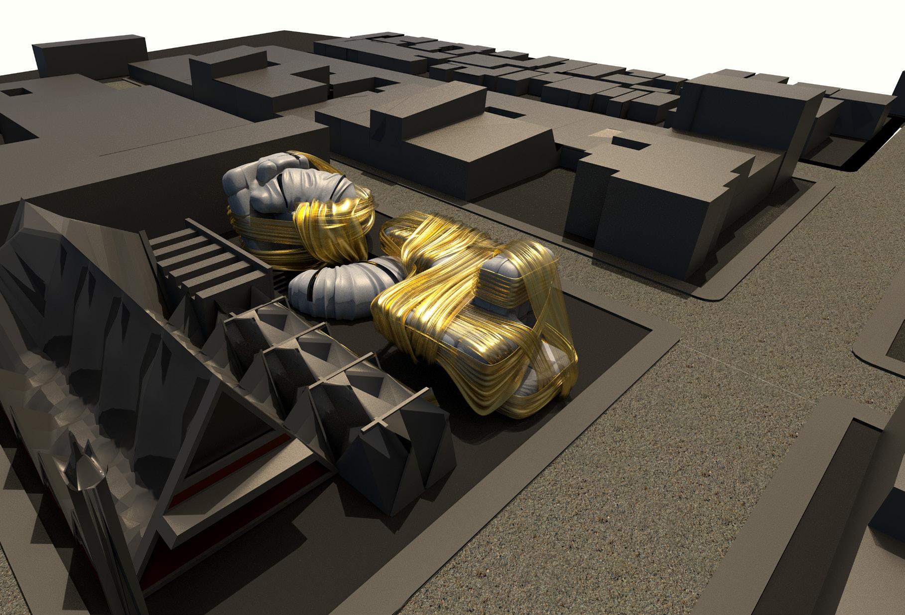
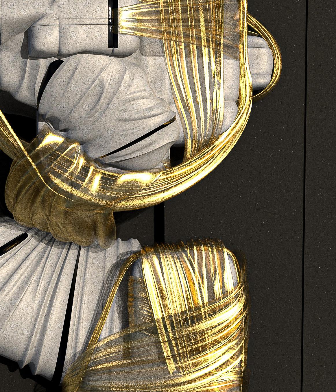
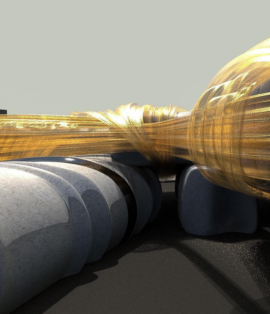
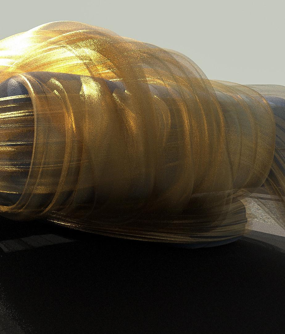
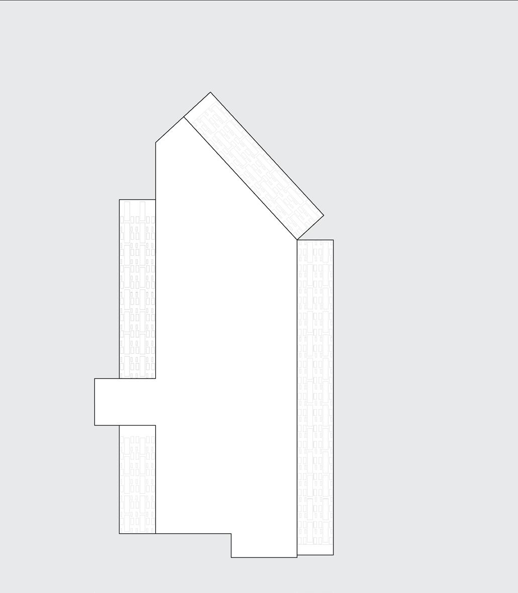
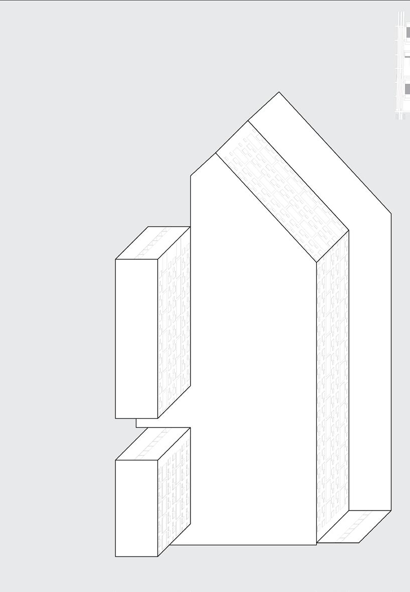
The massing is split into three chunks with varying degrees of wrapping. The front has the heaviest and tightest wrap. At the back, the wrap has a looser quality, while the auditorium in the middle is a hybrid whose facade takes on the quality of the wrapping, a mediation between the shrouded and unshrouded
condition.
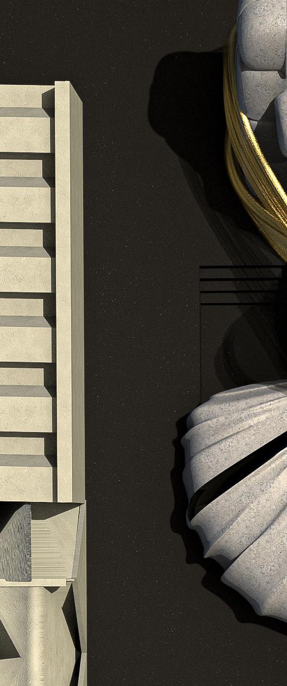
There is no separating wall between the church and the school. They are part of the same plot of land, which creates more openings and leads to an interplay between the church and the school, leading to interesting moments.
Here, you can see the tight and loose wrapping quality of the fabric imprinting onto the ‘cushion’ as was the case in the hybrid model as well, while the mass itself is uncovered. This hybrid condition leads to a third ‘in between’ interpretation of this project.
The mass in the center is the auditorium, which connects both the other masses with each other visually. It lies within a slightly excavated part of the ground to create a multiple levels of the project. Visually it is nestled gently into the ground.

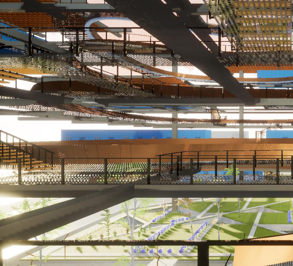
DS 1420
Thesis Advisor: Radically Augmenting housing in Faisalabad, Pakistan.
Marcelyn Gow
Graduate Thesis Project - M.Arch 2

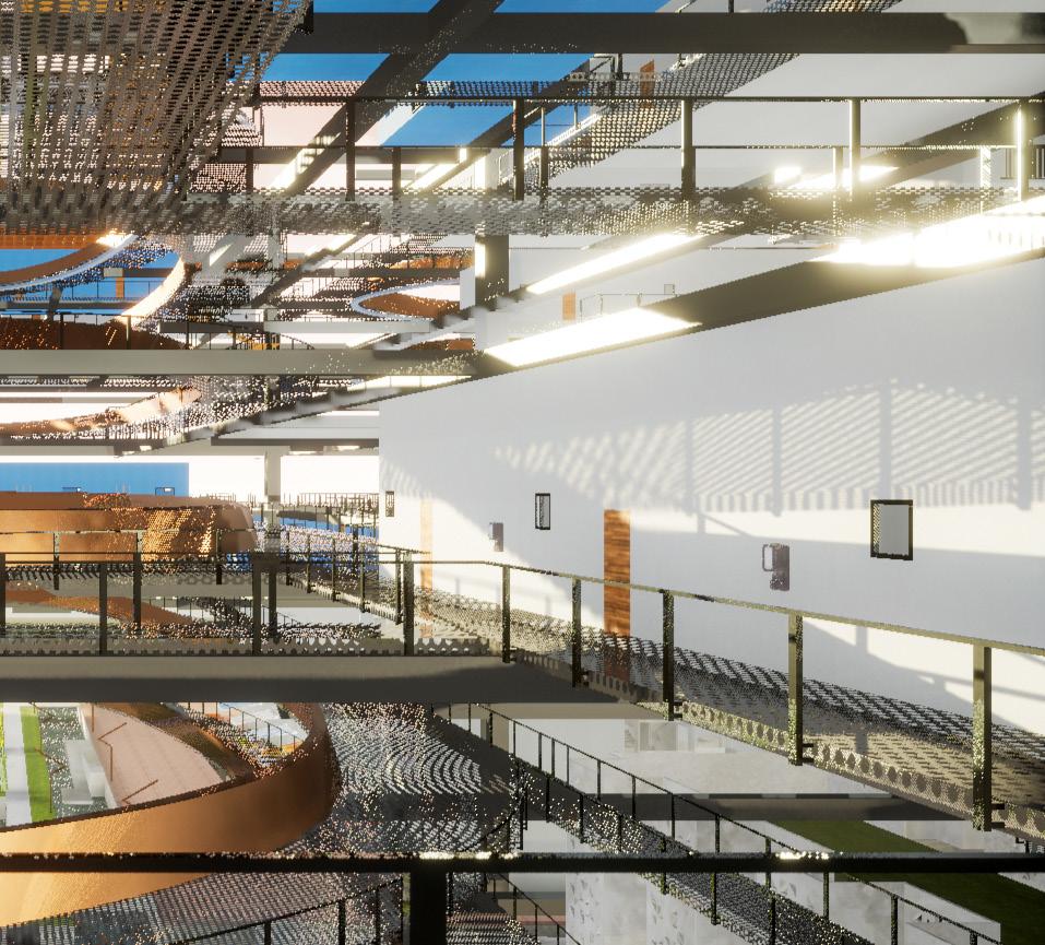
Pakistan is particularly vulnerable to the challenges posed by climate change, including both flooding and drought, in addition to the urban island heat effect.
Existing structures no longer adequately respond to user needs and the current ecological imperatives of the world,
neither can we afford to replace them wholesale.
My thesis proposes to address this dilemma by using an augmented, as opposed to an adaptive, approach to this problem, by retrofitting existing structures to customize them to suit the world we live in today.
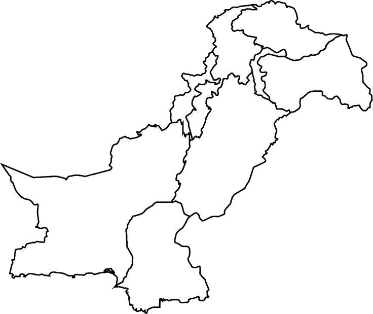
The climate in Pakistan is generally arid, characterized by hot summers and cool winters, and wide variations between extremes of temperature at given locations.
My proposal provides a solution to the opposing problems of increasingly hot summers and seasonal flooding.
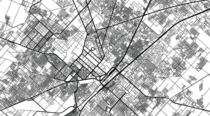
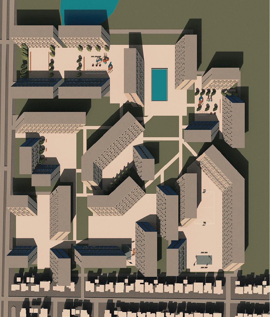
The map above shows the urban density map of the city. My site is located in an open area with potential for increasing density.

Existing Structure
The existing relatively open to a large green such a built
The site as has space in blocks and surroundings
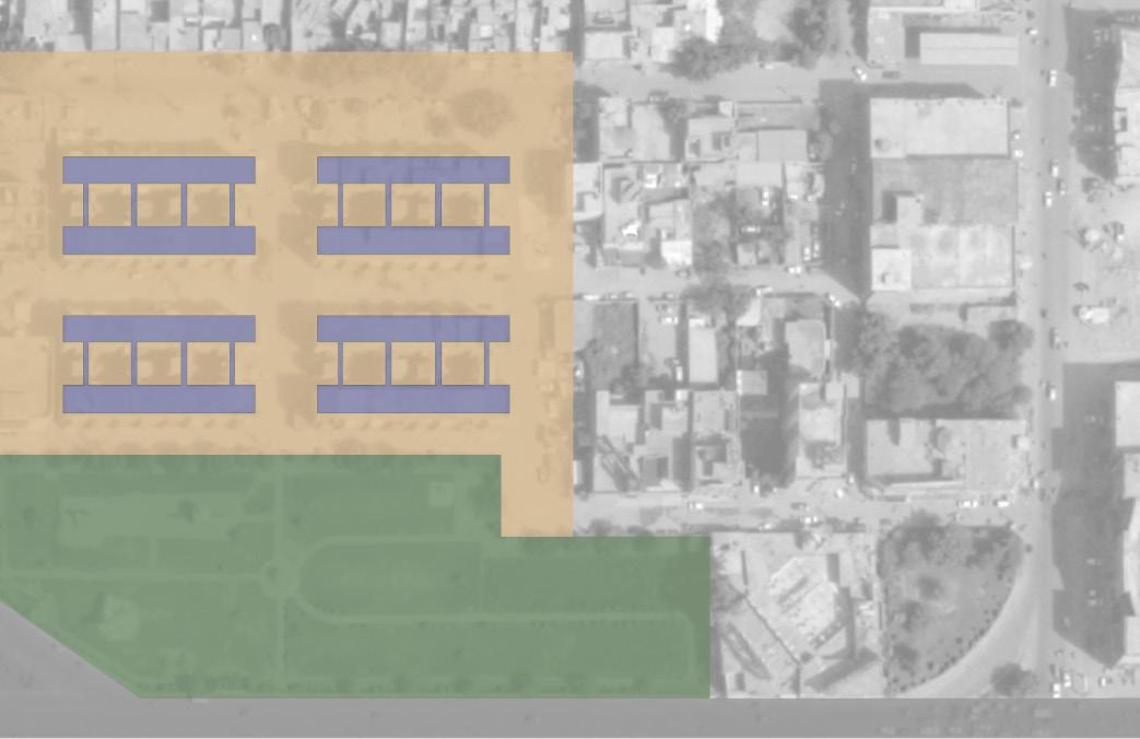
existing structures are situated in a open area, which is adjacent green space uncommon for built up area.
currently configured also in between the individual its immediate surroundings have become largely pedestrianized.
It is bound on 2 sides by a traffic artery. Furthermore, the site is situated near a canal which can be partly diverted through the complex to create opportunities for passive cooling as well as recreation.
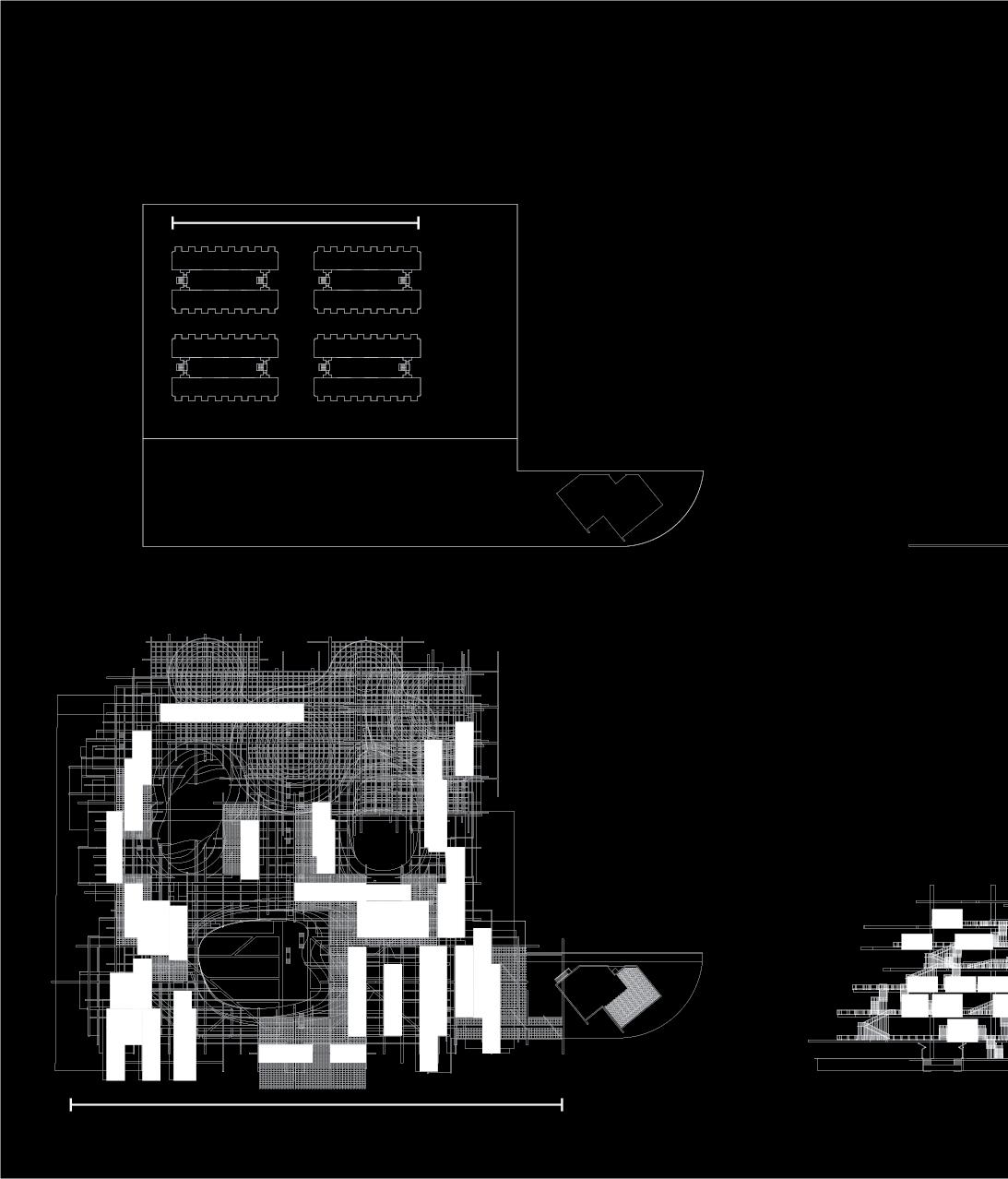
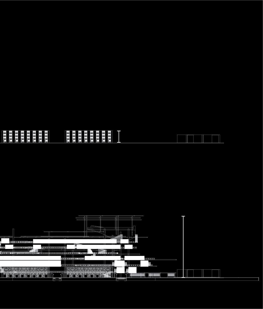
My augmented approach involves taking on the scale of a neighborhood rather than individual dwelling units.
The scale of the neighborhood allows my project to set an example on an urban scale of the way forward when it comes to addressing the fundamental realities of today in a water stressed, semi-arid region like Pakistan.
The third tier shows the trellis structure disrupted by three atrium spaces which act as light wells as well as public spaces for gathering and are connected by pathways in the cloud for circulation.
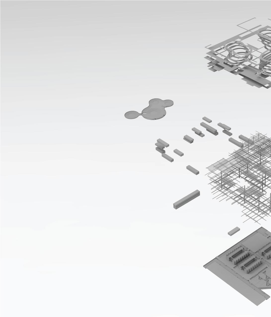
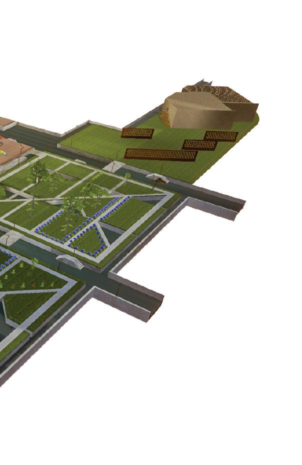
This 3 tiered diagram shows the logic of the shade cloud. The ground plane, which is the first tier, has been re-engineered to activate the public aspect of the proposal as well as become a sponge to absorb water during monsoon flooding.
New programming in the renovated original structure includes a school for residents of the Shade Cloud as well as a textile weaving unit, taking advantage of a skill already present in the city.
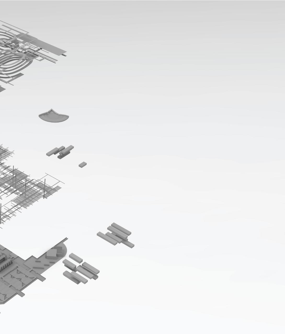
The second tier shows an 8 floors high trellis structure covering the area. The varying density of the trellis is key, from thick load bearing members, to lighter structural members acting as a connective tissue for the shade cloud, to shade providing elements of the cloud, helping to create micro climates.
Residential units are located inside the trellis structure. Private recreational areas for residents of the shade cloud are also plugged into the trellis, including a hanging garden as well as a theatre or auditorium space to form a vertical low rise mid density neighborhood arch-type.
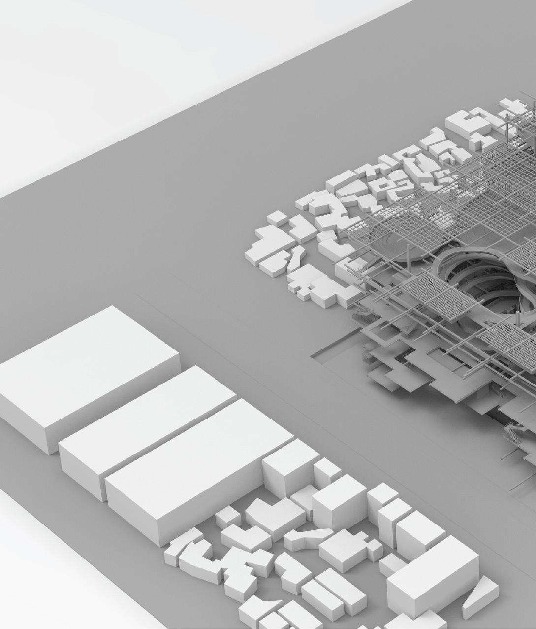
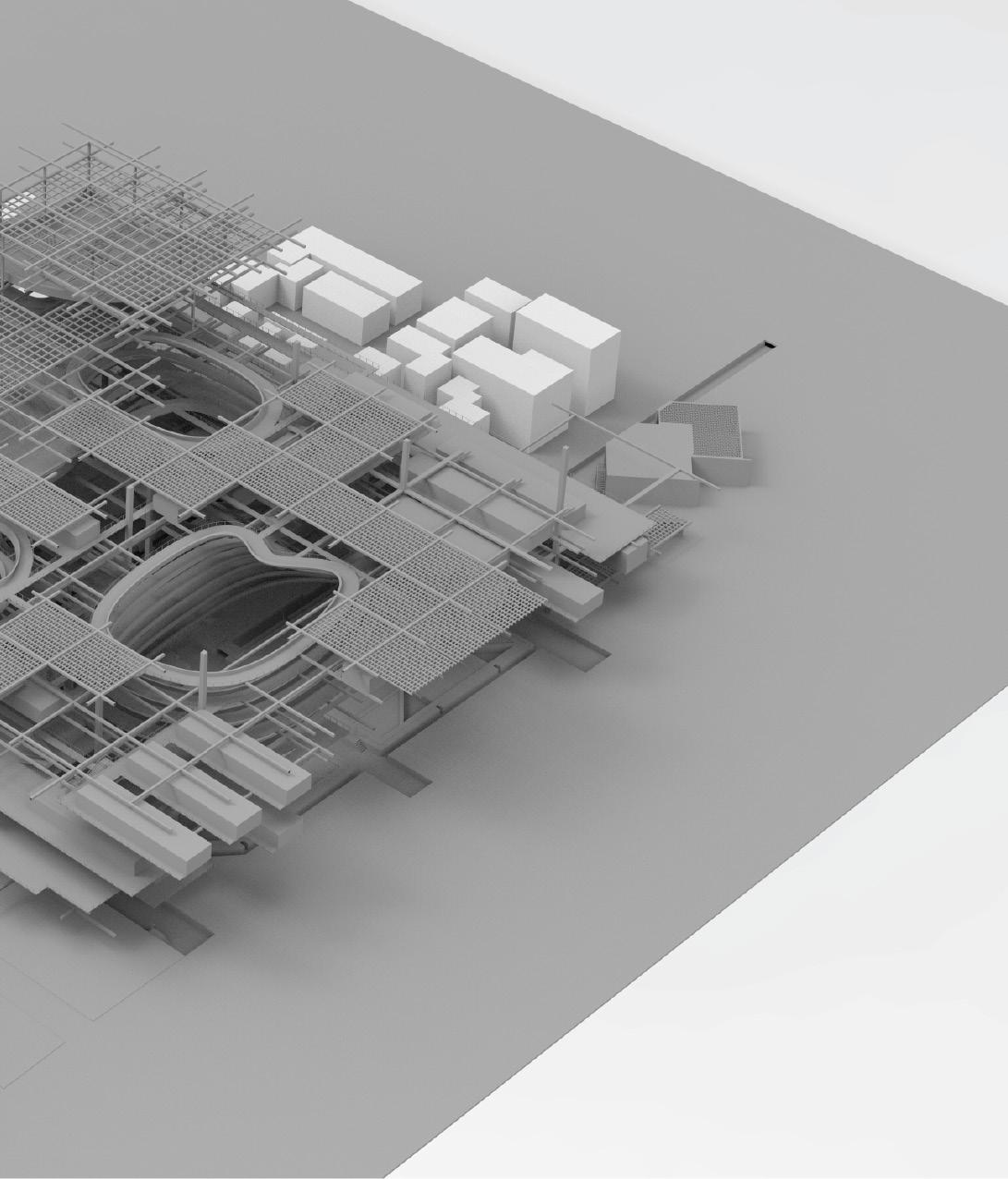
The ground floor can be seen here in isolation.
The diverted canal serves multiple purposes; primarily - in conjunction with the green space - to convert the area into a ‘sponge area’ capable of dealing with rising water during the monsoon floods, and secondarily to create recreational opportunities for the residents of the Shade Cloud, and forms part of a strategy to create micro climates.
The ground plane has been re-engineered keeping both the programmatic as well as ecological imperatives in mind. Athletics
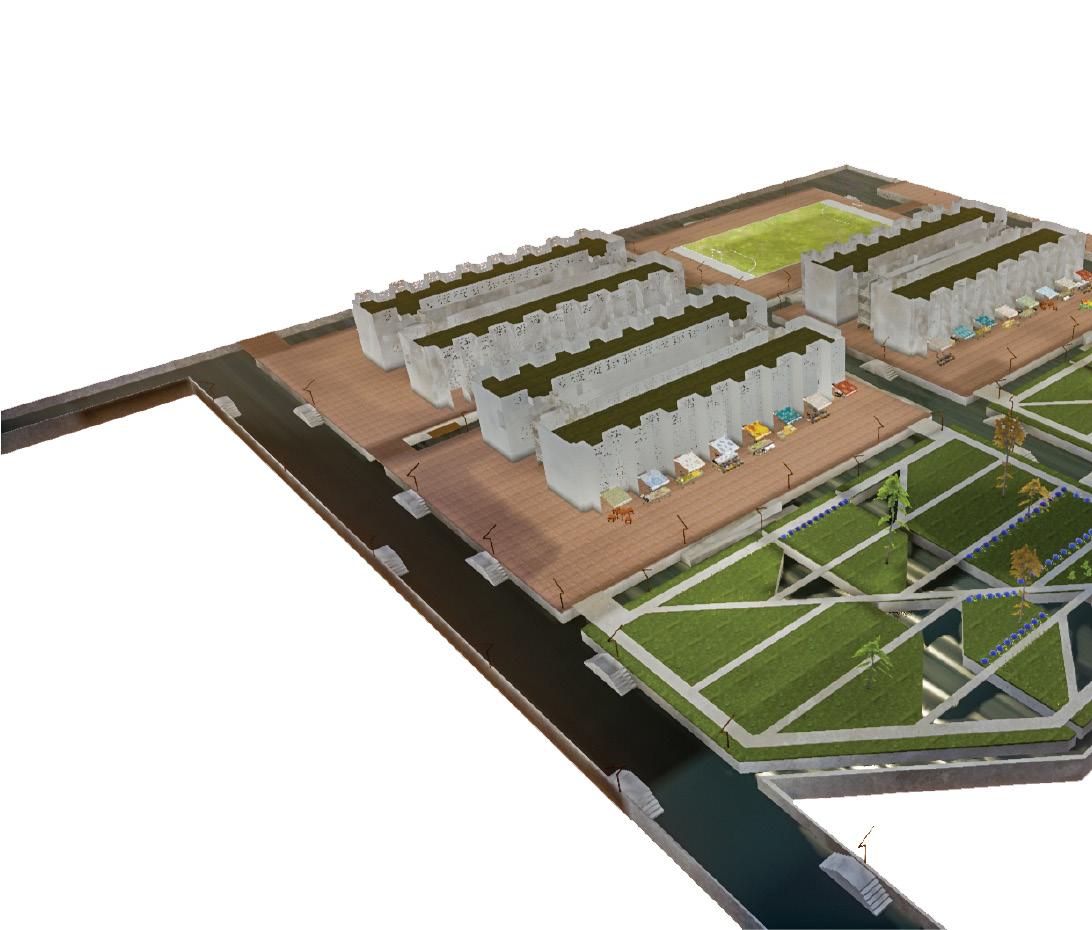
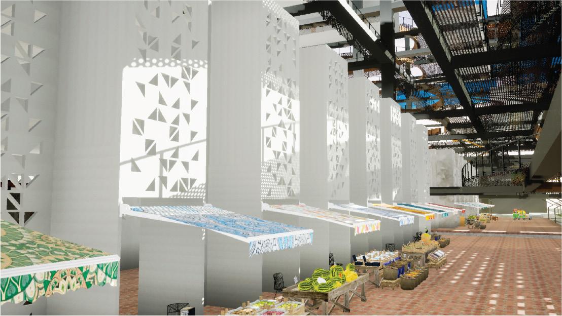
A jali, is the term for a perforated stone or latticed screen, used as a shading and ventilation device in the subcontinent.
It is used in a new porous facade opening up the original structure to serve as a new marketplace as part of a new programmatically active ground plane.
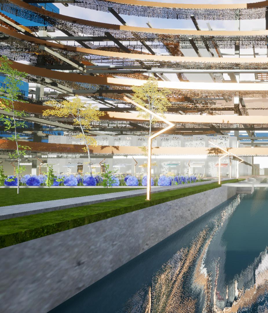
I approach the project through 3 scales, the first being the scale of the neighborhood which the proposal as a whole provides, with all facilities either within the structure or at walking distance.
Other than residential units, a theatre space or auditorium is integrated as a part of the trellis structure.
The second scale is the dwelling units themselves. There are multiple formats of units available to cater to various needs. The units are well furnished and are also located to take advantage of views from elevated vantage points with balconies and generous windows.
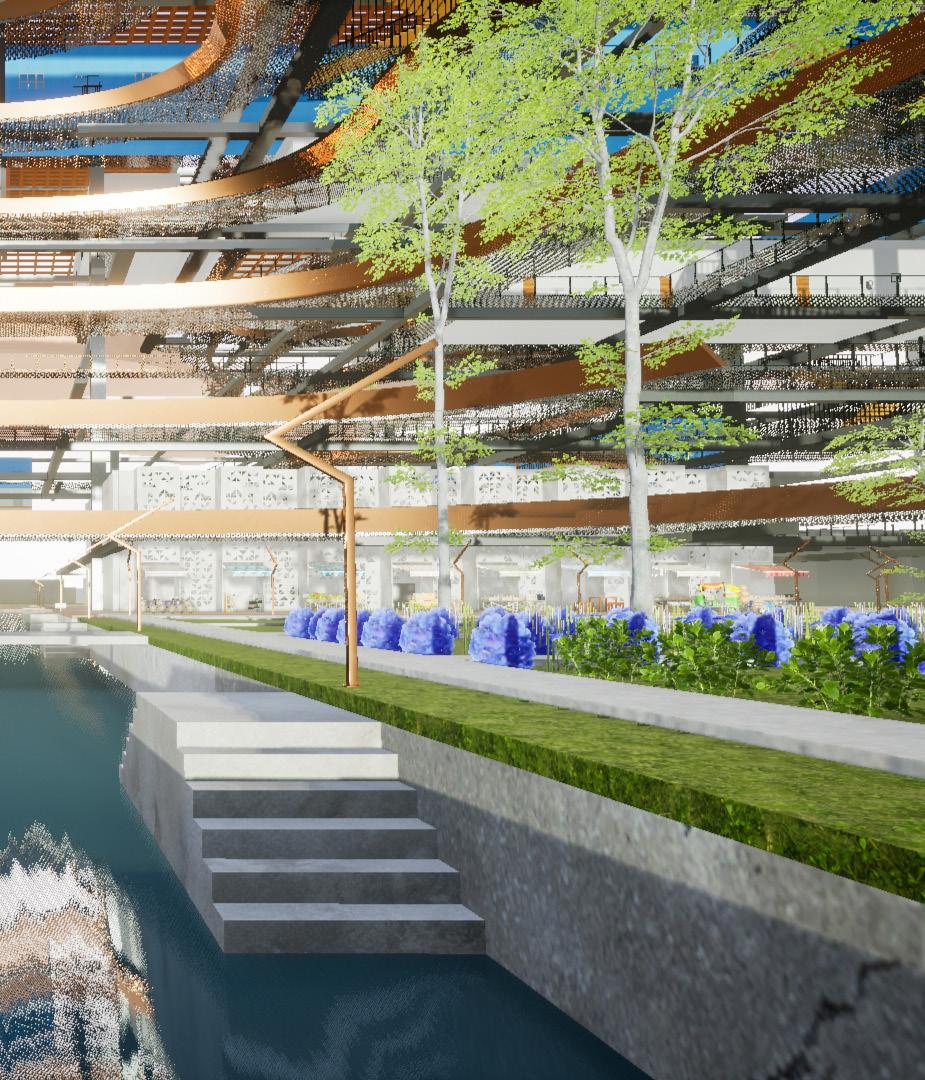
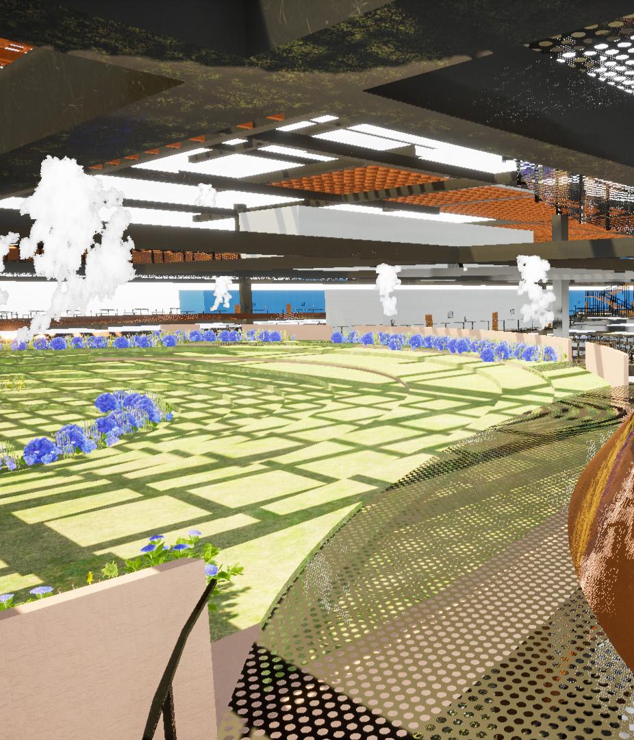
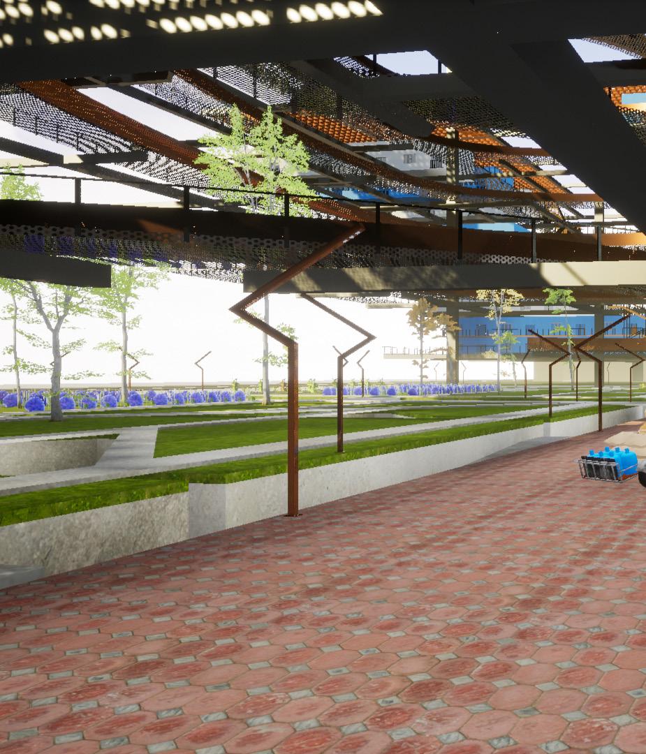
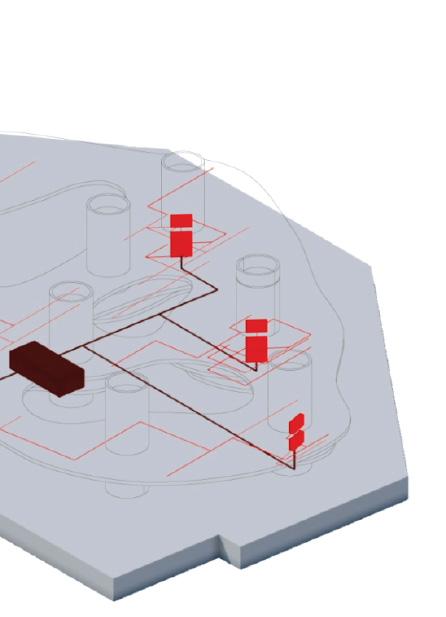
The main outdoor community space is a suspended garden within the trellis, provided with generous shading as well as cooling through a mist mechanism drawing water from the diverted canal below, creating a micro-climate.
Other platform spaces have also been provided which are free to be used as desired by the residents.
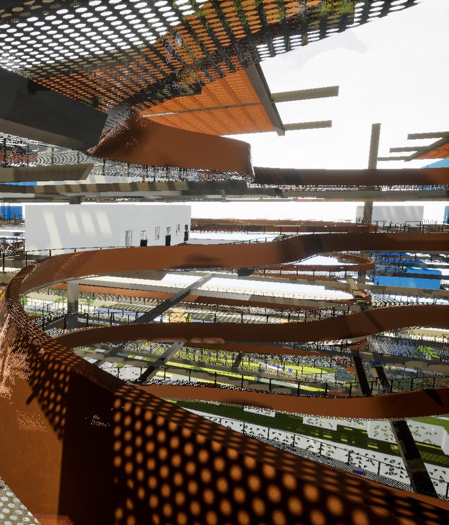
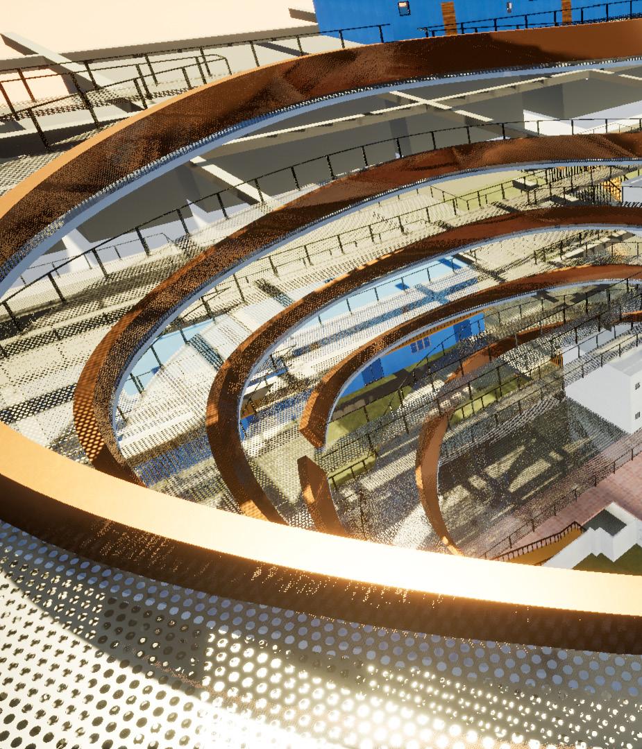
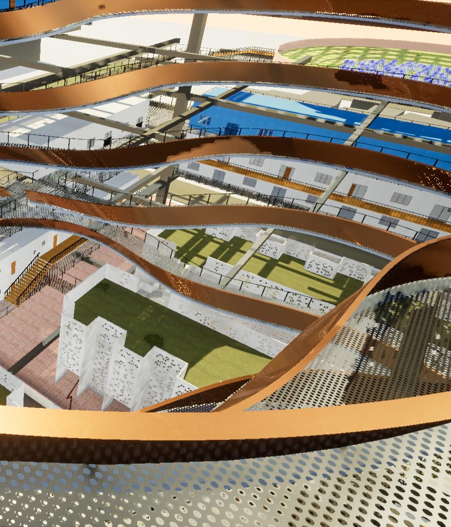
The school and textile weaving unit are located inside the renovated existing structures whose facade has been opened up based on contemporary jali patterns.
Traditional taxis, known as rickshaws are driven by a number of people in the Shade Cloud, so space for their parking has also been allocated.
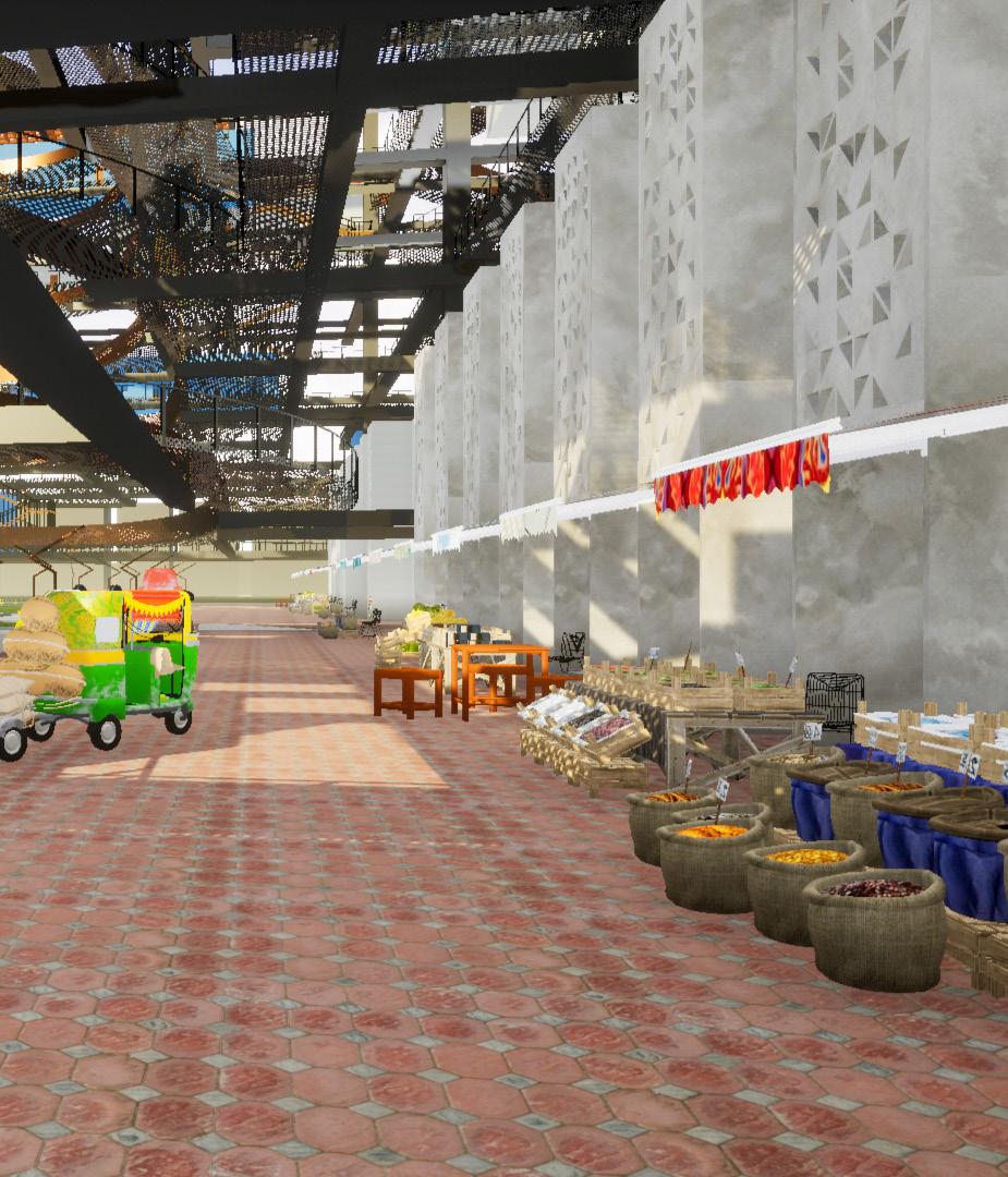
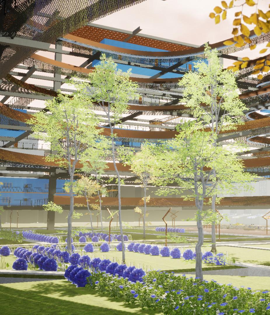
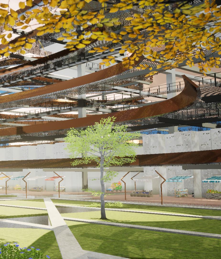
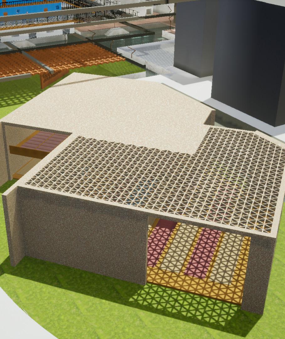
The third scale is the details such as the jali patterns spread throughout the site on various scales, providing aesthetic as well as shading strategies. Together with mist generated from the canal below, it forms a passive cooling strategy, which is important to the ecological imperatives of this project as they help to create micro climates within the structure.
The jali pattern has been incorporated into the renovated mosque, seen here, an important element of any neighborhood in Pakistan.
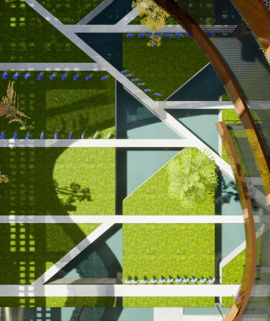
The jali pattern was also used as a departure point for the public garden, on the right, designed to have pools of water elements instead of just a linear canal network. These areas also form spaces of congregation.
DS 1201
Instructor:
Damjan Jovanovic
Hsiang Wang
Partner: 1st Year Design Studio
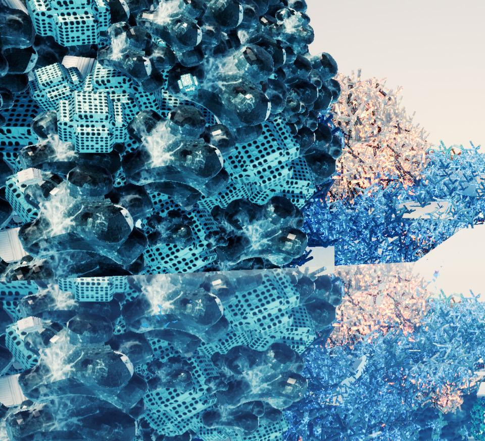
Digital Catalyst reflects on value in the post-digital era, where the museum architecture has become the catalyst for digital content. Museums and artifacts are regarded as objects struggling in the value system. While we focus on communicating with the masses, the boundaries between
popular and elite culture become blurry. The museum plays a double-side role as both encyclopedia and content farm. It could be superficially transparent, democratic, subtle and natural, but substantially institutionalized, centralized, explicit, and artificial.
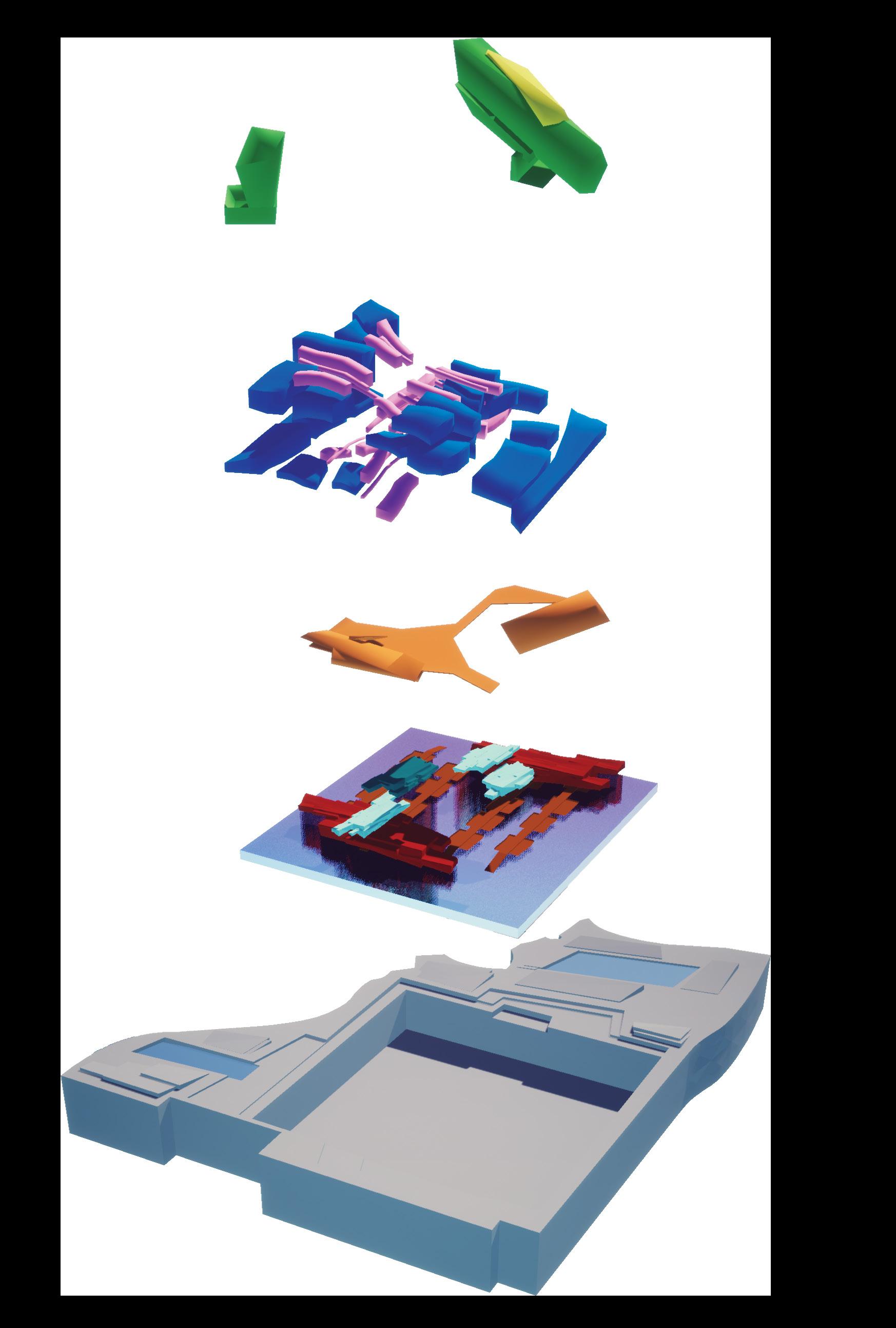

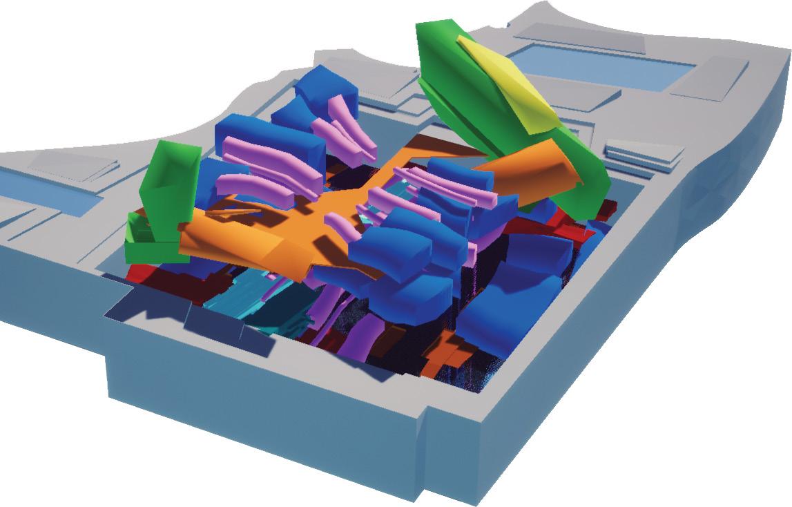
Office Gallery
Storage/Archive Education
Our project’s departure point was various massing models heavily influenced by design projects by OMA, and took its inspiration from collectives such as archizoom.
Special attention was paid to the grid both as an organizing, and disrupting element.
Experience Space Gallery
Circulation/Flex space
Theatre
Restaurant
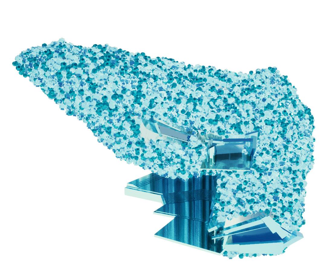
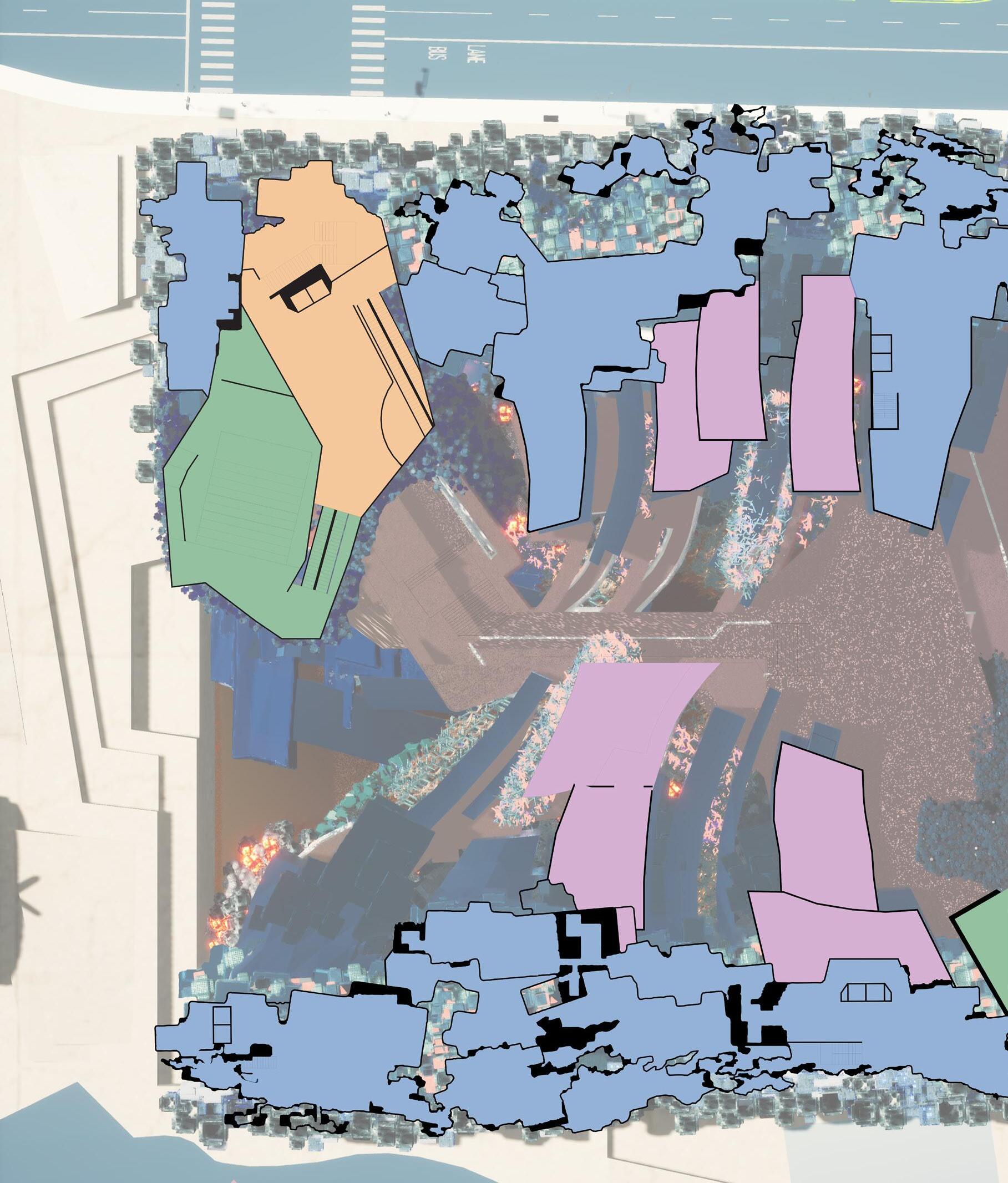
The project requirements dictated that we design for three main elements, storage space, display space and nature space. Our design is one with emphasis on plan, which integrates all the programs present in the project.
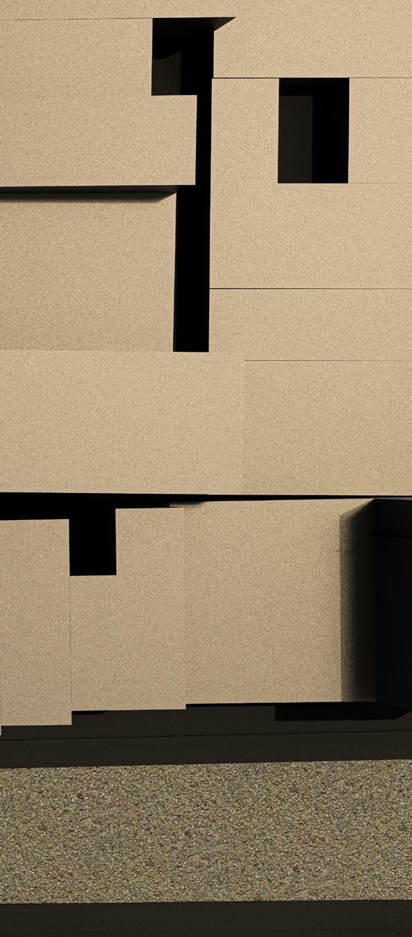
The planar base geometry was subsequently painted over with very fine aggregate.
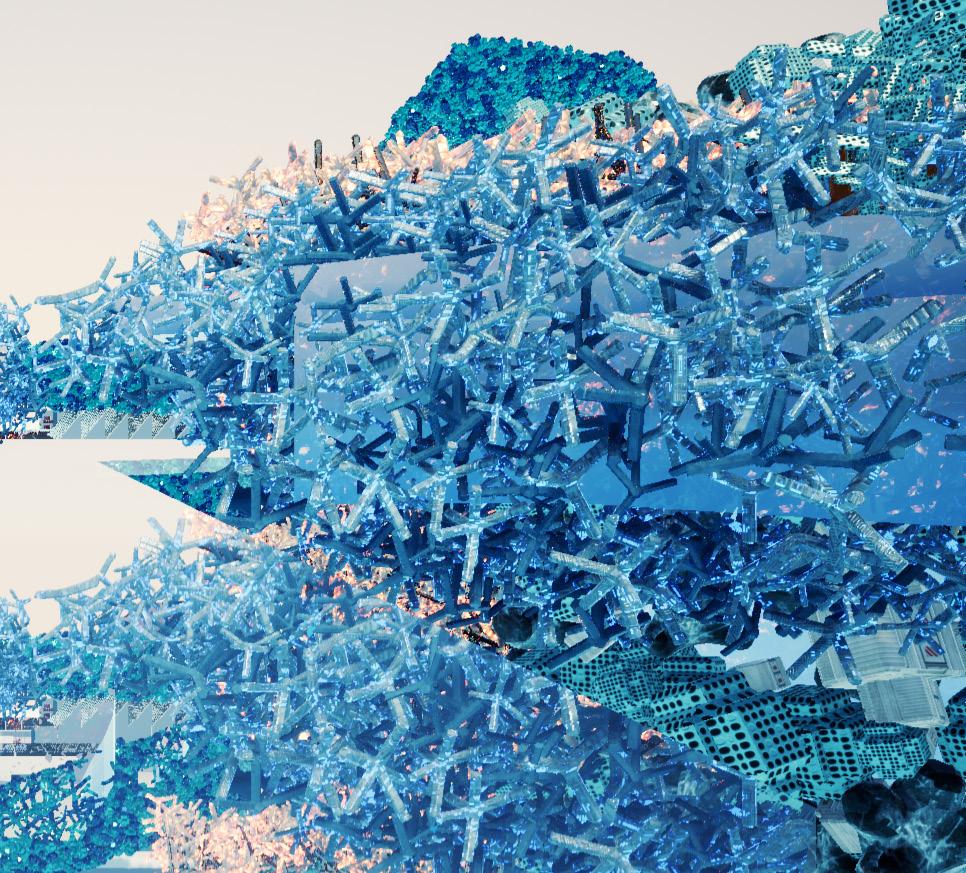
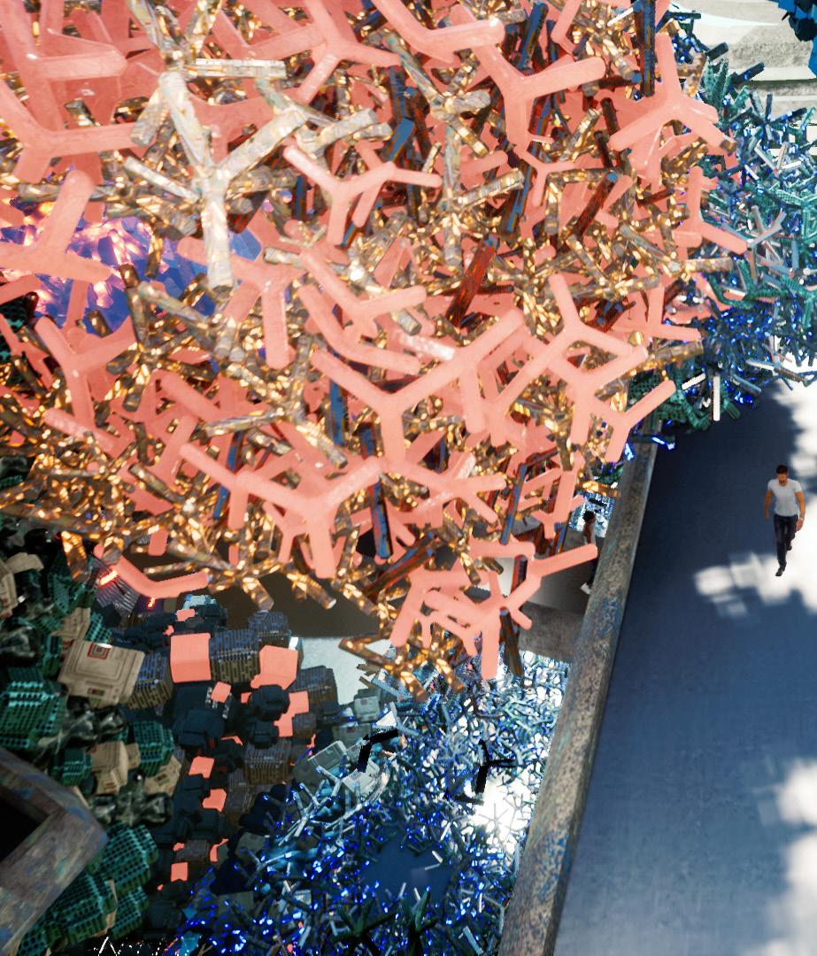
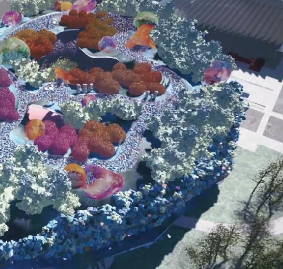
This aggregate was not meant to be simply a facade but was also to be operationalised at various scales, from as small as something you could hold in your hand to as large as an architectural space to be inhabited.
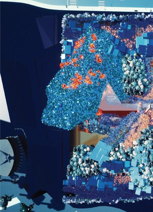
The aggregate is a mix of the digital and physical, and the infinite intersection of the base geometry with the aggregate at various scales, in both digital and physical form, became the generating force for creating the architectural experience in this project.
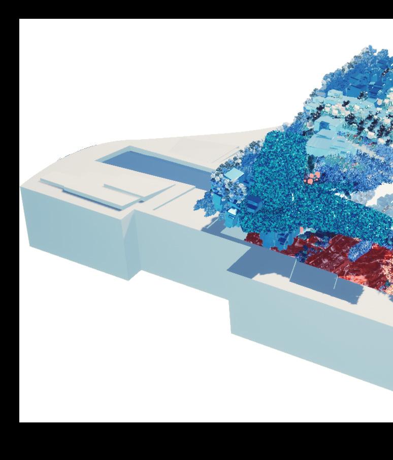
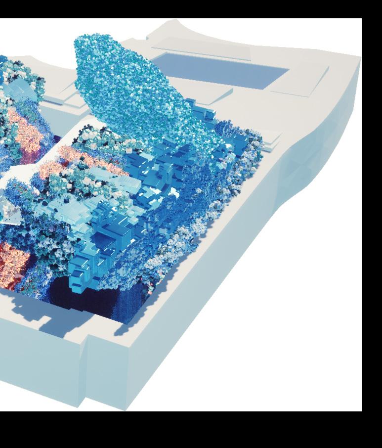
The main theatre stands out due to its relatively vertical orientation and conventional plan, making it the focal point of the project aesthetically. The entrance of the museum is also from the main plaza connected to the theatre.
The bridge is connected to the second floor exit of the theatre which is where traffic gets distributed to other parts of the museum.
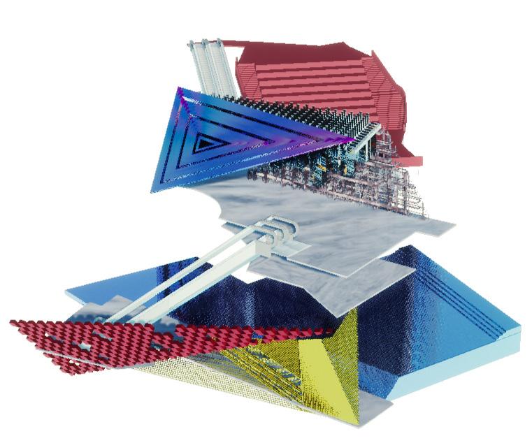
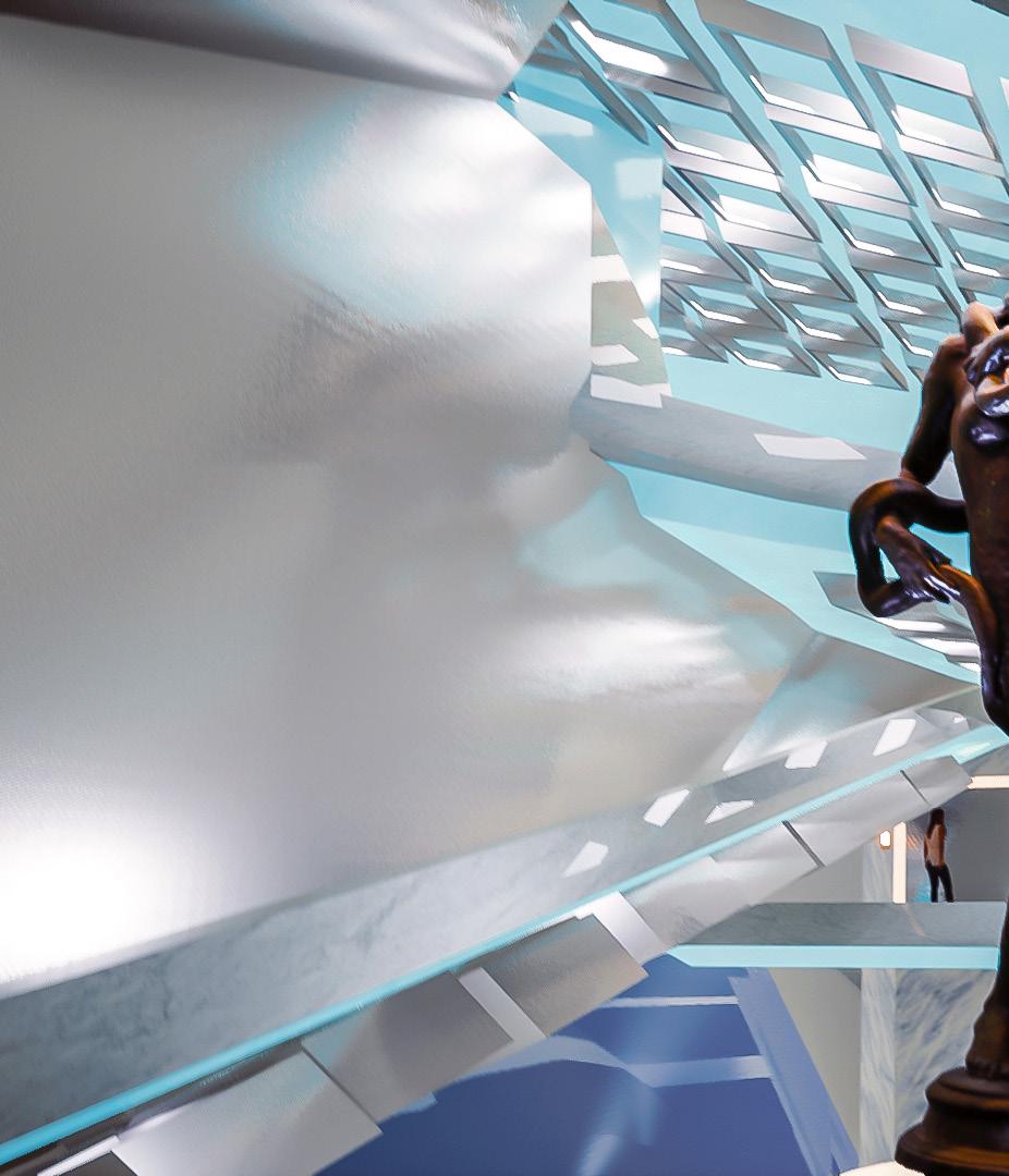
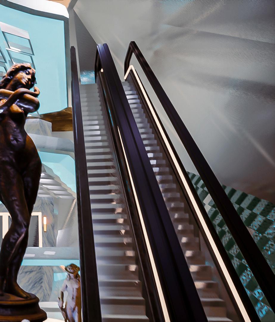
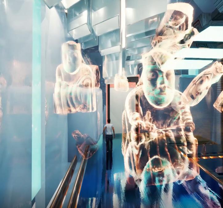
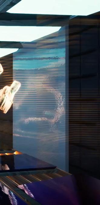
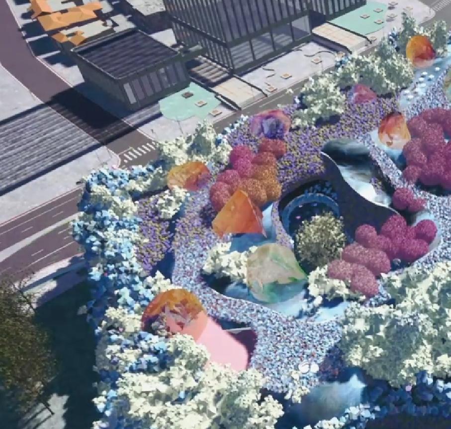
The tubular forms are the experience spaces, which liberate items in storage by turning them into digital projections.
The digital projection of dynamic aggregates along with the projection of artifacts provides a great backdrop for your preferred social media platform.
These holograms also play a role as pop up advertisements, showing highlights of the week. If the holograms make you want to take the next step, those interested in authentic artifacts could eventually follow the tunnel to the display space.
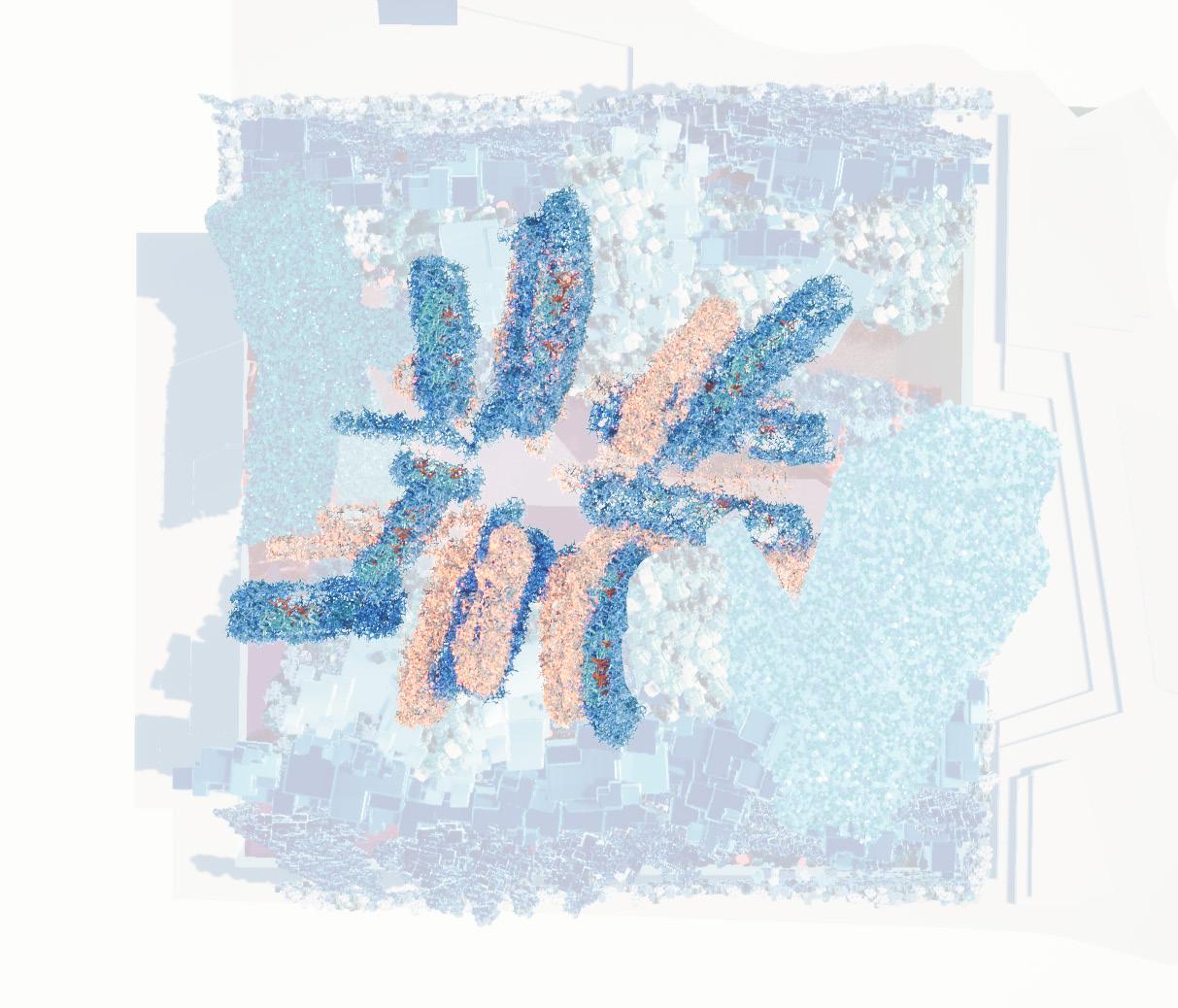
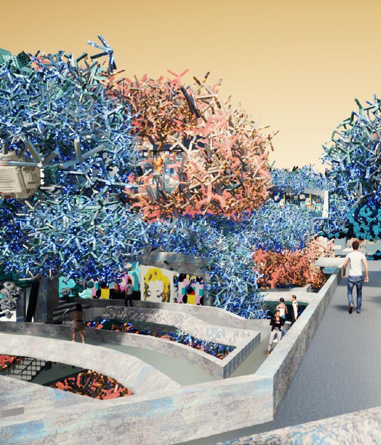
The non-hierarchy of the museum is defined by the bridge which connects all the separate galleries together. The digital aggregate also forms nature of a synthetic kind. A journey across the bridge becomes a walk through a futuristic topiary.
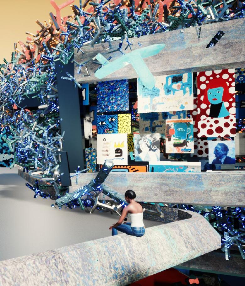
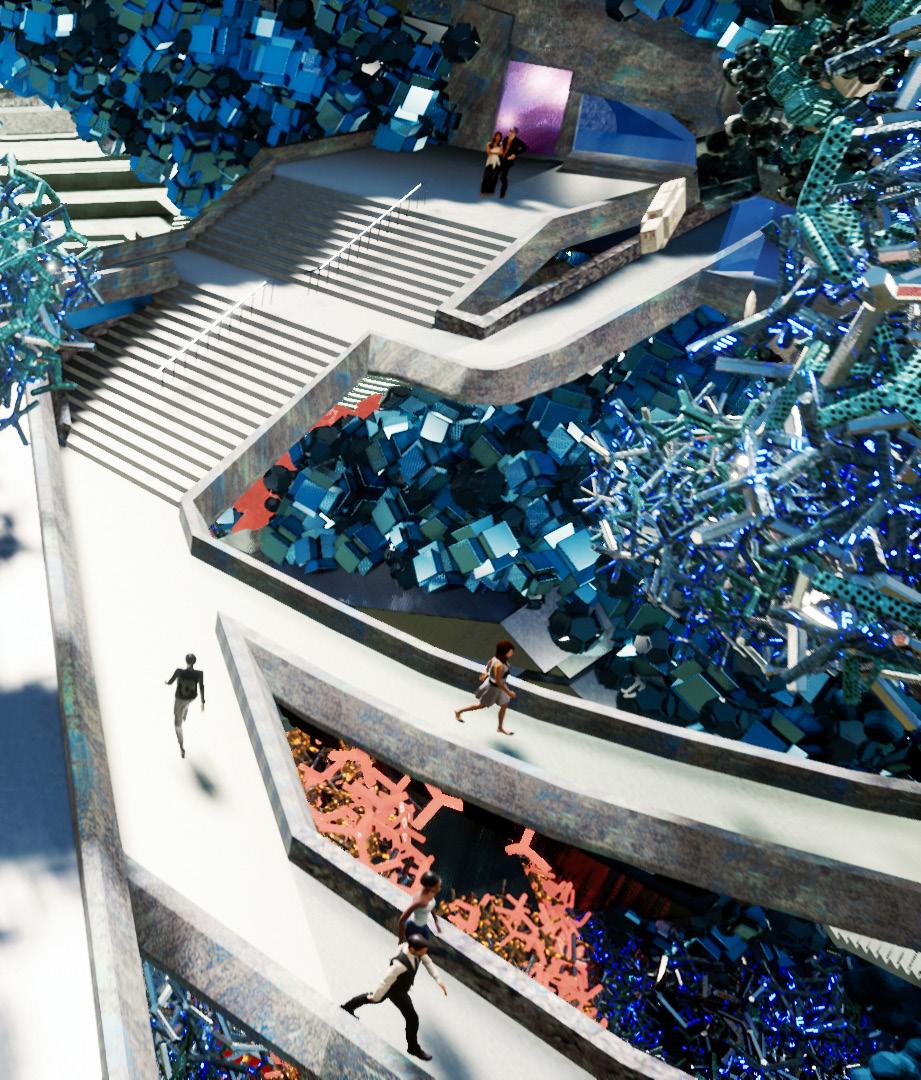
The small theatre diagonally opposite from the main theatre forms an informal environment and is programatically flexible. It also offers a viewing platform at the top, which is the highest point of the project, allowing sweeping views across the museum and also the city.
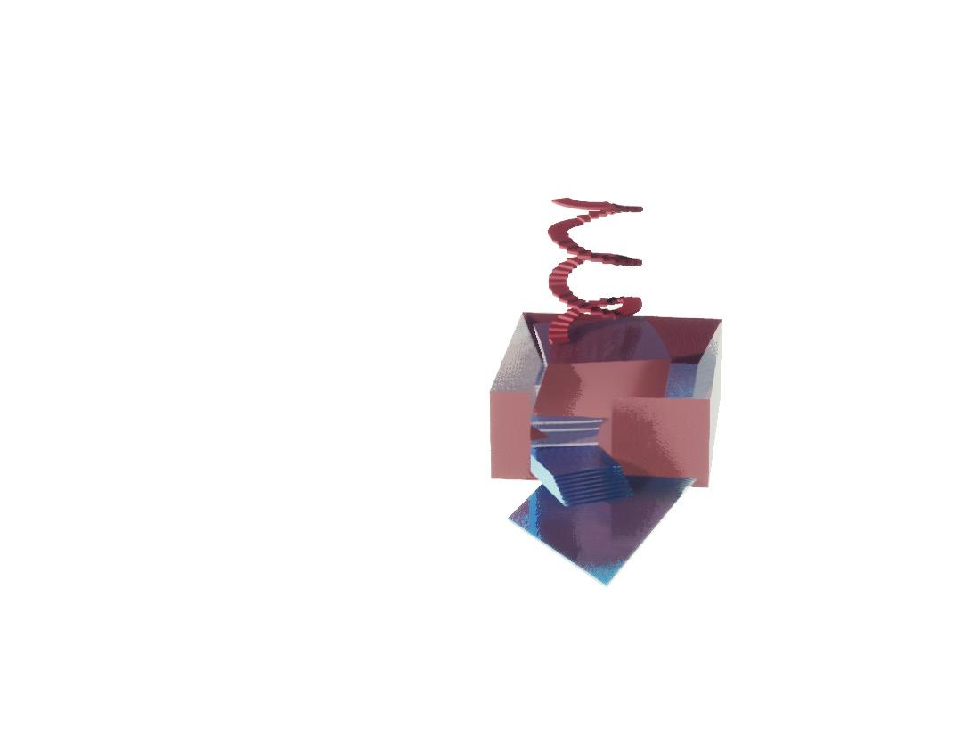
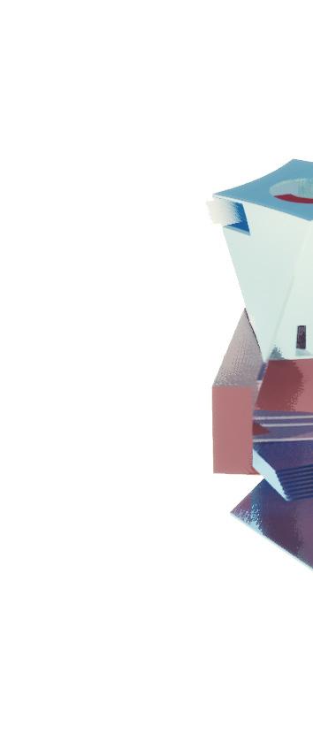
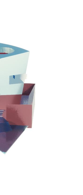
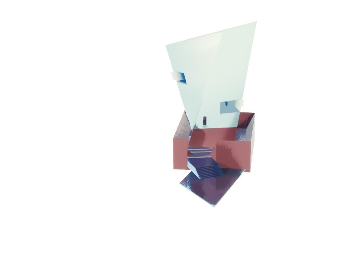
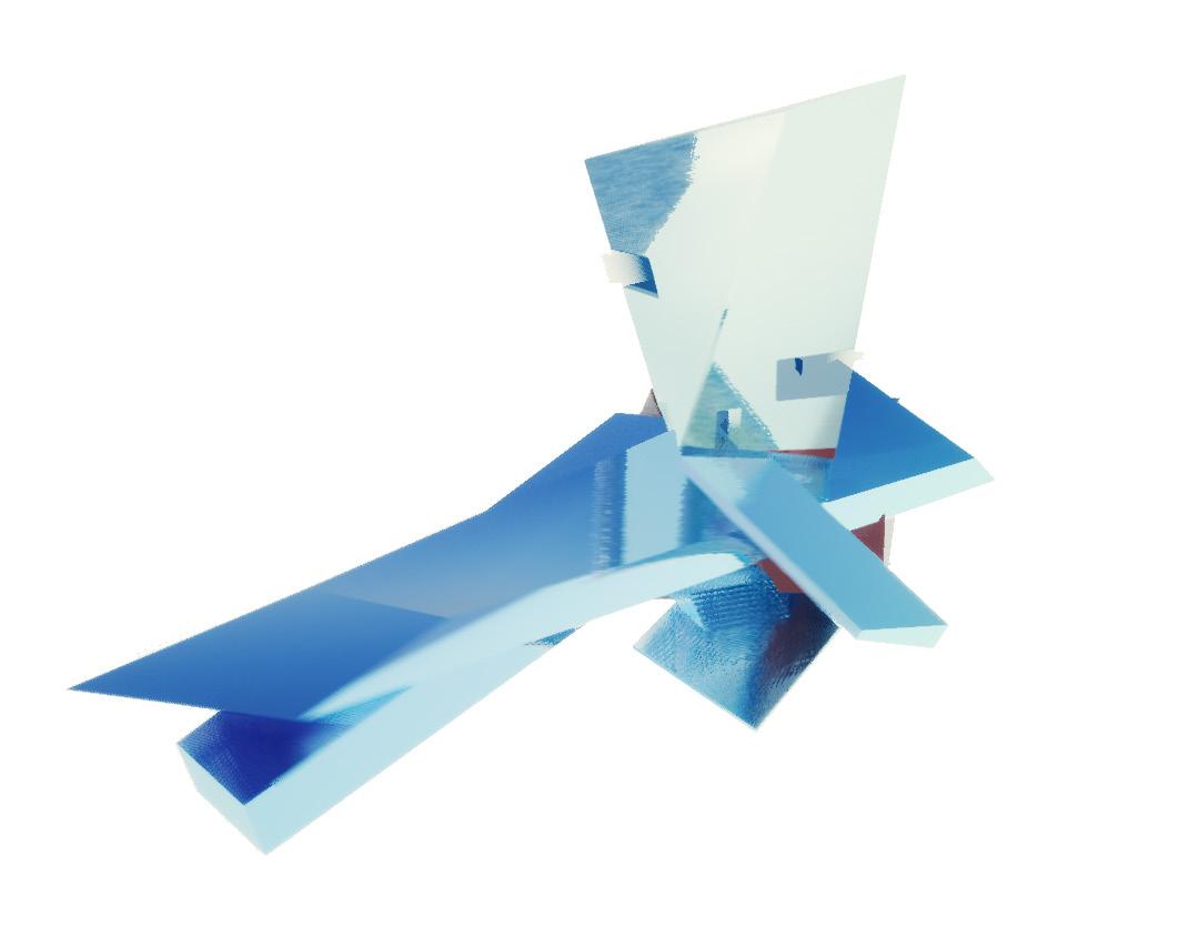
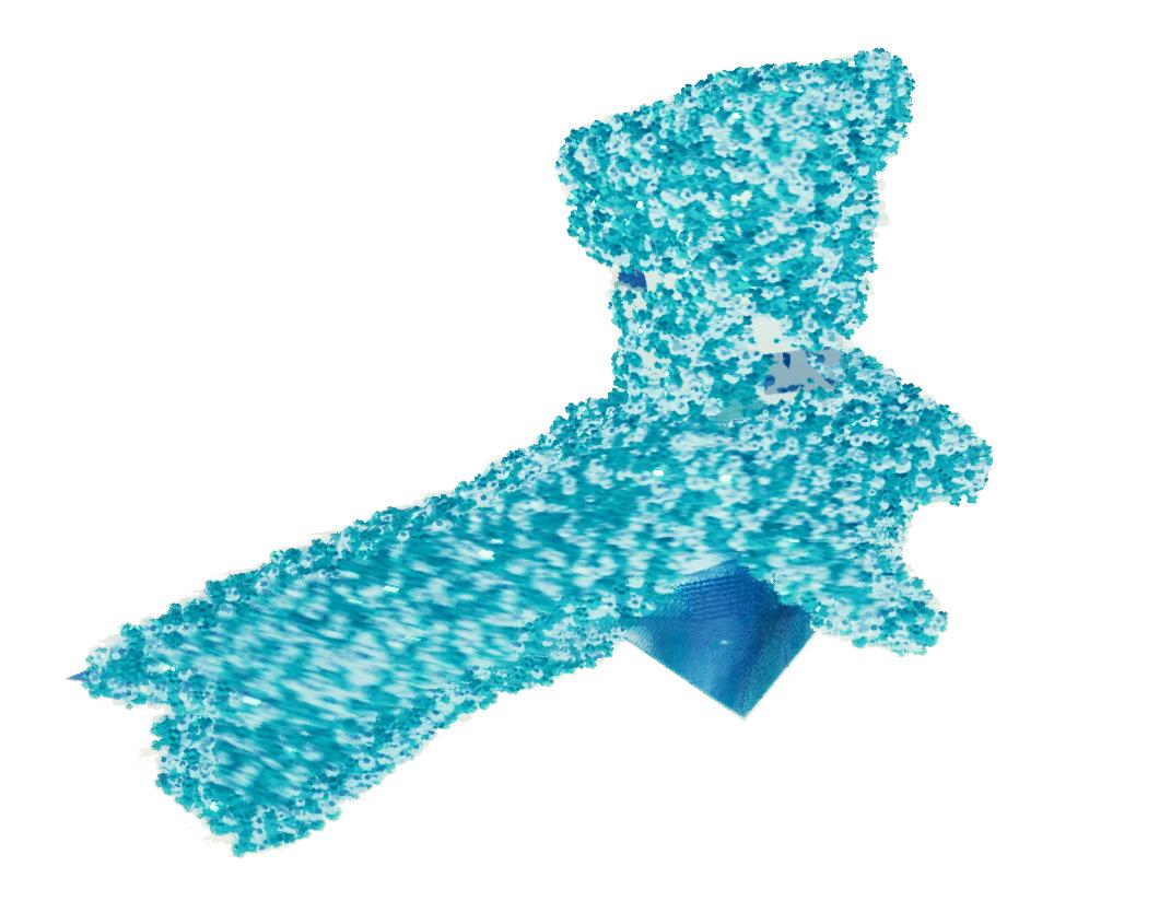

The aggregate matter is operationalized through increasing it in scale and cutting through to make gallery spaces.
The infinite intersection of the facade aggregate and scaled up inhabitable aggregate make for unconventional spaces which take on another worldly quality due to both the shape and surface treatment of the aggregate.
Lifting the project over an excavated basement space for nature also removes it from its immediate urban context, which suits the world building aims of this project.
In a role reversal, it is the conventional parts of this project that form the disruptive elements.
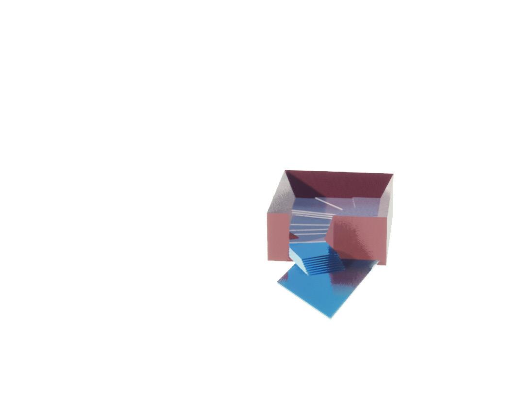
A solid void element is also introduced in the interior, which along with differing levels and unique form, break the monotony of the gallery archtype.
Experience Space
Gallery
Circulation/Flex space
Theatre
Abstractions of War
DS 5000
Instructor:
Anna Neimark
2nd Year Advanced Vertical Studio
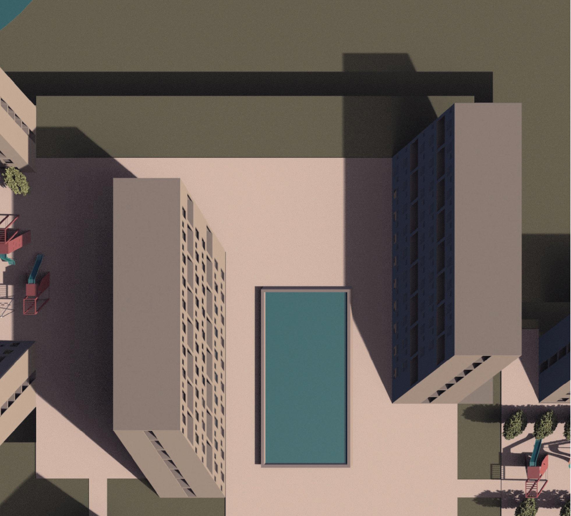
This studio analyzes fortifications in the American landscape from archaeological surveys and engineering drawings. After extracting their formal logic, these military structures will serve as formworks for new design concerns: against the prevalence of private development, we will
project new approaches to urban block design and collective living.
Part II brings the abstract forms developed through the students’ analytical studies into the urban fabric of Los Angeles.
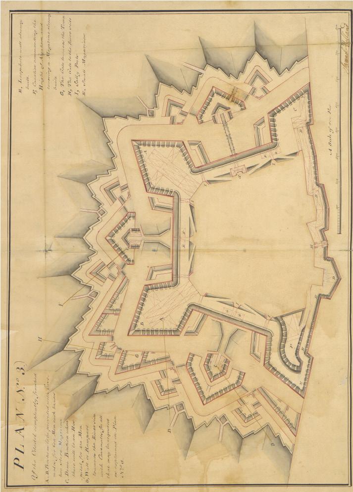

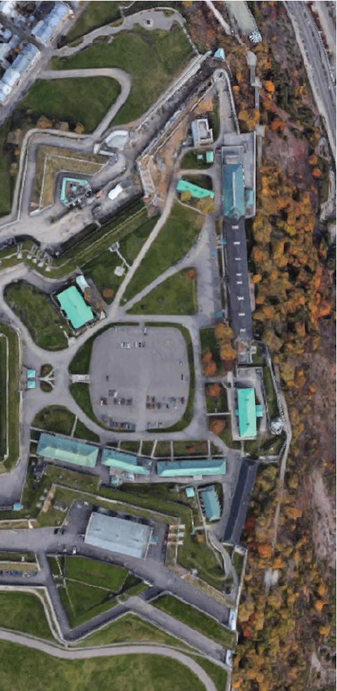
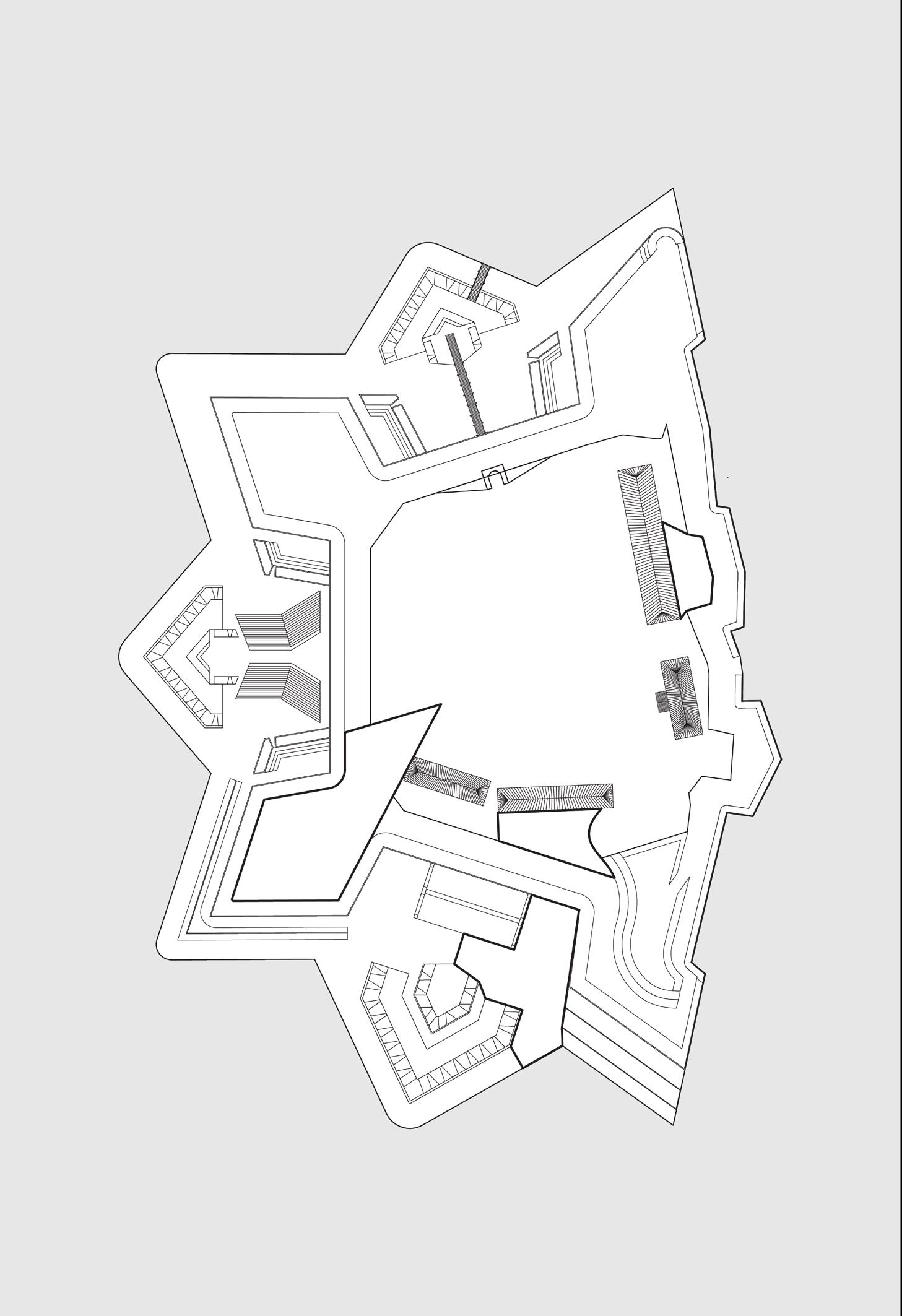
The fort I analyzed was the Citadel in Quebec. The construction of the fort started in 1830, but plans for it were drawn up much earlier, this drawing of the idealized version of the fort is from 1757.
The cost involved ensured that the fort wasn’t actually built until much later. The built form itself departs from the idealized version as well.
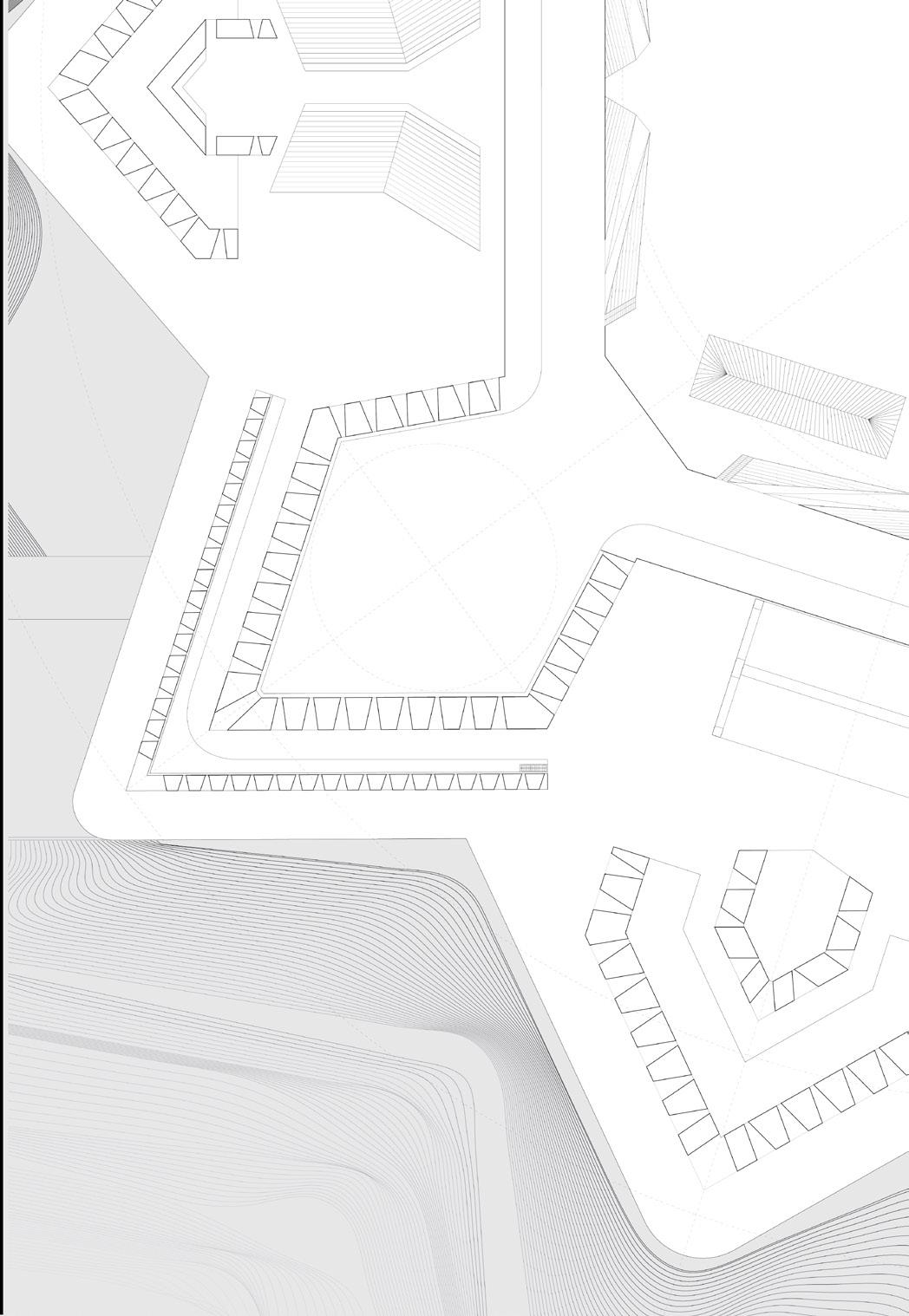
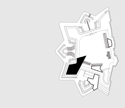
This fort has two defining layers, the inner layer of 4 bastions, and an outer layer of 3 ravelins. This was a common design, where the ravelins protected the curtain wall of the inner fort, so as to leave no obvious weak points. The plan of the fort takes its overall form from the idealized version, and details from the as built version.
The most interesting moments occur in places where the symmetry is broken. Such moments did not exist in the original plan and became important as I moved forward to the model fabrication phase of the project.
In the detail view, you can see a close look at a bastion and 2 ravelins.
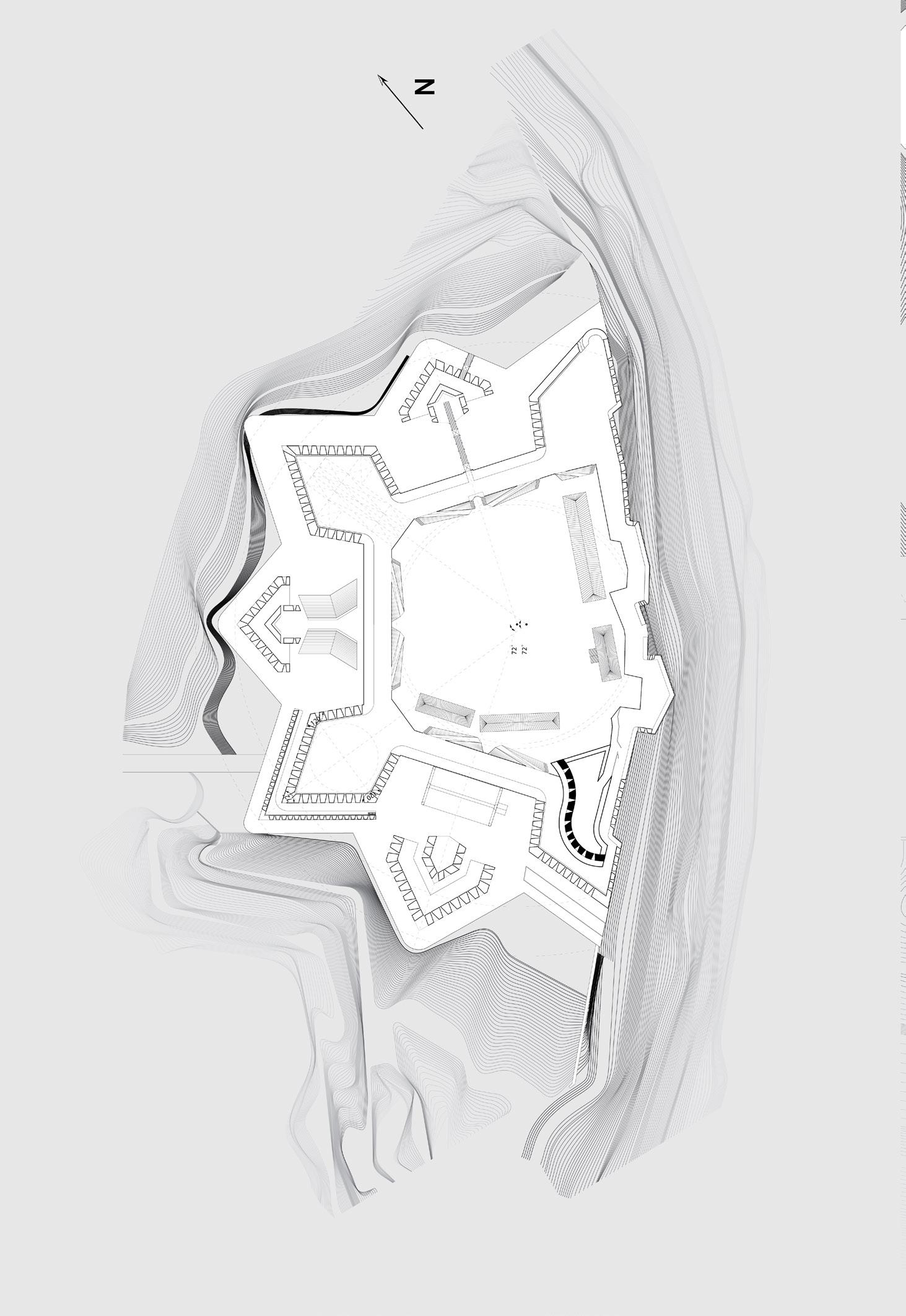
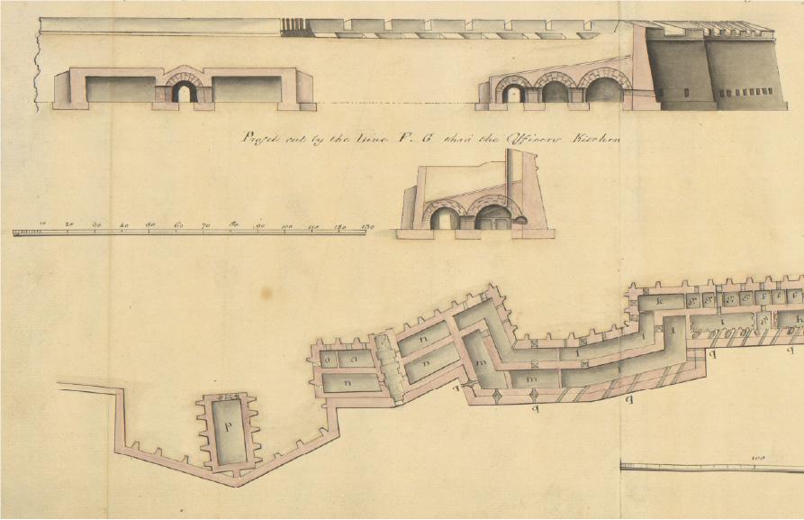
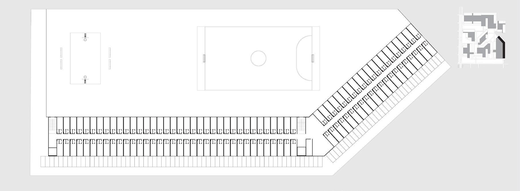
This is a cut plan of drawing of the fort and it demonstrates a way to inhabit what is essentially a very thick wall.
aspect was important in my housing proposal, part of which you can see on the right.

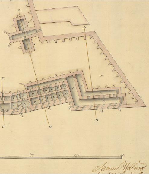
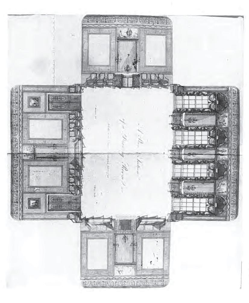
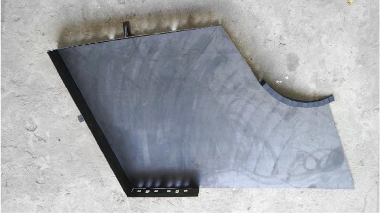
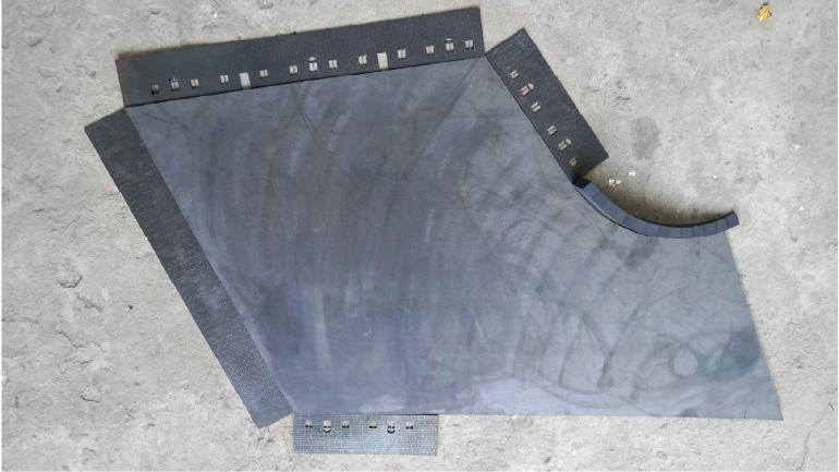
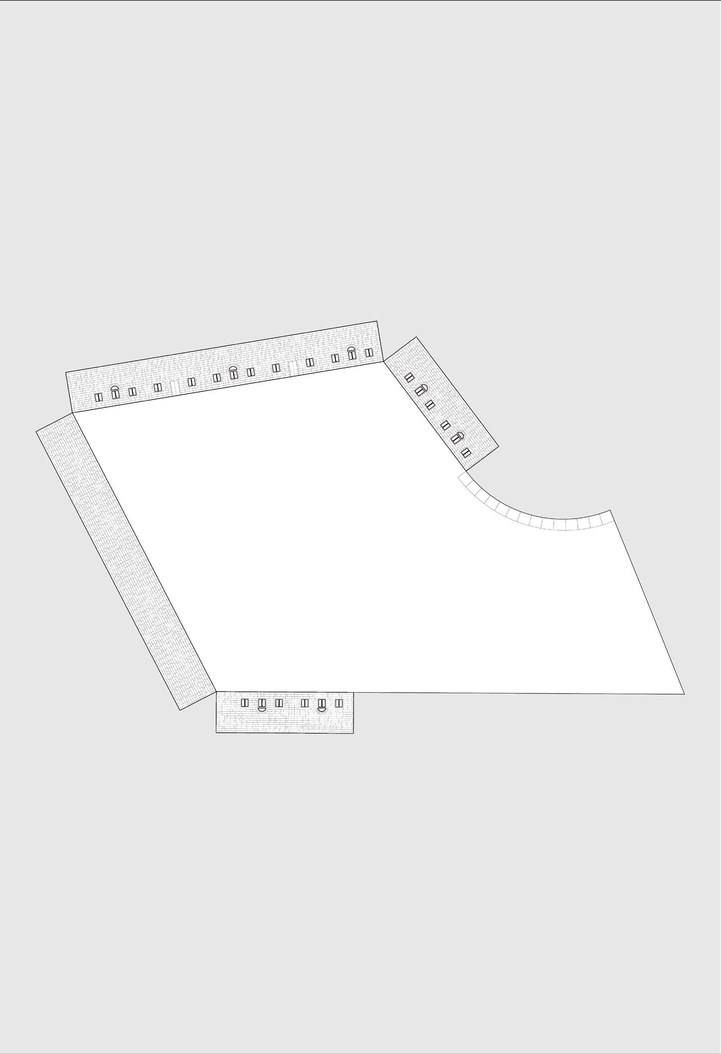
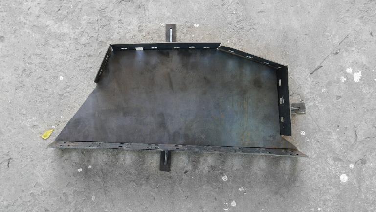
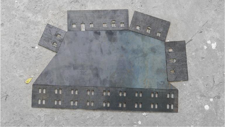
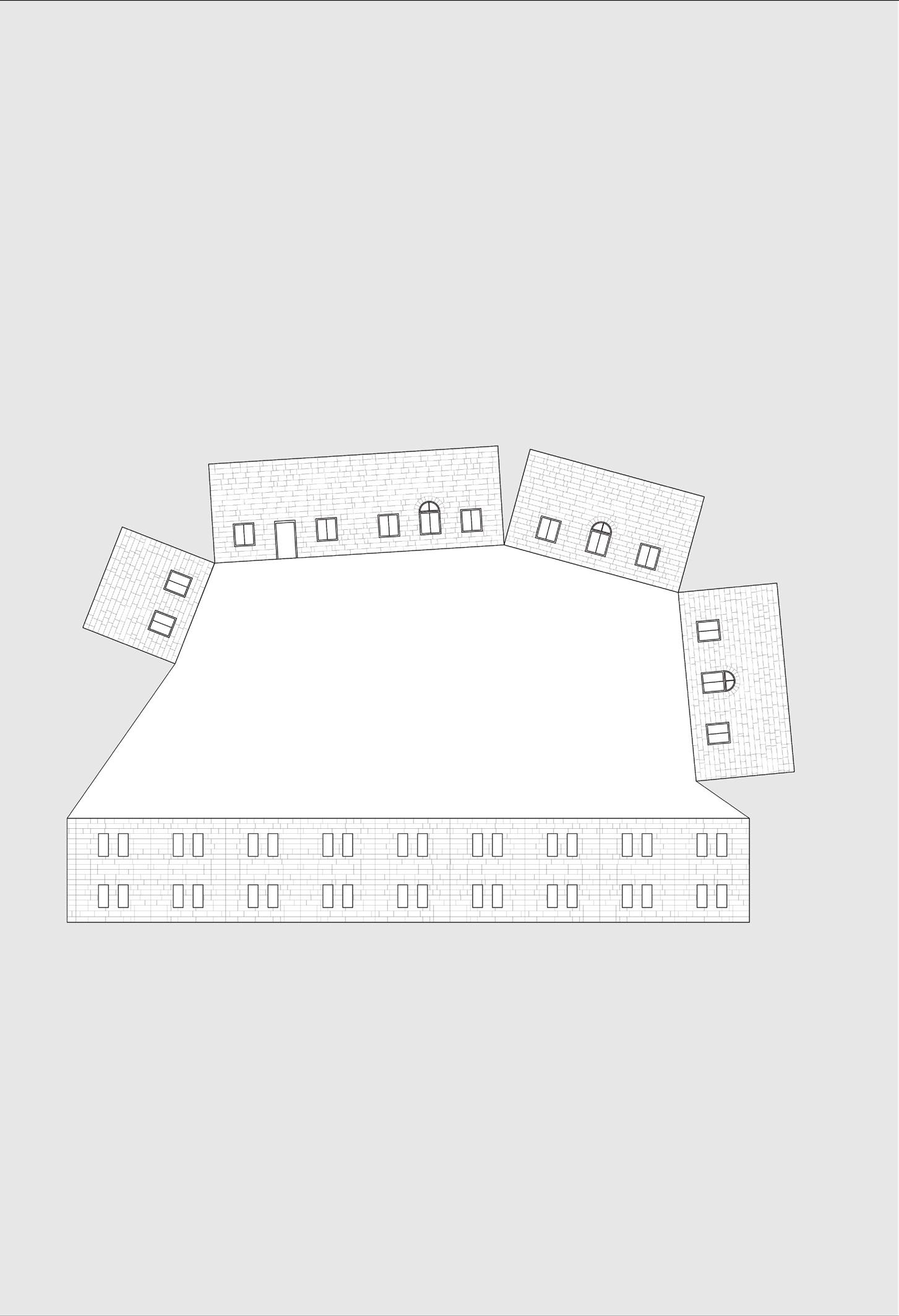
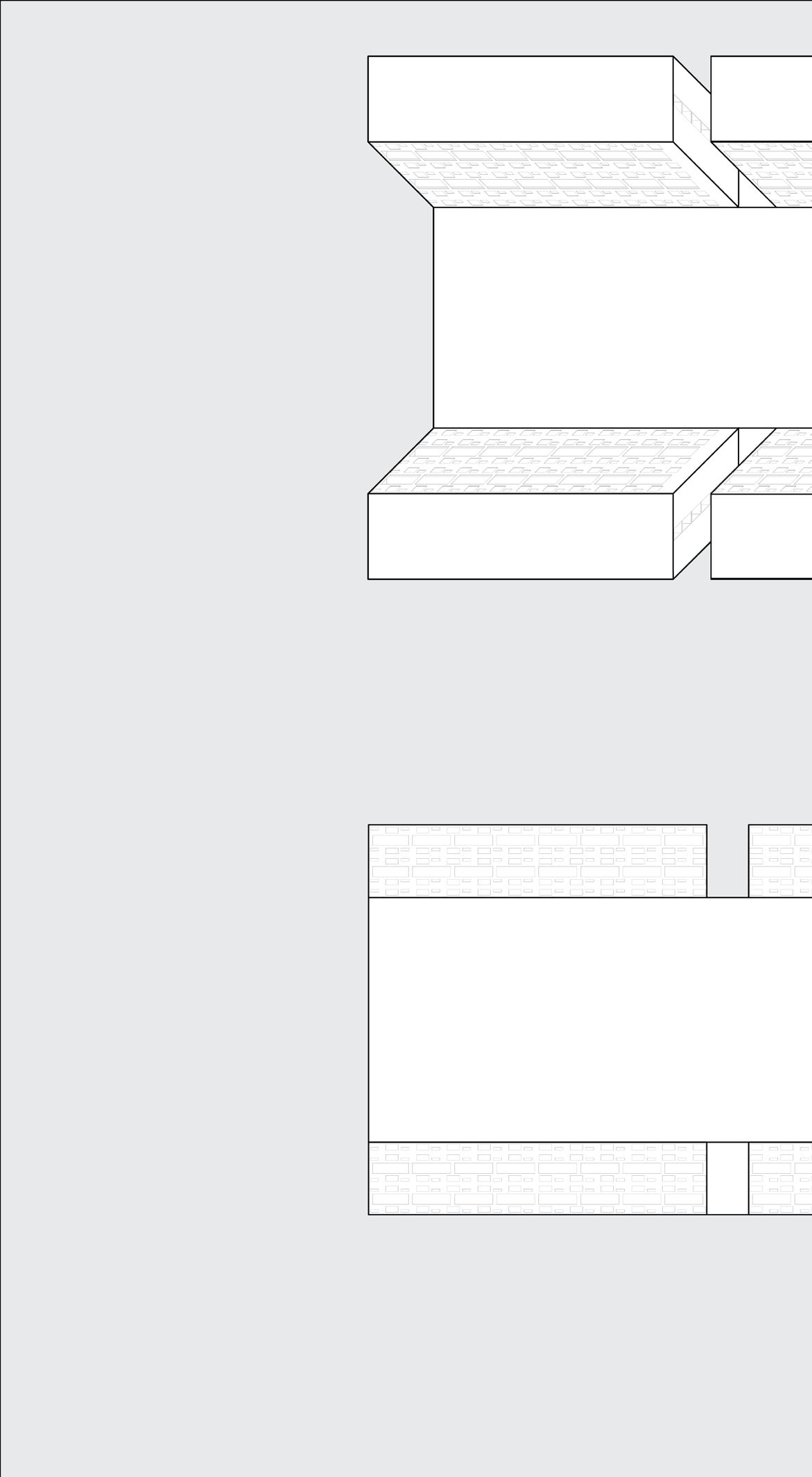
The method chosen for the fabrication of the model is called ‘Developed surface’ which is a technique to present 3d structures in 2d space. This was used in the 17th century to as a representation of indoor and outdoor spaces, as well as entire cities.
On the right is an unfolded drawing of a structure in the fort similar to the drawing you see above using the technique of developing surface.
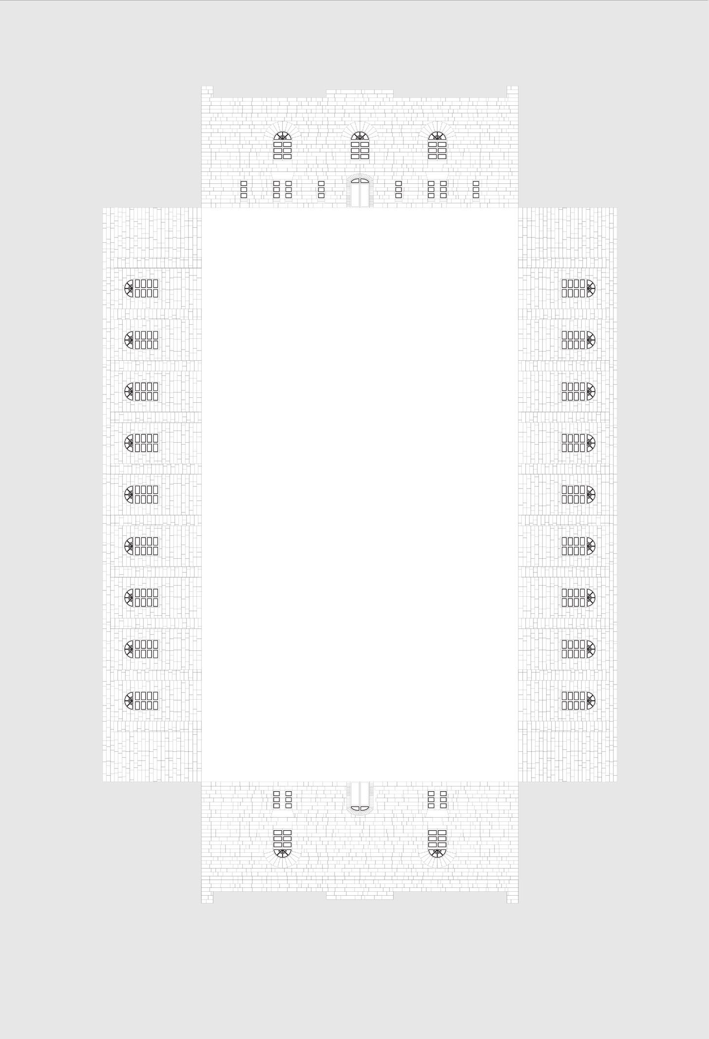
Taking this technique one step further, I identified open spaces in the fort, which were surrounded by multiple buildings.
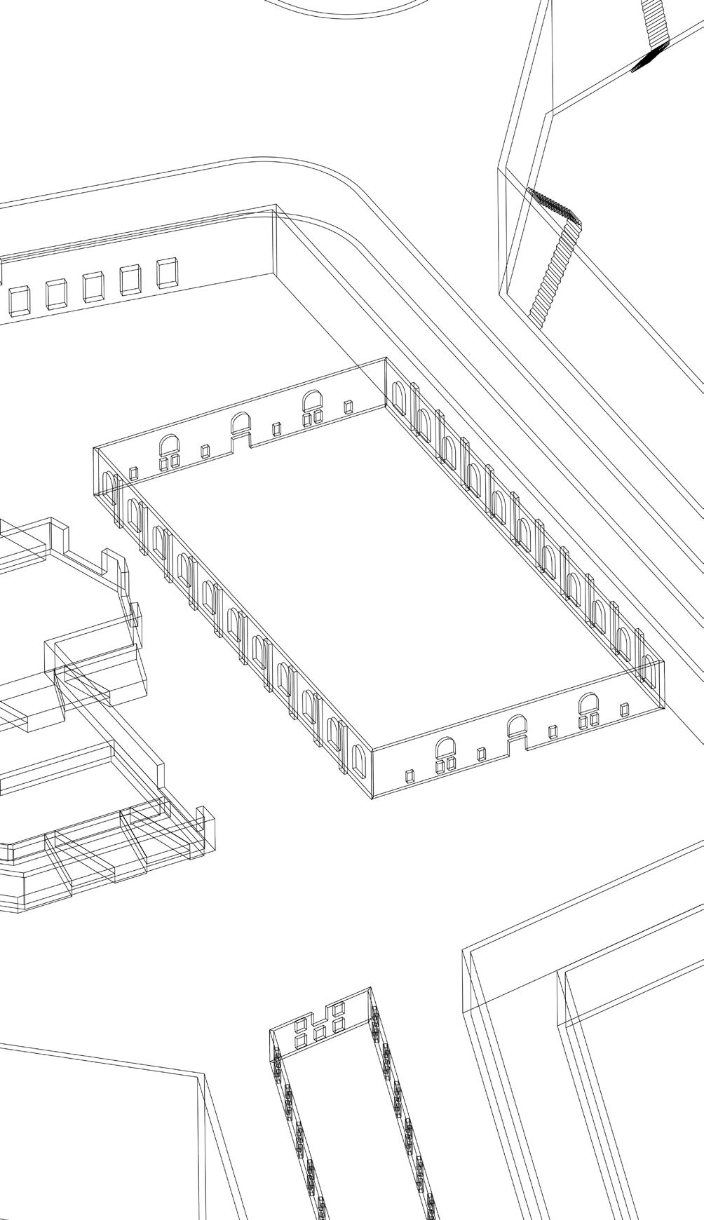
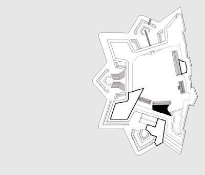
The walls of the plaza space seen in the middle here is formed by elevations of 4 different structures. It’s unfolded version can be seen on the right.
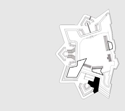
Plaza locations, La Citadelle de Québec.
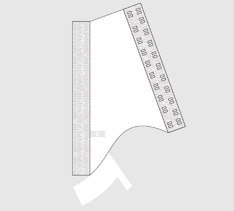
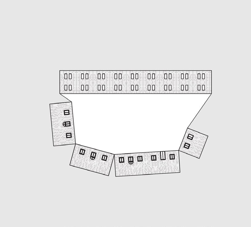
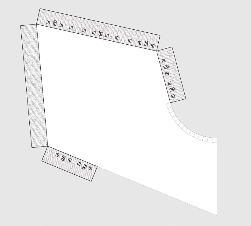
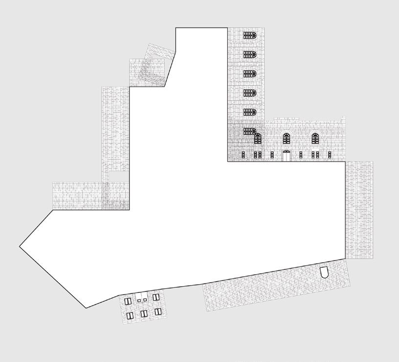
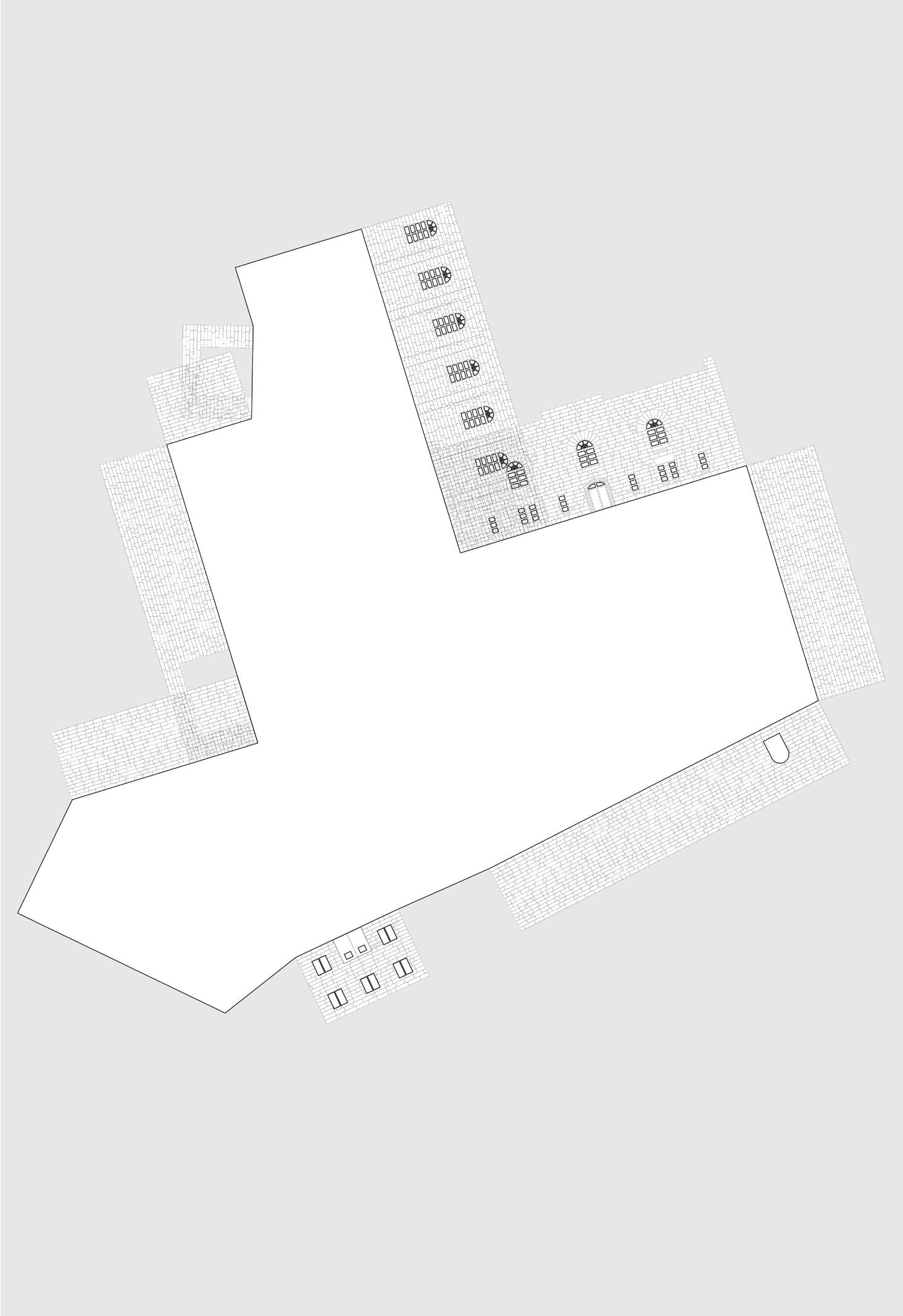
4 such plazas were identified. All of them have different qualities and sizes.
One is a wide passageways, One is almost completely enclosed, another has only one exit, whereas the original plaza is spilling from various openings.
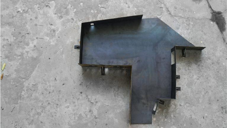
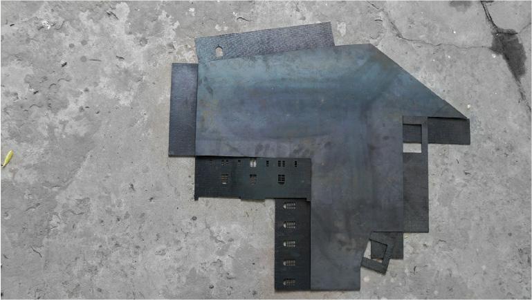
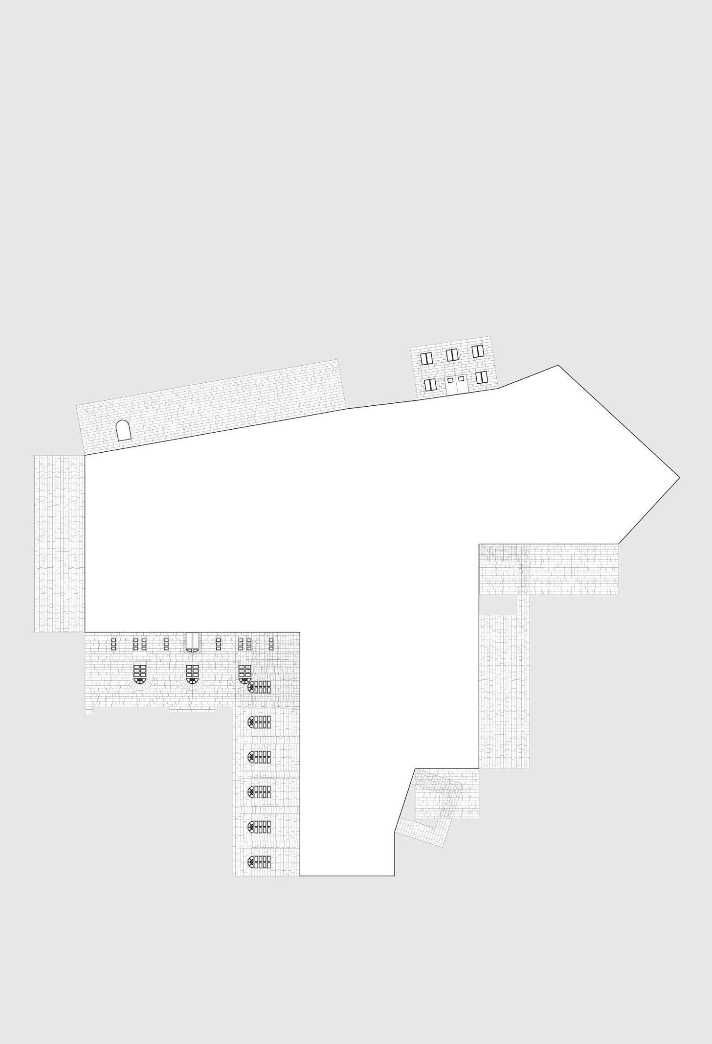
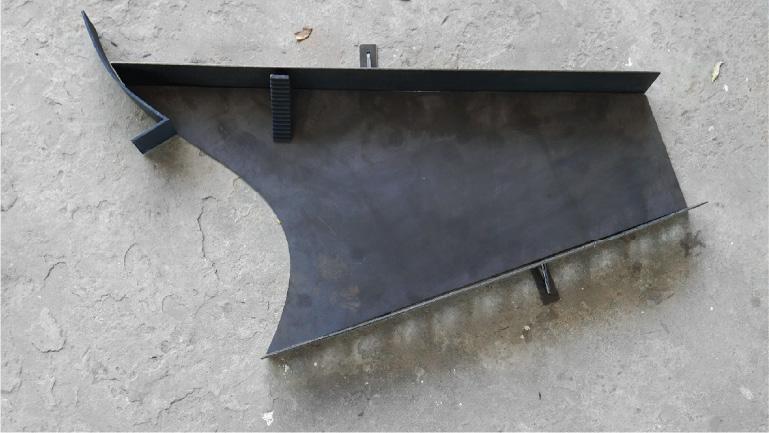
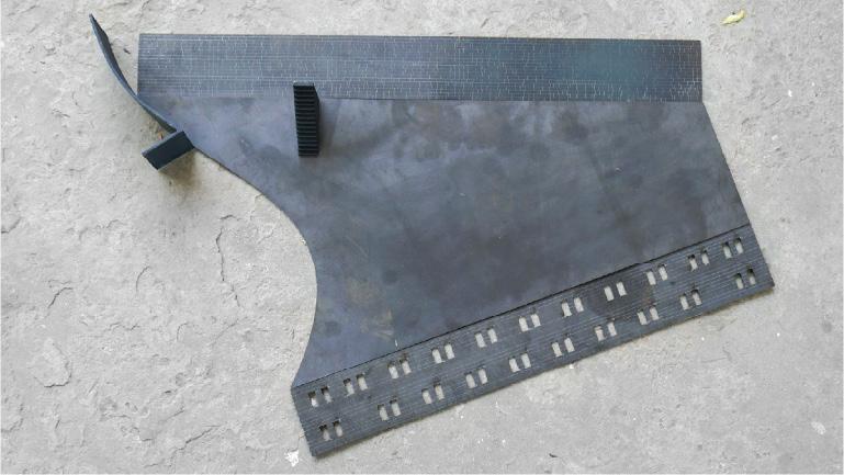
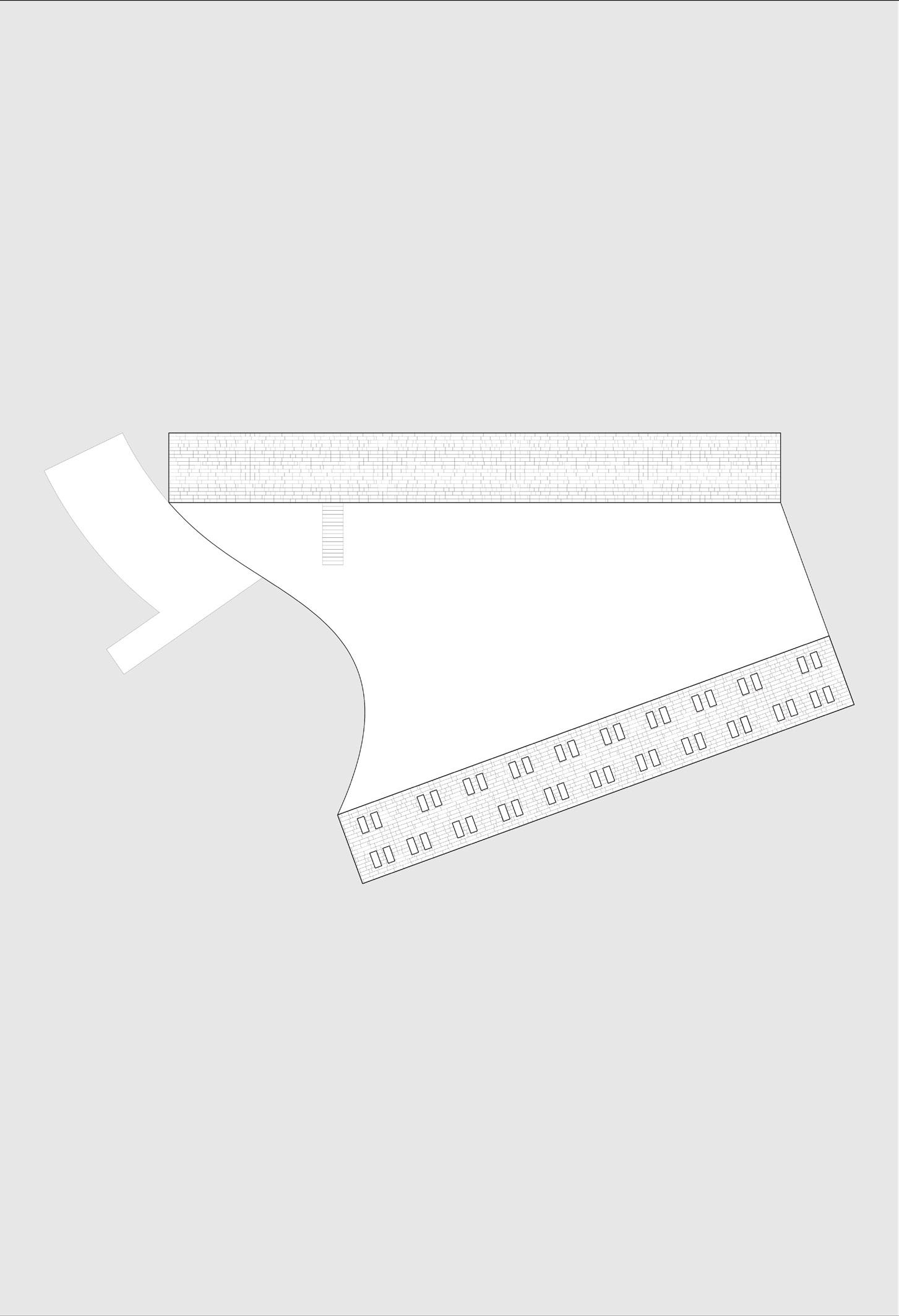
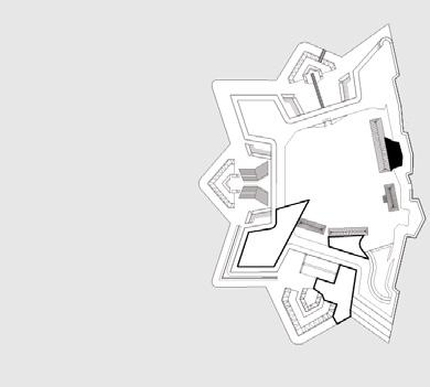
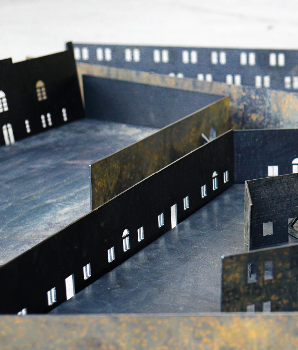
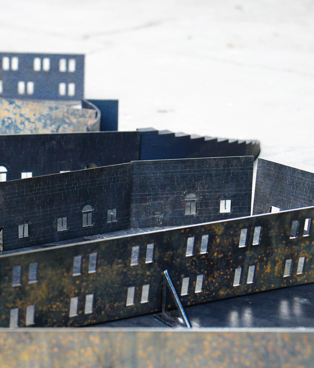
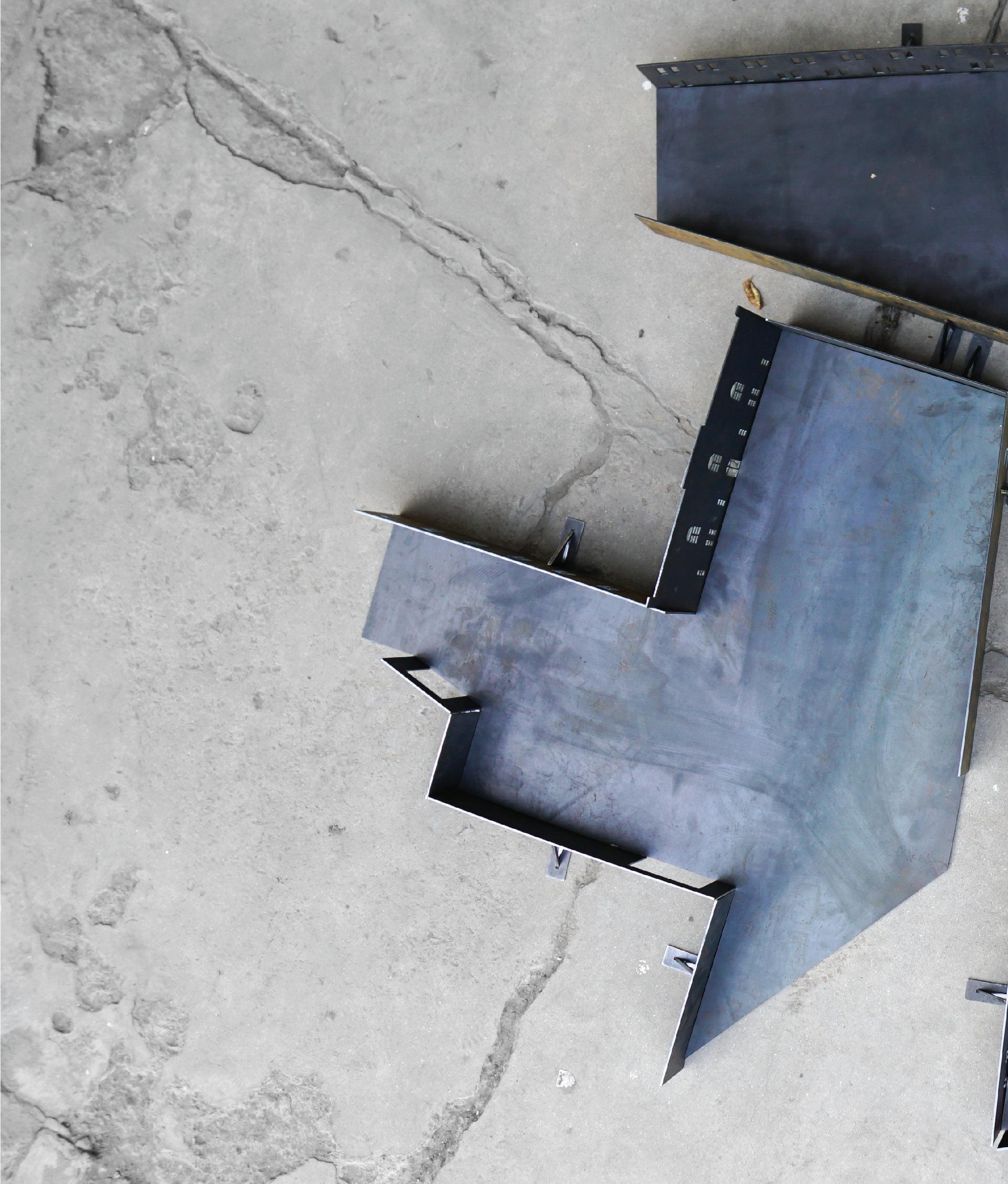
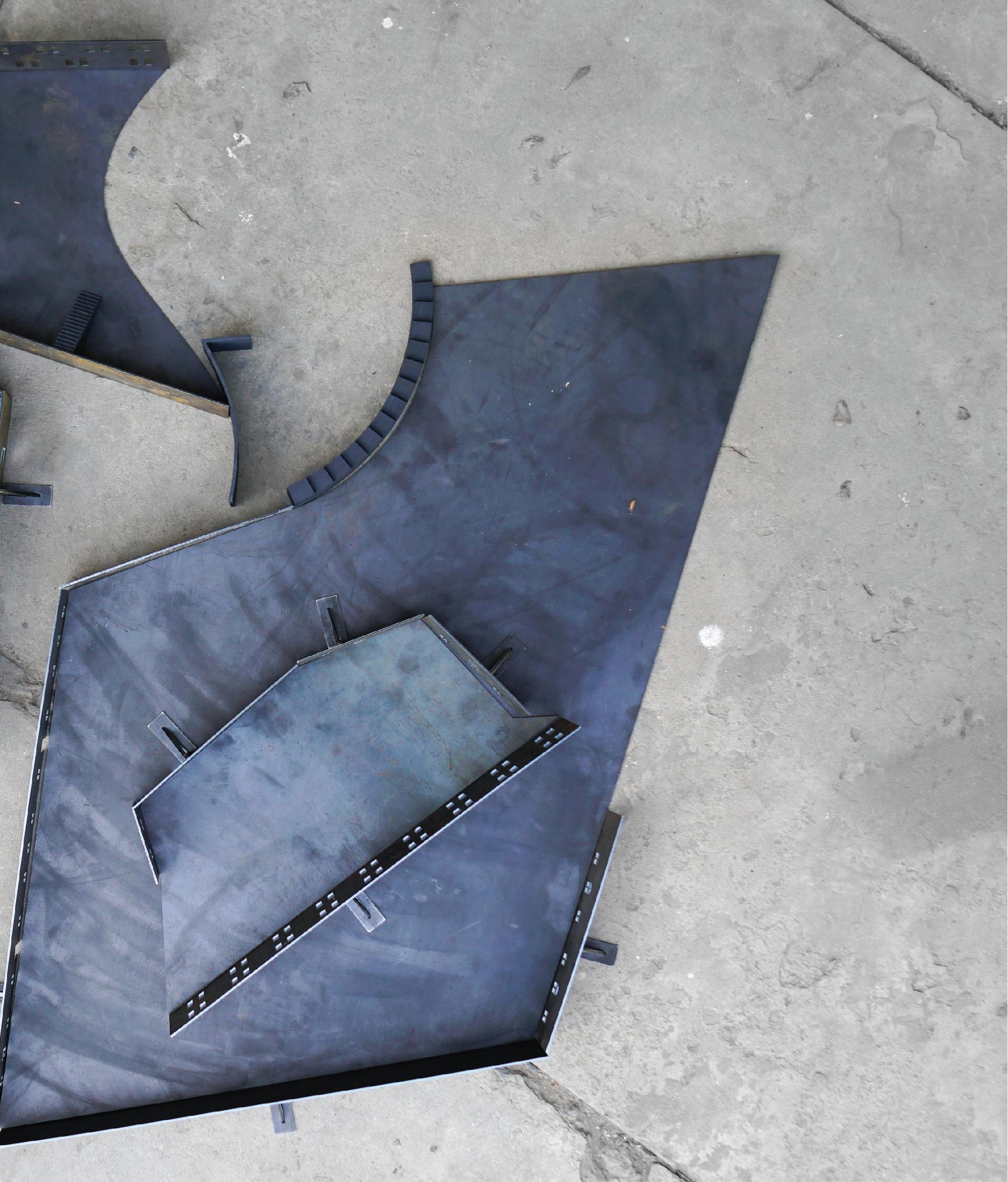

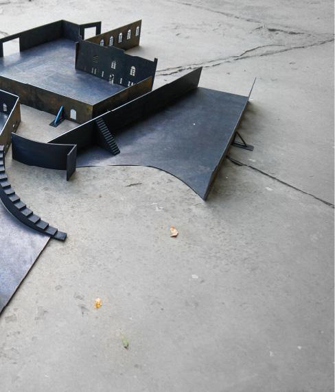
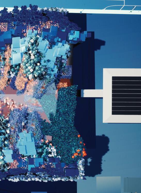
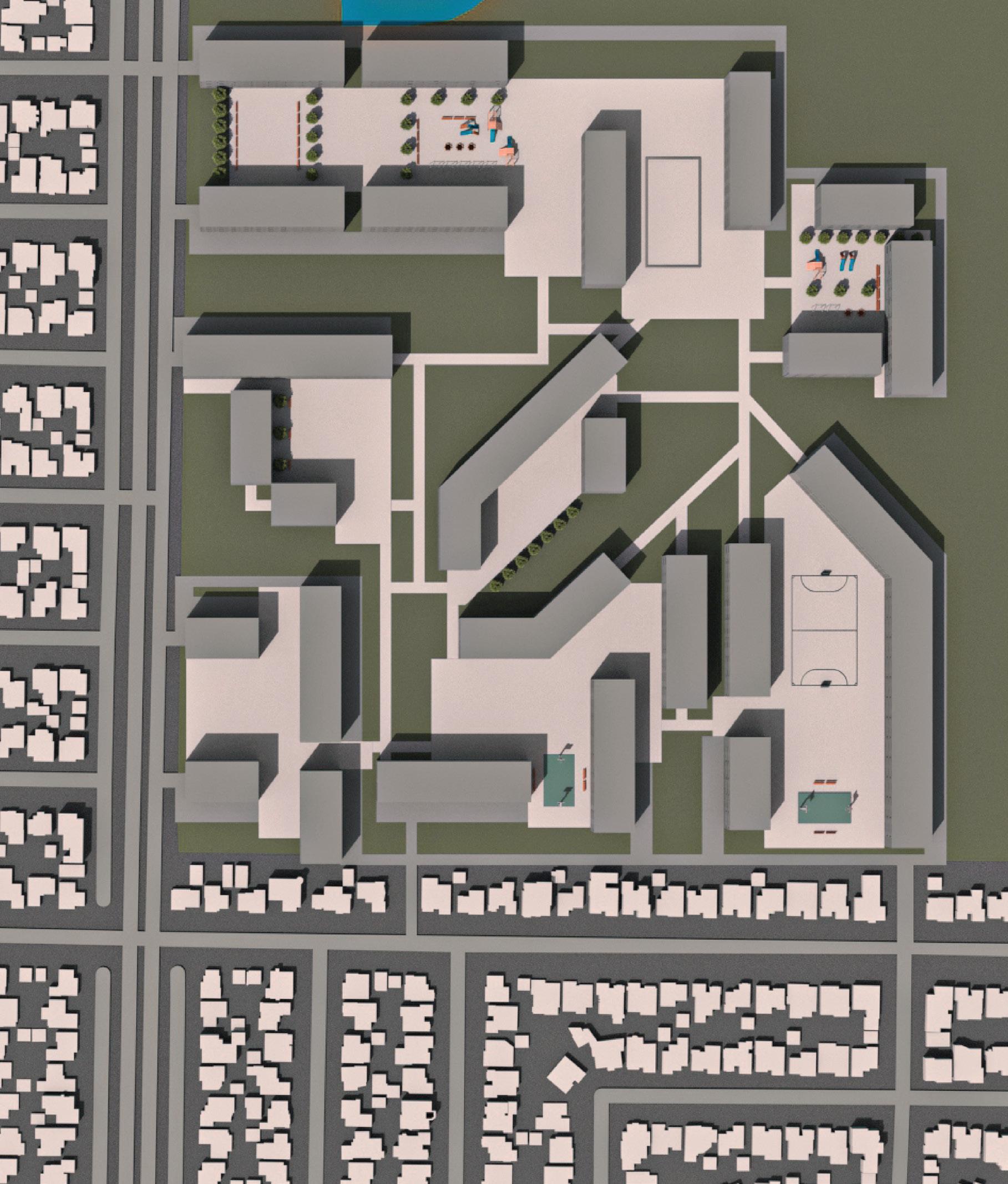
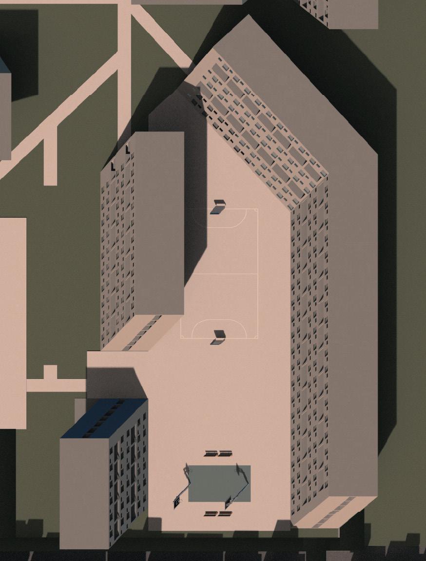
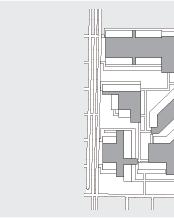
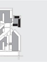
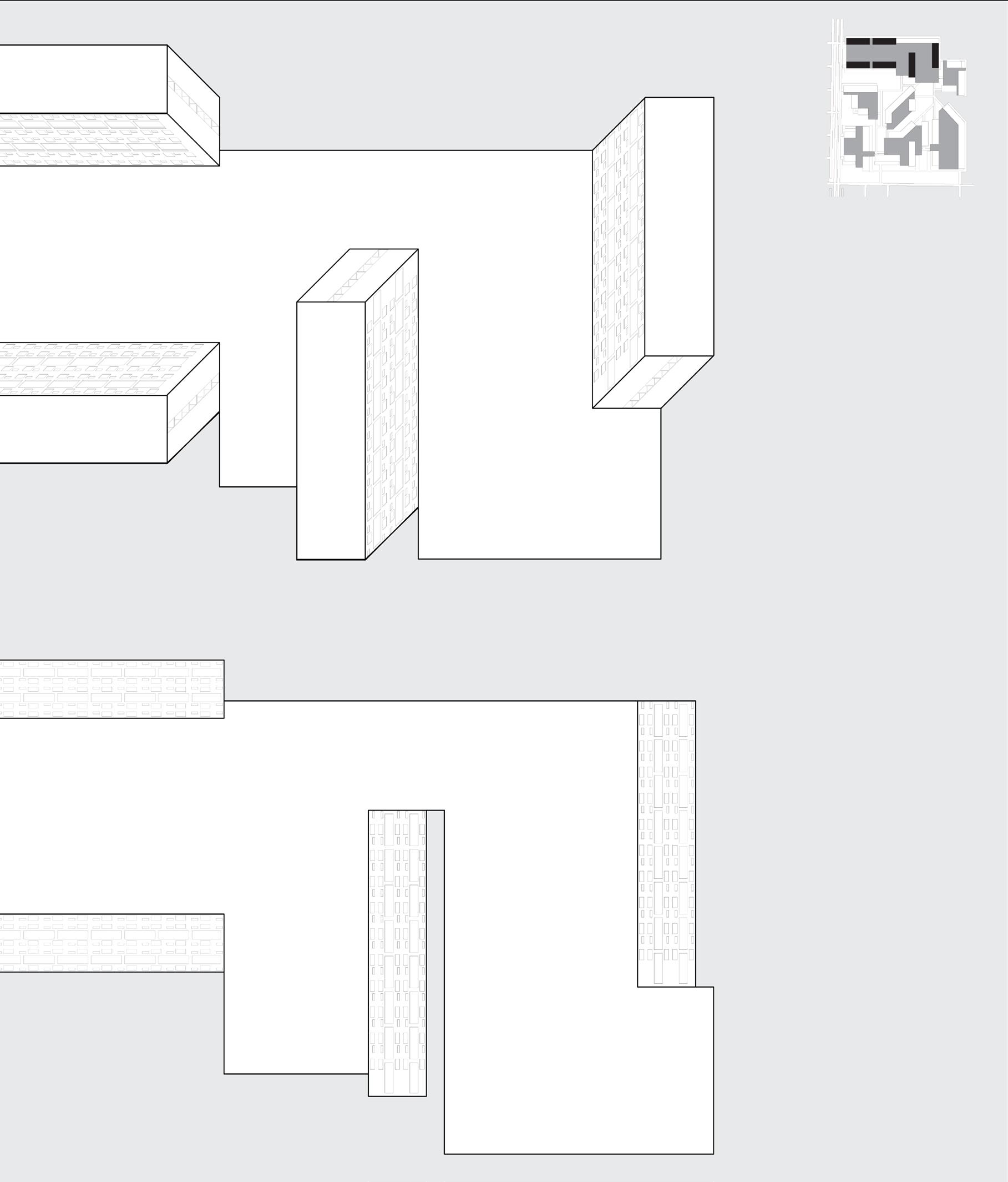
The chosen site for my social housing project was the El Dorado golf course in Long Beach. I chose to limit the project site to the lower left quadrant of the golf course, as marked in the drawing on the right.
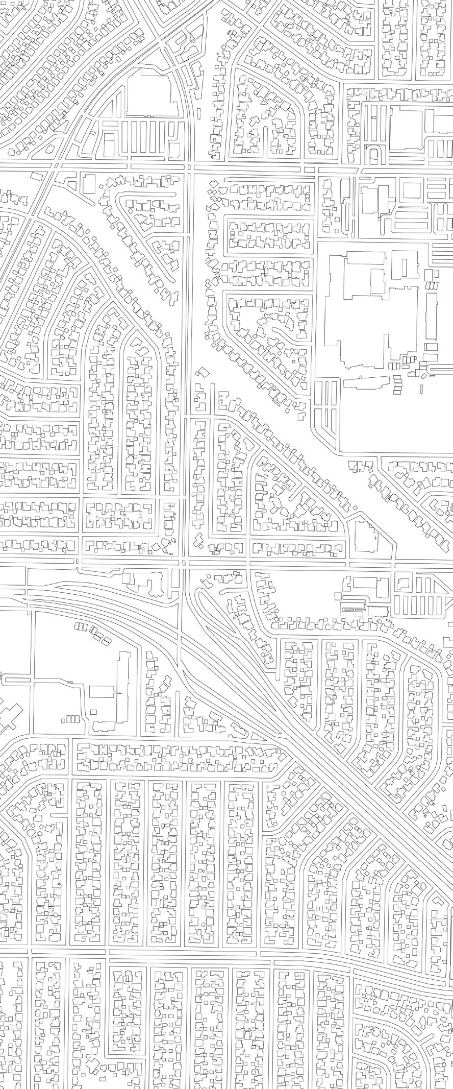
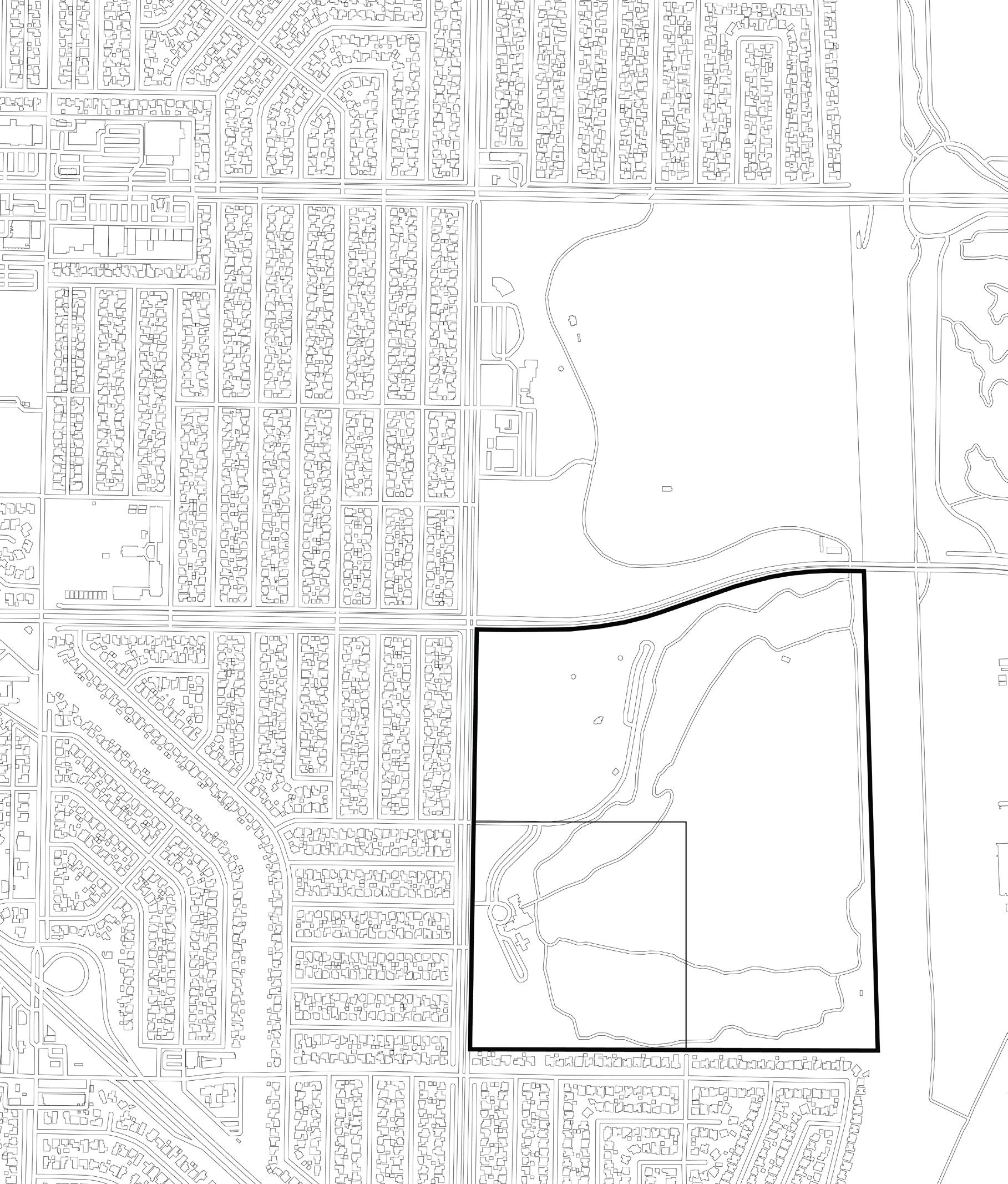
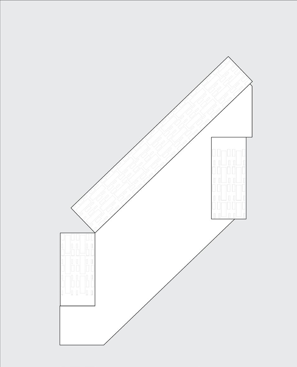
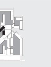
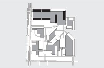
My site is demarcated by these two roads that are perpendicular to the site. I was interested in the urban grid of the road network and wanted to extend that logic to my site. There is an underlying centerline grid generated from the road network which became the organizing element of the site.
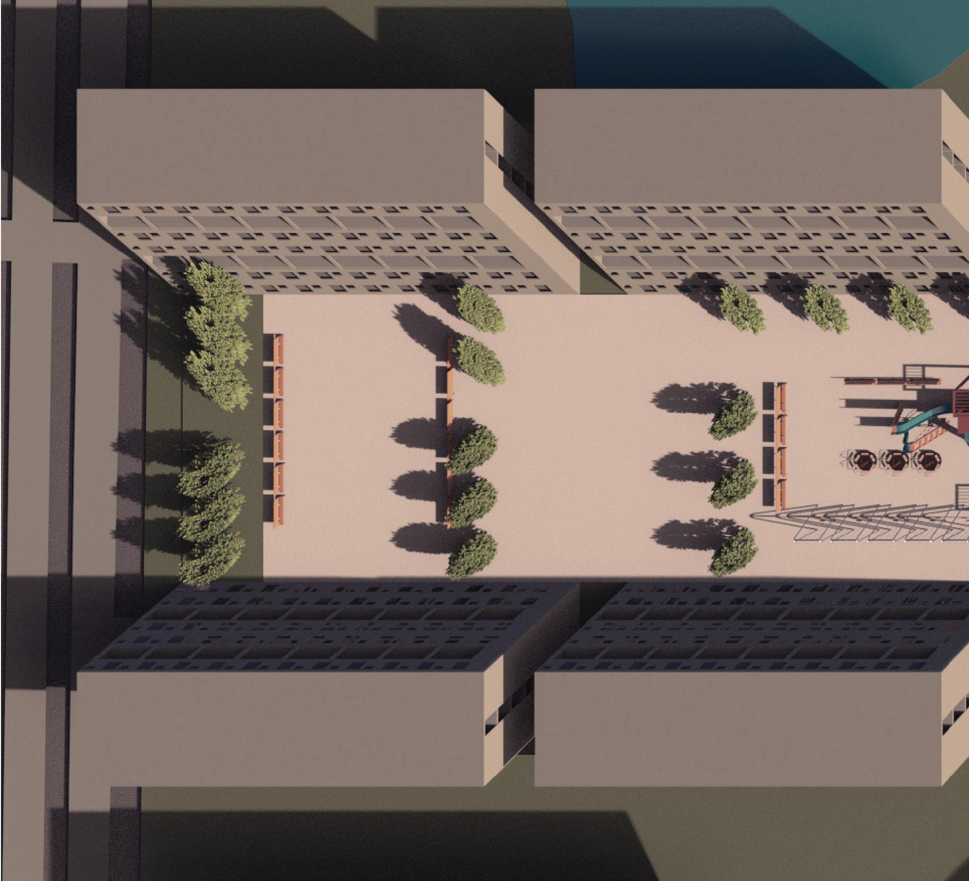
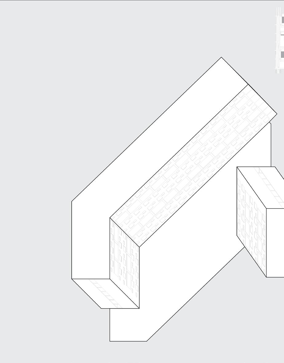
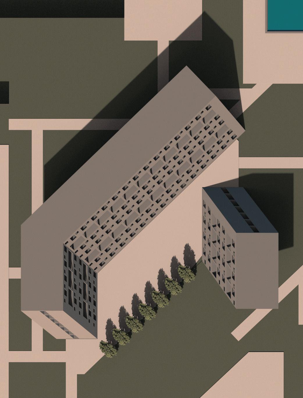
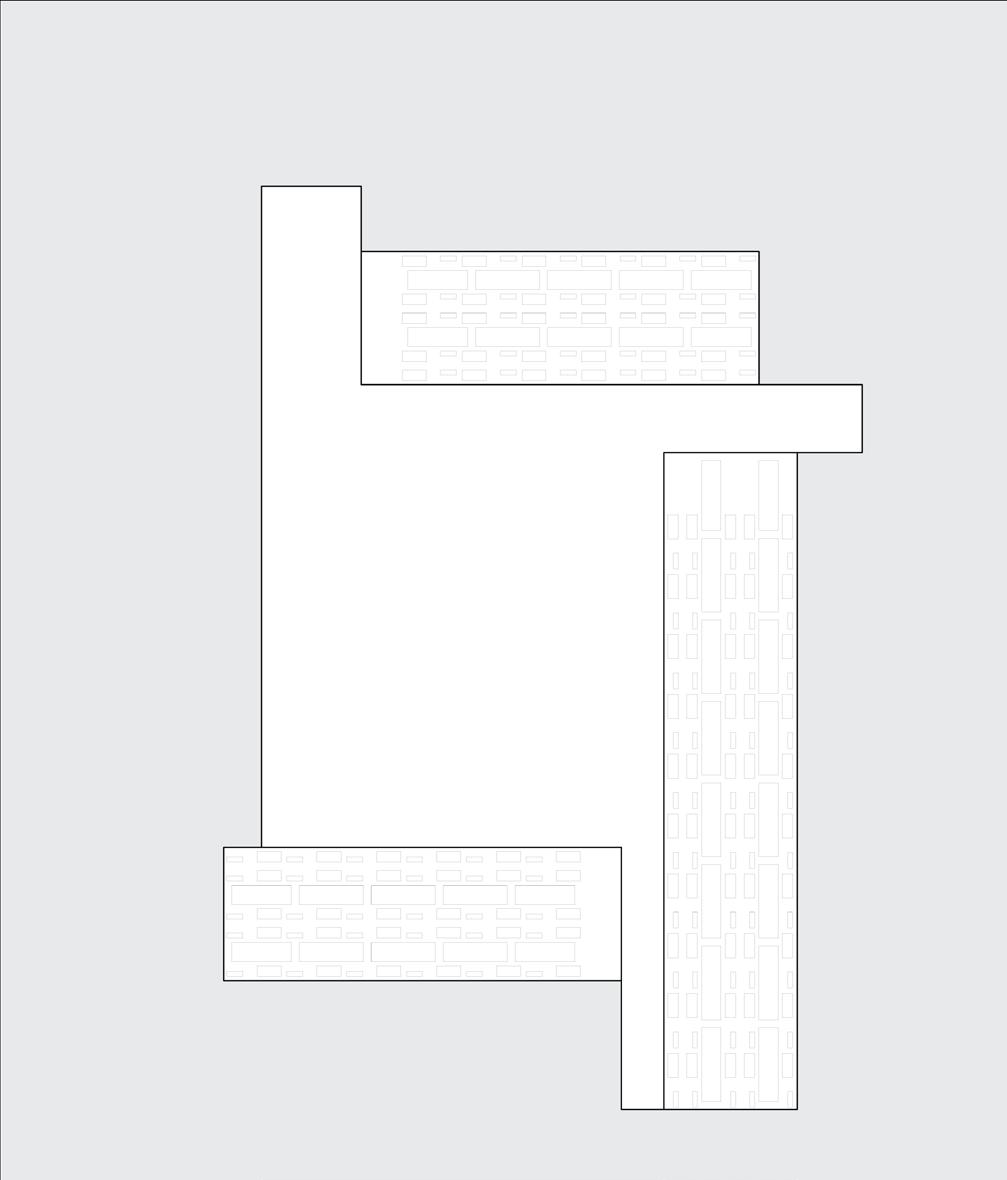
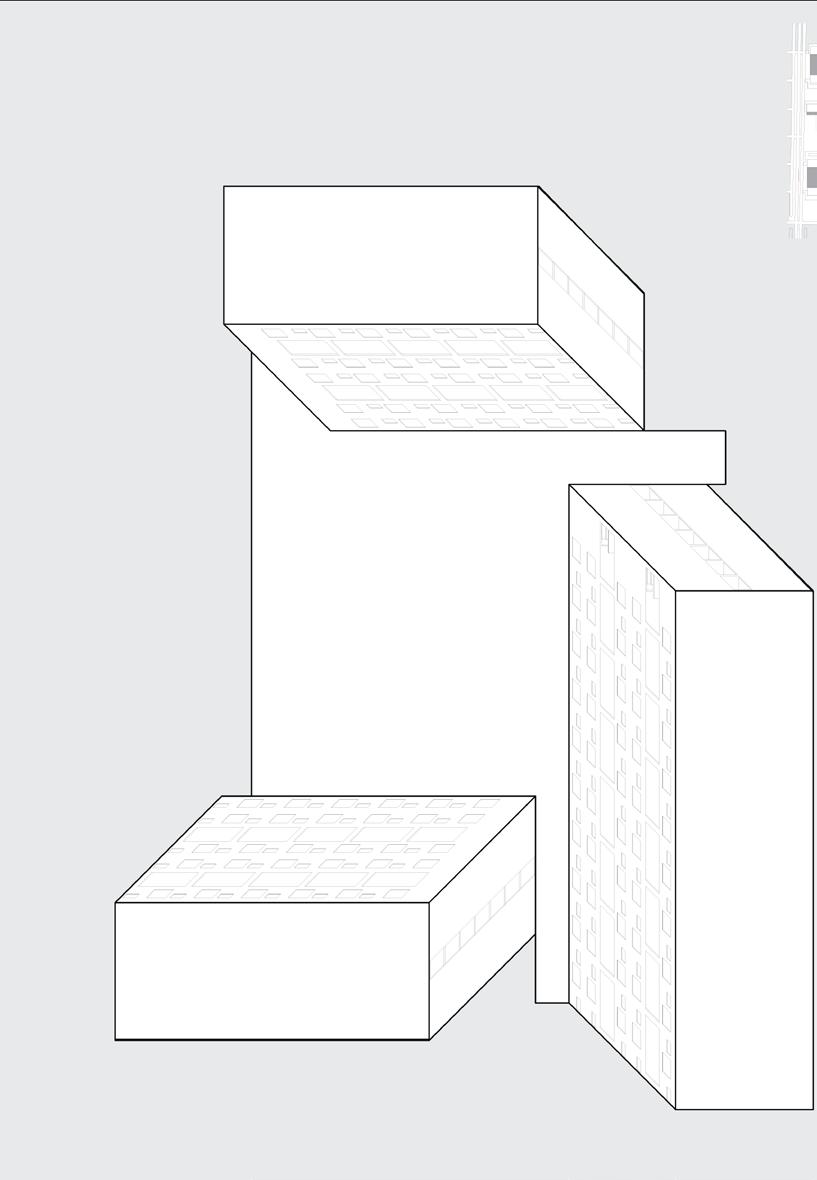
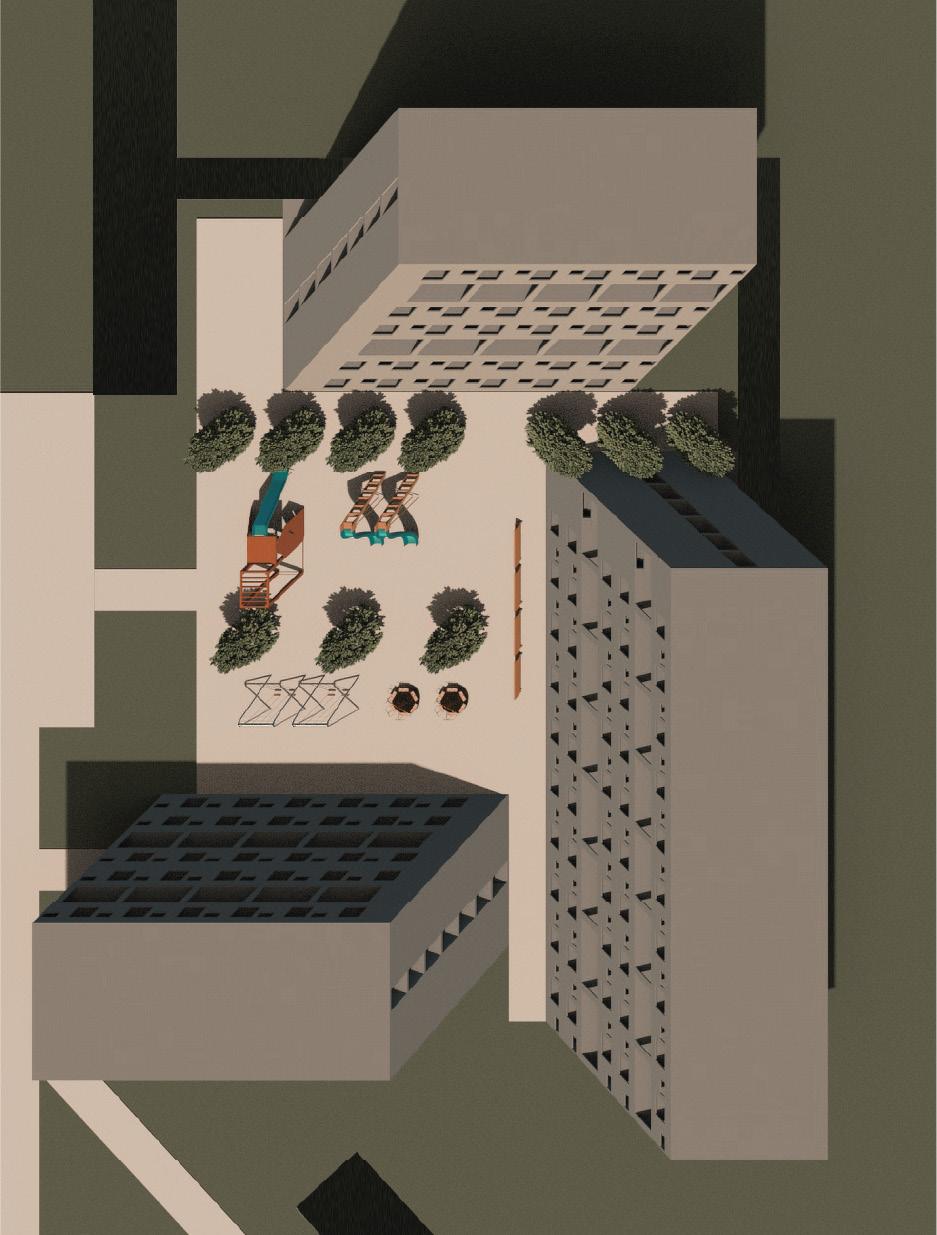
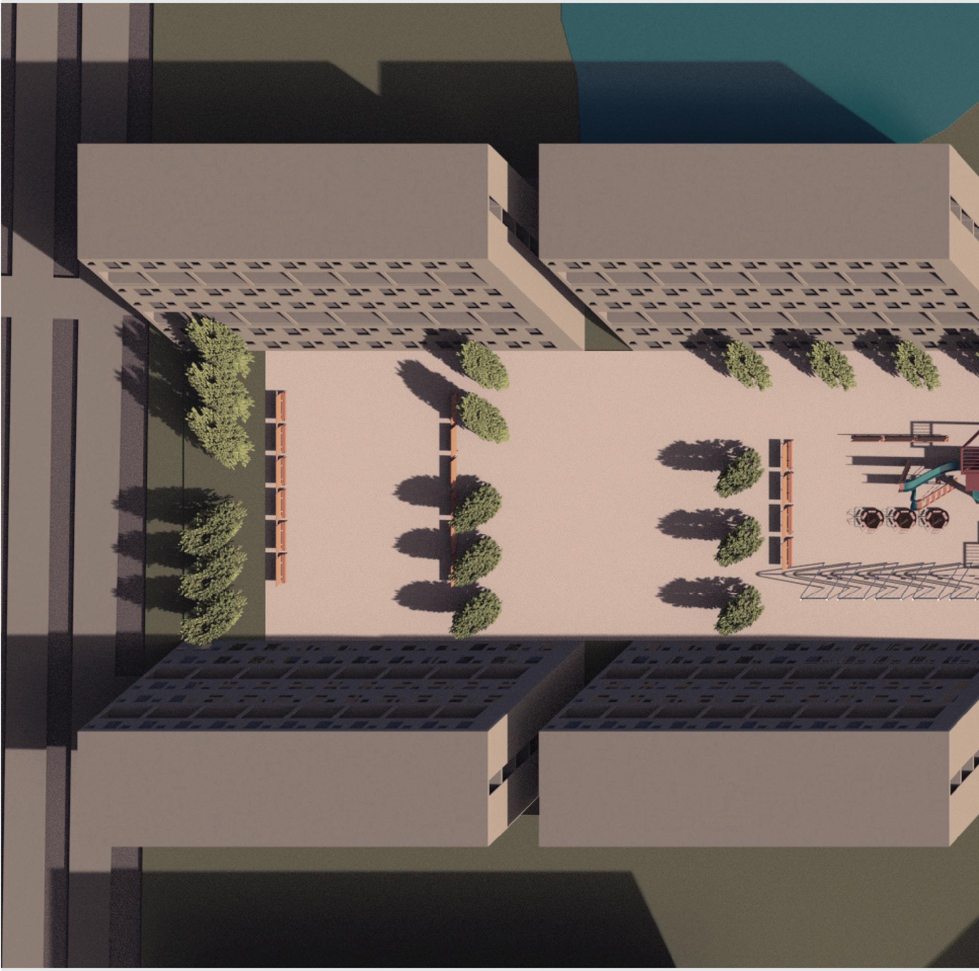
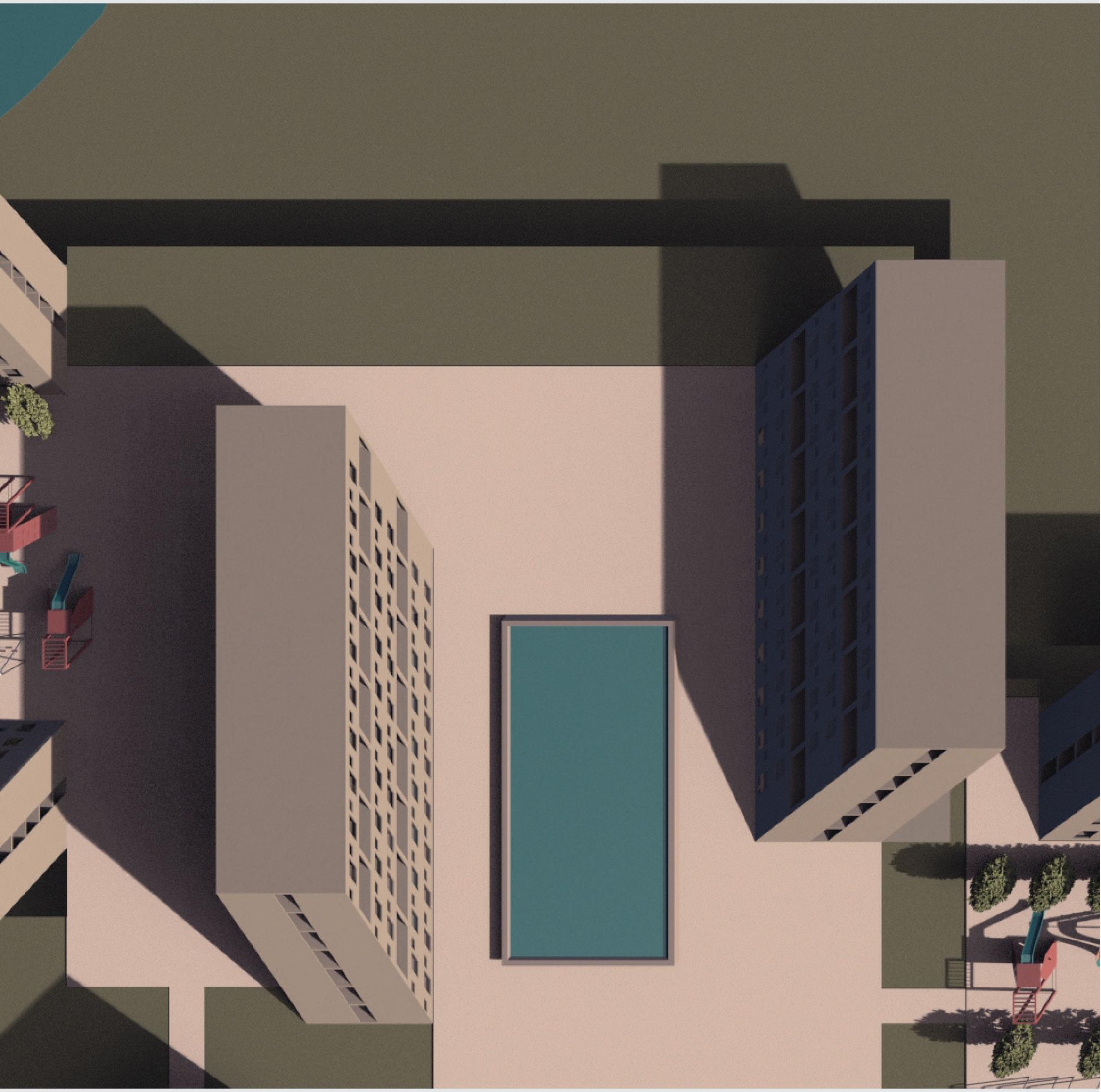
The buildings you see here are placed precisely on the gridlines and dictate the shape of the resulting plazas.
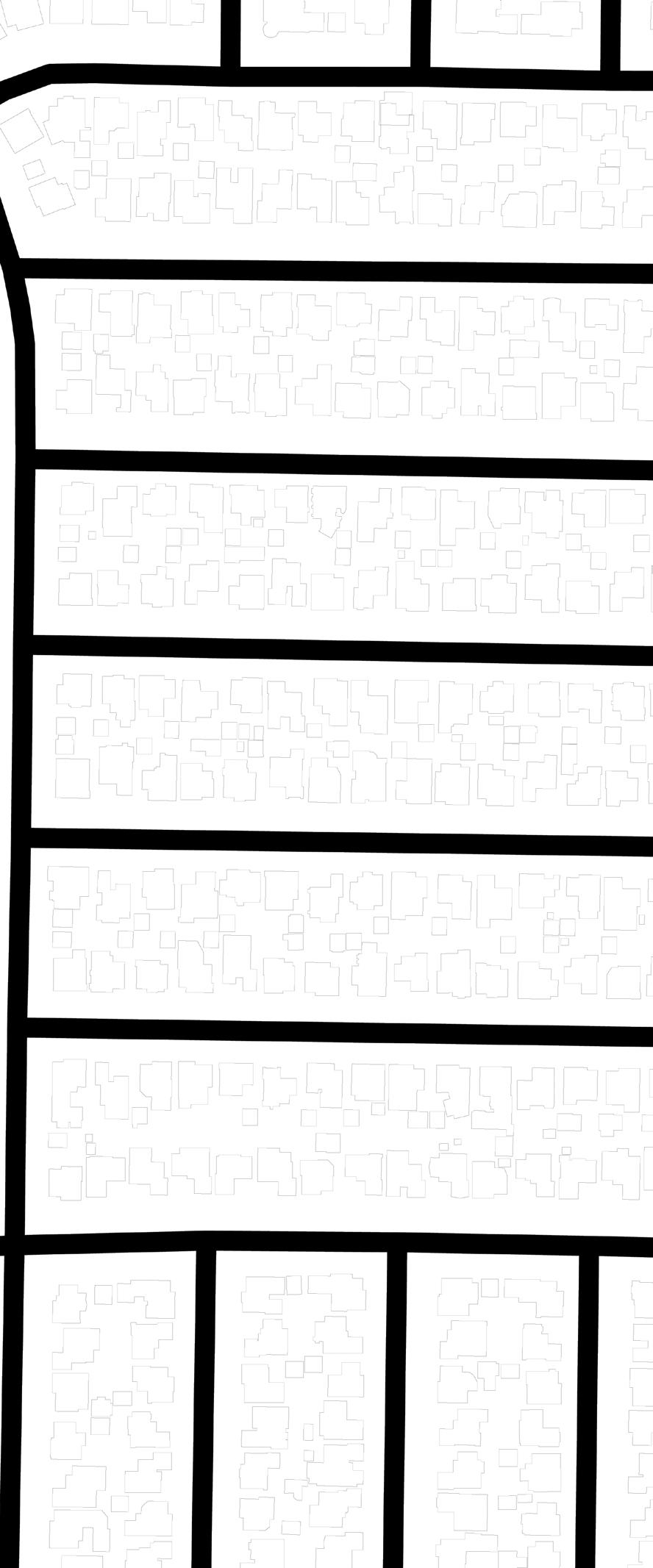
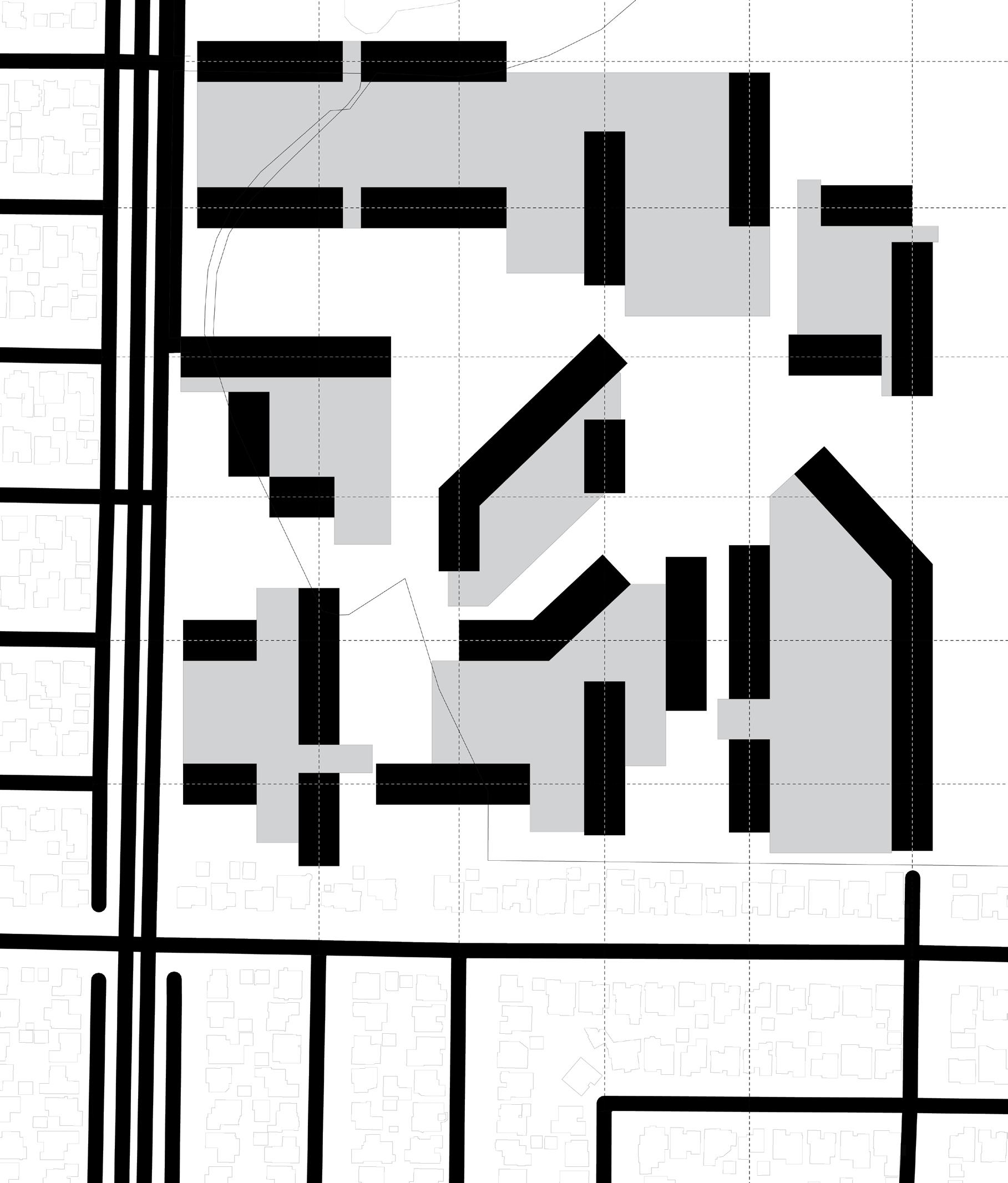
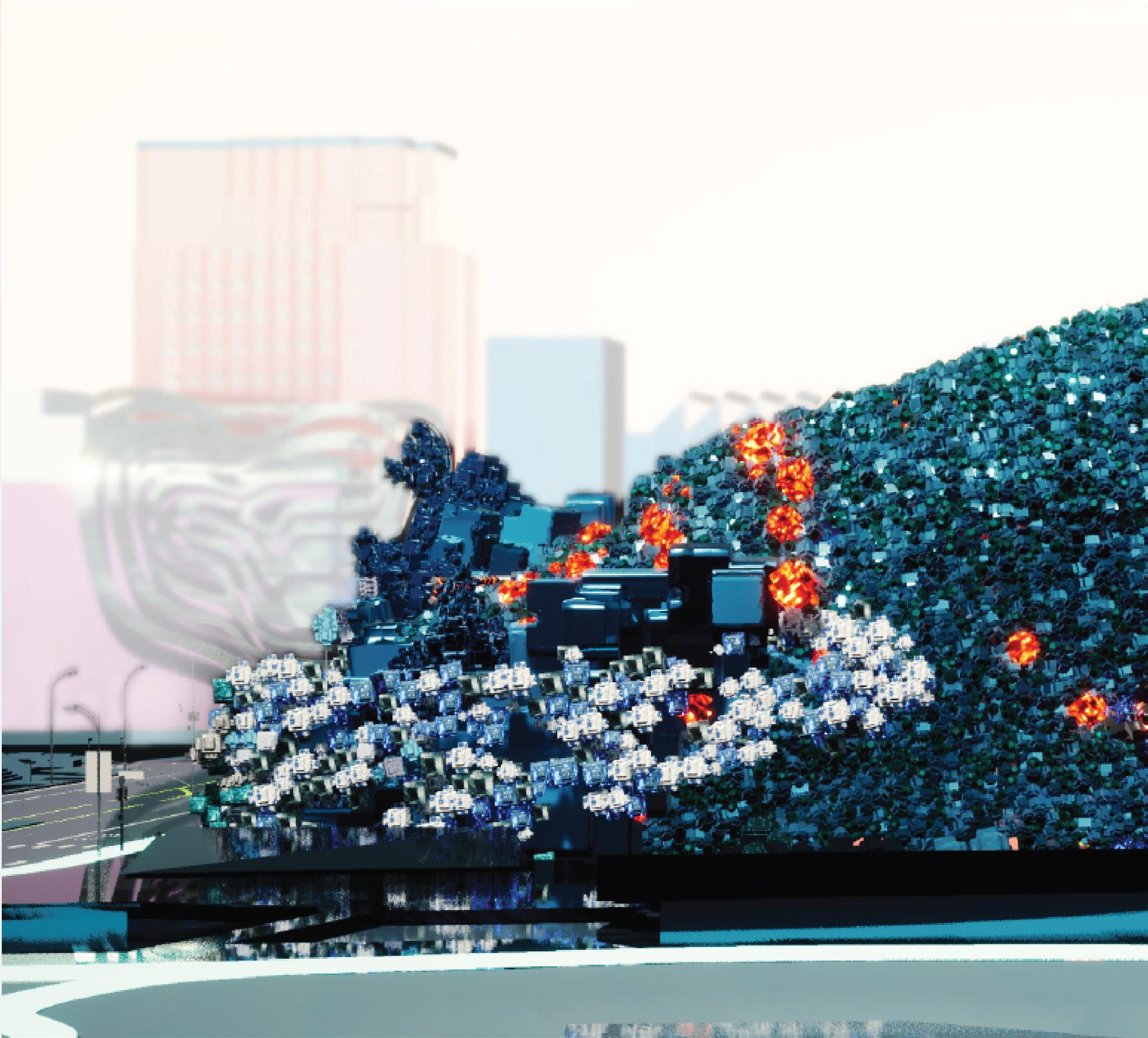
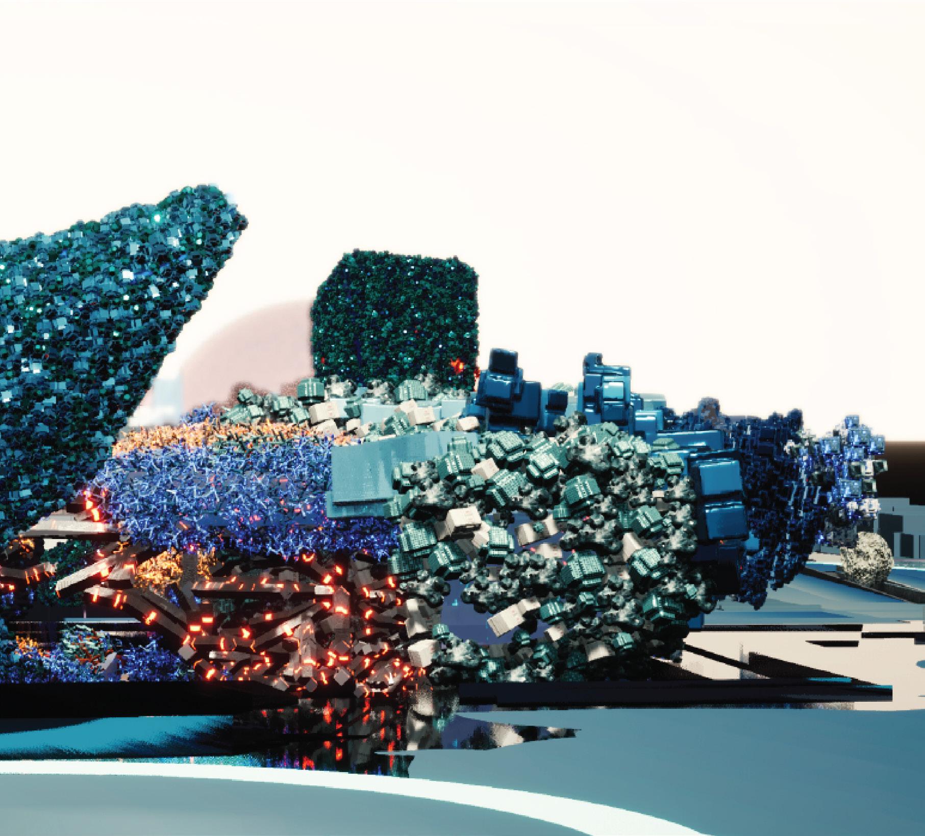
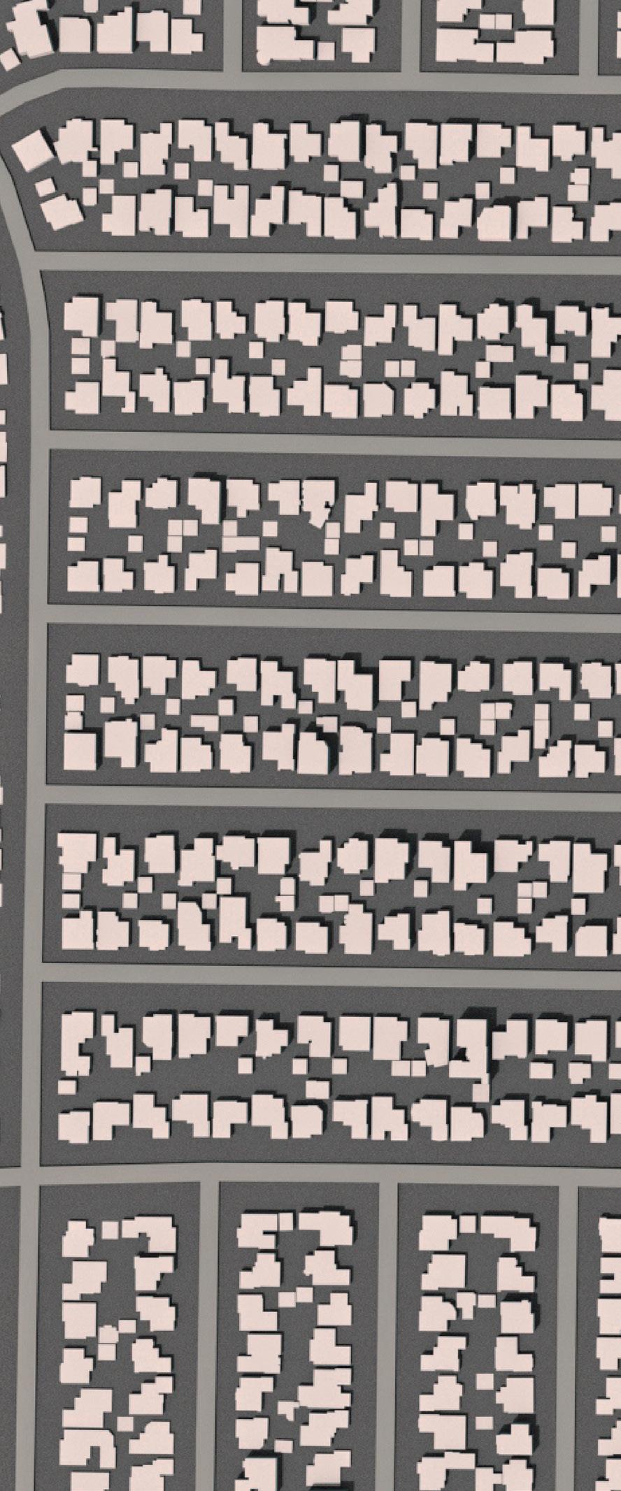
This drawing shows the scalar shift happening once the threshold between road and golf course is crossed. The plazas are situated so as to be a continuation of the road network.
The urban condition is reversed, and now all the housing is squeezed on to the roads and the residential space becomes the plaza.





Architects:
Arcop (Pvt) Ltd.
Client:
Telenor Group
Budget:
USD 50 Million
Built Status:
Winner:
World Architecture Community Award 2018
Nomination:
World Architecture Festival Awards in ‘Corporate’ Category.
My Responsibilities:
Was present on the site office and involved in Construction Administration phase of this project. Also contributed to Design Development phase and interior design as project progressed.

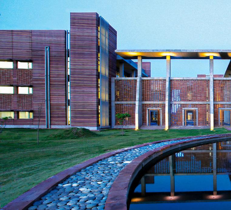
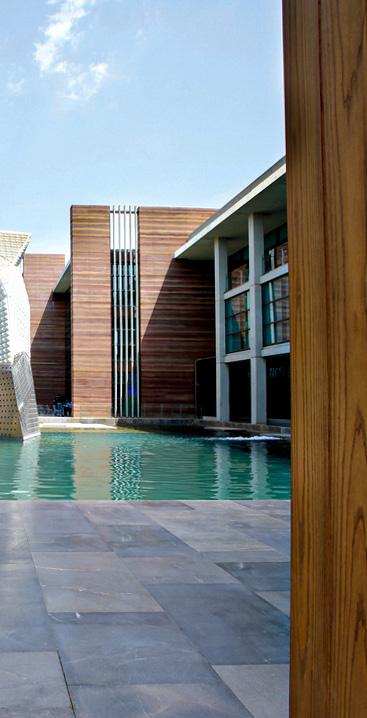
Telenor 345 is the national headquarters of the Telenor Group in Pakistan.
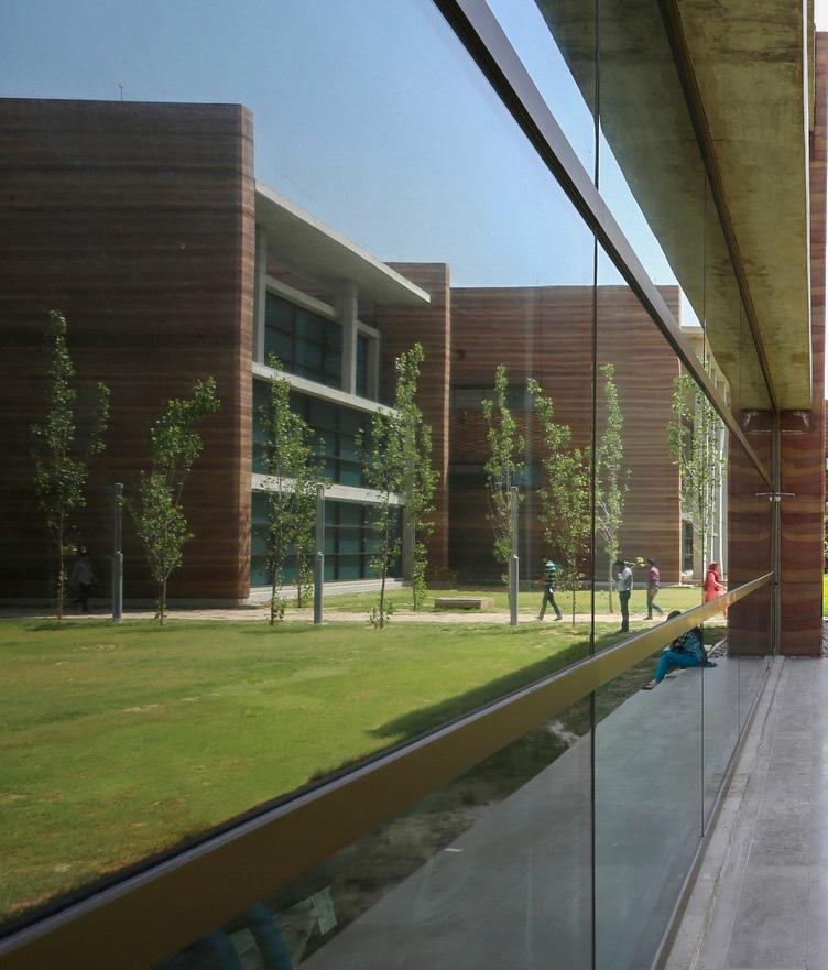
It creates a new work space paradigm, whose principles are based around sustainability, vernacular architecture, and an enriching work experience, while
relying on local materials and skills, which were critical in the design process.
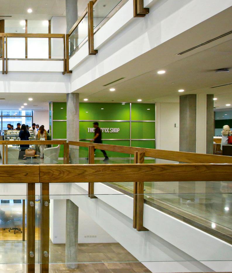
It questions the role of traditional hierarchical organizations by creating open work zones and remaining adaptable to meet the challenges of the work space.
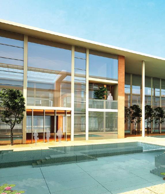
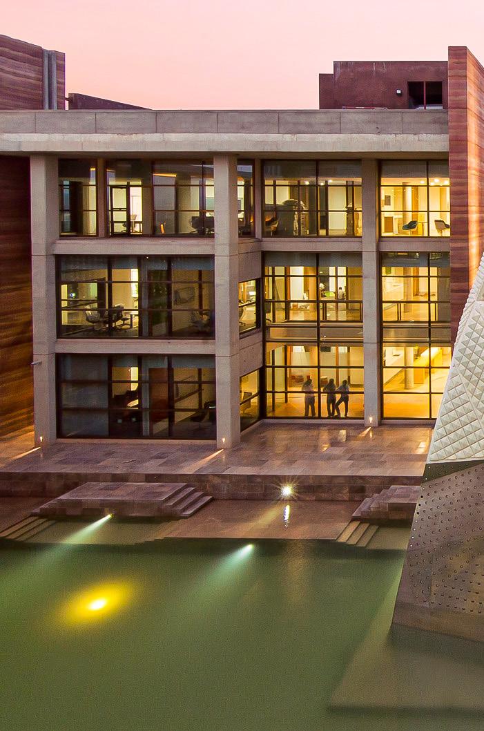
The Telenor Campus creates a distinct architecture which is planned around step wells; woven together through an internal street which changes in width and volume as it staggers around the complex.
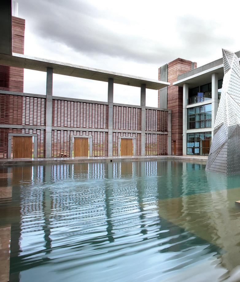
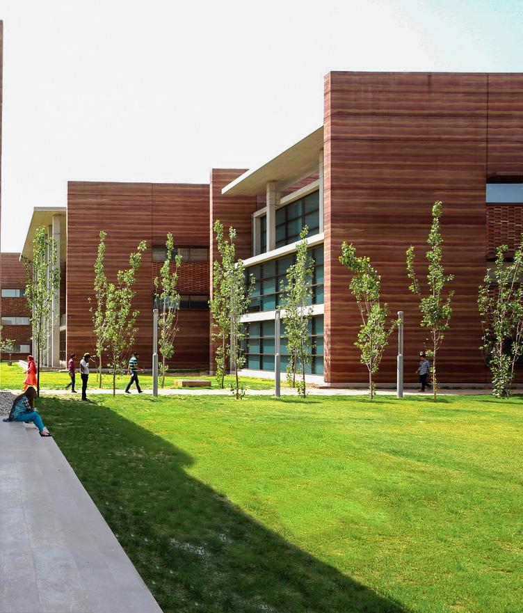
Traditionally, courts have always played an integral part in local architecture, be it residential, institutional or religious building types. These central spaces become the main socializing hubs for the workforce.
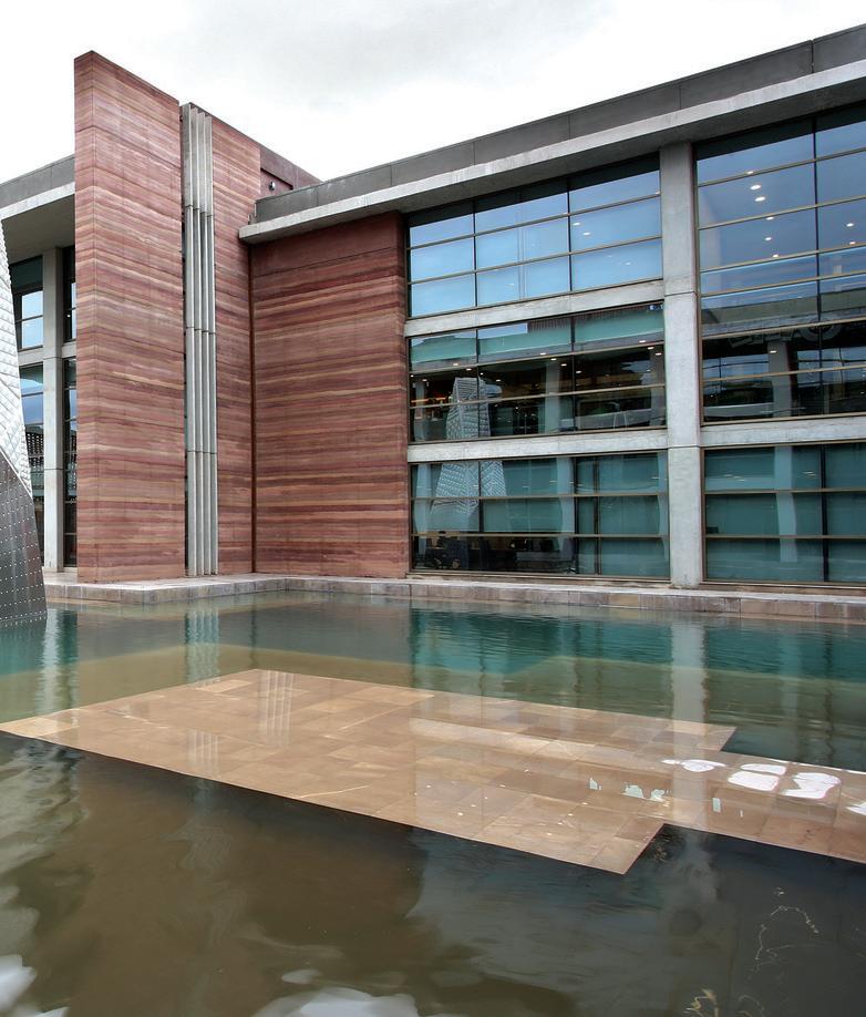
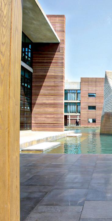
In Telenor’s campus, this concept is used as a focal point, interconnecting blocks around large water bodies in the internal courts to encourage social interaction between the users.
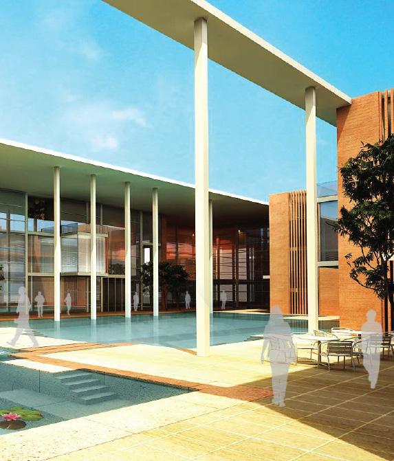
Located in Islamabad, Pakistan, the site for the Telenor campus is made up of 15 acres of an undulating landscape which exemplifies the Potohar plateau region, where this area is geographically located.
The design ensures that the site’s existing topography and natural water courses remain intact: for this, inspiration was sought from the historic step wells of Pakistan’s Punjab province, used as an architectural device for storing rainwater, also known as Baolis.
1 WORK ZONES
2 RECEPTION
3 MULTIPURPOSE HALL
4 ATRIUM
5 CAFETERIA
6 DAY CARE
7 MULTISTORY PARKING
8 SCULPTURE GARDEN
9 CITRUS GROVE
The plan is for an open space office environment divided into 5 work zones (shown in different colors) with a water body in the center of the structure. A bridge connects both sides.
Much of the contoured landscape was left untouched. A number of different species of trees were planted to enhance the landscape as the importance of the surroundings in creating a conducive work atmosphere was taken into account.
In addition, a sculpture garden was also situated within the landscape to provide a different sort of refuge from the office environment. These elements are complemented by the natural stream running along the boundary wall.
The circulation corridors and the meeting rooms overlook the central water bodies. The main street connects the work areas with meeting rooms, social zones and breakout spaces, all of which combined become the main zone of communal activity which lies between the outdoors stepwell area and the indoor work environments.
All these zones weave in and out of each other providing multiple opportunities for work, interaction, collaboration and social activity. The main street is present on every floor and forms a central element in the design of the structure, bringing everything together.
MAIN STREET
OPEN OFFICE WORKZONE
UTILITIES
CONFERENCE ROOMS
SILENT ROOMS
MEETING ROOMS
SOCIAL ZONE
The Ground and First floors are duplicated in certain workzones, whereas the second floor includes terraces, which are present on both north and south sides to take advantage of the splendid views on offer at the site.
The opposing sides of the campus are connected by a bridge which offers opportunities for people from various departments to meet as they pass by each other during the course of the day.
Solar panels are also installed on the roof to generate power for the
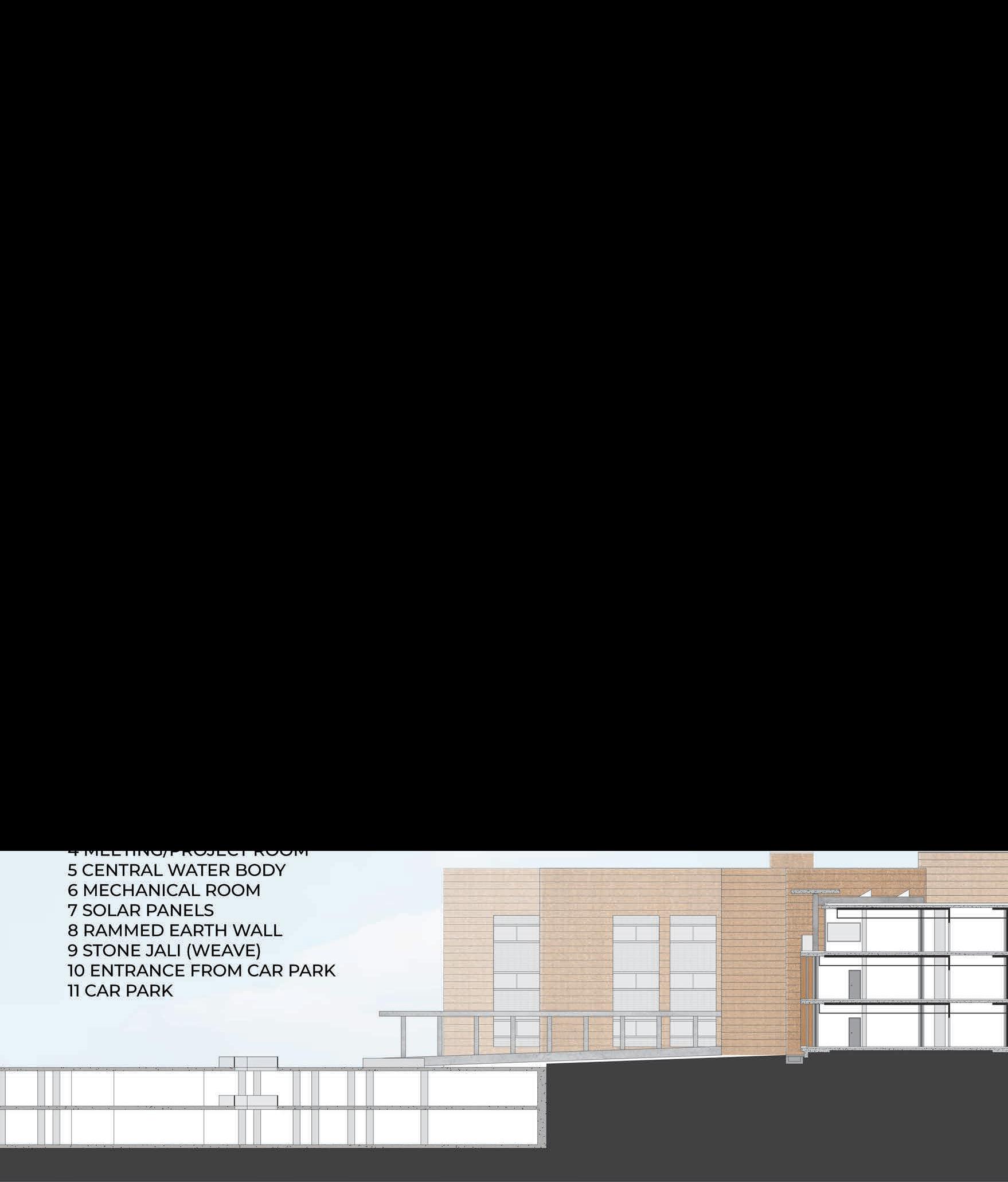
1 TERRACE
2 WORKZONES
3 UTILITY ROOM
4 MEETING/PROJECT ROOM
5 CENTRAL WATER BODY
6 MECHANICAL ROOM
7 SOLAR PANELS
8 RAMMED EARTH WALL
9 STONE JALI
10 ENTRANCE FROM CAR PARK
11 MULTI LEVEL CAR PARK
building. The rammed as well as concrete thermal capacity, ensuring energy requirements
Other sustainability include rain water low flow fixtures in occupancy sensors.

rammed earth material have a high ensuring reduced requirements for the campus. sustainability mechanisms harvesting and in addition to sensors.

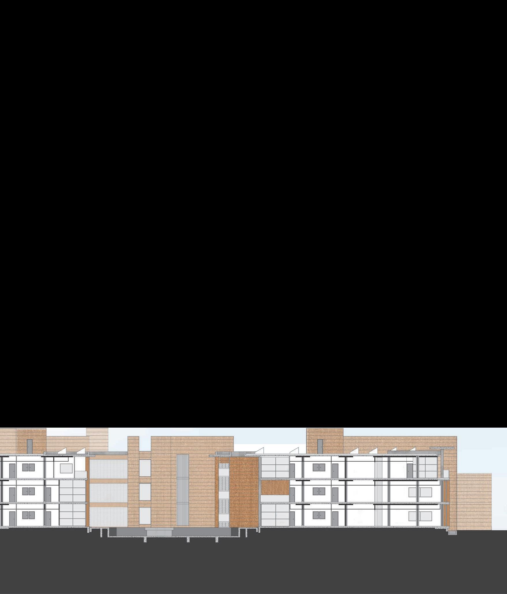
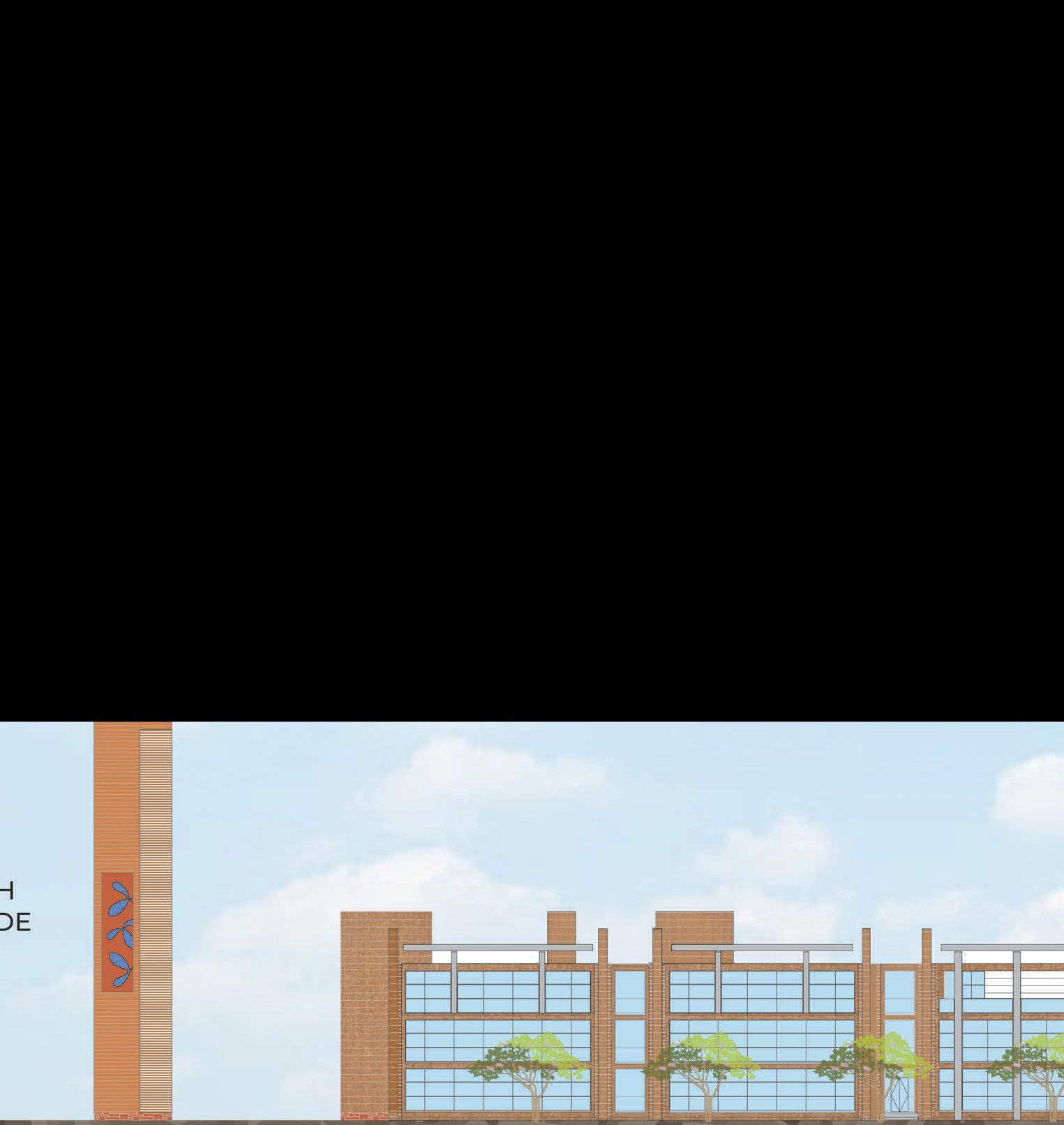
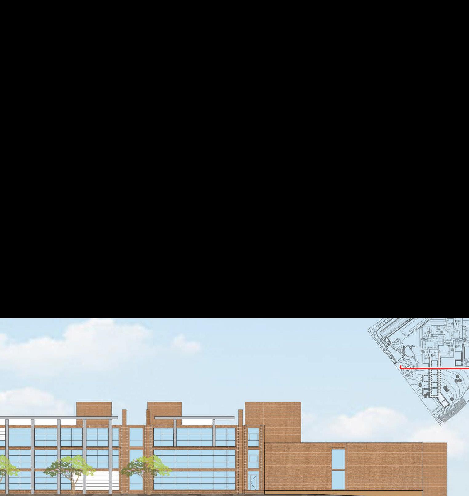
Conceptually the block orientation is kept in the North-South direction to minimize heat gain. In this regard, the insulated stabilized rammed earth flank walls have been placed in the East-West directions with minimum openings.
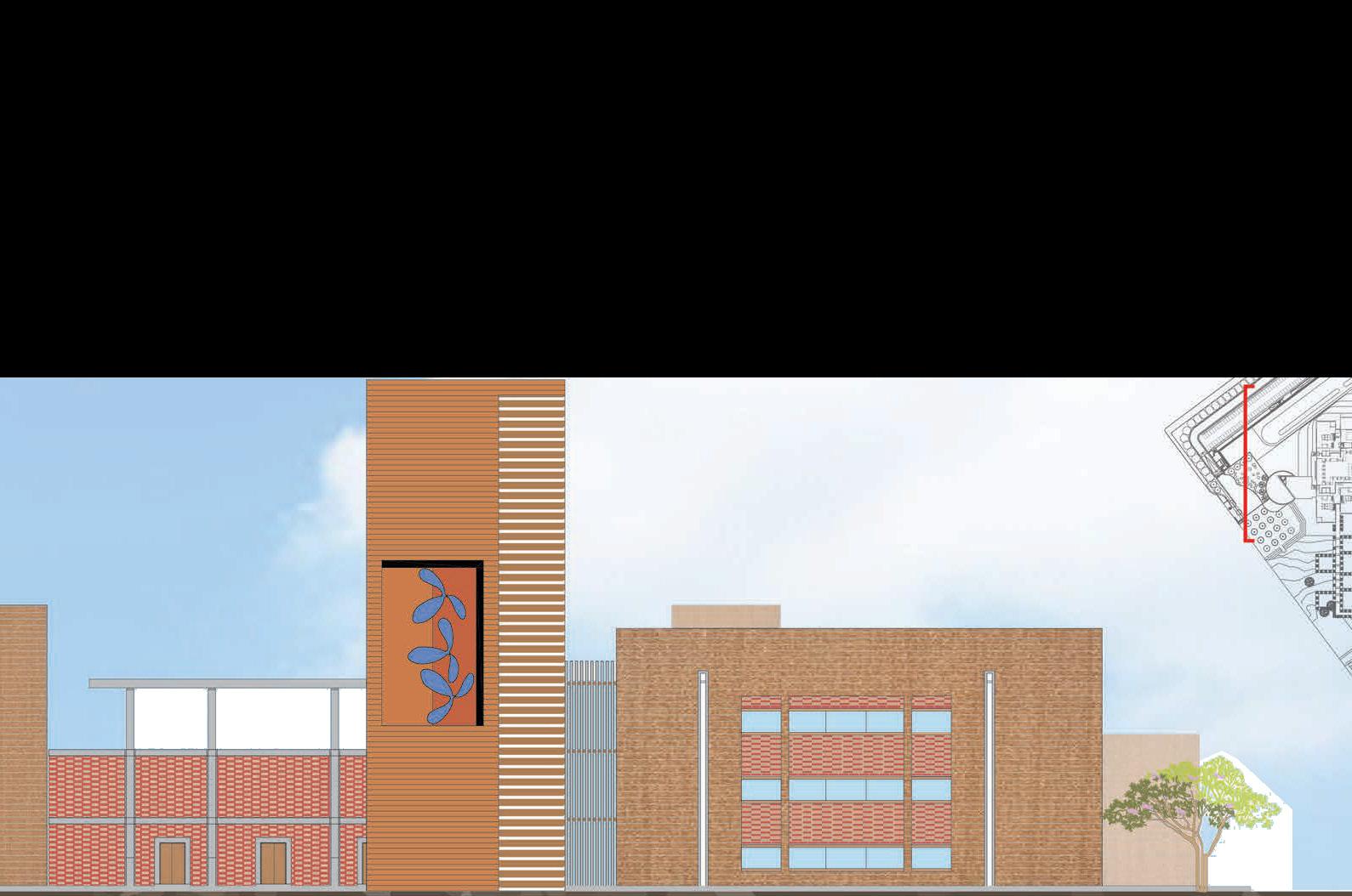
The expression of materiality is celebrated through the use of fair-face concrete, rammed earth and local stone.
The stabilized rammed earth walls strongly depict the natural hues of the Potohar Valley soil belonging to this area. The conversation continues in the internal courts with the use of local stone in the step wells and ‘Jaali’ screens which filter the harsh summer sun.
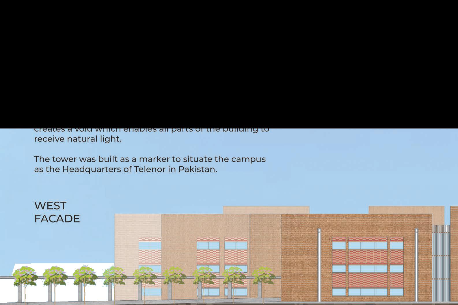


Generous windows have been placed on the north-south direction to allow indirect light to penetrate the campus. The water body in the middle creates a void which enables all parts of the building to receive natural light.




Philharmonie
AS 3200
Instructors:
Maxi Spina, Randy Jefferson
Partners:
Aseel Alamoudi, Bashayer Bamohsen, Kovarthini Sekar
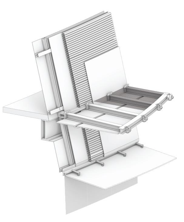
A course studying material and tectonic qualities of facades and envelopes; an investigation of how structural systems work as an integrated system to realise a project.
Case Study:
Philharmonie de Paris by Atelier Jean Nouvel.
Philharmonie de Paris, transformed
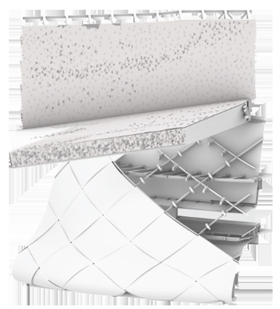
Detail A2
Detail A1
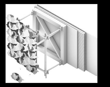
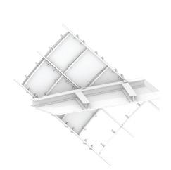
Structural frame (primary support)
Stainless steel frame fastener with bolted connection (secondary support)
Support grid for facade
Sealing membrane
Insulation
Support Plate
Aluminium bird tiles
Screw connecting tiles to grid
Aluminium bird tiles
Structural steel welded rectilinear frames
Aluminium Panel
Double profile forming edge of the demountable trunks of braided venture beam
Structural Steel welded transition frames
Philharmonie de Paris, transformed
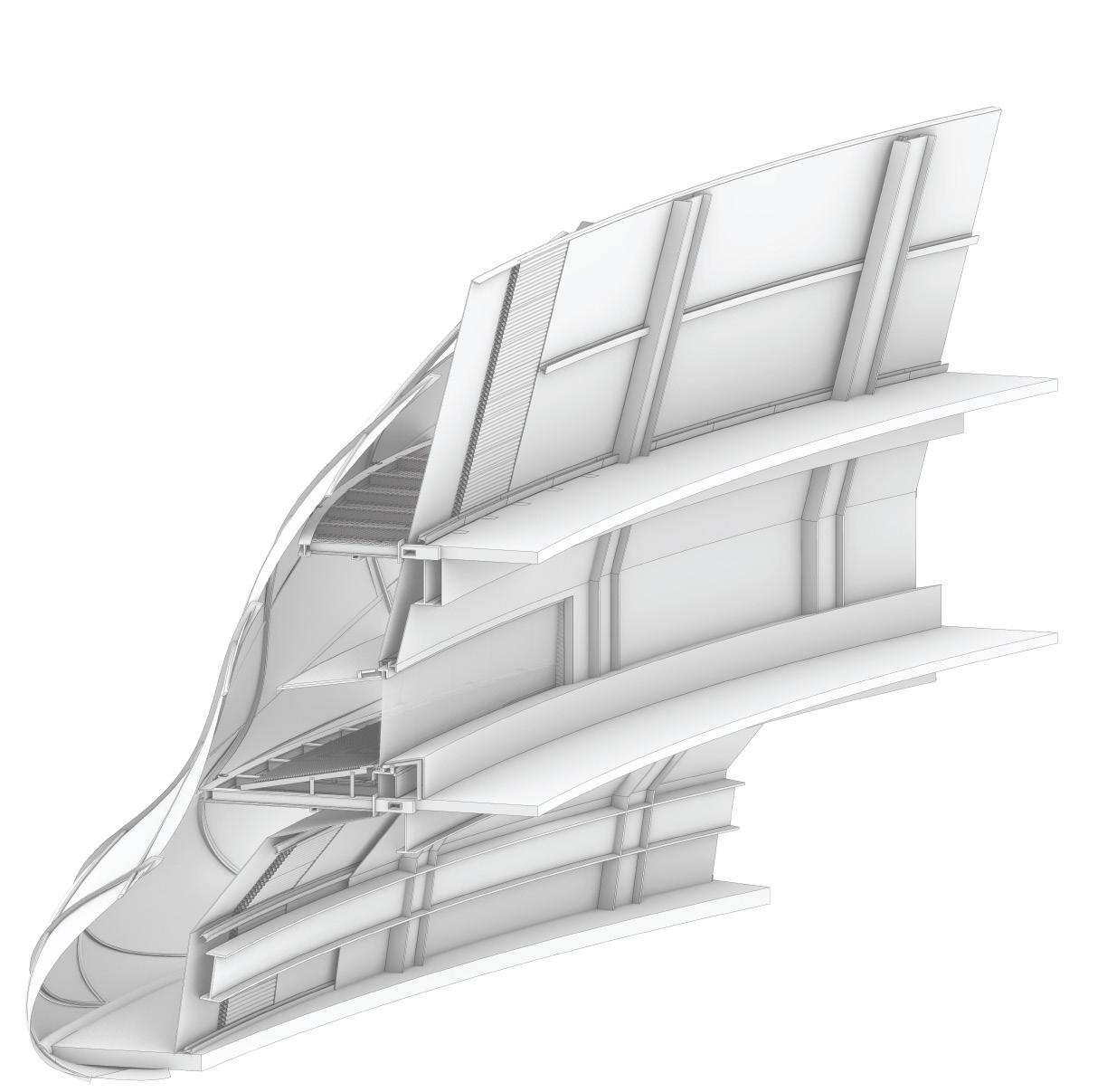
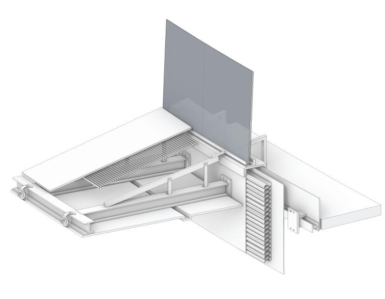
Waterproof Membrane
Rock Wool Insulation
Aluminium Plate
I-Section Column (vertical support)
Double Plaster
Braided SS mesh on Metal Stretch
I-Section Beam (horizontal support)
Running Profile 180mm x 100mm
Double profile forming the edge of the demountable trunks of braided venture frame
Connecting rod IPE 220- horizontal support of the braided venture frame
CF90 min (panel type) fibre cement by connecting rod
Frame of parallel bars holding together
Interior wall - coating of woven mesh
Double glazing insulating film on high joinery and base silicone vertical seal
High bead arch with high seal
Galvanised steel interior and vapor coated
Frame of parallel bars
Double plaster
Spinning frame profile facade
Candle support rod
150mm thick plates
Waterproof Membrane
Threshold of maintenance - braided SS mesh on metal stretch Rock wool insulation

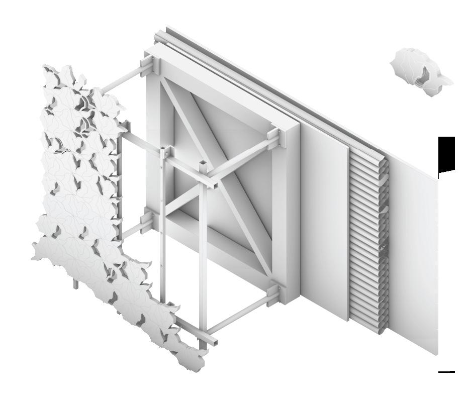
Aluminium and Glass Tiles
Connecting Grid
Structural Grid
Waterproof Membrane
Insulation
Supporting Sheet
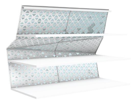
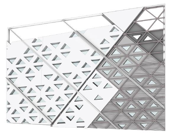
Our objective was to transform the tectonic qualities of the facade. Our changes are as follows:
1. We replaced metal bird tiles at the top periodically with glass tiles to change the aesthetic (A5).
2. We changed the shape of the front to a linear contemporary one, while also making it almost 50% transparent to let natural light flood into the main hall of the project.
3. We defined these two changes by changing the cantilever from metal tile to concrete, thereby using materiality to refocus attention to our transformation.
Philharmonie de Paris, transformed
Steel Frame
Waterproof Membrane
Interior Finishing
Insulation
Joint between panels
Glass Frame
Exterior Finishing
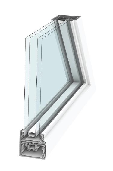
Vision Glass
External Weep
Glass Spacer
Setting Block
Thermal Break
AS 3222
Instructors:
Herwig Baumgartner, Matthew Melnyk
Group:
Shuo Feng
Carnation Kng
Ahmad Sultan
Kyle Balster
Zhaoqi Zhu
Rene Perez Ignacio
Jordan Scheurmann
Aseel Alamoudi
Jinyu Rao
Heena Patel
Hsiang Wang
Mitsuki Ikeda
Objective:
To take a design developed by one of our student studio teams at Sci ARC and figure out how it will come together and be constructed in the real world.
Program: A design for LACMA by Mitsuki Ikeda and Zhaoqi Zhu.
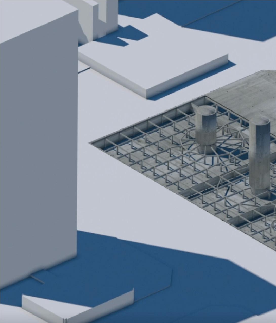
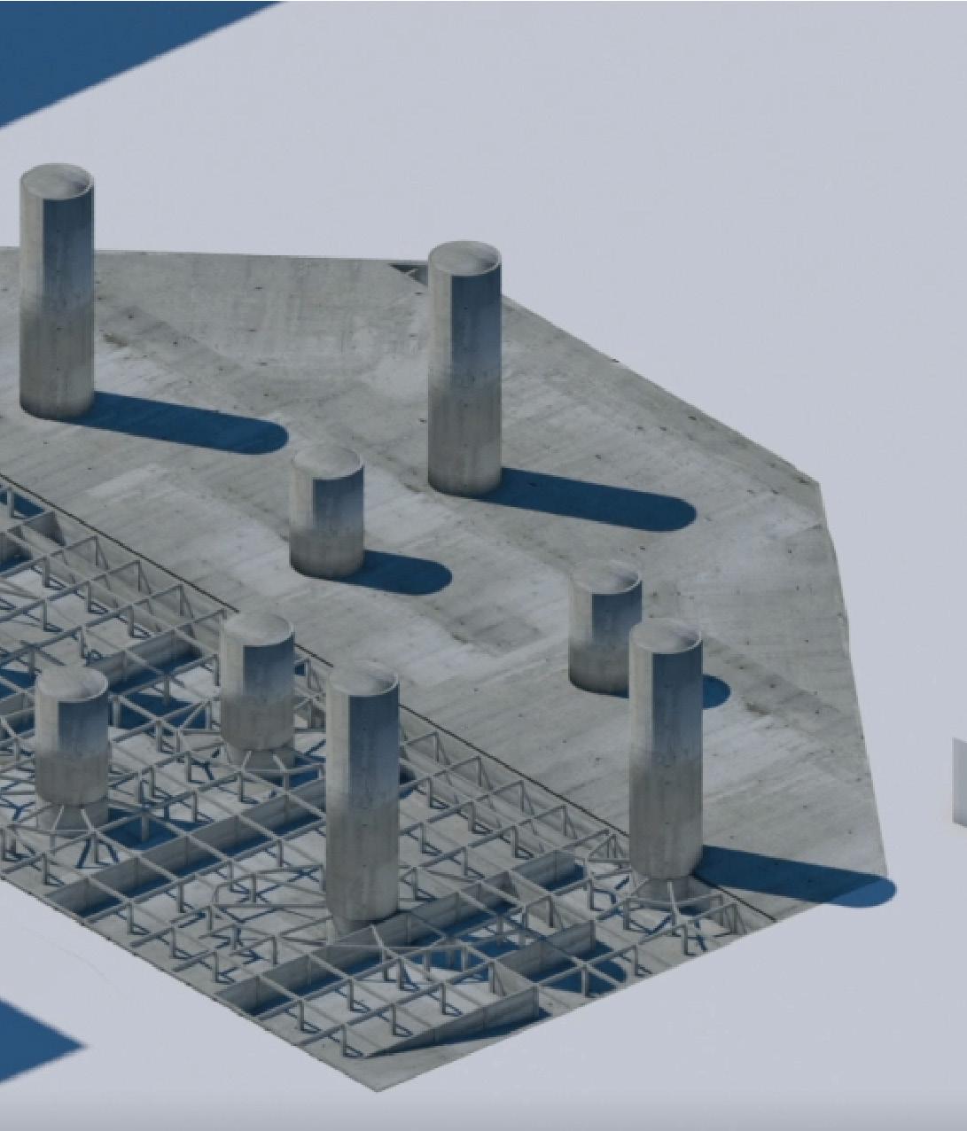
1) Site excavation and debris clearing
2) Soldier piles at site boundary
3) Concrete shoring between piles
4) Basement level concrete poured
5) Basement level walls and columns poured
6) Basement level core members poured
7) Horizontal beam members placed
8) Core members poured for remaining levels
9) Ground level concrete poured
Egg crate transverse beam connection detail sequence:
1) Pilot threading
2) Steel plate
3) Fasteners
4) I-Beam
5) L-bracker joint
6) Fasteners
7) Perimeter I beam
8) Fasteners
9) Steel Plate
10)Fasterners
11) U-Bracket Joint
12) Egg Crate
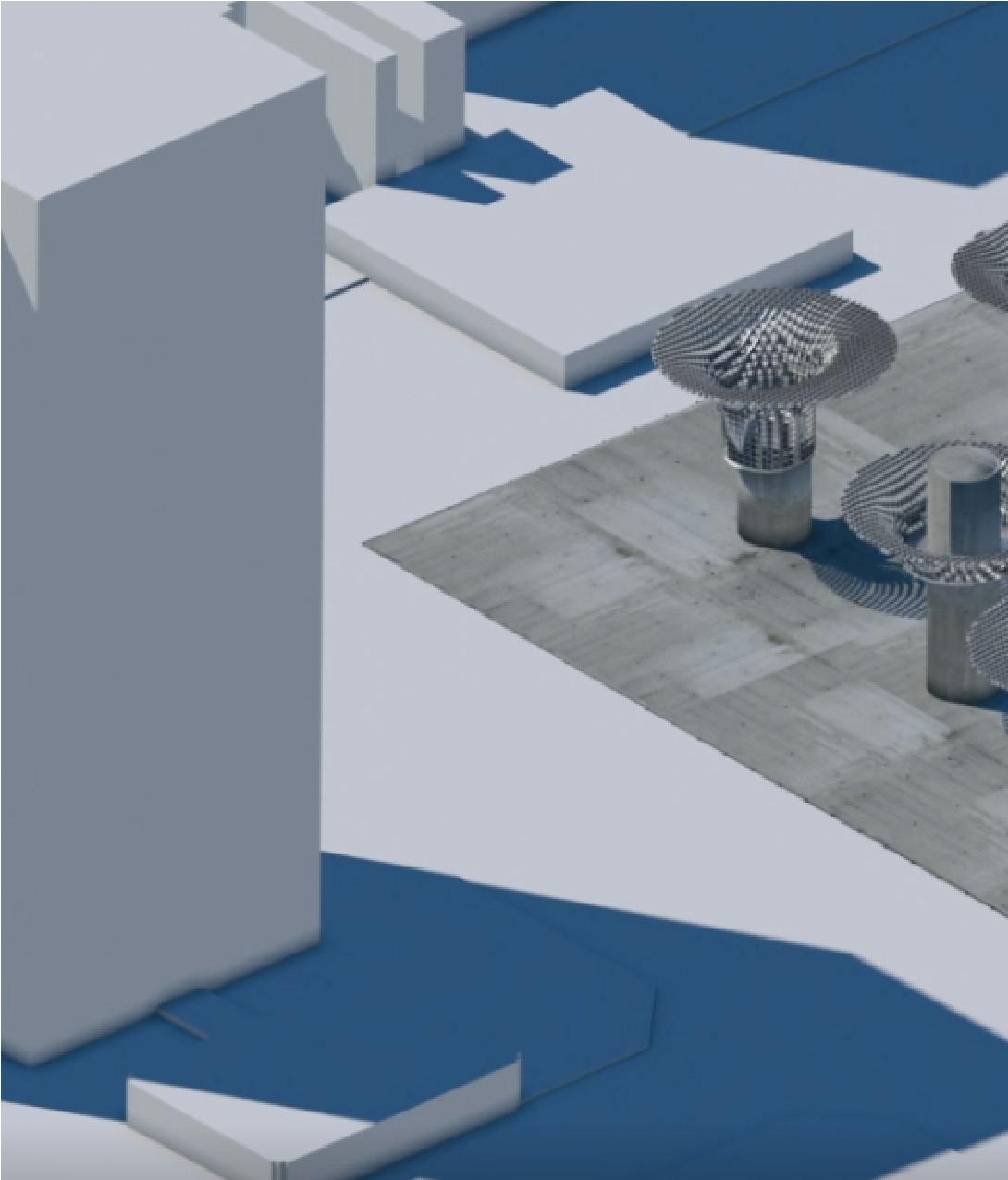


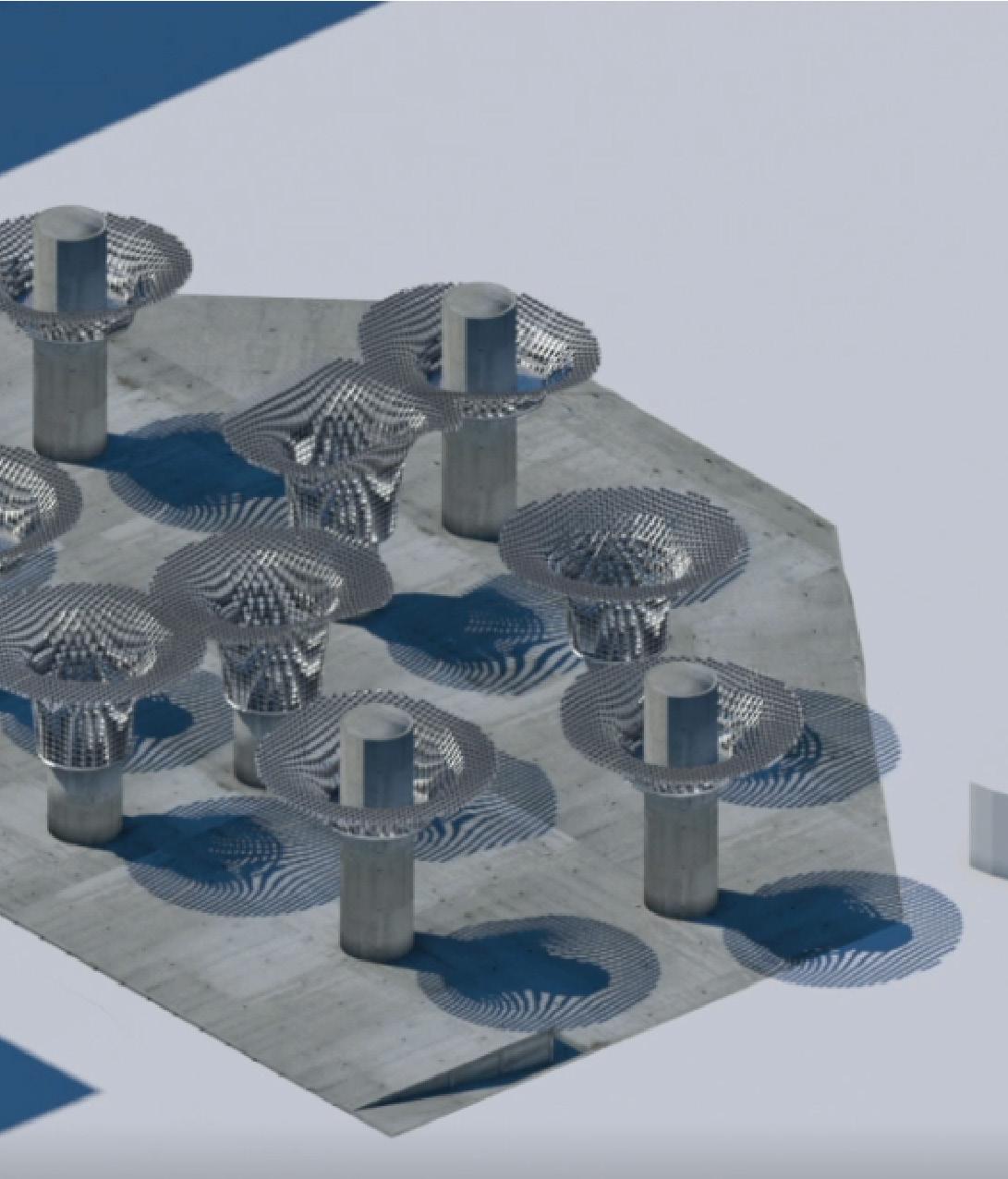
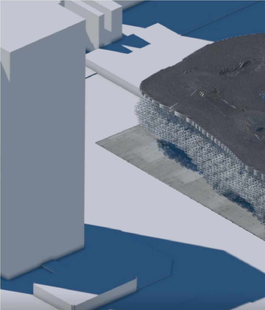
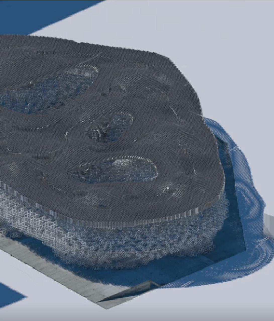
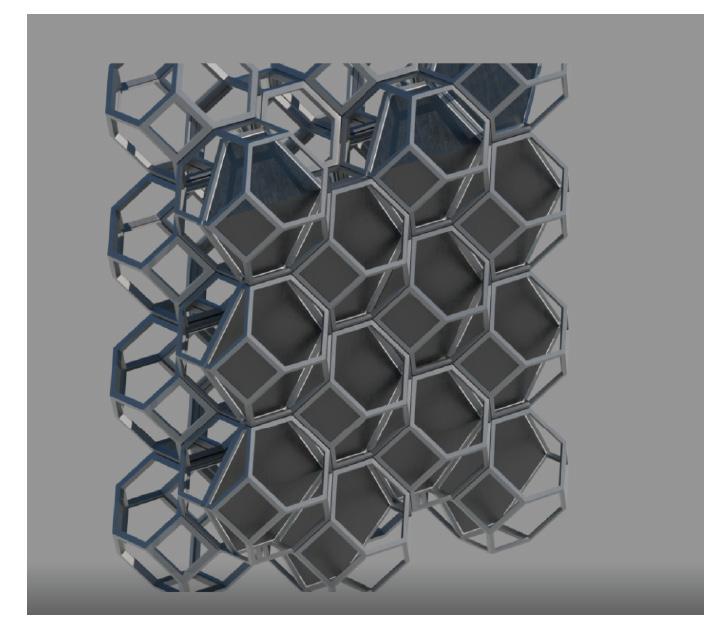
After egg crate is fixed in place the facade consisting of modular metal polygons is fixed in place and the remaining floors poured.
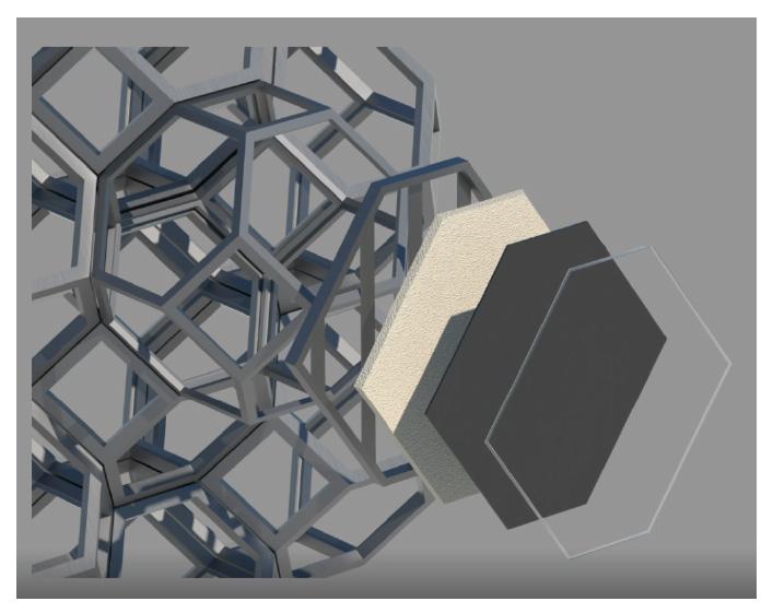
Rigid Insulation
Waterproofing membrane
Silicon beading
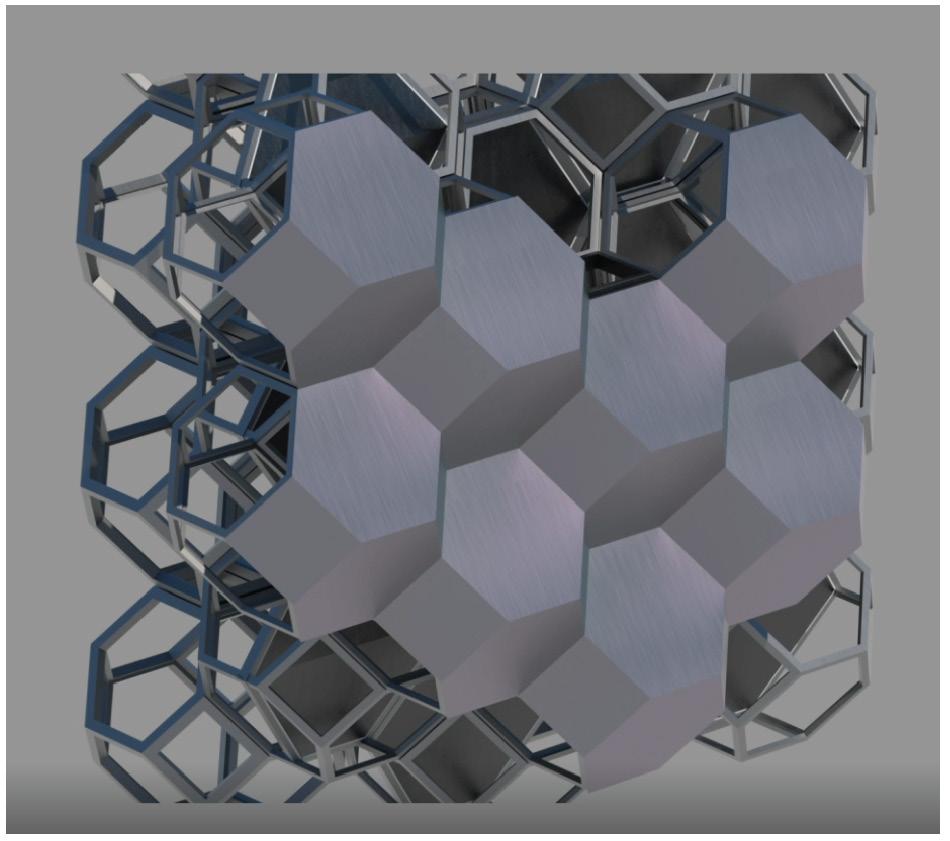
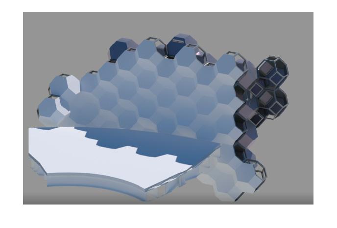
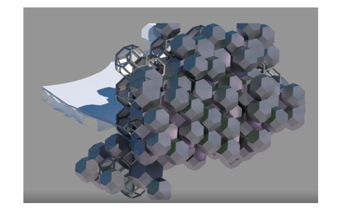
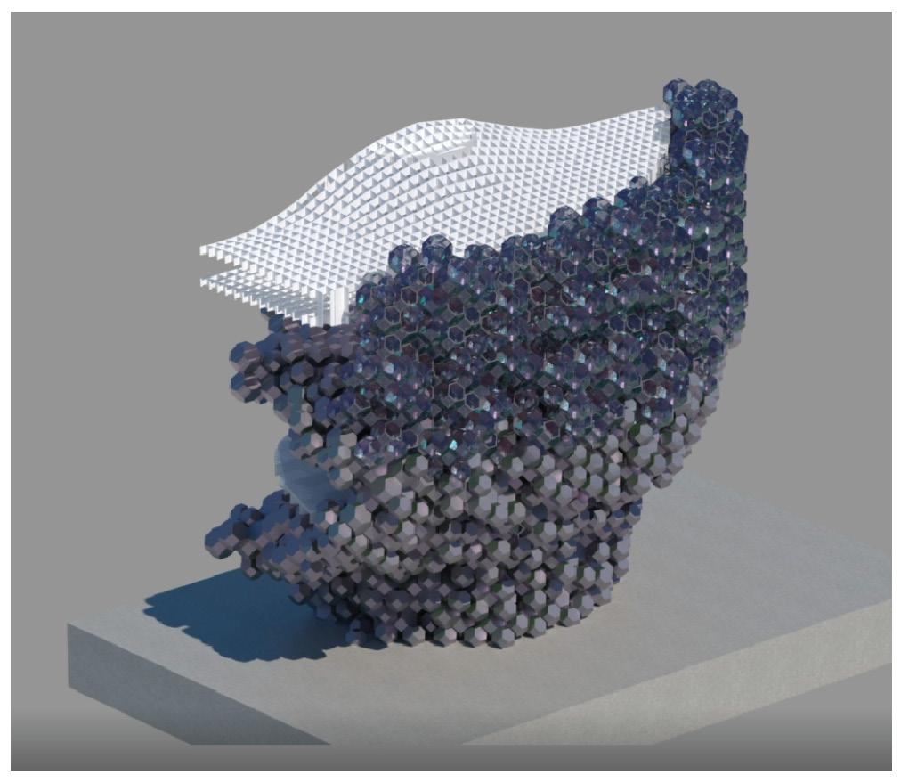
Modules are connected with fasteners and connection members and covered with a Titanium facade
Unified Waterproofing Layer
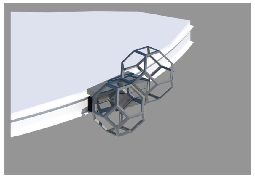
Sequence:
1) Steel Tube skirt
2) Steel plate
3) Facade system
4) Steel plate
5) Fasteners
6) Floor covers


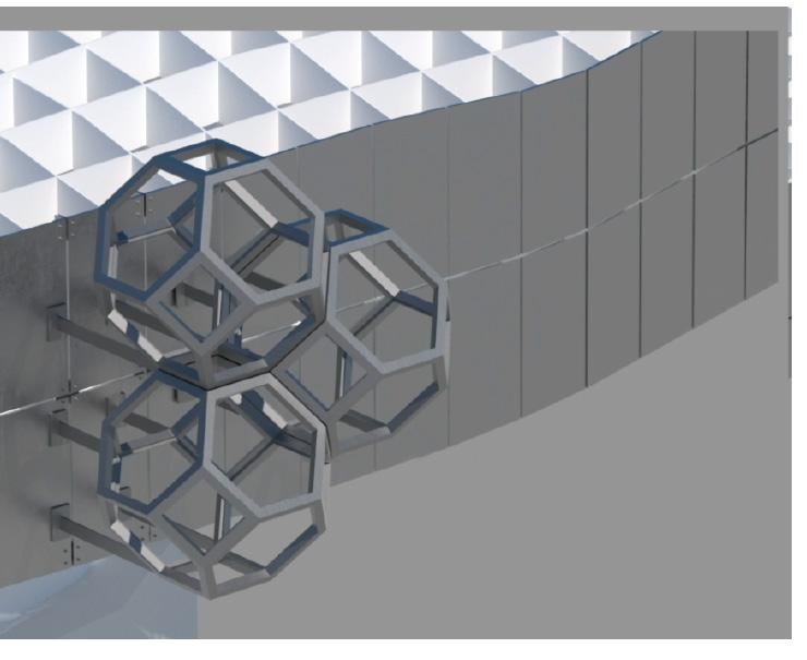
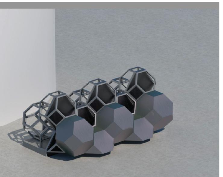
Sequence:
1) Steel plating
2) Steel connections
3) Facade system
Sequence:
1) Concrete curb
2) Steel flashing
3) Steel plate
4) Structural facade
5) Secondary facade
6) Fasteners
Aesthetic facade

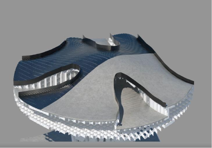
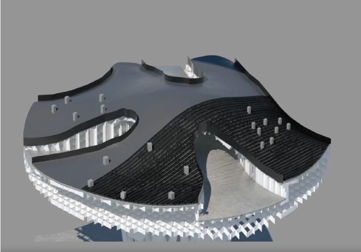
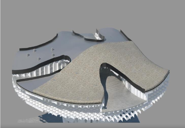
Waterproofing membrane and Protection Mat
Planter concrete pedestals
Drainage
Filter Sheet
Growing Substrate
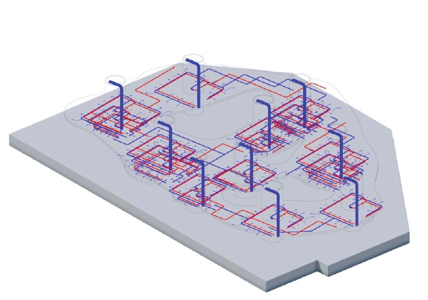
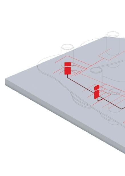

Water
Municipal Supply
Grey Water
