

www.aspoeck.com


2 24V OEM PRODUCT CATALOGUE GENERAL 04 Introduction 08 The system WIRING & JUNCTION BOXES 92 Feed line 94 Main cable 95 Side marker lamp wiring 96 Junction box & wiring LAMPS 13 Rear lamps 42 Position lamps 56 End-outline marker lamps 62 Number plate lamps 68 Number plate holder 74 Work & reversing lamps 78 FlexLED LED strips & interior lamps
3 www.aspoeck.com ACCESSORIES 102 SMCG - Side Marker Control Gear 104 ERD - Electronic Reversing Device 105 Reversing alarms 106 LCG - LED control gear 108 RDC - Ramp Distance Control Premium 110 RADC 1.0 - RADAR Distance Control 1.0 112 Smartlink 114 Expansions 115 Contour markings 116 Underrun protection WIRING SOLUTIONS 120 Standard wiring with SMCG 121 Standard wiring with flashing side marker lamps MOUNTING REGULATIONS APPENDIX 124 Rear lighting 128 Side lighting 129 Front lighting 132 Plug-in diagram 135 Pictogram overview CONTENTS
Individual systems – satisfied customers. Since its founding in 1977, Aspöck Systems GmbH has focused on a philosophy that has made it one of the leading manufacturers in the field of lighting for the automotive industry today: The development of customised solutions for each individual customer. This flexibility is the reason for the success of Aspöck systems.
Innovative products. We see it is our obligation to create state of the art wiring and lamps, and as pioneers in this field, to also set standards. We rely on waterproof cable and plug-in systems and LED lighting for all areas of application.
Continuous growth. We have been continuously expanding our main plant in Peuerbach, Upper Austria, in recent years to include production, storage and administration areas. Every year we invest in new production facilities and test and development equipment, which is how we remain at the cutting edge of technology. At the same time, we continue to educate and train our employees in order to always be able to give you the right answer, even with more difficult questions, for example questions surrounding special regulations.

4 24V OEM PRODUCT CATALOGUE
WE BRING THE LIGHT TO THE STREETS

5
FROM THEN TO NOW
AND ON INTO THE FUTURE...
Completion of the first Aspöck ”Multipoint” lamp ´96
Aspöck was founded for the production of lighting for agricultural vehicles
´77
Aspöck Germany was founded ´88
Development of the first Aspöck plug-in system
Construction of the production facility in Peuerbach
´82
New customers: Caravan Manufacturers
´91
Production site extension in Portugal ´11
New customers: Truck trailer manufacturers ´92
Takeover of Fabrilcar
New customers:
Motorcycle manufacturers ´07
Commissioning of automated high-bay warehouse in Peuerbach
´09
Change of company name from Fabrilcar to Aspöck Portugal
´08
Aspöck Poland was founded ´12
New office building
Peuerbach
ECOLED II rear lamp
ASPÖCK LumEU ´18
6 24V OEM PRODUCT CATALOGUE
´81
Aspöck UK was founded
Aspöck France was founded Aspöck do Brazil was founded ´01
Aspöck Iberica was founded ´99
New customers: Bicycle rack manufacturers
´97
“Europoint III” The first lamp with “Light Guide” for trailers
Aspöck Turkey was founded ´13
New customers: LKW manufacturers Aspöck Norden was founded ´05
Introduction of overmoulding technology for connectors ´04
Participation PAGG Aspöck ´03
Production site extension in Portugal
´15
New customers car manufacturers ´06
New office and logistics building French site
´17
Opening of Polish production site
´16
Expansion of incoming goods department and picking warehouse Site: Peuerbach
Expansion of Polish automotive production site
AgriLED I & AgriLED II first agricultural rear lamps
´20
7 www.aspoeck.com
´19 ´22
THE ASPÖCK CONNECTOR SYSTEM
The Aspöck connector system consists of 2-, 3-, 7- and 17-pin plug and socket housings. Each of these wiring systems can be used individually for all 24 V trailers. Aspöck connector systems allow easy connection to all components. All connectors are overmoulded and tested according to protection classification IP69K (jet-proof and submersible).
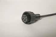
3-pin ASS3 plug
IP 6K9K
The 3-pin ASS3 connector enables easy and flexible mounting due to its small diameter. The ASS3 can also be used for additional 3-pin functions.
17-pin ASS3 plug
IP 6K9K
The 17-pin plug and socket housings connect the front supply, main cable and rear wiring as well as ensure easy integration of an additional distributor.
7-pin ASS2 plug
IP 6K9K
Aspöck rear lamps are connected to the Aspöck connector system by the 7-pin plug. These 7-pin plug and socket housings can of course be used for other additional functions.
2-pin ASS2 plug


IP 6K9K
The 2-pin ASS2 plug is an advancement of the 2-pin ASS1 plug – the advantage for you is an additional bayonet lock. This enables quick and safe connection of e.g. navigation lights, side marker lamps and end-outline marker lamps as well as additional 2-pin functions.
Press & Ready system I P&R
IP 6K9K
The P&R wiring system is another contact option characterised by quick and uncomplicated mounting on the vehicle. All Aspöck single-function lights can be equipped and connected with the P&R system.
The cables are supplied in different lengths according to requirements. These lamps can be mounted in a 2-core flat cable at any point and are already tested for function. They are totally waterproof due to silicone single-core sealing and may also be used in the transportation of hazardous goods.


8 24V OEM PRODUCT CATALOGUE
Other connector systems

In addition to the Aspöck connector system, the Aspöck Group offers a wide range of standard connector systems which are available from stock, meaning we can offer maximum flexibility.


9 www.aspoeck.com
AMP 4 / 7-pin
Superseal
2 to 6-pin
Deutsch
2 to 8-pin
HDSCS
2 to 18-pin
DEUTSCH 2 pin Imax=13A 16 31 2 1 FREE 16
DEUTSCH 2 pin female
LIGHT SYSTEM
Aspöck lets you shine
The production of the entire light system ensures that all Aspöck components – first and foremost the lamps, but also the accessories (LCG, SMCG), the junction boxes, etc. – can be perfectly interconnected, guaranteeing maximum reliability (up to ADR and IP6K9K).

Feed lines Page 92
Side marker lamps
Page 42
Main cable Page 94
Junction box Page 96
Supply harness Page 99
Rear lamps
Page 13
End-outline marker lamps Page 56
10 24V OEM PRODUCT CATALOGUE
FlexLED LED strips & interior lamps
Page 78
3rd stop lamps
Page 82
Position lamps
Page 42
SML supply
Page 95
Side Marker Control Gear
Page 102
Underrun protection
Page 116
Number plate lamps
Page 62
Work & reversing lamps
Page 70
11 www.aspoeck.com
REAR LAMPS
3-CHAMBER LAMP
ECOLED
ECOLED II
MULTILED III
EUROPOINT III
BRASPOINT 140
NUMBER PLATE LAMPS
BEACONS INTERIOR LAMPS
WORK LAMPS
NUMBER PLATE HOLDERS
SIDE MARKER LAMPS
REVERSING LAMPS
BRAKE LIGHT
REAR LAMPS POSITIONS LAMPS
END-OUTLINE MARKER LAMPS
NUMBER PLATE LAMPS
BEACONS
INTERIOR LAMPS
LAMPS
NUMBER PLATE HOLDERS
12 24V
PRODUCT
OEM
CATALOGUE
Aspöck Systems stands out ot only for its many wiring solutions, but also its wide range of rear lamps. The quality of the products is of top priority, meaning all light lenses are resistant to chemicals, acids and scratches.

ECOLED III
The 5-function light from Aspöck Systems
END-OUTLINE MARKER
REVERSING LIGHT
DYNAMIC DIRECTION INDICATOR
PRODUCT FEATURES
INCREASED VISIBILITY
Large Glowing Body light surfaces
REAR LIGHT CROSS-CIRCUIT
Increased safety due to separate supply of the rear light

DYNAMIC DIRECTION INDICATOR
Sequential directional indicator function
ISO PULSE CAPABLE
Direction indicator failure monitoring according to ISO 13207-1
OPTIONAL CONNECTIONS
The option of four additional 2-pin connections on the rear of the lamp
INTEGRATED SMCG (Side Marker Control Gear)
Control for flashing side marker lamps
OUTLINE MARKER WITH PREDETERMINED BREAKING POINT
In the event of damage, only the mounting bracket needs to be replaced
HIGH IP CLASS IP6K9K
Pressure and water resistant
14 24V OEM PRODUCT CATALOGUE REAR LAMPS
ADR Zone 2 ISO 13207-1
IP 6K9K STOP LIGHT FOG LIGHT TAIL LIGHT 1
TAIL LIGHT 2


15 www.aspoeck.com PART NO. PART NO. 24V V ADDITION CONNECTION 25-4123-017 25-4122-017 1/- LED 24 V 7-pin ASS2 25-4123-027 25-4122-027 1/- LED 24 V 7-pin ASS2 4 x 2-pin ASS2 25-4123-037 25-4122-037 1/- LED 24 V LED 7-pin ASS2 2 x 2-pin ASS2 25-4123-047 25-4122-047 1/- LED 24 V 7-pin AMP 25-4123-057 25-4122-057 1/- LED 24 V 7-pin AMP 4 x 2-pin Superseal 25-4123-067 25-4122-067 1/- LED 24 V LED 7-pin AMP 2 x 2-pin Superseal
TRAILERVersion F D B 2 4 6 8 1 3 5 7 2 4 6 8 1 3 5 7 E C A F D B E C A A3 - AutoCAD 2019 CP_03-0_Zeichnungsblatt Beschreibung Leidinger Sabine 2022/08/16 \\at-sys-fscomp\AT\Technik-Allgemein\_ProduktZeichnungen_fuer_Marketing\25-4123-017_EcoLED_III.dwg (152) Marketing Seite 1 (45) (380) (570) (140)
WITH OUTLINE MARKER Version
ECOLED II
DYNAMIC DIRECTION INDICATOR
END-OUTLINE MARKER
PRODUCT FEATURES
LENS REPLACEABLE
Only one replacement lens, which can be used for the left or right side
CAN BE USED ON BOTH SIDES
Rear lamp rotates 180 degrees – use left or right

OUTLINE MARKER WITH PREDETERMINED BREAKING POINT
In the event of damage, only the mounting bracket needs to be replaced
DYNAMIC DIRECTION INDICATOR
Flashing light function as sequential light
INCREASED VISIBILITY
Large light surface + homogeneous light pattern
ISO PULSE CAPABLE
Direction indicator failure monitoring according to ISO 13207-1
INTEGRATED SMCG (Side Marker Control Gear)
Control for flashing side marker lamps
DUAL VOLTAGE
For 12 & 24 volt applications
16 24V OEM PRODUCT CATALOGUE
REAR LAMPS
IP 54 ADR Zone 2 ISO 13207-1
Full LED rear lamp with Glowing Body technology
STOP LIGHT
FOG LIGHT TAIL LIGHT REVERSING LIGHT


17 www.aspoeck.com
Version TRUCKVersion PART NO. PART NO. 24V V VERSION ADDITION CONNECTION 25-4121-007 25-4120-007 1/8 LED 12V 24V 7-pin ASS2 25-4121-017 25-4120-017 1/8 LED 12V 24V 7-pin ASS2 4 x 2-pin ASS2 25-4121-027 25-4120-027 1/8 LED 12V 24V LED 7-pin ASS2 4 x 2-pin ASS2 25-4121-037 25-4121-037 1/8 LED 12V 24V 7-pin AMP 25-4121-047 25-4120-047 1/8 LED 12V 24V 7-pin AMP 4 x 2-pin Superseal 25-4121-057 25-4120-057 1/8 LED 12V 24V LED 7-pin AMP 4 x 2-pin Superseal 25-4121-067 25-4120-067 1/8 LED 12V 24V 7-pin AMP F D B 2 4 6 8 1 3 5 7 2 4 6 8 1 3 5 7 E C A F D B E C A A3 - AutoCAD 2019 / CP_03-0_Zeichnungsblatt Beschreibung Leidinger Sabine 2022/11/17 \\at-sys-fscomp\AT\Technik-Allgemein\_ProduktZeichnungen_fuer_Marketing\25-4121-007_EcoLED_II.dwg Marketing Seite 1 (152) (360) (550) (46.5) (146) RFS/31 58L/31 58L/31 SMCG out LABEL Trailer - Version Truck - Version
TRAILER
EUROPOINT III
END-OUTLINE MARKER
SIDE MARKER LIGHT & REFLECTOR
Europoint III FULL LED Europoint III Truck PRODUCT FEATURES
FIBRE OPTIC TECHNOLOGY
Rear light as “light guide” for a distinctive design
FLEXIBLE OUTLINE MARKER
REVERSING LIGHT
TAIL LIGHT
Option for direct mounting of an additional flexible LED end-outline marker lamp
OPTIONALLY INTEGRATED SMCG (Side Marker Control Gear)
Control for flashing side marker lamps
OPTIONAL CONNECTIONS
Optionally with four additional 2-pin connections on the rear of the lamp
FULL LED + LCG
Option of full LED rear lamp including direction indicator LCG
LIGHT BULB + LED CAN BE COMBINED
Functions in light bulb and LED hybrid technology
LED REAR POSITION LAMP
As standard

18 24V OEM PRODUCT CATALOGUE
REAR LAMPS IP 56K ADR Zone 2
DIRECTION INDICATOR
LIGHT FOG LIGHT
STOP
Multi-chamber lamp with distinctive fibre optic technology


19 www.aspoeck.com
Version
PART NO. PART NO. 24V V VERSION ADDITION CONNECTION 25-7000-507 25-7400-507 1/10 24 V 7-pin ASS2 25-7000-517 25-7400-517 1/10 24 V 7-pin ASS2 4 x 2-pin ASS2 25-7020-507 25-7420-507 1/8 24 V LED 7-pin ASS2 25-7020-517 25-7420-517 1/8 24 V LED 7-pin ASS2 4 x 2-pin ASS2 25-7000-707 25-7400-707 1/10 LED 24 V 7-pin ASS2 25-7020-737 25-7420-767 1/8 LED 24 V LED R LCG 7-pin ASS2 25-7000-717 25-7400-717 1/10 LED 24 V 7-pin ASS2 4 x 2-pin ASS2 25-7020-707 25-7420-707 1/8 LED 24 V LED 7-pin ASS2 25-7000-747 25-7400-747 1/10 LED 24 V R LCG 7-pin ASS2 25-7020-717 25-7420-717 1/8 LED 24 V LED 7-pin ASS2 4 x 2-pin ASS2 25-7000-757 25-7400-757 1/10 LED 24 V 7-pin AMP 25-7000-547 25-7400-547 1/10 24 V 7-pin AMP F D B 2 4 6 8 1 3 5 7 2 4 6 8 1 3 5 7 E C A F D B E C A A3 - AutoCAD 2019 CP_03-0_Zeichnungsblatt Beschreibung Leidinger Sabine 2022/07/26 U:\Technik-Allgemein\_ProduktZeichnungen_fuer_Marketing\25-7000-507_Europoint_III.dwg (88) (400) (576.5) (153) (152) Marketing Seite 1
LIGHT BULB
TRUCKVersion
EUROPOINT II
Many different versions of the rear lamp
TRIANGLE REFLECTOR
DIRECTION
END-OUTLINE MARKER
TAIL
PRODUCT FEATURES
PARKING AND STOP LIGHT
Fail-safe thanks to three-piece rear light & two-piece stop light

FULL LED
All functions possible in LED technology
REPLACEMENT LENS LEFT AND RIGHT
Spare lens can be used on both sides
MODULAR LED DESIGN
SIDE MARKER LAMP
Including side marker lamp
OPTIONAL CONNECTIONS
Four optional additional 2-pin connections on the rear of the lamp
OPTIONAL NUMBER PLATE LIGHT
Can be extended with number plate light downwards function
20 24V OEM PRODUCT CATALOGUE
REAR LAMPS
IP 54 ADR Zone 2
INDICATOR STOP LIGHT NUMBER PLATE LIGHTING FOG LIGHT TAIL LIGHT
LED modules are available individually and can be replaced LIGHT
LIGHT
REVERSING
LIGHT BULB Version
LEDVersion


21 www.aspoeck.com
PART NO. PART NO. 24V V FUNCTION CONNECTION 25-6000-707 25-6400-707 1/11 LED 24 V 7-pin ASS2 25-6021-707 25-6421-707 1/9 24 V LED 7-pin ASS2 25-6000-757 25-6400-757 1/11 LED 24 V 7-pin ASS2 25-6020-757 25-6420-757 1/9 LED 24 V LED 7-pin ASS2 25-6000-507 25-6400-507 1/11 24 V 7-pin ASS2 25-6001-507 25-6401-507 1/11 24 V 7-pin ASS2 25-6200-507 25-6600-507 1/11 24 V 7-pin ASS2 4 x 2-pin ASS2 25-6011-507 25-6411-507 1/11 LED 24 V 7-pin ASS2 4 x 2-pin ASS2 F D B 2 4 6 8 1 3 5 7 2 4 6 8 1 3 5 7 E C A F D B E C A A3 AutoCAD 2019 CP_03-0_Zeichnungsblatt Beschreibung Leidinger Sabine 2022/07/26 U:\Technik-Allgemein\_ProduktZeichnungen_fuer_Marketing\25-6000-707_Europoint_II.dwg Marketing Seite 1 (152) (154) (426) (85) 3 4 2 1 (550)
ECOPOINT II
The compact 5-function light
TAIL & STOP LIGHT
REVERSING LIGHT
SIDE MARKER LIGHT

END-OUTLINE MARKER
DIRECTION INDICATOR
TRIANGLE REFLECTOR
PRODUCT FEATURES
VARIOUS MOUNTING OPTIONS
Can be mounted horizontally / vertically (only for Ecopoint II LED without triangle)
MODULAR LED DESIGN
LED modules are available individually and can be replaced
DIFFERENT MODELS
Available for trucks and trailers
LED TECHNOLOGY
New and reliable design through the use of LEDs
OPTIONAL CONNECTIONS
Four optional additional 2-pin connections on the rear of the lamp
22 24V OEM PRODUCT CATALOGUE
REAR LAMPS
IP 56K ADR Zone 2
FOG LIGHT


23 www.aspoeck.com PART NO. PART NO. 24V V VERSION ADDITION CONNECTION 25-2801-707 25-2901-707 1/8 LED 24 V 7-pin ASS2 25-2860-707 25-2960-707 1/8 LED 24 V 7-pin ASS2 25-2800-507 25-2900-507 1/8 24 V 7-pin ASS2 25-2810-507 25-2910-507 1/6 24 V 7-pin ASS2 25-2800-517 25-2900-517 1/8 24 V 7-pin ASS2 2 x 2-pin ASS2 25-2810-517 25-2910-517 1/6 24 V 7-pin ASS2 2 x 2-pin ASS2 TRAILERVersion TRUCKVersion F D B 2 4 6 8 1 3 5 7 2 4 6 8 1 3 5 7 E C A F D B E C A A3 - AutoCAD 2019 CP_03-0_Zeichnungsblatt Beschreibung Leidinger Sabine 2022/07/26 U:\Technik-Allgemein\_ProduktZeichnungen_fuer_Marketing\25-2801-707_Ecopoint_II.dwg Marketing Seite 1 (135) (85) (350) (470) (152)
MULTILED III
Compact LED rear lamp with Glowing Body technology

PRODUCT FEATURES
INCREASED VISIBILITY
Larger light surfaces for the rear & stop light functions
MODERN TECHNOLOGY
Innovative Glowing Body Technology for rear light
LENS REPLACEABLE
Only one replacement lens, which can be used for the left or right side
DYNAMIC DIRECTION INDICATOR
Sequential directional indicator function
ISO pulse capable
Direction indicator failure monitoring according to ISO 13207-1
INTEGRATED SMCG (Side Marker Control Gear)
Control for flashing side marker lamps
DUAL VOLTAGE
For 12 & 24 volt applications
24 24V OEM PRODUCT CATALOGUE
REAR LAMPS
IP 56 ADR Zone 2
ISO 13207-1 DIRECTION INDICATOR STOP LIGHT FOG LIGHT TAIL LIGHT REVERSING LIGHT TRIANGLE REFLECTOR
TRAILERVersion TRUCKVersion


25 www.aspoeck.com PART NO. PART NO. 24V V VERSION ADDITION CONNECTION 24-8931-007 24-8930-007 1/8 LED 12V 24V ISO 13207-1 7-pin ASS2 24-8931-017 24-8930-017 1/8 LED 12V 24V ISO 13207-1 7-pin ASS2 2 x 2-pin ASS2 24-8931-027 24-8930-027 1/8 LED 12V 24V ISO 13207-1 7-pin AMP 2 x 2-pin ASS2 24-8931-047 24-8930-047 1/8 LED 12V 24V ISO 13207-1 7-pin AMP 24-8931-037 24-8930-037 1/8 LED 12V 24V ISO 13207-1 7-pin AMP 2 x 2-pin ASS2 24-8931-057 24-8930-057 1/8 LED 12V 24V ISO 13207-1 7-pin AMP 2 x 2-pin Superseal 24-8931-067 24-8930-067 1/8 LED 12V 24V ISO 13207-1 7-pin AMP 2 x 2-pin Superseal 24-8931-077 24-8930-077 1/8 LED 12V 24V ISO 13207-1 7-pin AMP 24-8931-087 24-8930-087 1/8 LED 12V 24V ISO 13207-1 7-pin AMP 2 x 2-pin ASS2
F D B 2 4 6 8 1 3 5 7 2 4 6 8 1 3 5 7 E C A F D B E C A A3 - AutoCAD 2019 CP_03-0_Zeichnungsblatt Beschreibung Leidinger Sabine 2022/07/26 U:\Technik-Allgemein\_ProduktZeichnungen_fuer_Marketing\24-8931-007_MultiLED_III.dwg Marketing Seite 1 (240) (152) (52) (140) (240) (140) (152) (52)
II
The compact 5-function light
REVERSING LIGHT
DIRECTION INDICATOR
TRIANGLE REFLECTOR

PRODUCT FEATURES
FULL LED
All functions in LED
TWO CONSTRUCTION DEPTHS
Available in two different depths (flat and high)
NUMBER PLATE LIGHTING
Optional number plate light
DUAL VOLTAGE
For 12 & 24 volt applications
26 24V OEM PRODUCT CATALOGUE
MULTILED
REAR LAMPS
IP 6K9K ADR Zone 2
LIGHT FOG LIGHT
LIGHT
STOP
TAIL
HIGHVersion FLATVersion


27 www.aspoeck.com
PART NO. PART NO. 24V V VERSION FUNCTION CONNECTION CABLE 35-0201-007 35-0202-007 1/20 LED 12V 24 V [A] Open end 0.50 m 35-0201-037 35-0202-037 1/- LED 12V 24 V [A] 7-pin ASS2 male 0.50 m 35-0201-047 35-0202-047 1/10 LED 12V 24 V [A] 7-pin AMP male 0.50 m 35-0203-007 35-0204-007 1/20 LED 12V 24 V [B] Open end 0.50 m 35-0203-037 35-0204-037 1/10 LED 12V 24 V [B] 7-pin ASS2 male 0.50 m 35-0203-047 35-0204-047 1/- LED 12V 24 V [B] 7-pin AMP male 0.50 m 35-0203-057 35-0204-057 1/20 LED 12V 24 V [B] Open end 0.50 m 35-0203-087 35-0204-087 1/- LED 12V 24 V [B] 7-pin ASS2 male 0.50 m 35-0203-097 35-0204-097 1/- LED 12V 24 V [B] 7-pin AMP male 0.50 m 35-0203-107 35-0204-107 1/20 LED 12V 24 V [B] Open end 0.50 m 35-0203-137 35-0204-137 1/10 LED 12V 24 V [B] 7-pin ASS2 male 0.50 m 35-0203-147 35-0204-147 1/- LED 12V 24 V [B] 7-pin AMP male 0.50 m [A] [B] (35) F D B 2 4 6 8 1 3 5 7 2 4 6 8 1 3 5 7 E C A F D B E C A A3 AutoCAD 2019 / CP_03-0_Zeichnungsblatt Beschreibung Leidinger Sabine 2022/07/26 U:\Technik-Allgemein\_ProduktZeichnungen_fuer_Marketing\35-0201-007_MultiLED_II.dwg Marketing Seite 1 (140) (240) (152) (54) (140) (240) (152)
MULTIPOINT V
The compact multi-chamber light
PRODUCT FEATURES
DESIGN
Compact multi-chamber light with PG screw connection
STURDY DESIGN
Built-in damping against vibrations
LED FUNCTIONS
Stop and rear light modular in LED

DUAL VOLTAGE
For 12 & 24 volt applications
28 24V OEM PRODUCT CATALOGUE F D B 2 4 6 8 1 3 5 7 2 8 1 E C A F D B E C A A3 AutoCAD 2019 / CP_03-0_Zeichnungsblatt Beschreibung Leidinger Sabine 2022/11/17 \\at-sys-fscomp\AT\Technik-Allgemein\_ProduktZeichnungen_fuer_Marketing\34-8605-007_Mulipoint_V.dwg Marketing Seite 1 (55) (238) (140) (152)
LAMPS
REAR
IP 54 ADR Zone 2 PART NO. PART NO. 24V V ADDITION CONNECTION CABLE 34-8605-007 34-8806-007 1/- LED 24 V 7-pin ASS2 0.90 m 34-8505-007 34-8706-007 1/- LED 24 V 7-pin ASS2 2.50 m
DIRECTION INDICATOR FOG LIGHT REVERSING LIGHT TRIANGLE REFLECTOR TAIL & STOP LIGHT

BRASPOINT 98
The tiny multi-function rear lamp
TAIL LIGHT
FOG LIGHT
STOP LIGHT
DIRECTION INDICATOR
PRODUCT FEATURES
FULL LED
All functions in LED
FIBRE OPTIC TECHNOLOGY
Rear light as “light guide” for a distinctive design

COMPACT ROUND DESIGN
Ideal for limited space
CAN BE COMBINED AS REQUIRED
RETRO-REFLECTOR
STOP LIGHT
REVERSING LIGHT
All lamps can be combined according to your requirements
DUAL VOLTAGE
For 12 & 24 volt applications

30 24V OEM PRODUCT CATALOGUE
REAR LAMPS
IP 69K ADR Zone 2
\\at-sys-fscomp\AT\Technik-Allgemein\_ProduktZeichnungen_fuer_Marketing\33-9200-007_Brasspoint_98_und_140.dwg


31 www.aspoeck.com PART NO. 24V V FUNCTIONS ADDITION CONNECTION CABLE 33-9200-007 1/- LED 12V 24 V Open end 0.50 m 33-9200-017 1/- LED 12V 24 V Open end 7.00 m 33-9207-057 1/- LED 12V 24 V 7-pin ASS2 0.50 m 7-pin ASS2 0.20 m 33-8100-107 1/- LED 12V 24 V Open end 0.50 m 33-8107-057 1/- LED 12V 24 V 7-pin ASS2 0.50 m 33-8100-007 1/- LED 12V 24 V Open end 0.50 m 33-8107-007 1/- LED 12V 24 V 7-pin ASS2 0.50 m F D B 2 4 6 8 1 3 5 7 2 4 6 8 1 3 5 7 E C A F D B E C A A3 AutoCAD 2019 / CP_03-0_Zeichnungsblatt Beschreibung Leidinger Sabine 2022/08/16
Marketing Seite 1 TOP (65) (3x120°) (40.5) (Ø98) (Ø70) (65) (3x120°) (40.5) (Ø98) (Ø70)
BRASPOINT 140
Three lamps – many options
DIRECTION
PRODUCT FEATURES
FULL LED
All functions in LED

FIBRE OPTIC TECHNOLOGY
STOP LIGHT
REVERSING LIGHT
Rear light as “light guide” for a distinctive design


CAN BE COMBINED AS REQUIRED
All lamps can be combined according to your requirements
DUAL VOLTAGE
For 12 & 24 volt applications
32 24V OEM PRODUCT CATALOGUE
REAR LAMPS
IP 69K ADR Zone 2 BLIND
RETRO-REFLECTOR
INDICATOR
FOG LIGHT TAIL LIGHT


33 www.aspoeck.com PART NO. 24V V FUNCTIONS CONNECTION CABLE 33-8100-207 1/35 LED 12V 24 V Open end 0.50 m 33-8107-037 1/20 LED 12V 24 V 7-pin ASS2 0.50 m 33-9200-207 1/35 LED 12V 24 V Open end 0.50 m 33-8107-027 1/20 LED 12V 24 V 7-pin ASS2 0.50 m 33-9207-067 1/20 LED 12V 24 V 7-pin ASS2 0.50 m 7-pin ASS2 0.20 m F D B 2 4 6 8 1 3 5 7 2 4 6 8 1 3 5 7 E C A F D B E C A A3 - AutoCAD 2019 / CP_03-0_Zeichnungsblatt Beschreibung Marketing Seite 2 Leidinger Sabine 2022/08/16 \\at-sys-fscomp\AT\Technik-Allgemein\_ProduktZeichnungen_fuer_Marketing\33-9200-007_Brasspoint_98_und_140.dwg (70) (42) (Ø140)
3-CHAMBER LAMP LED

The round rear lamp in full LED


DIRECTION
INDICATOR
PRODUCT FEATURES
FULL LED
All functions in LED
HIGHLY DIVERSE VARIANTS
Enabled through special wiring solutions
CAN BE COMBINED AS REQUIRED
All lamps can be combined according to your requirements
OPTIONALLY AVAILABLE AS DUAL VOLTAGE
For 12 & 24 volt applications
SPACE-SAVING ALTERNATIVE
Using flat housing
34 24V OEM PRODUCT CATALOGUE
REAR LAMPS
IP 54 ADR Zone 2
TAIL & STOP LIGHT
DIRECTION INDICATOR STOP LIGHT FOG LIGHT FOG LIGHT TAIL LIGHT REVERSING LIGHT REVERSING LIGHT


35 www.aspoeck.com PART NO. PART NO. 24V V FUNCTIONS ADDITION CONNECTION CABLE 33-8403-047 33-8402-047 1/10 LED 12V 24V [A] PG 11 screw connection, open end 33-8405-097 33-8406-097 1/10 LED 12V 24V [A] 7-pin ASS2 0.50 m 33-8407-017 1/10 LED 24 V [A] 7-pin ASS2 0.15 m LED 7-pin ASS2 0.15 m 33-8403-037 33-8402-037 1/- LED 12V 24V 2x 2x [B] PG 11 screw connection, open end 33-8405-087 33-8406-087 1/3 LED 12V 24V 2x 2x [B] 7-pin ASS2 0.50 m 37-8407-007 1/10 LED 24 V 2-pin ASS2 1.50 m 37-8407-017 1/1 LED 24 V 7-pin ASS2 0.15 m 38-8407-007 1/- LED 24 V 2-pin ASS2 1.50 m 38-8107-067 1/- LED 24 V 7-pin ASS2 0.15 m 32-7000-707 1/- LED 24 V 7-pin ASS2 1.50 m 39-7007-007 1/10 LED 24 V 7-pin ASS2 0.15 m [A] [B] (54) F D B 2 4 6 8 1 3 5 7 2 4 6 8 1 3 5 7 E C A F D B E C A A3 AutoCAD 2019 CP_03-0_Zeichnungsblatt Beschreibung Leidinger Sabine 2022/07/26 U:\Technik-Allgemein\_ProduktZeichnungen_fuer_Marketing\33-8403-047_3KammerleuchteLED.dwg Marketing Seite 1 Rücklicht / tail light Blinker DI / stop Rücklicht / tail light / stop Bremse stop Rücklicht tail light Top Blinker DI NSL Fog Top RFS Reverse NSL Fog RFS Reverse Top Top Top (Ø140) (44) (84) (Ø140) (44)
3-CHAMBER LAMP II
Three lamps – many options
REVERSING LIGHT
DIRECTION INDICATOR
PRODUCT FEATURES STOP LIGHT FOG LIGHT TAIL LIGHT


TRADITIONAL DESIGN
Popular and well-known light pattern
FLEXIBLE PROCUREMENT
High availability of spare parts
HIGHLY DIVERSE VARIANTS
36 24V OEM PRODUCT CATALOGUE
LAMPS
REAR
Enabled through special wiring solutions IP 54 ADR Zone 2


37 www.aspoeck.com PART NO. PART NO. 24V V FUNCTIONS VERSION CONNECTION CABLE 33-8205-037 33-8206-037 1/- 24 V [A] 7-pin ASS2 0.50 m 7-pin ASS2 0.30 m 33-8205-087 33-8206-097 1/10 24 V [A] 7-pin ASS2 1.50 m 7-pin ASS2 1.50 m 37-8007-137 1/- 24 V [B] 2-pin ASS2 0.25 m 37-8007-167 -/- 24 V [B] 2-pin ASS2 1.20 m 37-8007-197 1/- 24 V [B] 2-pin ASS2 3.00 m 38-8007-137 1/- 24 V [C] 2-pin ASS2 0.25 m 38-8007-147 -/- 24 V [C] 2-pin ASS2 3.00 m 38-8007-157 -/- 24 V [C] 2-pin ASS2 1.20 m F D B 2 4 6 8 1 3 5 7 2 4 6 8 1 3 5 7 E C A F D B E C A A3 - AutoCAD 2019 / CP_03-0_Zeichnungsblatt Beschreibung Leidinger Sabine 2022/07/26 U:\Technik-Allgemein\_ProduktZeichnungen_fuer_Marketing\33-8205-037_3KammerleuchteBulb.dwg Marketing Seite 1 (Ø140) (84) (44) Bremse stop Standlicht / tail light Top Blinker / DI Top (29.5) (29.5) PG11 PG16 (35.5) (29.5) [A] [B] [C]
LINEPOINT II LED


Three lamps – many options
PRODUCT FEATURES
FULL LED
All functions in LED
360° MOUNTING POSITION
For direction indicator, fog and stop light as well as vehicle position lamp
CAN BE COMBINED
Double mounting is possible
HOMOGENEOUS LIGHT PATTERN
Thanks to modern reflector technology
DYNAMIC DIRECTION INDICATOR
For mounting angle up to +/- 28°
DUAL VOLTAGE
For 12 & 24 volt applications
38 24V OEM PRODUCT CATALOGUE
ADR Zone 2
REAR LAMPS
6K9K [A] [B]
IP
[C] [D]
DIRECTION INDICATOR
DYNAMIC
STOP LIGHT
LIGHT DIRECTION INDICATOR
LIGHT
FOG LIGHT TAIL
REVERSING

39 www.aspoeck.com PART NO. PART NO. 24V V VERSION FUNCTIONS ADDITION CONNECTION CABLE 31-9230-007 1/- LED 12V 24V [A] 360° Open end 0.50 m 37-9230-007 1/- LED 12V 24V [B] 360° Open end 0.50 m 31-9231-007 1/- LED 12V 24V [B] 360° Open end 0.50 m 38-9230-007 1/- LED 12V 24V [B] Open end 0.50 m 38-9231-007 1/- LED 12V 24V [B] Open end 0.50 m 31-9231-207 31-9231-217 1/- LED 12V 24V [C] Open end 0.50 m F D B 2 4 6 8 1 3 5 7 2 4 6 8 1 3 5 7 E C A F D B E C A A3 - AutoCAD 2019 CP_03-0_Zeichnungsblatt Beschreibung Leidinger Sabine 2022/07/26 U:\Technik-Allgemein\_ProduktZeichnungen_fuer_Marketing\31-9230-007_LInepoint_II_LED.dwg Marketing Seite 1 (30) (28) (246) (274)
LINEPOINT I LED
Three lamps – many options
FULL LED
All functions in LED


90° MOUNTING POSITION
For direction indicator, rear fog and tail as well as stop light
CAN BE COMBINED AS REQUIRED
All lamps can be combined according to your requirements
DUAL VOLTAGE
For 12 & 24 volt applications
40 24V OEM PRODUCT CATALOGUE
ADR Zone 2
REAR LAMPS
IP 6K9K
1- or 2-function light 3-function light STOP LIGHT FOG LIGHT TAIL LIGHT
TAIL LIGHT REVERSING LIGHT DIRECTION INDICATOR
PRODUCT FEATURES


41 www.aspoeck.com [A] [B] PART NO. 24V V VERSION FUNCTIONS ADDITION CONNECTION CABLE 31-9220-007 1/- LED 12V 24V [A] Open end 0.50 m 31-9221-007 1/- LED 12V 24V [B] Open end 0.50 m 37-9220-007 1/- LED 12V 24V [A] Open end 0.50 m 38-9220-007 1/- LED 12V 24V [B] Open end 0.50 m 31-8920-007 1/- LED 12V 24V [A] Open end 0.50 m 33-8914-007 1/- LED 12V 24V [B] Open end 0.50 m 33-8914-017 1/- LED 12V 24V [B] Open end 5.00 m 31-9207-047 1/- LED 12V 24V [A] ASS3 0.50 m 31-9207-057 1/- LED 12V 24V [B] ASS3 0.50 m 37-9207-017 1/- LED 12V 24V [A] ASS3 0.50 m 38-9207-017 1/- LED 12V 24V [B] ASS3 0.50 m
VERTICAL Mounting Mounting F D B 2 4 6 8 1 3 5 7 2 4 6 8 1 3 5 7 E C A F D B E C A A3 - AutoCAD 2019 / CP_03-0_Zeichnungsblatt Beschreibung Leidinger Sabine 2022/07/26 U:\Technik-Allgemein\_ProduktZeichnungen_fuer_Marketing\31-9220-007_LInepoint_I_LED.dwg Marketing Seite 1 (230) (243) (22) (20)
HORIZONTAL
POSITION LAMPS
FLATPOINT II LED
UNIPOINT II LED
POSIPOINT II LED
MONOPOINT II LED
NUMBER PLATE LAMPS
BEACONS INTERIOR LAMPS
WORK LAMPS
NUMBER PLATE HOLDERS
SIDE MARKER LAMPS
REVERSING LAMPS
BRAKE LIGHT
POSITIONS LAMPS
END-OUTLINE MARKER LAMPS
REAR LAMPS
NUMBER PLATE LAMPS
BEACONS
INTERIOR LAMPS
LAMPS
NUMBER PLATE HOLDERS
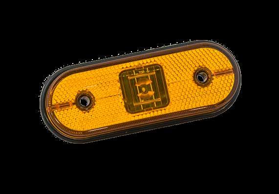
Depending on the colour of the lens, Aspöck position lamps meet different requirements. They stand out above all due to their uniform design and many mounting options.
POSITION LAMPS
FLATPOINT II LED


Impresses with versatile mounting options
PRODUCT FEATURES
STURDY CONSTRUCTION
For a long service life
COMPACT DESIGN
Thanks to flat lens & optionally integrated retro-reflector

HIGHLY DIVERSE VARIANTS
Due to different cable lengths and plug connections
OPTIONALLY AVAILABLE AS DUAL VOLTAGE
For 12 & 24 volt applications


44 24V OEM PRODUCT CATALOGUE [A] [B]
F D B 2 4 6 8 1 3 5 7 2 4 6 8 1 3 5 7 E C A F D B E C A A3 AutoCAD 2019 CP_03-0_Zeichnungsblatt Beschreibung Leidinger Sabine 2022/07/26 U:\Technik-Allgemein\_ProduktZeichnungen_fuer_Marketing\31-2304-017_Flatpoint_II_LED.dwg Marketing Seite 1 (102) (46) (17) bemaßung fehlt noch...
IP 6K9K ADR Zone 2 (82) (82)

45 www.aspoeck.com PART NO. 24V V VERSION FUNCTION CONNECTION CABLE 31-2304-017 1/100 LED 24 V [A] P&R 0.50 m 31-2304-037 1/100 LED 24 V [A] P&R 1.50 m 31-2304-097 1/- LED 12V 24V [A] P&R 1.50 m 31-2307-017 1/50 LED 24 V [A] ASS3 1.50 m 31-2364-017 1/100 LED 24 V [B] P&R 0.50 m 31-2364-037 1/60 LED 24 V [B] P&R 1.50 m 31-2367-057 1/- LED 24 V [B] ASS3 1.50 m 31-2364-087 1/100 LED 24 V [C] P&R 0.50 m 31-2364-107 1/100 LED 24 V [C] P&R 1.50 m 31-2367-037 1/50 LED 24 V [C] ASS3 1.50 m 31-6900-017 1/- LED 24 V [A] Open end 0.50 m 31-6904-017 1/100 LED 24 V [A] P&R 0.50 m 31-6907-027 1/100 LED 24 V [A] ASS3 0.50 m 31-6904-037 1/100 LED 24 V [A] P&R 1.50 m 31-6904-167 1/- LED 12V 24 V [A] P&R 1.50 m 31-6907-037 1/50 LED 24 V [A] ASS3 1.50 m 31-6904-057 1/50 LED 24 V [A] P&R 3.50 m 31-6904-127 1/- LED 24 V [A] P&R 3.50 m 31-6404-017 1/100 LED 24 V [A] P&R 0.50 m 31-6404-097 1/- LED 24 V [A] P&R 0.50 m 31-6404-127 1/- LED 24 V [A] P&R 3.50 m
POSITION LAMPS
UNIPOINT I LED
Extremely sturdy side marker lamps with LED technology


PRODUCT FEATURES
HIGH LIGHT INTENSITY
With low power consumption
SIMPLE MOUNTING
Made easy with many mounting options
VERY STURDY DESIGN
Due to the over-moulded lens and the encapsulated printed circuit board
HIGHLY DIVERSE VARIANTS
Due to different cable lengths and plug connections
46 24V OEM PRODUCT CATALOGUE
IP 6K9K ADR Zone 2


47 www.aspoeck.com [A] [C] [E] [B] [D] PART NO. 24V V VERSION FUNCTIONS ADDITION CONNECTION CABLE 31-2004-017 1/100 LED 24 V [A] P&R 0.50 m 31-2007-237 1/- LED 24 V [A] ASS3 0.50 m 31-2004-037 1/90 LED 24 V [A] P&R 1.50 m 31-2004-107 1/- LED 24 V [A] P&R 1.50 m 31-2007-247 1/50 LED 24 V [A] ASS3 1.50 m 31-2064-017 1/60 LED 24 V [B] P&R 0.50 m 31-2067-097 1/100 LED 24 V [B] ASS3 0.50 m 31-2064-037 1/75 LED 24 V [B] P&R 1.50 m 31-2067-107 1/50 LED 24 V [B] ASS3 1.50 m 31-2064-717 1/90 LED 24 V [C] P&R 0.50 m 31-2064-737 1/75 LED 24 V [C] P&R 1.50 m 31-2064-217 1/90 LED 24 V [D] P&R 0.50 m 31-2064-237 1/60 LED 24 V [D] P&R 1.50 m 31-2064-417 1/50 LED 24 V [E] P&R 0.50 m 31-2064-437 1/50 LED 24 V [E] P&R 1.50 m 2 4 6 8 1 3 5 7 2 4 6 8 1 3 5 7 F D B E C A A3 AutoCAD 2019 CP_03-0_Zeichnungsblatt Beschreibung Leidinger Sabine 2022/07/26 \\at-sys-fscomp\AT\Technik-Allgemein\_ProduktZeichnungen_fuer_Marketing\31-2004-017_Unipoint_I_LED.dwg Marketing Seite 1 (120) (46) (18) (120) (46) (18) Orange winkel fehlen noch
POSITION LAMPS
UNIPOINT MAXX
Extremely sturdy side marker with LED technology

INCREASED SAFETY
Better visibility along the vehicle
HIGH LIGHT INTENSITY
Displaying the maximum allowed light intensity
SIMPLE MOUNTING
Thanks to the specially designed brackets
VERY STURDY DESIGN
Due to the over-moulded lens and the encapsulated printed circuit board
MAXX
48 24V OEM PRODUCT CATALOGUE
IP 6K9K ADR Zone 2
UNIPOINT
PART NO. 24V V FUNCTION ADDITION CONNECTION CABLE 31-2104-067 1/- LED 24 V P&R 2.00 m
PRODUCT FEATURES F D B 2 4 6 8 1 3 5 7 2 4 6 8 1 3 5 7 E C A F D B E C A A3 AutoCAD 2019 CP_03-0_Zeichnungsblatt Beschreibung Leidinger Sabine 2022/07/26 \\at-sys-fscomp\AT\Technik-Allgemein\_ProduktZeichnungen_fuer_Marketing\31-2107-017_Unipoint_MAX.dwg Marketing Seite 1 (120) (45) (19) (70)
UNIPOINT DI
PRODUCT FEATURES
SPACE-SAVING SYSTEM INTEGRATION
Side marker lamp & cat. 5 blinker in one lamp
IMPROVED PERCEPTION
Using far reaching beams
The ECE 48 Rev. 6 regulation states that for vehicles of category O3 and O4, three additional category 5 side marker lamps must be fitted to the trailer as uniformly as possible, and must flash in synchronicity with the truck.

The aim is to significantly increase safety for all road users when turning.
The Unipoint DI directional indicator complies with this legislation. Alternatively, a SMCG can be installed in the vehicle. See description SMCG on page 102.

49 www.aspoeck.com
PART NO. 24V V FUNCTION ADDITION CONNECTION CABLE 31-2107-017 1/50 LED 24 V 3-pin ASS3 1.50 m 31-2104-077 1/- LED 24 V P&R 1.50 m 31-2107-007 1/- LED 24 V ASS3 1.50 m
UNIPOINT I LED


Powerful light output and construction

PRODUCT FEATURES
HIGH LIGHT INTENSITY
With low power consumption
VERY STURDY DESIGN
Due to the over-moulded lens and the encapsulated printed circuit board


HIGHLY DIVERSE VARIANTS
Due to different cable lengths and plug connections
COMPACT DESIGN
With optional retro-reflector integrated in the lamp
50 24V OEM PRODUCT CATALOGUE
IP 6K9K ADR Zone 2
POSITION LAMPS
[A] [C] [B] [D] [B]
51 www.aspoeck.com PART NO. 24V V VERSION FUNCTION ADDITION CONNECTION CABLE 31-7704-017 1/100 LED 24 V [A] P&R 0.50 m 31-7704-097 1/- LED 24 V [B] P&R 0.50 m 31-7707-107 1/50 LED 24 V [A] ASS3 0.50 m 31-7704-077 1/- LED 24 V [A] P&R flat cables 1.00 m 31-7704-037 1/80 LED 24 V [A] P&R 1.50 m 31-7707-117 1/50 LED 24 V [A] ASS3 1.50 m 31-7704-227 1/50 LED 24 V [A] P&R 1.50 m 31-7704-057 1/60 LED 24 V [A] P&R 3.50 m 31-7704-127 1/- LED 24 V [B] P&R 3.50 m 31-7707-127 1/- LED 24 V [B] ASS3 3.50 m 31-7704-087 1/60 LED 24 V [B] P&R flat cables 4.00 m 31-7804-017 1/100 LED 24 V [C] P&R 0.50 m 31-7804-097 1/- LED 24 V [D] P&R 0.50 m 31-7804-077 1/- LED 24 V [C] P&R flat cables 1.00 m 31-7804-057 1/- LED 24 V [C] P&R 3.50 m 31-7804-127 1/10 LED 24 V [D] P&R 3.50 m 31-7804-087 1/- LED 24 V [D] P&R flat cables 4.00 m 2 4 6 8 1 3 5 7 F D B E C A3 AutoCAD 2019 CP_03-0_Zeichnungsblatt Beschreibung Marketing (120) (46) (120) (46) (18) (18) rot und weiß mit Reflektor ohne Reflektor
POSIPOINT II LED


Simple, space-saving installation
PRODUCT FEATURES
HIGH LIGHT OUTPUT
With low power consumption
DIFFERENT MOUNTING OPTIONS
Direct installation on the vehicle or body by means of a bracket (housing)

SLIM DESIGN
Space-saving mounting
DUAL VOLTAGE
For 12 & 24 volt applications
52 24V OEM PRODUCT CATALOGUE
IP 6K9K ADR Zone 2 POSITION LAMPS
Accessory
Positpoint 2.1 LED ?? mit und ohne Schalter oder
53 www.aspoeck.com PART NO. 24V V FUNCTION CONNECTION CABLE 31-7100-067 1/- LED 12V 24V Open end 0.50 m 31-7104-007 1/- LED 12V 24V P&R 0.50 m 31-7104-017 1/130 LED 12V 24V P&R 1.50 m 31-7104-027 1/70 LED 12V 24V P&R 1.50 m 31-7100-017 1/- LED 12V 24V Open end 3.50 m 31-7100-007 1/- LED 12V 24V Open end 5.00 m 31-7200-067 1/50 LED 12V 24V Open end 0.50 m 31-7204-007 1/100 LED 12V 24V P&R 0.50 m 31-7204-017 1/- LED 12V 24V P&R 1.50 m 31-7204-027 1/- LED 12V 24V P&R 1.50 m 31-7200-017 1/70 LED 12V 24V Open end 3.50 m 31-7200-007 1/- LED 12V 24V Open end 3.50 m
PART NO. 15-5609-107 1/- Housing F D B 2 4 6 8 1 3 5 7 2 4 6 8 1 3 5 7 E C A F D B E C A A3 AutoCAD 2019 CP_03-0_Zeichnungsblatt Beschreibung Marketing Seite 2 Leidinger Sabine 2022/07/26 \\at-sys-fscomp\AT\Technik-Allgemein\_ProduktZeichnungen_fuer_Marketing\31-7100-067_Posipoint_II_LED.dwg
ist die Leuchte exclusiv für Schmitz? (82) (25) (19) (58) (82) (25) (19) (58)
MONOPOINT II LED


The quick solution without any screws
PRODUCT FEATURES
SIMPLE MOUNTING
No screws, thanks to special rubber ribs
HIGH LIGHT OUTPUT
With low power consumption
SLIM DESIGN
Space-saving mounting
54 24V OEM PRODUCT CATALOGUE
POSITION LAMPS


55 www.aspoeck.com PART NO. 24V V VERSION FUNCTION CONNECTION CABLE 31-6704-067 1/100 LED 12V 24 V [A] P&R 0.50 m 31-6704-077 1/- LED 12V 24 V [A] P&R 1.50 m 31-6704-087 1/- LED 12V 24 V [A] P&R 3.50 m 31-6700-027 1/20 LED 12V 24 V [A] Open end 3.50 m 31-6704-097 1/- LED 12V 24 V [B] P&R 0.50 m 31-6704-107 1/- LED 12V 24 V [B] P&R 1.50 m 31-6704-117 1/- LED 12V 24 V [B] P&R 3.50 m 31-6700-037 1/20 LED 12V 24 V [B] Open end 3.50 m 31-6804-087 1/- LED 12V 24 V [C] P&R 0.50 m 31-6804-067 1/- LED 12V 24 V [C] P&R 3.50 m 31-6804-097 1/- LED 12V 24 V [C] P&R cable 5.00 m 31-6800-017 1/- LED 12V 24 V [C] Open end 3.50 m 31-6804-077 1/- LED 12V 24 V [D] P&R 3.50 m [A] [B] (29) F D B 2 4 6 8 1 3 5 7 2 4 6 8 1 3 5 7 E C A F D B E C A A3 - AutoCAD 2019 / CP_03-0_Zeichnungsblatt Beschreibung Leidinger Sabine 2022/08/16 \\at-sys-fscomp\AT\Technik-Allgemein\_ProduktZeichnungen_fuer_Marketing\31-6704-067_Monopoint_II_LED.dwg Marketing Seite 1 (12) (Ø38) (Ø21) (54) (37) (Ø38) (Ø21)
END-OUTLINE MARKER LAMPS
FLEXPOINT I LED
SUPERPOINT IV LED
SUPERPOINT III LED
SUPERPOINT II
NUMBER PLATE LAMPS
BEACONS INTERIOR LAMPS
WORK LAMPS
NUMBER PLATE HOLDERS
SIDE MARKER LAMPS
REVERSING LAMPS
BRAKE LIGHT
POSITIONS LAMPS
END-OUTLINE MARKER LAMPS
REAR LAMPS
NUMBER PLATE LAMPS
BEACONS
INTERIOR LAMPS
LAMPS
NUMBER PLATE HOLDERS
Multiple mounting options are one of the many product features that the end-outline marker lamps from Aspöck Systems have to offer. These lamps also increase the safety of your vehicle due to their high visibility.

SUPERPOINT IV LED

Universal application across different versions
PRODUCT FEATURES
RESISTANT DESIGN
Flexible mounting arm in different versions
HIGH LIGHT OUTPUT
With low power consumption
LED END-OUTLINE MARKER LAMP
With a clear design
HIGHLY DIVERSE VARIANTS
Due to different brackets, cable lengths and plug connections
INCLUDING SIDE MARKER LAMP
Either in orange or red
DUAL VOLTAGE
For 12 & 24 volt applications
58 24V OEM PRODUCT CATALOGUE
IP 69K ADR Zone 2 END-OUTLINE MARKER LAMPS


59 www.aspoeck.com PART NO. PART NO. 24V V VERSION ADDITION CONNECTION CABLE 31-3104-007 31-3104-017 1/50 LED 12V 24 V [A] P&R 2.00 m 31-3105-017 31-3106-017 1/50 LED 12V 24 V [A] ASS2 0.50 m 31-3105-007 31-3106-007 1/50 LED 12V 24 V [A] ASS2 2.00 m 31-3104-087 31-3104-097 1/- LED 12V 24 V [B] P&R 2.00 m 31-3104-047 31-3104-057 1/- LED 12V 24 V [C] P&R 2.00 m 31-3104-067 31-3104-077 1/- LED 12V 24 V [D] P&R 2.00 m [A] [B] [C] [D] (176) (10) (105) (65.5) (6) (98) (54) (12) (130.5) (9.5) (54) (78) (61.5) (98.5) (54) (77)
SUPERPOINT III LED

Powerful form and light performance
PRODUCT FEATURES
MANY MOUNTING OPTIONS
Due to a large selection of brackets
HIGH LIGHT OUTPUT
With low power consumption
SAME ITEM CAN BE USED ON BOTH SIDES
For bracket version [B] and [D]
DURABLE DESIGN
Break-proof, weather-resistant and flexible material
60 24V OEM PRODUCT CATALOGUE
IP 69K ADR Zone 2 END-OUTLINE MARKER LAMPS


61 www.aspoeck.com PART NO. PART NO. 24V V VERSION ADDITION CONNECTION CABLE 31-3304-047 31-3304-057 1/50 LED 24 V [A] P&R 1.25 m 31-3304-067 31-3304-077 1/- LED 24 V [A] P&R 1.25 m 31-3305-127 31-3306-127 1/- LED 24 V [A] ASS3 1.25 m 31-3305-017 31-3306-017 1/- LED 24 V [A] ASS2 1.75 m 31-3303-007 31-3302-007 1/25 LED 24 V [A] Open end 4.00 m 31-3303-017 31-3302-017 1/- LED 24 V [A] Open end 4.00 m 31-3364-007 1/50 LED 24 V [B] P&R 1.50 m 31-3360-007 1/25 LED 24 V [B] Open end 4.00 m 31-3364-017 1/- LED 24 V [B] P&R 1.50 m 31-3360-017 1/- LED 24 V [B] Open end 4.00 m 31-3364-057 31-3364-027 1/50 LED 24 V [C] P&R 1.50 m 31-3365-017 31-3366-027 1/- LED 24 V [C] Open end 4.00 m 31-3364-047 31-3364-037 1/- LED 24 V [C] P&R 1.50 m 31-3365-027 31-3366-017 1/- LED 24 V [C] Open end 4.00 m 31-3304-087 1/- LED 24 V [D] P&R 1.25 m 31-3307-017 1/50 LED 24 V [D] ASS2 1.75 m 31-3307-007 1/- LED 24 V [D] ASS2 1.75 m 31-3300-247 1/40 LED 24 V [D] Open end 4.00 m [A] [B] [C] [D] (173) (78.5) (104) (64) (93.2) (104.8) (125) (78.5) (104) (64) (77) (98.6)
NUMBER PLATE LAMPS
FLEXLED
REGPOINT II LED
REGPOINT I LED
REGPOINT I
NUMBER PLATE LAMPS
BEACONS INTERIOR LAMPS
WORK LAMPS
NUMBER PLATE HOLDERS
SIDE MARKER LAMPS
REVERSING LAMPS
BRAKE LIGHT
POSITIONS LAMPS
END-OUTLINE MARKER LAMPS
REAR LAMPS
NUMBER PLATE LAMPS
BEACONS
INTERIOR LAMPS
LAMPS
NUMBER PLATE HOLDERS
For the best possible illumination of a number plate, Aspöck offers a range of number plate lights with different designs and various connections.

NUMBER
REGPOINT II LED


Two designs for maximum flexibility
PRODUCT FEATURES
SIMPLE MOUNTING
Thanks to installed bolts
HIGHLY DIVERSE VARIANTS
Due to different cable lengths and plug connections
HIGH LIGHT OUTPUT
With low power consumption
SINGLE MOUNTING POSSIBLE
Through use of the raised version with base
DUAL VOLTAGE
For 12 & 24 volt applications
64 24V OEM PRODUCT CATALOGUE
PLATE LAMPS
IP 6K9K ADR Zone 2


65 www.aspoeck.com PART NO. 24V V VERSION MOUNTING CONNECTION CABLE 36-3804-007 1/100 LED 12V 24V [A] P&R 0.50 m 36-3804-017 1/50 LED 12V 24V [A] P&R 2.00 m 36-3806-007 1/50 LED 12V 24V [A] ASS2 0.50 m 36-3805-007 1/25 LED 12V 24V [A] ASS2 2.00 m 36-3810-007 1/50 LED 12V 24V [A] ASS3 0.50 m 36-3864-007 1/- LED 12V 24V [B] P&R 0.50 m 36-3864-017 1/50 LED 12V 24V [B] P&R 2.00 m 36-3867-017 1/- LED 12V 24V [B] ASS2 0.50 m 36-3867-027 1/50 LED 12V 24V [B] ASS2 2.00 m 36-3865-007 1/- LED 12V 24V [B] ASS3 0.50 m [A] [B]
F D B 2 4 6 8 1 3 5 7 2 4 6 8 1 3 5 7 E C A F D B E C A A3 - AutoCAD 2019 / CP_03-0_Zeichnungsblatt Beschreibung Leidinger Sabine 2022/07/26 \\at-sys-fscomp\AT\Technik-Allgemein\_ProduktZeichnungen_fuer_Marketing\36-3804-007_Regpoint_II_LED.dwg Marketing Seite 1 (72) (98) (48) (50) (72) (100) (83) (45) (45) (55)
SINGLE MOUNTING Version DOUBLE MOUNTING Version
REGPOINT I & REGPOINT I LED
A wide range with practical application
PRODUCT FEATURES
SIMPLE MOUNTING
Thanks to installed bolts
HIGHLY DIVERSE VARIANTS
Due to different cable lengths and plug connections
HIGH LIGHT OUTPUT FOR LED

With low power consumption

66 24V OEM PRODUCT CATALOGUE
ADR Zone 2 IP 54 NUMBER PLATE LAMPS


67 www.aspoeck.com PART NO. 24V V MOUNTING CONNECTION CABLE 36-3604-007 1/- LED 24 V P&R 0.50 m 36-3604-017 1/80 LED 24 V P&R 1.00 m 36-3604-027 1/40 LED 24 V P&R 3.50 m 36-3607-007 1/- LED 24 V ASS2 0.50 m 36-3607-017 1/50 LED 24 V ASS2 1.00 m 36-3607-027 1/40 LED 24 V ASS2 3.50 m 36-3004-017 1/100 24 V P&R 0.50 m 36-3004-027 1/100 24 V P&R 1.00 m 36-3004-057 1/- 24 V P&R 3.50 m 36-3007-007 1/90 24 V ASS2 0.50 m 36-3007-057 1/50 24 V ASS2 1.00 m 36-3007-047 1/20 24 V ASS2 2.50 m 36-3007-397 1/90 24 V ASS3 0.50 m
F D B 2 4 6 8 1 3 5 7 2 4 6 8 1 3 5 7 E C A F D B E C A A3 - AutoCAD 2019 / CP_03-0_Zeichnungsblatt Beschreibung Leidinger Sabine 2022/08/16 \\at-sys-fscomp\AT\Technik-Allgemein\_ProduktZeichnungen_fuer_Marketing\36-3604-007_Regpoint_I_LED.dwg Marketing Seite 1 (72) (100) (59) (58)
LEDVersion LIGHT BULB Version
FLEXLED NUMBER PLATE HOLDER


Innovative quick mounting and locking system
PRODUCT FEATURES
LOCKING SYSTEM WITH QUICK CLAMPING
Quick and easy number plate change
SMART QUICK-MOUNTING SYSTEM
Simple mounting of the holder on the vehicle
FOR ALL EU NUMBER PLATES
Suitable for 110 and 120 mm height

ADR-APPROVED
Tested for zone 2
HOMOGENEOUS ILLUMINATION
Thanks to integrated FlexLED strip
68 24V OEM PRODUCT CATALOGUE
IP 6K9K ADR Zone 2 NUMBER PLATE LAMPS


69 www.aspoeck.com PART NO. 24V V CONNECTION CABLE 36-3704-107 1/- LED 24 V Open end 0.50 m 36-3704-197 1/- LED 24 V Open end 1.50 m 36-3704-147 1/- LED 24 V P&R 0.50 m 36-3704-117 1/- LED 24 V P&R 1.50 m 36-3704-137 1/- LED 24 V ASS2 0.50 m 36-3704-177 1/- LED 24 V ASS2 1.50 m 36-3704-157 1/- LED 24 V Superseal 0.50 m 36-3704-187 1/- LED 24 V Superseal 1.50 m F D B 2 4 6 8 1 3 5 7 2 4 6 8 1 3 5 7 E C A F D B E C A A3 - AutoCAD 2019 / CP_03-0_Zeichnungsblatt Beschreibung Leidinger Sabine 2022/07/26 W:\Acad_Config\Library\Parts\B_Leuchten\B_Monopoint\36-3704-107_Kennzeichenhalter FlexLED.dwg Marketing Seite 1 (540) (145) (37) PART NO. DESCRIPTION 15-5300-427 1/100 Mounting clip
Mounting clip
ACCESSORY
WORK & REVERSING LAMPS
NUMBER PLATE LAMPS BEACONS INTERIOR LAMPS
WORK LAMPS
NUMBER PLATE HOLDERS
SIDE MARKER LAMPS
BRAKE LIGHT REVERSING LAMPS
POSITIONS LAMPS
END-OUTLINE MARKER LAMPS
REAR LAMPS
NUMBER PLATE LAMPS
BEACONS
INTERIOR LAMPS
LAMPS
NUMBER PLATE HOLDERS
II 3000 WORKPOINT II 1500 WORKPOINT II 1000
WORKPOINT
Working in the dark or in poor lighting conditions often demands a lot from you. These specially developed work lamps provide a reliable light source and ensure optimum light distribution during the day and at night.

WORKPOINT II 3000
LED work lamp & reversing light with large adjustment angle
PRODUCT FEATURES
HIGH EFFICIENCY Due to >95 lumens/watt

LARGE VERTICAL SWIVEL RANGE
From -67° to +127°
LIGHT AND COMPACT
A weight of only 660 grams
LIGHT COLOUR SIMILAR TO DAYLIGHT
5700 Kelvin
HOMOLOGATED REVERSING LIGHT
According to ECE R23
EXCELLENT CORROSION RESISTANCE
Powder-coated aluminium heat sink
OPTIMAL LIGHT DISTRIBUTION
With innovative optics
HIGH-QUALITY MATERIALS


Bracket and screws are made of stainless steel
DUAL VOLTAGE
For 12 & 24 volt applications
72 24V OEM PRODUCT CATALOGUE
WORK & REVERSING LAMPS
IP 6K9K ADR Zone 2 E E R10
ACCESSORY


73 www.aspoeck.com PART NO. 24V V DESCRIPTION LUMEN CONNECTION CABLE 28-8524-037 1/16 LED 12V 24 V 20° beam angle 3000 DT on housing28-8524-047 1/16 LED 12V 24 V 60° beam angle 3000 DT on housing38-8524-037 1/16 LED 12V 24 V 20° beam angle 3000 Open end 1.50 m 38-8524-047 1/16 LED 12V 24 V 60° beam angle 3000 Open end 1.50 m
PART NO. DESCRIPTION CONNECTION 14-4302-227 1/- Omega bracket 69-0236-017 1/- Extension for DT version 3.00 m open end 69-0236-007 1/- Extension for DT version 5.00 m open end 77.8 54.6 Side Scale: 77.8 27.4 36.1 54.6 Side view Scale: 1:1 Can be swivelled up to -67° Can be swivelled up to +127° (121) (84) (28) (36) (55) (78)
WORKPOINT II 1500
Compact LED work & reversing light with high efficiency

PRODUCT FEATURES
HIGH EFFICIENCY
Due to >125 lumens/watt
LARGE VERTICAL SWIVEL RANGE
From -35° to +100°
LIGHT AND COMPACT
A weight of only 560 grams
LIGHT COLOUR SIMILAR TO DAYLIGHT
5700 Kelvin
HOMOLOGATED REVERSING LIGHT
According to ECE R23
EXCELLENT CORROSION RESISTANCE
Powder-coated aluminium heat sink
OPTIMAL LIGHT DISTRIBUTION
With innovative optics
HIGH-QUALITY MATERIALS
Bracket and screws are made of stainless steel
DUAL VOLTAGE
For 12 & 24 volt applications

74 24V OEM PRODUCT CATALOGUE
WORK & REVERSING LAMPS
IP 6K9K ADR Zone 2 E E R10
ACCESSORY


75 www.aspoeck.com PART NO. 24V V DESCRIPTION LUMEN CONNECTION CABLE 28-8524-007 1/24 LED 12V 24 V 60° beam angle 1500 DT on housing38-8524-007 1/24 LED 12V 24 V 60° beam angle 1500 Open end 1.50 m 38-8524-057 1/24 LED 12V 24 V 60° beam angle 1500 ASS2 1.50 m Position -35° Position 0° Position +100° 93 121 122 13 36 45 84 70 43.5 45 28 PART NO. DESCRIPTION CONNECTION 14-4302-227 1/- Omega bracket 69-0236-017 1/- Extension for DT version 3.00 m open end 69-0236-007 1/- Extension for DT version 5.00 m open end
Omega bracket as optional accessory
WORKPOINT II 1000
Compact design, flexible use
PRODUCT FEATURES
HIGH EFFICIENCY Due to >100 lumens/watt

LARGE VERTICAL SWIVEL RANGE
From -40° to +110°
LIGHT COLOUR SIMILAR TO DAYLIGHT
5700 Kelvin
LIGHT AND COMPACT
A weight of only 412 grams
HOMOLOGATED REVERSING LIGHT
According to ECE R23
CORROSION RESISTANT & HEAT DISSIPATING Due to thermally conductive plastic

OPTIMAL LIGHT DISTRIBUTION
With innovative optics
HIGH-QUALITY MATERIALS
Bracket and screws are made of stainless steel
DUAL VOLTAGE
For 12 & 24 volt applications
76 24V OEM PRODUCT CATALOGUE
IP 6K9K ADR Zone 2
WORK & REVERSING LAMPS E E R10
ACCESSORY


77 www.aspoeck.com PART NO. 24V V DESCRIPTION LUMEN CONNECTION CABLE 28-8524-017 1/24 LED 12V 24 V 60° beam angle 1000 DT on housing38-8524-017 1/24 LED 12V 24 V 60° beam angle 1000 Open end 1.50 m 38-8524-067 1/24 LED 12V 24 V 60° beam angle 1000 ASS2 1.50 m PART NO. DESCRIPTION CONNECTION 14-4302-227 1/- Omega bracket 69-0236-017 1/- Extension for DT version 3.00 m open end 69-0236-007 1/- Extension for DT version 5.00 m open end Position -40° Position 0° Position +110° (93) (85) (110) (12) (M10) 20 (36) (45) (72) (67) (43.5) (45) (28)
Omega bracket as optional accessory
FLEXLED STRIPS & INTERIOR LAMPS
FLEXLED
INPOINT III LED
NUMBER PLATE LAMPS BEACONS INTERIOR LAMPS
WORK LAMPS
NUMBER PLATE HOLDERS
SIDE MARKER LAMPS
REVERSING LAMPS
BRAKE LIGHT
POSITIONS LAMPS
END-OUTLINE MARKER LAMPS
REAR LAMPS
NUMBER PLATE LAMPS
BEACONS
INTERIOR LAMPS
LAMPS
NUMBER PLATE HOLDERS
Nowadays, it is not only the vehicle lighting on the outside that plays a crucial role. Interior lighting is also becoming increasingly important. Aspöck Systems offers an individual combination of design and functionality.

ASPÖCK FLEXLED LED STRIPS

FlexLED – light strips with a design factor
Future-proof LED technology merged with sleek design - when it comes to innovative vehicle lighting, appearance plays an important role alongside safety. Aspöck FlexLED has picked up on this trend and combined it with a system solution. Whether in the passenger compartment or in the loading area, Aspöck Systems offers you the perfect solution for your vehicle.


The LED strips are divided into the following categories and are available in the respective sizes depending on the category:


CHARACTERISTICS

80 24V OEM PRODUCT CATALOGUE
IP 6K9K Protection classification CISPR class3 ECE R10 Electromagnetic compatibility Can be homologated ADR ADR-capable Resistant to chemicals 10-2000Hz vibration 51g shock Shock and vibration-resistant Rear light, 3rd brake light, position lamp Status display and special lighting Work
ambient lighting
and
FlexLED small FlexLED medium FlexLED large
FlexLED Kelvin FlexLED ECE FlexLED Monochrome
FLEXLED KELVIN
LED strips, ideal for work and ambient lighting
PRODUCT FEATURES
USE: WORK & AMBIENT LIGHTING

Optimised light distribution ensures reduced shadows in working areas
GLARE-FREE LIGHT SOURCE
Due to the linear light emission
INTEGRATION IN VEHICLE STRUCTURAL COMPONENTS
Perfect illumination for the interior and exterior of the vehicle

LIGHT COLOUR: WARM WHITE TO COLD WHITE
2700 Kelvin to 6000 kelvin
DIFFERENT LIGHT OUTPUTS
From 270 lumens/m to 1500 lumens/m
STURDY DESIGN
Vibration, shock and chemical resistant
CASTING TRANSPARENT OR DIFFUSE
Depending on the area of application and requirement
81 www.aspoeck.com
ADR Zone 2
ECE LIGHT FUNCTIONS
Approved in line with ECE REG 48
PRODUCT FEATURES
AVAILABLE IN LARGE PROFILE
For homogeneous light emission and elegant cold design
STURDY DESIGN
Vibration, shock and chemical resistant

CUSTOMISED SOLUTIONS

Customised lengths for every lighting function

AVAILABLE IN ALL ECE COLOURS
Red, yellow, white
82 24V OEM PRODUCT CATALOGUE
Position lamp for truck trailers
3rd stop lamp and position lamps for truck trailers
Side marker lamp for truck trailers
ADR Zone 2
FLEXLED MONOCHROME
LED strips, ideal for status and special lighting
ADR
Zone
HIGH LIGHT PERFORMANCE
Using single-colour LEDs

POWERFUL STATUS DISPLAYS
AVAILABLE IN SMALL, MEDIUM AND LARGE
Enables universal use
83 www.aspoeck.com
Thanks to freely selectable colour combinations 2
PRODUCT FEATURES
PRODUCT VERSIONS
The LED strips are available in the following sizes, depending on the product category


FLEXLED SMALL
For a length up to 15 m
Compact & space-saving
Small bend radius of 10 cm
FLEXLED MEDIUM
Can be used with profiles
The multi purpose LED strip
Small bend radius of 15 cm
For a lenght up to 5 m
FLEXLED LARGE
Designed for homologisable lighting functions
Diffuse casting for homogeneous light emission
Sturdy design
For a lenght up to 5 m
Small bend radius of 20 cm
84 24V OEM PRODUCT CATALOGUE
15.8 mm 8 mm
5.5 mm 12.6 mm 15 mm 15.8 mm
FLEXLED PROFILE
Easy attachment due to medium mounting profiles


85 www.aspoeck.com Flat profile 45° corner profile End cover Ramp profile PART NO. DESCRIPTION COLOUR LENGTH 14-4230-677 Mounting bracket corner profile medium Grey RAL 7035 1.00 m 14-4130-647 Mounting bracket corner profile medium Black RAL 9005 1.00 m 14-4230-657 Mounting bracket ramp profile medium Grey RAL 7035 1.00 m 14-4230-627 Mounting bracket ramp profile medium Black RAL 9005 1.00 m 14-4230-667 Mounting bracket flat profile medium Grey RAL 7035 1.00 m 14-4230-637 Mounting bracket flat profile medium Black RAL 9005 1.00 m 15-5250-737 LED strip cover Transparent 1.00 m 15-5250-747 LED strip cover Diffuse 1.00 m 15-5250-757 LED strip blind zone end cover Grey RAL 7035 1.00 m 15-5250-767 LED strip blind zone end cover Black RAL 9005 1.00 m
Interior lighting for truck trailers / mounting with corner profile
INPOINT III LED


The optimum interior light for multiple applications

PRODUCT FEATURES
LONG LIFE SPAN
Thanks to sturdy construction
OPTIMAL WORK LIGHT
Light colour 6000 kelvin
HIGH LIGHT OUTPUT
With low power consumption
THREE VERSIONS
Optionally with switch or motion sensor
DUAL VOLTAGE
For 12 & 24 volt applications
MODERN LOOK
Lens in frosted optics
86 24V OEM PRODUCT CATALOGUE
ADR Zone 2


87 www.aspoeck.com [A] [B] [C] PART NO. 24V V VERSION ADDITION LUMEN CONNECTION CABLE 39-8900-157 1/- LED 12V 24V [A] IP 6K9K 700 lumens Open end 0.30 m 39-8900-207 1/- LED 12V 24V [A] with motion sensor IP 67 700 lumens Open end 0.30 m 39-8900-257 1/- LED 12V 24V [A] with switch IP 6K9K 700 lumens Open end 0.30 m 39-8900-007 1/- LED 12V 24V [B] IP 6K9K 1,400 lumens Open end 0.30 m 39-8900-057 1/- LED 12V 24V [B] with motion sensor IP 67 1,400 lumens Open end 0.30 m 39-8900-107 1/- LED 12V 24V [B] with switch IP 6K9K 1,400 lumens Open end 0.30 m 39-8900-307 1/- LED 12V 24V [C] IP 6K9K 2,200 lumens Open end 0.30 m 39-8900-357 1/- LED 12V 24V [C] with motion sensor IP 67 2,200 lumens Open end 0.30 m 39-8900-401 1/- LED 12V 24V [C] with switch IP 6K9K 2,200 lumens Open end 0.30 m (35) (2 x 0.5 mm³) (2 x 0.5 mm³) (112,5±0.3) (57.5±0.3) (15±0.1) Screws included ST4.2*20 Screws included ST4.2*20 (35) (300) (172,5±0.3) (57,5±0.1) (159,6 ±0.5) (15±0.1) Screws included T4.2*20 Screws included ST4.2*20 (Ø130) (35) (300) (Ø102) (2 x 0.5 mm³) (17) (300)
WIRING & JUNCTION BOXES
SML FEED LINE
DISTRIBUTOR XL
ASS DISTRIBUTOR
MAIN CABLES
P&R FLAT CABLES
FEED LINES
SOCKET DISTRIBUTORS
NUMBER PLATE LAMPS BEACONS
INTERIOR LAMPS
WORK LAMPS
NUMBER PLATE HOLDERS
SIDE MARKER LAMPS
REVERSING LAMPS
BRAKE LIGHT
POSITIONS LAMPS
END-OUTLINE MARKER LAMPS
REAR LAMPS
NUMBER PLATE LAMPS
BEACONS
INTERIOR LAMPS
LAMPS
NUMBER PLATE HOLDERS
In addition to vehicle lighting of all kinds, cable and plug-in systems round off the wide range of Aspöck products. Always with the highest level of quality, we give our all to fulfil every customer-specific requirement in the best possible way.


ASPÖCK WIRING & LIGHT SYSTEMS
The heart of every vehicle – the wiring. It provides the connection that makes the lamps shine in the first place.

That is why Aspöck Systems offers a wide range of standard wiring systems for all of the segments that are available to our customers directly from the warehouse, from ADR cables to cables for electronic applications (BUS).
But what would a cable be without a proper connection? There is a wide variety of connector systems available for connecting the cables to various system components. An outstanding example is the ASPÖCK connector system (ASS) developed in-house.
Aspöck is a pioneer, especially in the areas of wiring and junction boxes. We respond to individual customer requests and adapt wiring systems precisely to their requirements with regards to cable length, plug connections, etc.
90 24V OEM PRODUCT CATALOGUE
FEED LINE

Socket distributor
Feed lines
MAIN WIRING
WIRING FOR SIDE MARKER LAMPS
JUNCTION BOX & WIRING
ASS2 distributor
XL distributor
Rear supply harness
91 www.aspoeck.com F D B 2 4 6 8 1 3 5 7 2 4 6 8 1 3 5 7 E C A F D B E C A A3 AutoCAD 2019 CP_03-0_Zeichnungsblatt Beschreibung Hager Cornelia 2022/07/26 U:\Technik-Allgemein\_ProduktZeichnungen_fuer_Marketing\KIT_Standartverkabelung.dwg Marketing Seite 1 socket insert 7p.black DIN/ISO 1185 7p.schwarz socket insert 7p.white DIN/ISO 3731 7p.weiss socket insert 15p. DIN/ISO 12098 15p. LABEL
3-SOCKET JUNCTION BOX

This makes the 3-compartment socket distributor permissible for ADR Zone 2 : To make the socket distributor compatible with ADR travel, you must use the ADR safety caps for the ISO 1185 and ISO 3731 sockets.


92 24V OEM PRODUCT CATALOGUE WIRING & JUNCTION BOXES FEED LINE
PART NO. CABLE 76-7037-007 1/- Socket 15-pin ISO 12098 + socket ISO 1185 & 3731 (N+S) ASS3 15-pin female connector 0.60 m 76-7069-007 1/- Socket 15-pin ISO 12098 + socket ISO 1185 & 3731 (N+S) ASS3 15-pin female connector Direct connection (247) (224) (175) (120) PART NO. DESCRIPTION 15-5280-154 1/- 2-piece safety caps for sockets ISO 1185 and ISO 3731 PART NO. CABLE 76-7072-007 1/- Socket 15-pin ISO 12098 ASS3 15-pin female connector 0.60 m 600 12 x 1+3 x 2.5 (175) (247) (224) ADR Zone 2
FEED LINES


93 www.aspoeck.com
PART NO. DESCRIPTION CABLE 53-1667-037 1/- Plug 15-pin ISO 12098 4.80 m ISO 12098 ASS3 female connector (4.8 m) PART NO. DESCRIPTION CABLE 58-6024-017 1/- Plug ISO 1185 & 3731 (N+S) 4.80 m ISO 1185 ISO 3731 ASS3 female connector (4.8 m) PART NO. DESCRIPTION CABLE 53-6768-007 1/- Socket 15-pin ISO 12098 0.60 m ASS3 female connector ISO 12098 (0.6 m) PART NO. DESCRIPTION CABLE 58-6649-007 1/- Socket ISO 1185 & 3731 (N+S) 0.60 m ASS3 female connector ISO 3731 ISO 1185 PART NO. DESCRIPTION CABLE 58-6647-007 1/- Socket 15-pin ISO 12098 + socket ISO 1185 & 3731 (N+S) 0.60 m (0.6 m) (0.6 m) ASS3 female connector ISO 1185 ISO 12098 ISO 3731 (0.6 m) (0.6 m) (4.8 m)
MAIN CABLES

94 24V OEM PRODUCT CATALOGUE
PART NO. DESCRIPTION CABLE 65-1003-007 1/- 2 x ASS3 15-pin male connector 6 x 1.00 mm² + 2 x 2.50 mm 9.00 m 65-1003-017 1/- 2 x ASS3 15-pin male connector 6 x 1.00 mm² + 2 x 2.50 mm² 12.50 m 65-1003-027 1/- 2 x ASS3 15-pin male connector 6 x 1.00 mm² + 2 x 2.50 mm² 15.00 m 65-1005-007 1/- 2 x ASS3 15-pin male connector 7 x 1.00 mm² + 1 x 1.50 mm² + 2 x 2.50 mm² 9.00 m 65-1005-017 1/- 2 x ASS3 15-pin male connector 7 x 1.00 mm² + 1 x 1.50 mm² + 2 x 2.50 mm² 12.50 m 65-1005-027 1/- 2 x ASS3 15-pin male connector 7 x 1.00 mm² + 1 x 1.50 mm² + 2 x 2.50 mm² 15.00 m 65-1007-007 1/- 2 x ASS3 15-pin male connector 12 x 1.00 mm² + 3 x 2.50 mm² 9.00 m 65-1007-017 1/- 2 x ASS3 15-pin male connector 12 x 1.00 mm² + 3 x 2.50 mm² 12.50 m 65-1007-027 1/- 2 x ASS3 15-pin male connector 12 x 1.00 mm² + 3 x 2.50 mm²² 15.00 m ASS3 male connector ASS3 male connector
WIRING & JUNCTION BOXES MAIN CABLES / SML WIRING
SML WIRING


95 www.aspoeck.com PART NO. DESCRIPTION CABLE 87-1284-007 1/- ASS2 2-pin female connector (BL) + 5 x ASS3 2-pin 2 x 1.00 mm² (ADR) 1 x 5.50 m + 4 x 3.70 m PART NO. DESCRIPTION CABLE 87-1285-007 1/- ASS2 2-pin female connector (BL) + 6 x ASS3 2-pin 2 x 1.00 mm² (ADR) 1 x 3.50 m + 5 x 3.70 m
PART NO. DESCRIPTION CABLE 68-7503-047 1/- ASS2 2-pin female connector (YL/GN) P&R flat cable 2 x 1.50 mm² (ADR) WH 10.00 m 68-7503-007 1/- ASS2 2-pin female connector (YL/GN) P&R flat cable 2 x 1.50 mm² (ADR) WH 13.00 m 68-7502-367 1/- ASS2 2-pin female connector (YL/GN) P&R flat cable 2 x 1.50 mm² (ADR) YL/GN 13.00 m 68-7503-017 1/- ASS2 2-pin female connector (YL/GN) P&R flat cable 2 x 1.50 mm² (ADR) WH 15.00 m 68-7503-177 1/- ASS2 2-pin female connector (YL/GN) P&R flat cable 2 x 1.50 mm² (ADR) WH 16.00 m 68-7503-027 1/- ASS2 2-pin female connector (YL/GN) P&R flat cable 2 x 1.50 mm² (ADR) WH 17.00 m 68-7502-377 1/- ASS2 2-pin female connector (YL/GN) P&R flat cable 2 x 1.50 mm² (ADR) YL/GN 17.00 m 3700 3700 3700 3700 5500 mm 3-pin ASS3 male connector 2 x 1.5 mm 2 x 1.5 mm 3700 3700 3700 3700 3700 3500 mm 3-pin ASS3 male connector
JUNCTION BOX XL
With improved sealing and an innovative diaphragm ventilation system
PRODUCT FEATURES
IMPROVED OVERVIEW
Larger design compared to ASS1
INNOVATIVE DIAPHRAGM VENTILATION SYSTEM
Prevents negative pressure or overpressure in the junction box
HIGHER LEAK TIGHTNESS CLASS IP56K
Due to the improved sealing system between cover and housing
OPTIONAL SPECIAL FUNCTIONS
E.g. relays, SMCG, fuses & diodes, due to integrated relay bases and brackets
BETTER MAINTENANCE AT CUSTOMER SITE
Option for more organised cable routing

96 24V OEM PRODUCT CATALOGUE WIRING & JUNCTION BOXES JUNCTION BOX + WIRING
IP 56K
ADR Zone 2


97 www.aspoeck.com PART NO. DESCRIPTION 76-5203-007 1/- Distributor box XL Standard + ASS3 (232) (130) (242) (104) (218)
ASS1 JUNCTION BOX
PRODUCT FEATURES
TIME-SAVING AND LIGHTER INSTALLATION
Pre-wiring possible
SAFE & SIMPLE HANDLING
No need to open the junction box – IP54 tightness guaranteed


FUNCTIONS EXPANDABLE
Free inputs on the housing cover serve as reserve inputs
98 24V OEM PRODUCT CATALOGUE
IP 54
WIRING & JUNCTION BOXES JUNCTION BOX + WIRING
festziehen TOP ASPÖCK SYSTEM Klemmbereiche f. Kabeldurchmesser: Dichtstopfen schwarz 5 6m Dichtstopfen blau 9 10m Dichtstopfen weiß 7 8m Dichtstopfen braun 2x5 - 6m Dichtstopfen rot 11 13mm DICHTMUTTERN bis zum Anschlag (116) (180) festziehen TOP SYSTEM ASPÖCK Dichtstopfen braun 2x5 6mm Dichtstopfen weiß 7 - 8m Dichtstopfen blau 9 10m Dichtstopfen rot 11 13mm DICHTMUTTERN bis zum Anschlag Klemmbereiche f. Kabeldurchmesser: Dichtstopfen schwarz 5 - 6m (116) (1500) (1300) (1300) (180) festziehen g Dichtstopfen rot 11 13mm Dichtstopfen blau 9 10mm Dichtstopfen weiß 7 - 8m Dichtstopfen braun 2x5 6m Dichtstopfen schwarz 5 - 6m Klemmbereiche f. Kabeldurchmesser: SYSTEM ASPÖCK TOP RFS ge (1 NS (3 or (15) vi (14) rs (12) rt 54 (7 ws 31 (4 br/rt(10) ge/sw 1) br/bl gn R (2 br 58R (6 ws/sw "S" (13) sw 58 (5 (80) ASPÖCK gr RFS ge L (1 bl NS (3 (15) (14) (12) 54 (7 ws 31 br/rt(10) ge/sw (1 1) br/bl (9 gn R (2 br 58R (6 ws/sw "S" (13) sw 58 Anschlag Dichtstopfen rot 11 - 13m Dichtstopfen blau 9 - 10m SYSTEM ASPÖCK Dichtstopfen braun 2x5 6m Dichtstopfen schwarz 5 - 6m Klemmbereiche f. Kabeldurchmesser: TOP Dichtstopfen weiß 7 8m (116) (180) (57.5) (72) (50.5) PART NO. DESCRIPTION OUTLETS 76-5123-007 1/- Connections: 1 x ASS3 15-pin female connector; 1 x ASS3 15-pin male connector Not assigned 76-6430-007 1/Connections: 1 x ASS3 15-pin female connector on 1.50 m 15-pin cable; 2 x ASS2 7-pin female connector (YL/GN) on 1.30 m 7-pin cable Rear light left + rear light right 76-5123-117 1/- Connections: 1 x ASS3 15-pin female connector SMCG left & right 76-6430-267 1/- Connections: 1 x ASS3 15-pin female connector on 1.50 m 15-pin cable SMCG left & right + Rear light left + rear light right
REAR SUPPLY HARNESS

99 www.aspoeck.com
PART NO. DESCRIPTION CABLE 68-4800-007 1/- No 2-pin outlet 2 x 2.50 m 2 x 7 x 1 mm² 68-4983-007 1/- Outlets: 2 x ASS2 2-pin male connector (YL/GN) 2 x 2.50 m + 2 x 1.70 m 2 x 7 x 1 mm² + 2 x 2 x 1.50 mm² (P&R) 68-4855-007 1/- Outlets: 1 x P&R flat cable 2 x 3.00 m + 1 x 1.00 m 2 x 7 x 1 mm² + 1 x 2 x 1.50 mm² (P&R) 68-4888-007 1/- Outlets: 2 x SMCG + ASS2 2-pin male connector (YL/GN) 2 x 2.50 m + 2 x 0.70 m 2 x 7 x 1 mm² + 2 x 0.75 mm² (1.65m) (1.65m) (2.5m) (2.5m) 2-pin ASS2 7-pin ASS2 7-pin ASS2 2-pin ASS2 ASS3 Female connector
Connector ASS3 15-pin female connector / 2x ASS2 7-pin female connector
ACCESSORIES
SMCG
ERD
REVERSING WARNING DEVICE
LCG - LED CONTROL GEAR
RDC PREMIUM
SMARTLINK
CONTOUR MARKINGS
EXPANSIONS
NUMBER PLATE LAMPS
BEACONS INTERIOR LAMPS
WORK LAMPS
NUMBER PLATE HOLDERS
SIDE MARKER LAMPS
REVERSING LAMPS
BRAKE LIGHT
POSITIONS LAMPS
END-OUTLINE MARKER LAMPS
REAR LAMPS
NUMBER PLATE LAMPS
BEACONS
INTERIOR LAMPS
LAMPS
NUMBER PLATE HOLDERS
To ensure the greatest possible safety on the roads, your lighting and wiring solutions often need additional accessories.
ACCESSORIES
SMCG - SIDE MARKER CONTROL GEAR
Control for side marker lamps
PRODUCT FEATURES
SOLUTION FOR REVISED LEGISLATION ECE 48 REV. 6
Side marker lamps must flash along with the indicator
A LOGICAL APPROACH
Avoids additional fitting of at least three category 5 flashing lights
UNCOMPLICATED MOUNTING
Simple installation or retrofitting on vehicle
PROTECTION AGAINST SHORT-CIRCUIT AND OVERTEMPERATURE
Due to integrated electronic circuit
The SMCG – Side Marker Control Gear – is the control for the flashing side marker lamp (SML). It was developed as a solution for the revised ECE 48 to Rev. 6 legislation. This regulation states that the side marker lamps on vehicles of class O3 and O4 must flash in coordination with the indicator of the truck. The focus is on significantly increasing safety for all road users when turning (see pictures on the right side).
Aspöck Systems offers individual solutions for the control of the SML that avoid the installation of at least three additional category 5 lamps:
Solution 1 – SMCG cable version

This separate wiring with included circuitry provides a cost-effective connection of the rear lamp via the adapter to the side marker lamp.
Solution 2 – SMCG relay version
This electronic flasher circuit in a relay [B] is designed for installation in an Aspöck junction box or in an Aspöck rear lamp (Europoint III, Europoint II and Ecopoint II).

102 24V OEM PRODUCT CATALOGUE
7-pin ASS2 7-pin ASS2 (300) (7 x 1.0 mm³) (3 x 0.75 mm³) (300) (300) 2 x 0.75 mm³ 2-pin ASS2 Control [B] [A]


103 www.aspoeck.com PART NO. DESCRIPTION VERSION 75-0331-007 1/- SMCG right + left [A] 75-0328-007 1/- SMCG right [A] 75-0329-007 1/- SMCG left [A] 68-4888-007 1/- Supply harness with SMCG right + left [A] 76-6430-267 1/- Rear distributor with SMCG right + left [A] 12-3970-557 1/- SMCG relay [B]
Flashing side marker lamps along the truck trailer are a important safety factor for other road users.
ERD - ELECTRONIC REVERSING DEVICE
The electronic control for reversing lights
PRODUCT FEATURES
FOR ADDITIONAL REVERSE LIGHTS ON VEHICLE

Required for additional lamps in line with ECE REG 48
HIGH LOAD CURRENT
Can handle up to max. 8 amps
UNCOMPLICATED MOUNTING
Simple installation or retrofitting on vehicle
SOLUTION FOR LEGAL PROVISION ECE R48 6.4.7
Logical switching of reversing light and rear light
PART NO. DESCRIPTION 75-0341-007 1/- ERD – reversing light control
104 24V OEM PRODUCT CATALOGUE
ACCESSORIES
ASS3 female connector ASS3 male connector (200) (6 x 1.0 + 2.5 mm³) (3 x 0.75 mm³) (300) (300) 2 x 0.75 qmm (300) (2 x 0.75 mm³) 2-pin ASS2 2-pin ASS2 PIN 4 / 8 PIN 4 / 8 Control
REVERSING ALARMS


105 www.aspoeck.com
PART NO. DESCRIPTION VERSION 75-0000-007 1/- 1.20 m cable and 2-pin ASS1 connector, IP68 [A] 75-0100-007 1/- 3.50 m cable open end, IP68 [A] 75-0002-007 1/- 1.20 m cable open end, IP54 [A] 12-3922-004 1/- Installation version for Europoint I & Europoint III [B] 12-3922-014 1/- Installation version for Europoint II [B] (35) PULSATING SIGNAL TONE Sound level 98 dB at 1 m PRODUCT FEATURES [B] [A]
LCG - LED CONTROL GEAR
No LED yet? No problem!
PRODUCT FEATURES
LED CONTROL DEVICE
Monitoring of LED direction indicator function
SOLUTION FOR NON-LED-COMPATIBLE LAMPS


Current matching of LED lamps to those of non-LED-compatible trucks
UNCOMPLICATED MOUNTING
Quick and simple retrofitting in existing Aspöck light system/rear lamp
With regard to the minimal power consumption of LED lamps compared to incandescent lamps, problems with the light bulb malfunction control can occur during operation of older towing vehicles. The reason for this is that the low power consumption of LED lamps is often interpreted by towing vehicles as a failure of the lighting function.
This ballast unit (LCG) adapts the electrical properties of LED lamps to the needs of truck & trailers that are not yet LED-compatible. It also monitors the light function according to legal regulations (current adjustment and failure control as well as overcurrent shutdown).


106 24V OEM PRODUCT CATALOGUE
ACCESSORIES
ADR Zone 2
[A] [B]


107 www.aspoeck.com PART NO. DESCRIPTION VERSION 75-0300-107 1/- LCG 1 - V2 with 7-pin ASS2 connection for Aspöck rear lamp [A] 75-0310-007 1/- LCG 2 with blinker monitoring + 17-pin ASS3 connection [B] 75-0309-007 1/- LCG 2 without blinker monitoring + 17-pin ASS3 connection [B] (850) (79) (66) (850) (19) (35) (44) (104) (132) ASS3 male connector ASS3 female connector (181) (116) LCG 1 - V2 LCG 2 PART NO. 75-0300-107 75-0310-007 75-0309-007 24V V 24 V 24 V 24 V TRAILER DETECTION LED FAILURE MONITORING CURRENT ADJUSTMENT REQUIRED QUANITY PER VEHICLE 2 1 1 COMPATIBLE WITH Aspöck rear lamps without integrated LCG Aspöck rear lamps without integrated LCG Aspöck rear lamps with integrated LCG for direction indicator
RDC - RAMP DISTANCE CONTROL PREMIUM

Ramp approach aid using ultrasonic sensors
PRODUCT FEATURES
RAMP APPROACH AID FOR TRUCK TRAILERS AND SEMI-TRAILERS


Makes approaching ramps easier with acoustic and optical warning signals


EBS CONNECTION
Optional link to the braking system


HIGHER SAFETY
For the vehicle and the objects behind the vehicle
COST SAVINGS
Avoids collisions that could result in damage
UNCOMPLICATED MOUNTING
Simple installation or retrofitting on vehicles with plug-and-play

Damage, along with enormous repair costs, often occurs when approaching ramps. Thanks to the Aspöck RDC premium ramp approach aid, the driver can approach the target in the background with both auditory and visual assistance when reversing.
The system activates automatically at a distance of less than three metres and a speed of less than 10 km/h, and outputs a warning by means of a beeping signal and flashing end-outline marker lamps. Finally, the trailer brakes automatically just before the ramp until it comes to a complete stop.
108 24V OEM PRODUCT CATALOGUE ACCESSORIES
[A] [B] [C] [D] [D] [E] [F] [B]
RDC – INDIVIDUAL PARTS & ACCESSORIES
109 www.aspoeck.com PART NO. DESCRIPTION 99-3010-251 1/- RDC Premium Haldex with metal buffer 99-3010-241 1/- RDC Premium Haldex without metal buffer 99-3010-201 1/- RDC Premium Knorr TEBS G2.1 Premium with metal buffer 99-3010-221 1/- RDC Premium Knorr TEBS G2.1 Premium without metal buffer 99-3010-291 1/- RDC Premium Knorr TEBS G2.2 Premium with metal buffer 99-3010-281 1/- RDC Premium Knorr TEBS G2.2 Premium without metal buffer PART NO. DESCRIPTION 76-6425-107 1/- RDC distributor box Haldex [A] 76-6425-207 1/- RDC distributor box Knorr [A] 31-3306-047 1/- URL Superpoint III LED right, with 2.10 m cable [B] 31-3305-047 1/- URL Superpoint III LED left, with 2.10 m cable [B] 75-0001-007 1/- Reversing beeper [C] 75-0201-617 1/- RDC sensor with metal buffer [D] 75-0204-117 1/- RDC sensor without metal buffer 65-6003-017 1/- Connection cable 3.00 m [E] 65-6003-007 1/- Connection cable 8.00 m [E] 68-0049-017 1/- EBS connection cable Haldex 7.00 m [F] 68-0111-007 1/- EBS connection cable Knorr TEBS G2.1 P. 3.00 m [F] 69-0078-017 1/- EBS connection cable Knorr TEBS G2.2 P. 3.00 m [F]
RADC 1.0 - RADAR DISTANCE CONTROL 1.0


Ramp approach aid using radar technology
PRODUCT FEATURES
RAMP APPROACH AID FOR TRUCK TRAILERS AND SEMI-TRAILERS
Facilitates ramp approach when reversing


INCREASED SAFETY
Large monitoring area up to 3 x 10 m behind the vehicle
UNCOMPLICATED MOUNTING
Simple installation or retrofitting on vehicle
NEW TECHNOLOGY
Only one sensor is required
CAN BE CONFIGURED
Freely adjustable detection zones


REGARDLESS OF THE WEATHER
Works despite fog, heavy rain or snowfall
COST SAVINGS
Thanks to the avoidance of collision damage
110 24V OEM PRODUCT CATALOGUE
ACCESSORIES
[A] [B] [C] [D1] [D2] [H] [G] [F] [E1] [E2] [E3]

111 www.aspoeck.com TOP ASPÖCK SYSTEMS Sensor RFS "IN" Status Lamp EBS RADC 1.0 Beeper PART NO. DESCRIPTION 76-5158-007 1/- RADC 1.0 distributor box [A] 75-0213-047 1/- RADC sensor W2.4m/L3.0m [B] 65-1512-007 1/- RADC sensor connection cable 3.00 m [C] 68-0076-007 1/- RADC connection cable ASS2 3.00 m [D1] 68-0070-007 1/- RADC Superseal connection cable 6.00 m [D2] 69-0078-027 1/- RADC Knorr EBS Connection 6.00 m DT [E1] 68-0002-337 1/- RADC Knorr EBS Connection 6.00 m DT - 1 pin [E1] 78-7013-007 1/- RADC Wabco/ZF EBS Connection 4.00 m [E2] 68-0049-017 1/- RADC Haldex EBS Connection 7.00 m [E3] 39-9093-007 1/- RADC status light [F] 69-6268-007 1/- RADC status lights connection cable [G] 75-0001-007 1/- Reversing beeper [H]
SMARTLINK
The easy way to expand multiple functions
PRODUCT FEATURES
SIMPLE MOUNTING
By means of mounting holes
VARIOUS DESIGN OPTIONS
Production of customised variants
COMPACT DESIGN
Distribution of functions in the smallest possible space
SIMPLE APPLICATION
"Plug and Play" capable between lamps and rear supply cable
The Smartlink is a compact solution for distributing a wide range of functions between the supply line and various consumers, e.g. single- or multi-function lamps. That means it is possible to expand a rear lamp with additional lighting functions in just a few steps.
To do this, simply remove the plug from the rear light and attach the Smart Link adapter with its additional four slots. An additional tail light, stop light, reversing light or flashing light can now be connected and mounted.

112 24V OEM PRODUCT CATALOGUE ACCESSORIES
113 www.aspoeck.com D B 2 4 6 8 1 3 5 7 E C A PART NO. DESCRIPTION OUTLETS 76-9035-027 1/- Connectors: AMP 7-pin male connector; AMP 7-pin female connector 1 x 3-pin & 3 x 2-pin Superseal 76-9035-037 1/- Connections: 1.50 m 7-pin cable open end; 0.50 m 7-pin cable open end 1 x 3-pin & 3 x 2-pin Superseal 76-9039-007 1/- Connections: ASS2 7-pin male connector; ASS2 7-pin female connector 1 x 3-pin & 3 x 2-pin Superseal 76-9034-007 1/- Connections: 4-pin DT male connector 3 x 2-pin DT male connector R4 (70) (96) (110) (20) (18) (20) (32) (15) (38) (62) (90) 2 1 7-pin AMP male 7-pin AMP female (50) Ø6 R4 (37) (300) (58) (72) (37) (32) (300) (7x1.1) (7x1.1) (40)
light Number plate lighting Rotating beacons End-outline marker lamp Application example
3-function
ACCESSORIES
EXPANSIONS
For extra-wide vehicles

EXPANSIONS AND ACCESSORIES
PART NO. DESCRIPTION
58-1955-007 1/- Expansion with 2 pieces Superpoint III LED, with additional outlet for rotating light [A]
58-1957-007
1/- Expansion with 3 pieces Superpoint III LED, with additional outlet for rotating light [B]
76-9023-007 1/- 3-pin connector with coiled cable [C]


31-3307-087 1/- Superpoint III LED 3-pin ASS3 connection suitable for 76-9023-007

114 24V OEM PRODUCT CATALOGUE
[D]
Plug 7-pin ISO 1724 (200) (3x1 mm³) (3x1 mm³) (570) (570) (50 / 2x1 mm³) (250 / 2x1 mm³) (250 / 2x1 mm³) (450 mm/ 2x1 mm³) Plug 7-pin ISO 1724 (200) (100) (2x1 mm³) (500 / 2x1 mm³) (500 / 2x1 mm³) [A] [B] [C] [D] Plug 7-pin ISO 1724 (3x1 mm³)
CONTOUR MARKINGS
15 Jahren Anwendungen in aller auf die UN/ECE-48 und zugelassen. Diese retroreflektierender oder Gewicht in Conspicuity Tape?
Jahren Anwendungen in aller die UN/ECE-48 und zugelassen. Diese retroreflektierender oder Gewicht in Conspicuity Tape?Untergründen verklebt und erfüllt die gründlichbesondereüberarbeiteten Vorteile:
Untergründen verklebt und erfüllt die gründlichbesondereüberarbeiteten
Vorteile:
B Tape

und ohne Materialverluste zu verkleben. allmählich permanent haftend, das Klebeband ist somit repositionierbar. den EU-Vorschriften für reflektierende Materialien auf Lkws und Anhängern.
Reflexionswerte, insbesondere bei größeren Beleuchtungswinkeln (z.
ohne Materialverluste zu verkleben. allmählich permanent haftend, das Klebeband ist somit repositionierbar. EU-Vorschriften für reflektierende Materialien auf Lkws und Anhängern.
Prismen in Quadraten mit unterschiedlicher Ausrichtung.
horizontale, vertikale und diagonale Reflexion. gebundene Schichten machen das Produkt dünn, flexibel und sehr reißfest.

Schneiden oder einer Beschädigung des Materials sorgt für hervorragende Stabilität. Material nachweislich weltweit 7 Jahre haltbar.
Reflexionswerte, insbesondere bei größeren Beleuchtungswinkeln (z. in Quadraten mit unterschiedlicher Ausrichtung. horizontale, vertikale und diagonale Reflexion. Schichten machen das Produkt dünn, flexibel und sehr reißfest.
oder einer Beschädigung des Materials sorgt für hervorragende Stabilität. Material nachweislich weltweit 7 Jahre haltbar.
mm x 12,5 m lieferbar:
Jahren Anwendungen in aller die UN/ECE-48 und zugelassen. Diese retroreflektierender oder Gewicht in Conspicuity Tape?
Fast and easy to adhere without loss of material
Farbe weiß gelb rot
als: Die Sattelschleppernnachinnerhalb angebrachten
15 Jahren Anwendungen in aller auf die UN/ECE-48 und zugelassen. Diese retroreflektierender oder Gewicht in Conspicuity Tape?Untergründen verklebt und erfüllt die gründlichbesondereüberarbeiteten
Die Sattelschleppernnachinnerhalb angebrachten
Approved according to EU regulations for reflective materials on trucks and trailers
This makes the product thin, flexible and very tear-resistant
und ohne Materialverluste zu verkleben. allmählich permanent haftend, das Klebeband ist somit repositionierbar. EU-Vorschriften für reflektierende Materialien auf Lkws und Anhängern.
The acrylic top layer provides excellent stability
Reflexionswerte, insbesondere bei größeren Beleuchtungswinkeln (z. B. 60˚).
Reflexionswerte, insbesondere bei größeren Beleuchtungswinkeln (z. B. 60˚).
ohne Materialverluste zu verkleben. allmählich permanent haftend, das Klebeband ist somit repositionierbar. EU-Vorschriften für reflektierende Materialien auf Lkws und Anhängern.
B Tape bei mm x 12,5 m lieferbar:
in Quadraten mit unterschiedlicher Ausrichtung. horizontale, vertikale und diagonale Reflexion. Schichten machen das Produkt dünn, flexibel und sehr reißfest.
oder einer Beschädigung des Materials kann kein Wasser oder Schmutz eindringen. sorgt für hervorragende Stabilität. Material nachweislich weltweit 7 Jahre haltbar.
Vorteile: als: Die Sattelschleppernnachinnerhalb angebrachten
Schneiden oder einer Beschädigung des Materials kann kein Wasser oder Schmutz eindringen. sorgt für hervorragende Stabilität. Material nachweislich weltweit 7 Jahre haltbar. © Avery Dennison Corporation 2009 Printed in the Netherlands 08/09 Reflective Brochure
50.80 mm x 50 m white
50.80 mm x 50 m yellow


Farbe weiß gelb rot
50.80 mm x 50 m red
For curtain sider 50.80 mm x 50 m white
For curtain sider 50.80 mm x 50 m yellow
For curtain sider 50.80 mm x 50 m red
115 www.aspoeck.com
V-6700 B Tape
B Tape bei
© Avery Dennison Corporation 2009 Printed in the Netherlands 08/09 Reflective Brochure
B Tape
© Avery Dennison Corporation 2009 Printed in the Netherlands 08/09 Reflective Brochure
B
V-6700
Tape
Prismen in Quadraten mit unterschiedlicher Ausrichtung. horizontale, vertikale und diagonale Reflexion. gebundene Schichten machen das Produkt dünn, flexibel und sehr reißfest.
Untergründen verklebt und erfüllt die gründlichbesondereüberarbeiteten Vorteile: Die Sattelschleppernnachinnerhalb angebrachten
UNDERRUN PROTECTION
Underrun protection according to UNECE regulation no. 58 Rev. 03
PRODUCT FEATURES

INCREASED SAFETY
Protects smaller vehicles from driving under in the event of collisions

IMPROVED GEOMETRY
Can handle up to 180 kN
OPTIONAL NEW HOLE PATTERN VERSIONS
For combination rear lamps with distribution function

LOWER COSTS
Due to pre-mounted wiring
116 24V OEM PRODUCT CATALOGUE
ACCESSORIES
UNDERRUN PROTECTION
117 www.aspoeck.com (2400) (62) (85) (139) (78) (30) (72) (73) (215) (276.5) (154) (276.5) PART NO. DESCRIPTION 97-1103-011 25 Underrun protection according to ECE58 R03, anodised aluminium, for 3-chamber lamp, 2,400 mm 97-1104-011 25 Underrun protection
to ECE58
anodised aluminium, for 5-chamber lamp,
mm 97-1105-011 25 Underrun protection
ECE58
97-1106-011 25 Underrun protection
97-1107-011 25 Underrun protection
according
R03,
2,400
according to
R03, anodised aluminium, undrilled, 2,400 mm
according to ECE58 R03, anodised aluminium, standard, 2,400 mm
according to ECE58 R03, aluminium white, undrilled, 2,400 mm
WIRING SOLUTIONS
NUMBER PLATE LAMPS
BEACONS INTERIOR LAMPS
WORK LAMPS
NUMBER PLATE HOLDERS
SIDE MARKER LAMPS
REVERSING LAMPS
BRAKE LIGHT
REAR LAMPS POSITIONS LAMPS
END-OUTLINE MARKER LAMPS
NUMBER PLATE LAMPS
BEACONS INTERIOR LAMPS
LAMPS
NUMBER PLATE HOLDERS
The right wiring is the be-all and end-all for a fully functional vehicle. Aspöck Systems offers marketdriven solutions that can be individually adapted to the customer’s requirements.
STANDARD WIRING WITH SMCG
NOTES
120 24V OEM PRODUCT CATALOGUE WIRING SOLUTIONS
socket insert 7p.black DIN/ISO 1185 7p.schwarz socket insert 7p.white DIN/ISO 3731 7p.weiss socket insert 15p. DIN/ISO 12098 15p. LABEL
STANDARD WIRING WITH FLASHING SIDE MARKER LAMPS
121 www.aspoeck.com NOTES F D B 2 4 6 8 1 3 5 7 2 4 6 8 1 3 5 7 E C A F D B E C A A3 AutoCAD 2019 CP_03-0_Zeichnungsblatt Beschreibung Hager Cornelia 2022/07/26 U:\Technik-Allgemein\_ProduktZeichnungen_fuer_Marketing\KIT_Standartverkabelung_mit_Blinkenden_Seitenmarkierungsleuchten.dwg Marketing Seite 1 LABEL
MOUNTING REGULATIONS
REAR LIGHTING
SIDE LIGHTING
FRONT LIGHTING
NUMBER PLATE LIGHTS
ROTATING BEACONS PLUG-IN DIAGRAM
WORK LAMPS
NUMBER PLATE HOLDERS
SIDE MARKER LAMPS
REVERSING LIGHTS
BRAKE LIGHT
NAVIGATION LIGHTS
END-OUTLINE MARKER LAMPS
REAR LAMPS
NUMBER PLATE LIGHTS
ROTATING BEACONS
INTERIOR LIGHTS
LAMPS
NUMBER PLATE HOLDERS
Based on the adopted regulations, the law requires compliance with different provisions for the installation of vehicle lights. These and other regulations concerning vehicles can be found in the ECE regulations.
MOUNTING REQUIREMENTS
For trailers according to ECE regulation R48
Aspöck Systems has summarised and presented the most important legal mounting regulations for the optimum fitting or retrofitting of a trailer with rear, front and side lighting. Due to the changing legal regulations at irregular intervals, Aspöck does not assume any warranty for possible deviations.
Vehicle classes:
O1 trailer up to 0.75 t | O2 trailer over 0.75 t up to 3.5 t | O3 trailer over 3.5 t up to 10 t | O4 trailer over 10 t
REAR LIGHTING - TRAILER
REAR POSITION LAMP ECE-R48 § 6.10 AND ECE-R7
Attachment
ECE-R48 § 6.10.1
Quantity
ECE-R48 § 6.13.2
Colour
Mandatory for all trailers. Category R, R1 or R2.
2 pieces, 2 additional possible on O2, O3 and O4 vehicles if no end-outline marker lamps are mounted.
ECE-R48 § 5.15 Red
Mounting width
ECE-R48 § 6.10.4.1
Mounting height
ECE-R48 § 6.10.4.2
Geom. viewing angle
ECE-R48 § 6.10.5
Electrical circuit
ECE-R48 § 6.10.7
Switch-on control
ECE-R48 § 6.10.8
Other regulations
ECE-R48 § 6.10.9
Max. 400 mm from the outermost point of the vehicle width. This does not apply to the additional vehicle position lamps. Min. 600 mm between both tail lights, but min. 400 mm for vehicle widths < 1,300 mm.
Min. 350 mm, max. 1,500 mm (exception: 2,100 mm only if the vehicle geometry does not allow mounting below 1,500 mm and if no 2 additional vehicle position lamps are fitted). Mounting height of the additional vehicle position lamps: Min. 600 mm above the mandatory vehicle position lamps.
Horizontal 45° inside to 80° outside. Vertical ±15°, but with mounting height < 750 mm also 5° downwards. Optionally with an attachment height of 2,100 m also 5° upwards
Must be designed so that the front position, tail, side marker lamps and number plate lights can only be switched on and off simultaneously.
Mandatory. It must be combined with the control device for the front position lamps.
Unless end-outline marker lamps are fitted, 2 additional front position and vehicle position lamp may be fitted to all trailers of categories O2, O3, O4.
124 24V OEM PRODUCT CATALOGUE
MOUNTING
REGULATIONS
§ 6.1 Category R, R1 (constant) = light intensity min. 4 cd, single lamp max. 17 cd, type “D” lamp max. 8.5 cd Category R2 (variable) = light intensity min. 4 cd, single lamp max. 42 cd, type “D” lamp max. 21 cd
ECE-R7
STOP LAMP ECE-R48 § 6.7 AND ECE-R7
Attachment
ECE-R48 § 6.7.1
Quantity
ECE-R48 § 6.7.2
Colour
Mandatory for all trailers. Category S1 or S2.
2 pieces. Except if stop lamps in category S3 or S4 are installed, two additional stop lamps in category S1 or S2 can be installed to vehicle classes O2, O3 and O4.
ECE-R48 § 5.15 Red
Mounting width
ECE-R48 § 6.7.4.1
Mounting height
ECE-R48 § 6.7.4.2
Geom. viewing angle
ECE-R48 § 6.7.5
Electrical circuit ECE-R48 § 6.7.7
Switch-on control
§ 6.7.8
Other regulations
ECE-R48 § 6.7.9
For all trailers min. 600 mm between both stop lamps, but min. 400 mm for vehicle widths < 1,300 mm.
Min. 350 mm, max. 1,500 mm (exception: 2,100 mm, only if the vehicle geometry does not allow for an installation of less than 1,500 mm and 2 additional stop lamps are not installed). Position in height of the additional stop lamps: min. 600 mm above the mandatory stop lamps.
Horizontal ± 45°. Vertical ± 15°, but for a position in height of < 750 mm also 5° downwards. Optionally with a position in height of 2,100 mm also 5° upwards.
Must shine when the brake is pressed.
Optional, however, a tell-tale indicating failure is mandatory if required by the component regulation. If there is one, only as an operating tell-tale in the shape of a non-flashing warning lamp that lights up in the event of a fault.
The distance between the stop lamp and each rear fog lamp must be ≥ 100 mm.
INDICATOR ECE-R48 § 6.5 AND ECE-R6 Attachment
REAR
for all trailers. Category 2a or 2b. Quantity ECE-R48 § 6.5.2
§ 6.5.1
pieces, additionally 2 optional ones at O2-, O3- and O4 vehicles
Colour ECE-R48 § 5.15 Yellow
Mounting width
ECE-R48 § 6.5.4.1
Mounting height
ECE-R48 § 6.5.4.2
Geom. viewing angle
ECE-R48 § 6.5.5
Electrical circuit
ECE-R48 § 6.5.7
Switch-on control
ECE-R48 § 6.13.8
Max. 400 mm from the outermost point of the vehicle width. This does not apply to the additional blinkers. Min. 600 mm between both blinkers, but min. 400 mm for vehicle widths < 1,300 mm.
Min. 350 mm, max. 1,500 mm (exception: 2,100 mm only if the vehicle geometry does not allow mounting below 1,500 mm and if no 2 additional vehicle position lamps are fitted). Mounting height of the additional blinkers: Min. 600 mm above the mandatory blinkers.
Horizontal 45° inside to 80° outside. Vertical ±15°, but with mounting height < 750 mm also 5° downwards. Optionally with an attachment height of 2,100 m also 5° upwards.
The illumination must be independent of other lamps. They must be illuminated and extinguished on the same side of the vehicle by the same controls. They must flash synchronously.
Mandatory. The function control is mandatory for the front and rear directional indicators. Vehicles equipped to tow a trailer must be equipped with a special function control for the directional indicators of the trailer, unless any malfunction of one of the directional indicators of the vehicle chain can be read off the control device of the towing vehicle. A functional check is not required for the two additional directional indicators on trailers.
125 www.aspoeck.com
ECE-R48
ECE-R7 § 6.1 Category S1 (constant) = light intensity min. 60 cd, single lamp max. 260 cd, type “D” lamp max. 130 cd Category S2 (variable) light intensity min. 60 cd, single lamp max. 730 cd, type “D” lamp max. 365 cd
DIRECTIONAL
ECE-R48
Mandatory
2
ECE-R6 (6.1) Category 2a (constant) = light intensity min. 50 cd, single lamp max. 500 cd, type “D” lamp max. 250 cd Category 2b (variable) = light intensity min. 50 cd, single lamp max. 1,000 cd, type “D” lamp max. 500 cd
REAR LIGHTING - TRAILER
REVERSING LIGHT ECE-R48 § 6.4 AND ECE-R23
Attachment
ECE-R48 § 6.4.1
Quantity ECE-R48 § 6.4.2
Colour
Mandatory for all trailers of vehicle classes O2, O3 and O4. Permitted for trailers of vehicle category O1.
1 piece mandatory, a 2nd piece permissible for trailers < 6 m. 2 pieces prescribed for trailers > 6 m and 2 additional permissible*
ECE-R48 § 5.15 White
Mounting width
ECE-R48 § 6.4.4.1 No regulation
Mounting height
ECE-R48 § 6.4.5 Min. 250 mm, max. 1,200 mm.
Geom. viewing angle
ECE-R48 § 6.4.5
Electrical circuit
ECE-R48 § 6.4.7
Switch-on control
ECE-R48 § 6.4.8
1 lamp: Horizontal ± 45°. 2 lamps: Horizontal 30° inwards to 45° outwards. Vertical 15° upwards, to 5° downwards.
Only switched on when reverse gear is engaged and the vehicle is ready to drive. For the optional reversing lights, special conditions apply in § 6.4.7.2.
Permissible
* Mounting of the two optional reversing lights also permitted on the side of the vehicle.
Attachment
ECE-R48 § 6.11.1
Quantity
ECE-R48 § 6.13.2
Colour
Mandatory for all trailers. Category F, F1 or F2.
1 or 2 pieces
ECE-R48 § 5.15 Red
Mounting width
ECE-R48 § 6.11.4.1 No regulation
Mounting height
ECE-R48 § 6.11.4.2
General mounting information
ECE-R48 § 6.11.4.1
Geom. viewing angle
ECE-R48 § 6.11.5
Electrical circuit ECE-R48 § 6.11.7
Switch-on control
ECE-R48 § 6.11.8
Other regulations
ECE-R48 § 6.11.9
Min. 250 mm, max. 1,000 mm or if built together with other function max. 1,200 mm.
With 1 rear fog lamp: Left of centre = right-hand traffic, right of centre = left-hand traffic. Mounting in the centre is permissible.
Horizontal ± 25°. Vertical ± 5°.
Switch-on only when low beam, high beam or fog lights are switched on.
Mandatory. An independent, non-flashing indicator light.
The distance to the stop light must be > 100 mm. The rear fog lamp of the towing vehicle can switch off automatically if a trailer is coupled and its rear fog lamp is switched on as a result.
126 24V OEM PRODUCT CATALOGUE MOUNTING REGULATIONS
REAR FOG LAMP E CE-R48 § 6.11 AND ECE-R38
ECE-R38 § 6.1 Category F, F1 (constant) = light intensity min. 150 cd, max. 300 cd Category F2 (variable) = light intensity min. 150 cd, max. 840 cd
NUMBER PLATE LIGHT ECE-R48 § 6.8 AND ECE-R4
Attachment
ECE-R48 § 6.15.1
Quantity ECE-R48 § 6.8.2
Mandatory for all trailers.
1 or more
Colour ECE-R48 § 5.15 White
Mount of the number plate
ECE-R48 § 6.8.3
Electrical circuit
ECE-R48 § 6.8.7
Switch-on control
ECE-R48 § 6.8.8
so that the numbers are illuminated.
Must be designed so that the front position, number plate, tail and side marker lamps can only be switched on and off simultaneously.
Permitted. If a control device is used, its function must be fulfilled by the control device prescribed for the front position and vehicle position lamps.
REAR RETRO-REFLECTOR ECE-R48 § 6.15 AND ECE-R3
Attachment
ECE-R48 § 6.15.1
Quantity
Mandatory for all trailers.
ECE-R48 § 6.15.2 Min. 2 pieces
Colour
ECE-R48 § 5.15 Red
Shape
ECE-R48 § 6.15 Triangle
Mounting scheme
ECE-R48 § 6.15.3
Mounting width
ECE-R48 § 6.15.4.1
Mounting height
ECE-R48 § 6.15.4.2
Geom. viewing angle
ECE-R48 § 6.15.5
Other regulations
ECE-R48 § 6.15.9
The tip of the triangle must point upwards.
Max. 400 mm from the outermost point of the vehicle width. Min. 600 mm between both retro-reflectors, but min. 400 mm for vehicle widths < 1,300 mm.
Min. 250 mm, max. 900 mm, max. 1,200 mm if integrated in other lamps (exception: 1,500 mm)*.
Horizontal ± 30°. Vertical ±15°, but with mounting height < 750 mm 5° downwards.
The illuminating surface of the retro-reflector may be integrated in any other rear light.
* An exception is only possible if the vehicle geometry does not allow for normal mounting.
REAR END-OUTLINE MARKER LAMP ECE-R48 § 6.13 AND ECE-R7
Attachment
ECE-R48 § 6.13.1
Quantity
ECE-R48 § 6.13.2
Colour
ECE-R48 § 5.15
Mounting width
ECE-R48 § 6.13.4.1
Mounting height
ECE-R48 § 6.13.4.2
Geom. viewing angle
ECE-R48 § 6.13.5
Electrical circuit
ECE-R48 § 6.13.7
Switch-on control ECE-R48 § 6.13.8
Other regulations
ECE-R48 § 6.13.9
Mandatory for trailers > 2.1 m wide. Permitted for trailers > 1.8 m to Ì 2.1 m wide. Category R, R1, R2, RM1 or RM2.
2 pieces, optionally 2 additional end-outline marker lamp possible
Red
As far out as possible, max. 400 mm from the outermost point of the vehicle width.
As high as possible. Optional and prescribed with the greatest possible distance.
Horizontal 80° outwards. Vertical 5° above and 20° below the horizontal.
Must be designed so that the front position, tail, side marker lamps and number plate lights can only be switched on and off simultaneously.
Permitted. If a control device is used, its function must be fulfilled by the control device prescribed for the front position and vehicle position lamps.
The rear red and the front white end-outline marker lights may be combined in one lamp, provided that the installation regulations and viewing angle ranges are complied with. Distance between end-outline marker lamp and vehicle position lamp min. 200 mm.
127 www.aspoeck.com
ECE-R7 § 6.1 Category R, R1, RMI (constant) = light intensity min. 4 cd, single lamp max. 17 cd, type “D” lamp max. 8.5 cd Category R2, RM2 (variable) = light intensity min. 4 cd, single lamp max. 42 cd, type “D” lamp max. 21 cd
SIDE LIGHTING - TRAILER
SIDE RETRO-REFLECTOR ECE-R48 § 6.17 AND ECE-R3
Attachment
ECE-R48 § 6.17.1
Quantity
Mandatory for all trailers.
ECE-R48 § 6.17.2 See length attachment
Colour
ECE-R48 § 5.15 Yellow
Shape
ECE-R48 § 6.17
Mounting height
ECE-R48 § 6.17.4.2
Length attachment
ECE-R48 § 6.17.4.3
Geom. viewing angle
ECE-R48 § 6.17.5
Other regulations
ECE-R48 § 6.17.9
Not triangular
Min. 250 mm, max. 900 mm, max. 1,200 mm if integrated in other lamps (exception: 1,500 mm).
The reflector furthest forward must not be more than 3 m from the foremost point of the vehicle. Max. 3 m between the individual retro-reflectors (exception: 4 m). Max. distance from rear 1 m. Min. 1 retro-reflectors in the middle third.
Horizontal ± 45°. Vertical ±10°, but with mounting height < 750 mm 5° downwards.
The illuminating surface of the retro-reflector may be integrated in any other side lamp.
SIDE MARKER LAMP (SM1) ECE-R48 § 6.18 AND ECE-R91
Attachment
ECE-R48 § 6.18.1
Quantity
Mandatory for trailers > 6 m length. Permitted for trailers < 6 m length.
ECE-R48 § 6.18.2 See length attachment
Colour
ECE-R48 § 5.15
Mounting height
Front yellow, rear yellow (in combination with the rear lamp red also possible).
ECE-R48 § 6.18.4.2 No regulation
Mounting height
ECE-R48 § 6.11.4.2
Length attachment
ECE-R48 § 6.18.4.3
Geom. viewing angle
ECE-R48 § 6.18.5
Electrical circuit
ECE-R48 § 6.18.8
Switch-on control
ECE-R48 § 6.18.8
Other regulations
ECE-R48 § 6.18.9
Min. 250 mm, max. 1,500 mm (exception: 2,100 mm)*.
Front side marker lamp max. 3 m from the front, rearmost side marker lamp max. 1 m from the rear, max. 3 m between the individual side marker lights (exception: 4 m). Min. 1 in the front and / or rear third. For vehicle lengths ≤ 6 m, alternatively min. 1 in the middle third.
Horizontal ± 45°, ± 30° for optional side marker lamps. Vertical ±10°, but with mounting height < 750 mm 5° downwards.
No regulation
Mandatory. If used, its function must be fulfilled by the control device prescribed for the front position and vehicle position lamps.
The illuminating surface of the retro-reflector may be integrated in the side marker lamp. The maximum mounting height of the retro-reflector must be observed. The rear side marker lamp must be yellow if it flashes together with the rear directional indicator.
* An exception is only possible if the vehicle geometry does not allow for normal mounting.
ECE-R91 (7.1) Category SM1 (use on all vehicle classes) = light intensity min. 4 cd, max. 25 cd
128 24V OEM PRODUCT CATALOGUE MOUNTING REGULATIONS
FRONT LIGHTING - TRAILER
FRONT POSITION LAMP
Attachment
ECE-R48 § 6.9.1
Quantity
ECE-R48 § 6.9.2
Colour
ECE-R48 § 5.15
Shape
ECE-R48 § 6.16
FRONT RETRO-REFLECTOR ECE-R48 § 6.16 AND ECE-R3
Attachment
ECE-R48 § 6.16.1
Quantity
ECE-R48 § 6.16.2
Colour
Mandatory for all trailers.
Min. 2 pieces, optionally 2 additional
ECE-R48 § 5.15 White / Colourless
Shape
ECE-R48 § 6.16
Mounting width
ECE-R48 § 6.16.4.1
Mounting height
ECE-R48 § 6.16.4.2
Geom. viewing angle
ECE-R48 § 6.16.5
Other regulations
ECE-R48 § 6.16.9
Not triangular
Max. 150 mm, min. 600 mm between both retro-reflectors, but min. 400 mm for vehicle widths < 1,300 mm.
Min. 250 mm, max. 900 mm, (exception: 1,500 mm).
Horizontal 10° inwards and 30° outwards. Additional retro-reflectors can help with the horizontal values. Vertical ±10°, but at mounting height < 750 mm 5° downwards.
The illuminating surface of the retro-reflector may be integrated in any other front light.
FRONT END-OUTLINE MARKER LAMP ECE-R48 § 6.13 AND ECE-R7
Attachment
ECE-R48 § 6.13.1
Quantity ECE-R48 § 6.13.2
Colour ECE-R48 § 5.15
Mounting width
ECE-R48 § 6.13.4.1
Mounting height
ECE-R48 § 6.13.4.2
Geom. viewing angle
ECE-R48 § 6.13.5
Electrical circuit
ECE-R48 § 6.13.7
Switch-on control ECE-R48 § 6.13.8
Other regulations
ECE-R48 § 6.13.9
ECE-R48
§ 6.9 AND ECE-R7
Mandatory for trailers > 1.6 m wide. Permitted for trailers Ì 1.6 m wide.
2 pieces
White
Not triangular
Mounting width
ECE-R48 § 6.9.4.1
Mounting height
ECE-R48 § 6.9.4.2
Geom. viewing angle
ECE-R48 § 6.9.5
Other regulations
ECE-R48 § 6.16.9
Electrical circuit
ECE-R48 § 6.9.7
Switch-on control
ECE-R48 § 6.9.8
Max. 150 mm from the outermost point of the vehicle width. Min. 600 mm between both front position lamps, but min. 400 mm for vehicle widths < 1,300 mm.
Min. 250 mm, max. 1,500 mm (exception: 2,100 mm only for trailers from categories O1 and O2 or if max. 1,500 mm is not possible for other trailers).
Horizontal 5° inwards and 80° outwards. Vertical ±15°, but with mounting height < 750 mm also 5° downwards.
The illuminating surface of the retro-reflector may be integrated in any other front light.
Must be designed so that the front position, tail, side marker lamps and number plate lights can only be switched on and off simultaneously. May be switched off during flashing.
Mandatory. The indicator light must not flash. Not required if the instrument panel lighting system can only be switched on simultaneously with the front position lamps.
Mandatory for trailers > 2.1 m wide. Permitted for trailers > 1.8 m wide to ≤ 2.1 m wide. Category A or AM
2 pieces, optionally 2 additional permitted
White
Max. 400 mm from the outermost point of the vehicle width.
As high as possible.
Horizontal 80° outwards, vertical 5° above and 20° below the horizontal.
Must be designed so that the front position, tail, side marker lamps and number plate lights can only be switched on and off simultaneously.
Permitted. If a control device is used, its function must be fulfilled by the control device prescribed for the front position and vehicle position lamps.
The front white and the red end-outline marker light may be combined in one lamp, provided that the installation regulations and viewing angle ranges are complied with. Distance between end-outline marker lamp and front position lamp min. 200 mm.
129 www.aspoeck.com
§ 6.1.1 Category A, AM = light intensity min. 4 cd, single lamp max. 140 cd, type “D” lamp max. 70 cd
ECE-R7
APPENDIX
PLUG-IN DIAGRAM
PICTOGRAM OVERVIEW
NUMBER PLATE LIGHTS
ROTATING BEACONS
PLUG-IN DIAGRAM
WORK LAMPS
NUMBER PLATE HOLDERS
SIDE MARKER LAMPS
REVERSING LIGHTS
BRAKE LIGHT
NAVIGATION LIGHTS
END-OUTLINE MARKER LAMPS
REAR LAMPS
NUMBER PLATE LIGHTS
ROTATING BEACONS
INTERIOR LIGHTS
LAMPS
NUMBER PLATE HOLDERS
Always good to know! Which connections does which lamp have? What is the meaning of the pictograms used? This information can be found on the following pages.
PLUG-IN DIAGRAM
Standard plug-in diagram for contact assignment
132 24V OEM PRODUCT CATALOGUE
Contact assignment Colour (Deviation possible due to different cable types) DIN NO. 17-pin ASS3 15-pin ISO 12098 Bayonet connector 15-pin Distributor ASS1 7-pin ISO 1185 Bayonet connector 7-pin GREY ASS1/2 7-pin BLACK 7-pin ISO 3731 Bayonet connector 7-pin white ASS1/2 7-pin white Electrical circuit function Blinker left YL L 1 1 3Blinker right GN R 2 2 5Rear fog light BL “S”54g 3 3 - 7 Ground WH 31 4 4 1Tail light left BL 58L 5 5 2Tail light right BR 58R 6 6 6Stop light RD 54 7 7 4Reversing light GR “S”L 8 8 - 3 General power supply (+) BR/BL “S”54 9 9 - 4 Wear display BR/RD - 10 10 -Spring-loaded display YL/BL 54g 11 11 7Axle lift RS “S”58R 12 12 - 6 Ground for electronic control units WH/BL “S”31 13 13 - 1 Data cable VI “S”58L 14 14 - 2 Data cable OR “S”R 15 15 - 5 Free VI/GN - 16 - -Free OR/BL - 17 - -Live Various - - - -APPENDIX
133 www.aspoeck.com Contact assignment Colour (Deviation possible due to different cable types) DIN NO. Bayonet connector 8-pin BL ASS1/2 7-pin YL, GN Bayonet connector 5-pin BLACK Bayonet connector 2-pin BL, YL, GN ASS1/2 2-pin BL, YL, GN ISO 12098 13-pin 24V ISO 1724 7-pin ISO 11446 13-pin 12V ASS3 3-pin Bayonet connector 5-pin YELLOW (left) Bayonet connector 5-pin GREEN (right) Electrical circuit function Blinker left YL L 1 BL - - 3 1 1Blinker right GN R 4 - BL - 5 4 4Rear fog light BL “S”54g 2 S - - 9 (2) 2Ground WH 31 3 31 31 1 1 3 3 1 Tail light left BL 58L 7 UR - - 2 7 7Tail light right BR 58R 5 - UR - 6 5 5Stop light RD 54 6 BR BR - 4 6 6Reversing light GR “S”L 8 - S - 8 - 8General power supply (+) BR/BL “S”54 - - - - 10 - 9Wear display BR/RD - - - - - - - 10Spring-loaded display YL/BL 54g - - - - 7 (2) *Axle lift RS “S”58R - - - - 13 - -Ground for electronic control units WH/BL “S”31 - - - - - - 13Data cable VI “S”58L - - - - 11 - -Data cable OR “S”R - - - - 12 - -Free VI/GN - - - - - - - -Free OR/BL - - - - - - - -Live Various - - - - 2 - - - 2/3
134 24V OEM PRODUCT CATALOGUE APPENDIX
NOTES
PICTOGRAM OVERVIEW
Packaging unit Left Right Illuminant 24V Volt
Light bulb LED LED
Directional indicator
Directional indicator right
Directional indicator left
Dynamic directional indicator, right Dynamic directional indicator, left
SMCG (control of flashing side marker lamps)
R LCG With integrated flashing LCG
Rear light
Stop light
Rear fog lamp
Reversing light
Triangular reflector
Navigation light
Side marker lamp Without side marker lamp
Front position lamp rear
Front position lamp
Red, white, orange
Black, white, orange
End-outline marker lamp
Retro-reflector red
Retro-reflector white
Number plate light
Male
Female Trailer version
version
135 www.aspoeck.com
Vertical
360° 360° mounting possible ADR Zone 2 ADR zone 2 IP xx IP xx protection class ISO 13207-1 ISO pulse
Truck
Horizontal mounting
mounting
THE ART OF LIGHTS

Aspöck Systems GmbH
Enzing 4 | 4722 Peuerbach | AUSTRIA
Tel.: +43 72 76 / 26 70-0

E-mail: office@aspoeck.com | www.aspoeck.com
GREAT BRITAIN, IRELAND
Aspöck UK Ltd.
Unit 19, Stansted Distribution Centre
Great Hallingbury
Bishops Stortford, Herts
GB-CM22 7DG
Tel.: +44 1279 655 220
Fax: +44 1279 505 869
E-mail: sales@aspoeck.co.uk www.aspoeck.co.uk
BRAZIL
Aspock do Brasil ltda.
Estrada RS 122 km 88,5 S/N
Bairro São Gotardo
Flores da Cunha-RS
CEP 95270-000
Tel.: +55 54 3039-5400
E-mail: contato@aspock.com.br
AUSTRIA, HUNGARY, CROATIA, CZECH REPUBLIC
Ing. A. F. Baeder Ges.m.b.H.
Kolpingstraße 13
A-1230 Vienna
Tel.: +43 1 865 16 40
Fax: +43 1 869 22 12
E-mail: sales@baeder-automotive.com
FRANCE, LUXEMBOURG ALGERIA, MOROCCO, TUNISIA
Aspöck France S.A.S.
ZAC Bel Air
260 Rue des Vergers
F-69480 Pommiers
Tel.: +33 437 5508 65
Fax: +33 437 5508 97
E-mail: office@aspoeck.fr
POLAND, LITHUANIA, LATVIA, UKRAINE
Aspöck Systems Polska Sp.z.o.o.
ul.Byczyńska 10
46-320 Praszka
Tel.: +48 34 3430 600
Fax.: +48 34 3430 609
E-mail: office.poland@aspoeck.com
AUSTRIA (12V ONLY)
Knott Handelsges.m.b.H.
Rennweg 79-81
A-1030 Vienna
Tel.: Fax:
E-mail: info@knott.at
SPAIN, PORTUGAL
Aspöck Iberica
Via Sergia, 32 Nave N° 2
Poligono Industrial
“Les Hortes del Cami Ral”
E-08302 Mataro (Barcelona)
Tel.: +34 937 598 039
Fax: +34 937 501 033
E-mail: aspock@aspock.com www.aspock.com
TURKEY, MIDDLE EAST
Aspöck Aydınlatma Sistemleri Tic. Ltd.
Feneryolu Mah. Yıldıray Sok. No 20/B P.K: 34724 Kadıköy / Istanbul
Turkey Tel.: +90 (0) 216 5105400-3 lines
SWITZERLAND
Südo AG für Lastwagenzubehöre Müslistrasse 43 CH-8957 Spreitenbach
SWEDEN, FINLAND, NORWAY, DENMARK, ESTONIA
Aspöck Norden AB
Honungsgatan 4
SE-432 48 Varberg
Tel.: +46 340 483 870
E-mail: info@aspoeck-norden.se
ITALY
PAGG Aspöck srl Via Legnano, 8
I-20835 Muggiò (MB)
Tel.: +39 039 278 5255
Fax: +39 039 278 9582
E-mail: info@aspoeck.it
GERMANY
GERMANY
Suer GmbH & Co KG
Handelsstraße 5
D-42929 Wermelskirchen
Tel.: +49 2196 946 0
Fax: +49 2196 946 100
E-mail: info@suer.de
Hofmeister & Meincke
Carsten-Dressler-Straße 6
D-28279 Bremen
Tel.: +49 421 8405 296
Fax: +49 421 8405 201
E-mail: bremen@hofmei.de
NETHERLANDS, BELGIUM
Frits Dijk International Collse Heide 64 NL-5674 VN Nuenen
SERBIA, ROMANIA, BULGARIA, SLOVAKIA
Ing. A. F. Baeder Ges.m.b.H.
Kolpingstraße 13 A-1230 Vienna
MONTENEGRO, SLOVENIA, BOSNIA AND HERZEGOVINA
Ing. A. F. Baeder Ges.m.b.H.
Kolpingstraße 13
A-1230 Vienna
Tel.: +43 1 865 16 40
Fax: +43 1 869 22 12
E-mail: sales@baeder-automotive.com
ISRAEL
M.N. Systems Pier St., Industrial Park Emek 10
Hefer, IL-3877701
P.O.B 12186
Tel.: Fax:
E-mail: info@mnsys.co.il
USA
Aspöck UK Ltd.
Unit 19, Stansted Distribution Centre
Great Hallingbury
Bishops Stortford, Herts
CM22 7DG
Tel.: +44 1279 655 220
E-mail: sales@aspoeck.co.uk
10-0365-107 ASP_24V_OEM_PRODUCT_ CATALOGUE _01_EN_122022 Misprints, technical changes and illustrations are subject to change. © Aspöck Systems GmbH
