VALVE CLEARANCE ADJUSTMENT
VALVE CLEARANCE ADJUSTMENT Reason: To be sure valves are fully opening at the correct time, but not remaining open too long or wearing valve train unnecessarily. Equipment: • Feeler Gauge • 10 mm End Wrench • Flat Blade Screwdriver • 17 mm Wrench
DIESEL ENGINE–3TNE74-JKI NOTE: When top dead center is reached, the rocker arms for that cylinder will be motionless as the crankshaft is rotated. If rocker arms are still moving when TDC is approached, rotate crankshaft one full revolution and try again. 7. Try to move rocker arms and/or push rods for No. 1 cylinder: • If rocker arm and push rod are loose, the piston is at TDC on the compression stroke and you may proceed to step 8. • If rocker arms and/or push rods are not loose, rotate flywheel one revolution (360°), and recheck rocker arm and push rods.
Procedure:
C
1. Engine must be cool (room temperature) before valve clearance is checked. 2. Be sure ignition key is OFF before attempting to turn engine by hand. 3. Open hood and remove engine side covers. (See “SIDE PANELS, REMOVAL AND INSTALLATION” on page 9 of MISCELLANEOUS SECTION.) 4. Remove rocker arm cover. (See “ROCKER ARM COVER REMOVAL AND INSTALLATION” on page 38.)
B
A Rocker
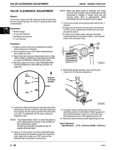
8. Slide feeler gauge between valve cap (A) and rocker arm to measure clearance. 14° BTDC
Direction of Engine Rotation
12° BTDC
1 TDC
T6105BF
5. Locate the rubber dust plug on the right side of the transmission tunnel, under the right side operator’s foot support. Pry the dust plug from the tunnel with a pry bar. The flywheel can be seen inside the inspection hole. NOTE: “Top Dead Center (TDC)” is when the piston is at it’s highest point of travel in the cylinder on the compression stroke. Number one cylinder is located at rear of engine (flywheel side).
9. To adjust valves, loosen lock nut (B) and turn adjusting screw (C) until blade of feeler gauge can be inserted between rocker arm and valve cap. Hold adjusting screw while tightening lock nut. 10. Recheck valve clearance after tightening lock nut. Valve Clearance Specification: . 0.15 – 0.25 mm (0.006 – 0.010 in.)
6. Using a 17 mm wrench, turn the crankshaft pulley while watching the flywheel inside the inspection hole. Align the number one TDC mark on the flywheel with the pointer on the tunnel.
3 - 24
4/5/01


