Service Repair Manual Models 299D2 XHP COMPACT TRACK LOADER

Product: COMPACT TRACK LOADER Model: 299D2 XHP COMPACT TRACK LOADER DX2 Configuration: 299D2 XHP & 299D2 Compact Track Loader DX200001 UP (MACHINE) POWERED BY C3.8 Engine Disassembly and Assembly C3.8 Engines for Caterpillar Built Machines Media Number -UENR0129-08 Publication Date -01/09/2015 Date Updated -19/05/2016 i06611151 Fuel Injection Pump - Remove SMCS 1251 011 Removal Procedure Table 1 Required Tools Tool Part Number Part Description Qty A 278 4138 Fuel System Protection Gp(1) 1 (1) This tool can only be used one time. Do not open the high pressure fuel system without allowing the fuel system to purge. After the engine has shut down, allow the fuel system to purge for ten minutes. This operating fuel system contains high pressure. Exposure to high pressure fuel can result in personal injury. Note: Use Caterpillar Electronic Technician (ET) to verify that the fuel system pressure is at zero before opening the fuel system. Note: Use Tooling (A) after any fuel line has been disconnected. 1. Ensure that number four piston is at the top center position on the compression stroke. Refer to Systems Operation, Testing and Adjusting, "Finding Top Center Position for No. 4 Piston". Previous Screen Shutdown SIS


Illustration 1 g02871416 2. Remove bolts (1) to remove cover (2) and the gasket. Illustration 2 g02871419 Illustration 3 g02890104 3. Mark the alignment of the pump gear and the idler gear for installation purposes. Remove nut (3). Use a suitable gear puller to remove gear (4).
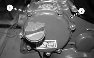
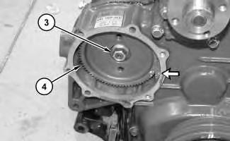
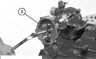
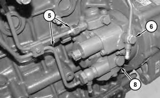
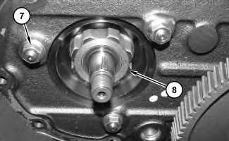
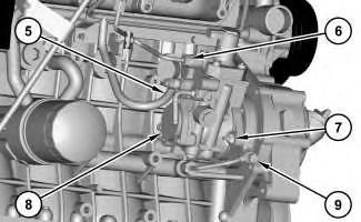
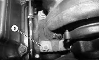
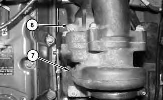
Illustration 4 g02871477 Illustration 5 g02871957 4. Disconnect tube assemblies (5) and tube assembly (6). 5. Remove nuts (7) to remove fuel injection pump (8). Copyright 1993 2019 Caterpillar Inc. All Rights Reserved. Private Network For SIS Licensees. Tue Oct 29 20:58:53 UTC+0800 2019
Product: COMPACT TRACK LOADER Model: 299D2 XHP COMPACT TRACK LOADER DX2 Configuration: 299D2 XHP & 299D2 Compact Track Loader DX200001 UP (MACHINE) POWERED BY C3.8 Engine Disassembly and Assembly C3.8 Engines for Caterpillar Built Machines Media Number -UENR0129-08 Publication Date -01/09/2015 Date Updated -19/05/2016 i06622292 Fuel Injection Pump - Remove SMCS 1251 011 S/N BL21 UP S/N - BL71 UP S/N - BY41 UP S/N - DX21 UP S/N - DX91-UP S/N - FD21 UP S/N - HP21 UP S/N MD21 UP Removal Procedure Table 1 Required Tools Tool Part Number Part Description Qty A 278 4138 Fuel System Protection Gp(1) 1 (1) This tool can only be used one time. Previous Screen Shutdown SIS
3. Mark the alignment of the pump gear and the idler gear for installation purposes. The alignment mark is shown at the location with the arrow in Illustration 2. Remove nut (4). Use a suitable gear puller to remove gear (3).
2.
Note: Use Tooling (A) after any fuel line has been disconnected.
Illustration
Illustration
Do not open the high pressure fuel system without allowing the fuel system to purge. After the engine has shut down, allow the fuel system to purge for ten minutes. This operating fuel system contains high pressure. Exposure to high pressure fuel can result in personal injury. Note: Use Caterpillar Electronic Technician (ET) to verify that the fuel system pressure is at zero before opening the fuel system.
1. Ensure that number four piston is at the top center position on the compression stroke. Refer to Systems Operation, Testing and Adjusting, "Finding Top Center Position for No. 4 Piston". 1 g03880533 Remove bolts (1) and cover (2). 2 g06050644
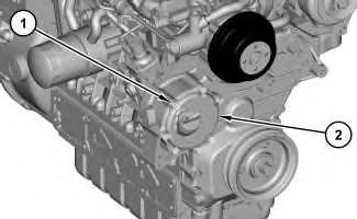
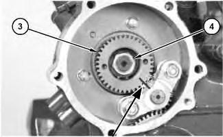
Illustration 3 g03880622 4. Disconnect tube assembly (6), tube assembly (9), and hose assembly (5). 5. Remove nuts (7) and fuel injection pump (8). Copyright 1993 2019 Caterpillar Inc. All Rights Reserved. Private Network For SIS Licensees. Tue Oct 29 20:59:49 UTC+0800 2019
Product: COMPACT TRACK LOADER Model: 299D2 XHP COMPACT TRACK LOADER DX2 Configuration: 299D2 XHP & 299D2 Compact Track Loader DX200001 UP (MACHINE) POWERED BY C3.8 Engine Disassembly and Assembly C3.8 Engines for Caterpillar Built Machines Media Number -UENR0129-08 Publication Date -01/09/2015 Date Updated -19/05/2016 i06275722 Fuel Injection Pump - Install SMCS 1251 012 S/N BL21 UP S/N - BL71 UP S/N - BY41 UP S/N - DX21 UP S/N - DX91-UP S/N - FD21 UP S/N - HP21 UP S/N MD21 UP Installation Procedure 1. Ensure that number four piston is at the top center position on the compression stroke. Refer to Systems Operation, Testing and Adjusting, "Finding Top Center Position for No. 4 Piston". Previous Screen Shutdown SIS
7.
Illustration 2 g06050644 Ensure the alignment mark shown in Illustration 2 is aligned between the pump gear and the idler gear. Replace the O ring seal between the pump and the engine. Line up the key of the supply pump gear and install the supply pump with a gear puller. Remove gear puller and tighten nut (4) to a torque of 64 ± 5 N·m (47 ± 3 lb ft).
Illustration 1 g03880622
4.
5.
3. Connect overflow return tube (5) to a torque of 16 N·m to 19 N·m (142 lb in to 168 lb in), tube assembly (6) to a torque of 23 N·m to 36 N·m (17 lb ft to 27 lb ft), and tube assembly (9) to a torque of 8 N·m to 12 N·m (71 lb in to 106 lb in).
2. Install fuel injection pump (8). Install nuts (7). Tighten nuts (7) to a torque of 25.5 ± 1.5 N·m (226 ± 13 lb in).
6.
Illustration 3 g03880533 8. Install cover (2) and bolts (1). Tighten bolts (1) to a torque of 25.5 ± 1.5 N·m (226 ± 13 lb in). Note: If a new supply pump is installed, a "Fuel Pump Calibration Override" must be performed using CAT Refer to Troubleshooting, UENR3423, "CAT ET Service Features, Fuel Pump Calibration". Copyright 1993 2019 Caterpillar Inc. All Rights Reserved. Private Network For SIS Licensees. Tue Oct 29 21:00:45 UTC+0800 2019
Product: COMPACT TRACK LOADER Model: 299D2 XHP COMPACT TRACK LOADER DX2 Configuration: 299D2 XHP & 299D2 Compact Track Loader DX200001 UP (MACHINE) POWERED BY C3.8 Engine Disassembly and Assembly C3.8 Engines for Caterpillar Built Machines Media Number -UENR0129-08 Publication Date -01/09/2015 Date Updated -19/05/2016 i06283437 Fuel Injection Pump - Install SMCS 1251 012 Installation Procedure 1. Ensure that number four piston is at the top center position on the compression stroke. Refer to Systems Operation, Testing and Adjusting, "Finding Top Center Position for No. 4 Piston". Illustration 1 g02871957 Previous Screen Shutdown SIS
Illustration 2 g02871477 2. Install fuel injection pump (8). Install nuts (7). Tighten nuts (7) to a torque of 25.5 ± 1.5 N·m (18.8 ± 1.1 lb ft). 3. Connect tube assembly (6) and tube assemblies (5). Tighten tube assembly (6) to a torque of 17.5 ± 1.5 N·m (154.9 ± 13.3 lb in). Tighten tube assemblies (5) to a torque of 29.5 ± 6.5 N·m (21.8 ± 4.8 lb ft). Illustration 3 g02871419 4. Install gear (4). Install nut (3). Tighten nut (3) to a torque of 63.5 ± 4.5 N·m (46.9 ± 3.3 lb ft). Illustration 4 g02871416
5. Install cover (2) and a new gasket. Install bolts (1). Tighten bolts (1) to a torque of 25.5 ± 1.5 N·m (18.8 ± 1.1 lb ft). Note: If a new supply pump is installed, a "Fuel Pump Calibration Override" must be performed using CAT Refer to Troubleshooting, UENR3423, "CAT ET Service Features, Fuel Pump Calibration". Copyright 1993 2019 Caterpillar Inc. All Rights Reserved. Private Network For SIS Licensees. Tue Oct 29 21:01:40 UTC+0800 2019
Product: COMPACT TRACK LOADER Model: 299D2 XHP COMPACT TRACK LOADER DX2 Configuration: 299D2 XHP & 299D2 Compact Track Loader DX200001 UP (MACHINE) POWERED BY C3.8 Engine Disassembly and Assembly C3.8 Engines for Caterpillar Built Machines Media Number -UENR0129-08 Publication Date -01/09/2015 Date Updated -19/05/2016 i06616120 Electronic Unit Injector - Remove and Install SMCS 1290 010 Removal Procedure Table 1 Required Tools Tool Part Number Part Description Qty A 5F 4764 Pry Bar 1 B 278 4138 Fuel System Protection Gp(1) 1 (1) This tool can only be used one time. Start By: a. Remove the valve mechanism cover. Do not open the high pressure fuel system without allowing the fuel system to purge. After the engine has shut down, allow the fuel system to purge for ten minutes. This operating fuel system contains high pressure. Exposure to high pressure fuel can result in personal injury. Note: Use Caterpillar Electronic Technician (ET) to verify that the fuel system pressure is at zero before opening the fuel system. Note: Use Tooling (B) after any fuel line has been disconnected. Previous Screen Shutdown SIS
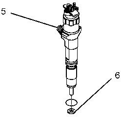
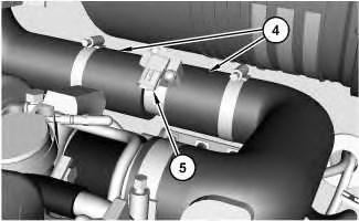
Note: If new injectors are installed or if injectors are switched between cylinders, refer to REHS9707 to install new injector trim codes in the Engine ECM and to register them on-line. Illustration 1 g06054347 1. Remove overflow joint screws (4) and overflow pipe (1). 2. Remove nut (2) to remove injector clamp (3). 3. Use Tooling (A) to remove electronic unit injector (5). Illustration 2 g06046967 4. Remove seal (6) from unit injector (5). 5. Repeat Steps 2 through 3 for the remaining electronic unit injectors. Installation Procedure 1. Install electronic unit injector (5) in the reverse order of removal.

End By: a. Install a new seal (6) onto electronic unit injector (5). Install electronic unit injector (5). b. Install nozzle clamp (3). Install nut (2). Tighten nut (2) to a torque of 26 ± 2 N·m (19 ± 1 lb ft). c. Install overflow pipe (1). Tighten overflow joint screws (4) to a torque of 11 ± 1 N·m (97 ± 9 lb in). a. Install valve mechanism cover. Copyright 1993 2019 Caterpillar Inc. All Rights Reserved. Private Network For SIS Licensees. Tue Oct 29 21:02:36 UTC+0800 2019
Product: COMPACT TRACK LOADER Model: 299D2 XHP COMPACT TRACK LOADER DX2 Configuration: 299D2 XHP & 299D2 Compact Track Loader DX200001 UP (MACHINE) POWERED BY C3.8 Engine Disassembly and Assembly C3.8 Engines for Caterpillar Built Machines Media Number -UENR0129-08 Publication Date -01/09/2015 Date Updated -19/05/2016 i07568873 Turbocharger - Remove and Install SMCS 1052 010 Removal Procedure Table 1 Required Tools Tool Part Number Part Description Qty A Loctite C5A Copper Anti Seize 1 Illustration 1 g02797291 Note: Machines with engine serial number 2HS00001 Up will have bolts, washers, and nuts. 1. Using a suitable stud puller or double nut remove nuts and studs (1). Previous Screen Shutdown SIS
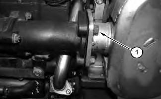
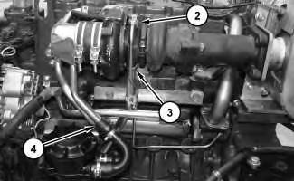
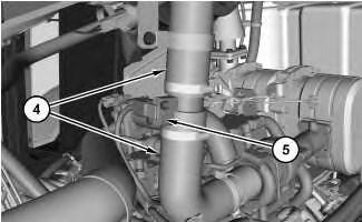
Illustration 2 g02797290 2. Remove tube assembly (2). Disconnect tune assembly (3) and hose (4). Illustration 3 g02797292 Illustration 4 g02797293 3. Remove nuts (5) and bolts (6). Remove turbocharger (7) and the gasket. Installation Procedure 1. Refer to Systems Operation, Testing and Adjusting, "Turbocharger Inspect" for more information. If the turbocharger is worn, the complete turbocharger must be replaced.
2. Install turbocharger (7) in the reverse order of removal. a. Apply Tooling (A) to the threads of bolts (6) and nuts (5). Copyright 1993 2019 Caterpillar Inc. All Rights Reserved. Private Network For SIS Licensees. Tue Oct 29 21:03:32 UTC+0800 2019
Product: COMPACT TRACK LOADER Model: 299D2 XHP COMPACT TRACK LOADER DX2 Configuration: 299D2 XHP & 299D2 Compact Track Loader DX200001 UP (MACHINE) POWERED BY C3.8 Engine Disassembly and Assembly C3.8 Engines for Caterpillar Built Machines Media Number -UENR0129-08 Publication Date -01/09/2015 Date Updated -19/05/2016 i06622343 Pressure Sensor (Mass Air Flow) - Remove and Install SMCS 1058; 1408; 1439 010; 1923 010; 7400 RemovalProcedure Removal Procedure Illustration 1 g03098499 1. Disconnect harness assembly (1). Remove clip (2). Loosen clamps (3). Note: For Skid Steer Loader, Multi Terrain Loader, and Compact Wheel Loader models built in 2012 and 2013, the two adjacent intake hoses may not be notched which sets the orientation of the sensor. If the intake hoses are not notched, then mark the position of the mass air flow pressure sensor for installation purposes. Previous Screen Shutdown SIS

Thankyouvery much for your Please Click Here. Then Get COMPLETE IfNOTE:MANUAL.NOWAITINGthereisnoresponse to click on the link above, please download the PDF document first and then clickonit.
Illustration 2 g06050677 Location for Skid Steer Loader, Multi Terrain Loader,and Compact Wheel Loader models. Illustration 3 g06050682 Location for Compact Wheel Loader models. 2. Disconnect hoses (4). Remove mass air flow sensor assembly (5). Illustration 4 g03098530 3. Remove screws (6). Remove mass airflow pressure sensor (7). Installation Procedure
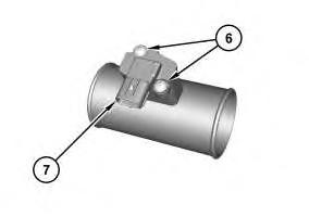
1. Install mass airflow pressure sensor (7) in the reverse order of removal. a. Tighten screws (6) to a torque of 1.17 N·m to 1.77 N·m (10.36 lb in to 15.67 lb in) Copyright 1993 2019 Caterpillar Inc. All Rights Reserved. Private Network For SIS Licensees. Tue Oct 29 21:04:28 UTC+0800 2019
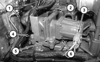
Product: COMPACT TRACK LOADER Model: 299D2 XHP COMPACT TRACK LOADER DX2 Configuration: 299D2 XHP & 299D2 Compact Track Loader DX200001 UP (MACHINE) POWERED BY C3.8 Engine Disassembly and Assembly C3.8 Engines for Caterpillar Built Machines Media Number -UENR0129-08 Publication Date -01/09/2015 Date Updated -19/05/2016 i04770346 Exhaust Gas Recirculation Valve - Remove and Install SMCS 108N 010 Removal Procedure Illustration 1 g02870501 1. Disconnect tube assembly (1), hose (2), and harness assembly (3). 2. Remove bolts (4) and nuts (5). 3. Remove exhaust gas recirculation valve (6) and the gasket. Installation Procedure 1. Install exhaust gas recirculation valve (6) and a new gasket in the reverse order of removal. Copyright 1993 2019 Caterpillar Inc. All Rights Reserved. Private Network For SIS Licensees. Tue Oct 29 21:05:23 UTC+0800 2019 Previous Screen Shutdown SIS