4 minute read
TROUBLESHOOTING CHART


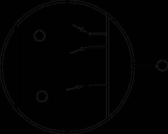
B 14° BTDC
12° BTDC
Advertisement
A TDC
1
Direction of Engine Rotation
C
7. Turn crankshaft and flywheel (using a 17 mm wrench on crankshaft pulley) until flywheel timing marks for cylinder No. 1 are visible through timing inspection hole. There are three marks side-byside. One is stamped with the number 1 (A) and is top-dead-center (TDC) for cylinder No.1. The other marks (B) are 12 and 14 degrees before top-deadcenter (BTDC). The 14 degree mark is the one to be used to set the timing of the injection pump.
Timing Fuel Injection Pump:
CAUTION
Fuel injection pump is capable of extremely high pressure. Do not place hands near high pressure outlet ports. Wear eye protection. Cover pump outlets with a cloth. Do not crank engine when high pressure lines are removed.
8. Open fuel shutoff valve on fuel filter. 9. The timing procedure must be performed with the fuel shutoff solenoid pulled in and holding open so a steady supply of fuel may be available to the injection pump. The key switch must be left ON during test to hold-in fuel solenoid.To pull the fuel solenoid in, the operator’s seat is tilted forward, and the seat switch is pulled UP to the defeat position. When fuel shutoff solenoid pulls in, an audible click is heard from the governor housing. 10.Turn the flywheel counterclockwise (as viewed from the flywheel end) until the timing tool straw has fuel showing. 11.Snap the straw with your finger until the level of the fuel, or a bubble, is set part way up the straw. This will be the point to watch for fuel movement. 12.Turn the crankshaft pulley clockwise (back) until the No. 1 cylinder top dead center (TDC) mark (A) and pump timing marks (B) have gone past the center mark of the timing hole (C) by at least 50 mm (2 in.).
NOTE: When running, the crankshaft turns counterclockwise (as viewed from operator’s seat). Number 1 cylinder is in the rear, closest to the flywheel.
13.Slowly turn the flywheel counterclockwise (as viewed from the flywheel end) until the fuel in the straw just starts to move. Stop rotating the flywheel the instant the fuel begins to move.
NOTE: If the fuel level does not change, the No. 1 piston may be on TDC of the exhaust stroke instead of the compression stroke. Turn flywheel one revolution and repeat Steps 12 & 13. Check that fuel shutoff solenoid is pulled in and battery is up to full charge.
14. Turn key switch OFF.
Specifications: Injection Pump Timing................................14° BTDC
Results:
• If Timing Is Not AccordingTo Specifications:
• Remove injection pump and shims. (See Injection
Pump Repair in this section.) • Increase shim pack thickness to retard injector timing, decrease thickness to advance timing. • Install injection pump and tighten nuts to 20 N•m
(177 lb-in.)
• Recheck timing.
• If Engine Performance RemainsPoor:
• Check air cleaners, fuel filter, fuel supply pump pressure, injector opening pressure, and cylinder compression before removing pump for service.
Check all timing gears for wear. Retest performance.
• IfPerformance Did Not Change:
• Have pump tested by an Authorized Diesel Service (ADS) Center. When reinstalling an injection pump sent out for service, use the same thickness of shim pack removed. If shim pack thickness is unknown or new pump is installed, replace with 0.8 mm (0.031 in.) shim pack thickness.
Reason:
To make sure that the injection pump timing is set to manufacturers specification.
Timing should not have to be checked unless one or more of the following have been replaced:
• Timing Gear(s) • Injector Pump • Injector Pump Camshaft • Timing Gear Housing
If one or more of these components have been replaced and timing must be checked, use the same procedure as FUEL INJECTION PUMP STATIC TIMING (NON EPA ENGINES) on page 28 in this section.
MX1339A
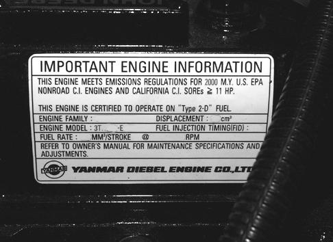
EPA engines have EPA compliance sticker on rocker arm cover as shown above.


