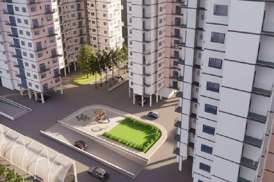
MULTIFAMILY HOUSING IN NASHIK

SITE AREA- 16154 SQ MT.


Development has drastically evolved the skyline of Nashik. This evolution in zones (nagars) consisting of basic resources and amenities. One such rapidly growing zone is Govind Nagar. May it be commercial buildings, best educational institutes, or shopping malls, Govind Nagar is surrounded by all. Thus the housing proposal aims to provide livable places that enrich sense of belonging and strengthen cultural identity of the place, which further conditions the user’s way of living.
The site in Govind nagar is in a locality which despite if being in a crowded area has open spaces in the immediate vicinity of the site. The site consists dense vegetation on the northern side which create buffer from the noise and chaos from the main road.
While designing the project the initial sketches generated with the same idea of providing open spaces in such a way that each cluster overlooks onto it.

SEM -8
5
CONTEXT
The main aim in the design to provide ample of light and ventilation to every unit. This achieved by orienting the tenements in a way that each unit has three sides open and overlooks into open areas provided in site.
Aspects which were thought about in designing the project: View for each tenement in each cluster. Ample of light ventilation for each unit ensuring cross ventilation
Hierarchy in the massing of buildings which can be seen while entering into the site.

HEIRARCHY IN MASSING
SITE PLAN LEGENDS-


1-3-4 BHK Cluster
2-2 BHK Cluster

3- 3-2 BHK Cluster
4- Amenity Space
5- Children’s play area
6- Amphitheatre
7- Swimming Pool
8-Overhead water tank
9- Garden area
3 6 9 15M 6
FIRST FLOOR LEVEL PLAN STILT LEVEL PLAN
-Parking
-Amenities

-Ramps to basement
-Play areas
-Units and Clusters -Amenities


The program includes 2, 3 and 4 bhk units which have been distributed in the site according to the users in the context. A hierarchy has been followed while giving heights to the buildings. The tallest being 20 floors followed by 15 and 10 floors. Each cluster is designed in a way that it has three sides open which ensure effective ventilation and ample of light in the spaces. Refuge areas have been provided on every 8th ,13th ,and 18th floors. Open areas including play areas, amphitheatre, and open ground. These areas are positioned in a way that the one or the façade of the cluster overlooks into these spaces and not into each other respecting their privacy.

SECTION WEST ELEVATION 7
NORTH ELEVATION

ELEVATION


 CLUSTER 3,4 BHK
CLUSTER 2 BHK
CLUSTER 3,4 BHK
CLUSTER 2 BHK
CLUSTER PLANS
CLUSTER 2, 3 BHK
8
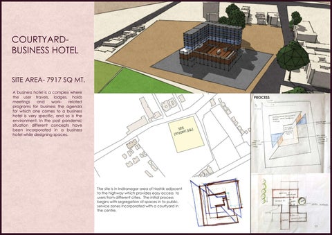
CREATIVE DIGNITY-CRAFT CENTRE FOR PHULKARI


SITE AREA- 2400 SQ MT.

Creative Dignity is a movement which focuses to provide relief, and rejuvenate the artisans in a bid to ensure their sustained prosperity. The agenda is to create awareness about the craft and the artisans, and to help the indigenous practice to modernize and prosper with the help of professional and designers. The idea is to generate spaces and built environment which can complement the social and cultural status of the craft. Also, offers an environment which gives them dignity they deserves. It also became a place where society and craft and professionals come together.
PHULKARI
Phulkari is brought to the Indian Subcontinent by the migrant Jat people of central Asia in ancient times. The embroidery is done with floss silk thread on coarse hand woven cotton fabric. The cloth primarily used and preferred by the women, was the home-spun, locally woven and dyed .
ROOF FORM


The roof is derived from the most popular symmetrical phulkari motifs formulated into 3D form with slope.
The site is in the foothills of pandavleni hills which provides a dynamic backdrop for the design. The site is adjacent to the national highway which marks the ease of access for the visitors. Being in vicinity of a hilly region the site has light contours of up to 2 meters.
SEM -4
9
NORTH ELEVATION
The Entry to the centre is through a corridor created by two stone walls 450 mm thick which creates a curiosity to the user to explore more. The circulation after the entrance is based on the concept of revealing in stages like petals of a flower which mean ‘Phul’ which is seen in the motifs of the craft Phulkari. The centre is divided into three zones from the entry i.e. Public, Semi private and private zone. The main aim while designing was to spread awareness about the craft and offer an environment that which gives Artisans dignity they deserve.
LEGENDS-
1-Parking

2-Entrance Lobby
3- Shop

4- Office
5- Guest Quarters

6- Exhibition Hall
7- Canteen
8- Kitchen
9- Toilets
10- Fabric making & dying Area
11- Workshop Area


12- Artisan’s Quarters GROUND FLOOR PLAN


SOUTH ELEVATION

4 6
2
10M
SECTIONS 10
CORPORATE TRAINING CENTRE FOR TATA INDUSTRY
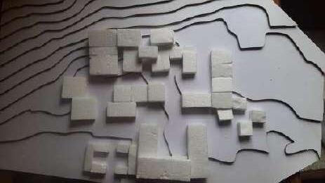
SITE AREA- 5.4 ACRE
A corporate management training program helps create synergy and collaboration within the business organization. The idea is to generate spaces and built environment which can complement the social and cultural status of the TATA group. It serves as a place where there is ease in connectivity and communication. It becomes a medium to upgrade and uplift the spirit of the user. The design responds to the site in a sensitive manner considering the context and geography.
The corporate training centre is designed with the idea of planning in a grid form and designing circulation pattern in a way which depicts the complete day routine of a trainee inn the training centre. The zone of heavy contours has been tackled by placement of auditoriums, conference rooms in the same region. Variations in volumes has been created through stacking of forms in same grid which id followed in plan.
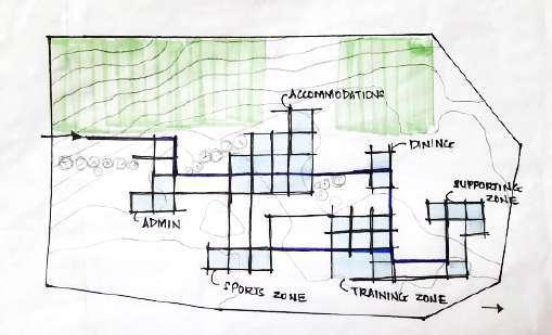

LEGENDS-
1-Entry Area
2-Library
3- Auditorium
4- Workshops

5- Meeting room
6- Sports room
7- Dining
8-Rooms
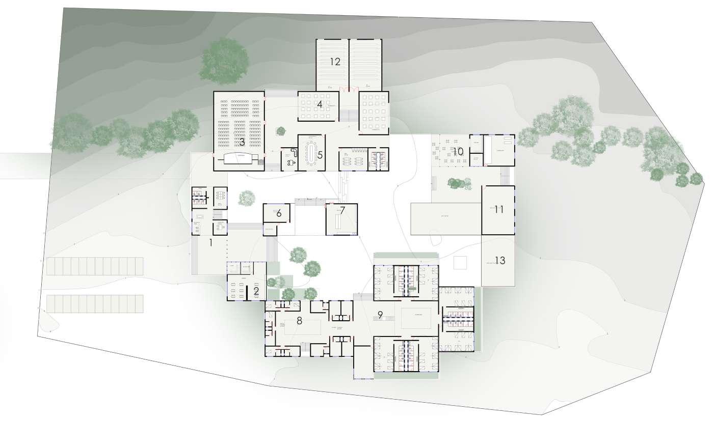
9- Dormitories
10- Cafe
11- Badminton court
12-Confrence
13-Caretakers accommodation
SEM -6
PLAN SECTION 14
SIGNATURE & STAMP YEAR/ SEM - THIRD YEAR YEAR/ V SEM MET's SCHOOL OF ARCHITECTURE SCALE DATE 02.10.2022 ROLL NO. 10 NAME APARNA KHAMBETE RESIDENCE SHEET CONTENTPLAN,SECTIONS AND DETAILS NOTES1. These general notes are not intended to replace specifications. 2. See specifications for requirements in addition to general notes. 3. The contractor shall supervise and direct the work and shall be solely responsible for all construction means, methods, procedures, techniques, and sequence. 4. The structure has been designed to resist design loads only as a Completed structure. Applications of construction loads to the partially completed structure shall be considered by the contractor and so included in the design of shoring, bracing, formwork, and any other supporting elements provided for construction of the structure. During erection and until all permanent connections are made, the contractor must provide temporary bracing for the structure in all directions. 5. The contractor shall compare structural sections provided by structural consultant with architectural sections and report any discrepancy to the architect prior to fabrication or installation of structural members. 6. Do not scale dimensions from drawings. The contractor shall request, from the architect, necessary dimensions not shown on the drawings. 7. Holes drilled for electrical, plumbing and fixtures shall not compromise the structural integrity of the construction done. 8. Unless otherwise indicated plan dimensions are to column grid on centerline nominal surface of masonry face of studs and face of concrete walls 9. The general contractor shall examine the architectural, mechanical, Electrical, and plumbing drawings for required openings as they shall be provided for whether shown on these drawings or not. 10. The designer shall not be responsible for plumbing, electrical or mechanical system design, size or location unless otherwise specified. 11. All work shall be erected plumb and true to line in accordance with best practices of the trade and manufactures recommendation for the particular item 12. All work shall comply with all state and local codes and ordinances and shall be performed to the highest standard of craftsmanship by journeyman of or appropriate trades. COPY RIGHT This document, ideas and design incorporated herein, as an instrument of professional service is the property of APARNA KHAMBETE, is not to be used in whole or part, for any other project without the written authorization of APARNA KHEMBETE. SHEET NO. - 1/3 1:200 1:20 NORTH SR NO. TYPE SIZE QUANTIT Y LINTEL LEVEL D1 1000x 2100mm 5 2100mm D2 900x 2100mm 3 2100mm D3 800x 2100mm 7 2100mm D4 1250x 2100mm 1 2100mm SD1 1500x 2100mm 2 2100mm SD2 2800x 2100mm 2 2100mm DOOR SCHEDULE WINDOW SCHEDULE TYPE SIZE QUANTITY SILL LEVEL LINTEL LEVEL W1 2800x120 0mm 5 900mm 2100mm W2 2000x120 0mm 5 900mm 2100mm W3 600x900m m 7 1200mm 2100mm W4 1800x120 0mm 1 900mm 2100mm C1 230x450 mm C2 450x230 mm C3 450x230 mm C4 230x450 mm C9 230x450mm C8 450x230mm C7 450x230mm C6 230x450 mm C15 230x450mm C25 230x450mm C26 230x450mm C27 230x450mm C23 230x450mm C17 230x450mm C12 230x450mm C13 450x230mm C18 230x450mm C24 230x450mm C29 230x450mm C14 450x230mm C19 230x450mm C30 230x450mm C31 450x230mm C20 230x450mm C10 230x450mm C21 450x230mm C5 230x450 mm C11 230x450mm C22 230x450mm C32 230x450mm 00,00 START FACE 225 4230 5960 8065 9545 9655 12155 13755 13885 C2,C3 C1,C4,C5 C6,C7,C8,C9, C10,C11 C12 C13,C14 C21 C16,C17, C18,C19, C20,C22 C22,C23 C25,C26,C27, C28,C29,C30,C32 C31 225 1840 3115 4890 5115 7120 8120 8230 11225 11335 12960 15465 16345 19190 21465 22850 C22,C29 C5,C11 C21 C20 C30 C4,C9 C14 C18,C24,C28 C13 C3 C7,C12,C17,C23,C27 C2 C16,C26 C1,C6 C15,C25 C19,C29 3225 C10 27000 C16 230x450mm C28 230x450mm 13415 C28 12960 C8 60 60 20 4000 200 20 720 20 120 300 20 100 20 690 20 30 40 300 410 20 20 150 20 20 350 20 150 120 50 50 60 460 50 170 50 20 230 20 330 60 190 20 480 20 60 70 240 90 3900 20 20 20 420 20 270 20 490 20 20 150 20 340 300 150 20 150 20 450 20 150 10 40 50 20 240 20 130 20 520 20 400 20 80 20 200 120 60 150 230 170 40 520 390 250 300 70 80 50 350 60 60 300 520 450 530 430 250 830 430 360 120 150 190 1010 200 370 730 740 430 90 60 40 150 390 50 60 20 70 60 30 130 80 600 20 400 10 150 160 END FACE 14000,00 END FACE 00, 23075 20 240 130 320 330 400 LIVING ROOM 5195 4885 mm) DINING 4000x3333 mm) KITCHEN 3510 3456 mm) BEDROOM 7155 4000 mm) CARETAKER'S ROOM 5000 3885mm) HOMESTAY ROOM 3885x4540 mm) ENTRANCE AREA COURTYARD 3945 2655 mm) BEDROOM 4000x6885 mm) UP UP UP 20 UP UP SFL 00 FFL 00 SFL 1000 FFL 1075 SFL 850 FFL 925 SFL 2320 FFL 2625 20 SFL 2650 FFL 2725 FFL 1075 SFL 2650 FFL 2725 SFL 2650 FFL 2725 SFL 1000 FFL 1075 SFL 2350 FFL 2625 SFL 2350 SFL 700 FFL 975 SFL 700 FFL 975 SFL 700 FFL 975 TOILET TOILET TOILET TOILET TOILET UP EAST ELEVATION +8200 +7300 +6250 +5050 +4750 +4150 +3100 +1900 +1000 +00 TERRACE PARAPET LEVEL SLAB LEVEL LINTEL LEVEL LINTEL LEVEL SLAB LEVEL LINTEL LEVEL SILL LEVEL PLINTH LEVEL GROUND LEVEL BALCONY PARAPET LEVEL 300 300 120 90 90 90 30 270 30 300 160 320 260 30 100 210 320 210 210 320 260 210 320 210 320 90 60 210 SECTION CC' SECTION AA' +10000 TERRACE LEVEL +11200 OVERHEAD WATERTANK LEVEL HOMESTAY ROOM CARETAKER'S ROOM TOILET TOILET HOMESTAY ROOM BALCONY STUDY ROOM LIVING ROOM BEDROOM 03 BEDROOM 01 HOMESTAY ROOM ENTRANCE LOBBY +7300 +4150 +1000 +00 SLAB LEVEL SLAB LEVEL PLINTH LEVEL GROUND LEVEL +7300 +4150 +1000 +00 SLAB LEVEL SLAB LEVEL PLINTH LEVEL GROUND LEVEL +10000 TERRACE LEVEL C1 C2 C3 C4 C9 C8 C7 C6 C15 C25 C26 C27 C23 C17 C12 C13 C18 C24 C29 C14 C19 C30 C31 C20 C10 C21 C5 C11 C22 C32 C16 C28 CENTRELINE PLAN GROUND FLOOR PLAN SFL 00 FFL 00 SFL 00 FFL 00 SFL 1000 FFL 1075 SFL 1000 FFL 1075 PANTRY 4115 3385mm) SFL 1000 FFL 1075 SFL 1000 FFL 1075 TREAD 300MM RISER=150 MM TERRACE TERRACE TERRACE TERRACE 150 220 120 120 220 30 60 150 240 30 10 D3 W3 200 A B' B A' D' C D C' SECTION AA' (1:20) SECTION CC' (1:20) 100 345 170 210 250 250 210 520 900 300 NAHANI TRAP DIVERTER TAP WC COUNTER TOP WASH BASIN GLASS PARTITION TILE DROP PLAN (TOILET DETAIL) (1:20) TOILET DETAILS WORKING DRAWINGS - RESIDENCE 15
ADVANCED BUILDING CONSTRUCTION AND SERVICES - SWIMMING POOL
HANDRAIL
LIGHT FIXTURE DETAIL@ 1:10
LIGHT CONTROL BOX

PCC BED (100MM THICK)
LIGHT FIXTURE (750 MM DEEP)
RCC RAFT SLAB
BOTTOM EDGE DETAIL @1:10
FRESHWATER INLET DETAIL@ 1:10
FRESH WATER INLET
FLOOR FINISH(CERAMIC TILESJOHNSON &JOHNSON 25mm x25mm)
B.B. COBA 200MM
EXTERNAL TANKING (SHAHBAD TILES 40MM THICK)
PCC BED(100MM THICK)
GUTTER DETAIL@ 1:10


PCC BED (100MM)
DRAIN PIPE GUTTER
BB COBA


EXTERNAL TANKING (SHAHBAD TILES 40MM THICK)
GRATING CERAMIC TILES(25 x 25 mm)

SIGNATURE & STAMP YEAR/ SEM - FOURTH YEAR/ VI SEM MET's SCHOOL OF ARCHITECTURE SCALE DATE 01. 10.2022 ROLL NO. 10 NAME APARNA KHAMBETE ABCS- I- SWIMMING POOL SHEET CONTENT PLAN, SECTIONS & ELEVATION NOTES 1. These general notes are not intended to replace specifications. 2. See specifications for requirements in addition to general notes. 3. The contractor shall supervise and direct the work and shall be solely responsible for all construction means, methods, procedures, techniques, and sequence. 4. The structure has been designed to resist design loads only as a Completed structure. Applications of construction loads to the partially completed structure shall be considered by the contractor and so included in the design of shoring, bracing, formwork, and any other supporting elements provided for construction of the structure. During erection and until all permanent connections are made, the contractor must provide temporary bracing for the structure in all directions. 5. The contractor shall compare structural sections provided by structural consultant with architectural sections and report any discrepancy to the architect prior to fabrication or installation of structural members. 6. Do not scale dimensions from drawings. The contractor shall request, from the architect, necessary dimensions not shown on the drawings. 7. Holes drilled for electrical, plumbing and fixtures shall not compromise the structural integrity of the construction done. 8. Unless otherwise indicated plan dimensions are to column grid on centerline nominal surface of masonry face of studs and face of concrete walls 9. The general contractor shall examine the architectural, mechanical, Electrical, and plumbing drawings for required openings as they shall be provided for whether shown on these drawings or not. 10. The designer shall not be responsible for plumbing, electrical or mechanical system design, size or location unless otherwise specified. 11. All work shall be erected plumb and true to line in accordance with best practices of the trade and manufactures recommendation for the particular item 12. All work shall comply with all state and local codes and ordinances and shall be performed to the highest standard of craftsmanship by journeyman of or appropriate trades. COPY RIGHT This document, ideas and design incorporated herein, as an instrument of professional service is the property of APARNA KHAMBETE, is not to be used in whole or part, for any other project without the written authorization of APARNA KHEMBETE. SHEET NO. - 2/ 3 1:100 SITE PLAN ALL DIMENSIONS IN MM OPENINGS SCHEDULE SRNO. TYPE SIZE QUANTITY LINTEL LEVEL 1 D1 900x2100mm 6 2100mm 2 D2 750x2100mm 20 2100mm 3 D3 1200x2100mm 2 2100mm 4 D4 1800x2100mm 1 2100mm 5 W1 700x1100mm 14 2100mm 6 W2 1200x 1200mm 2 2100mm 7 OP1 1900x 1200mm 2 2100mm 8 OP2 800x1200mm 2 2100mm 9 SD 1800x2100mm 1 2100mm NORTH CERAMIC TILES PCC RCC SOLING/ MURUM PAVING BRICK LEGENDS CHANGING ROOMS AND SHOWER (FEMALE) CHANGING ROOMS AND SHOWER (MALE) COACH ROOM FILTRATION AND PUMP ROOM ENTRANCE RECEPTION WAITING VIEWING AREA WARM UP AREA SECTION AA' P.C.C. BED (100 MM THICK) SHAHBAD TILES (BOX TYPE WATERPROOFING) 40MM THICK RCC RAFT SLAB 150 MM THICK (M350 GRADE) CHANGING ROOMS AND TOILETS DIVING BOARD FRESH WATER CHUTES LIGHT FIXTURE BALANCING TANK (2Mx 2Mx 2M) LANE LANE LANE LANE LANE A' A B' B RAMP WATER
DIVING BOARD
HDPS
GL +00 FFL +475mm LADDER
FFL +750mm FFL +475mm FFL +500mm FFL +500mm FFL +1050mm 1 2 3 4 5 6 7 8 9 A B C D E F G H J K L D1 D1 D1 D1 D1 D1 D2 D2 D2 D2 D2 D2 D2 D2 D2 D2 D2 D2 D2 D2 D2 D2 D2 D2 D3 D4 W1 W1 W1 W1 W1 W1 W1 W1 W1 W1 W1 W2 OP1 OP2 OP2 OP1 SD PLOT BOUNDARY D3 D2 C1 (450x230) C2 (450x230) C3 (450x230) C4 (450x230) C5 (450x230) C6 (450x230) C7 (450x230) C8 (450x230) C9 (450x230) C10 (450x230) C11 (450x230) C12 (450x230) C13 (450x230) C15 (450x230) C14 (450x230) C16 (450x230) C17 (450x230) C18 (450x230) C19 (450x230) C20 (450x230) C21 (450x230) C22 (450x230) C23 (450x230) -1560 -1660 -1510 -1225 -1200 00 +2000 +3115 -2170 RCC RAFT SLAB RCC RAFT SLAB PCC BED(100MM THICK) EXTERNAL TANKING (SHAHBAD TILES 40MM THICK) B.B. COBA 200MM FLOOR FINISH(CERAMIC TILESJOHNSON &JOHNSON 25mm x25mm) RUBBLE SOLING(230MM) MURUM FILLING
+3415 T-300mm R-150mm 4770 2890 IC IC IC IC W2 ENTRY
16
SIGNATURE & STAMP YEAR/ SEM FOURTH YEAR/ VI SEM MET's SCHOOL OF ARCHITECTURE SCALE DATE 02.10.2022 ROLL NO. - 10 NAME - APARNA KHAMBETE ABCS-1 PEB- INDUSTRIAL BUILDING SHEET CONTENTPLAN,SECTIONS AND DETAILS NOTES 1. These general notes are not intended to replace specifications. 2. See specifications for requirements in addition to general notes. 3. The contractor shall supervise and direct the work and shall be solely responsible for all construction means, methods, procedures, techniques, and sequence. 4. The structure has been designed to resist design loads only as a Completed structure. Applications of construction loads to the partially completed structure shall be considered by the contractor and so included in the design of shoring, bracing, formwork, and any other supporting elements provided for construction of the structure. During erection and until all permanent connections are made, the contractor must provide temporary bracing for the structure in all directions. 5. The contractor shall compare structural sections provided by structural consultant with architectural sections and report any discrepancy to the architect prior to fabrication or installation of structural members. 6. Do not scale dimensions from drawings. The contractor shall request, from the architect, necessary dimensions not shown on the drawings. 7. Holes drilled for electrical, plumbing and fixtures shall not compromise the structural integrity of the construction done. 8. Unless otherwise indicated plan dimensions are to column grid on centerline nominal surface of masonry face of studs and face of concrete walls 9. The general contractor shall examine the architectural, mechanical, Electrical, and plumbing drawings for required openings as they shall be provided for whether shown on these drawings or not. 10. The designer shall not be responsible for plumbing, electrical or mechanical system design, size or location unless otherwise specified. 11. All work shall be erected plumb and true to line in accordance with best practices of the trade and manufactures recommendation for the particular item 12. All work shall comply with all state and local codes and ordinances and shall be performed to the highest standard of craftsmanship by journeyman of or appropriate trades. COPY RIGHT This document, ideas and design incorporated herein, as an instrument of professional service is the property of APARNA KHAMBETE, is not to be used in whole or part, for any other project without the written authorization of APARNA KHEMBETE. SHEET NO. - 3/3 1:200 1:20 WINDOW SCHEDULE SR.NO TYPE SIZE QUANTITY LINTEL LEVEL 1 W1 1800X1200 21 2100 2 W2 2400X1200 2 2100 3 W3 900X1100 4 2100 DOOR SCHEDULE SR. NO. TYPE SIZE QUANTITY LINTEL LEVEL 1 D1 900x2100mm 5 2100 2 D2 700x2100mm 4 2100 3 D3 1800x2100mm 3 2100 4 Shutter Door 6000x3000mm 2 3000 NORTH ROOFING SHEET PCC RCC SOLING/ MURUM PAVING BRICK LEGENDS TOILETS UNLOADING RAW MATERIALS CANTEEN OFFICE WORKING FINISHED GOODS PRODUCTION UNIT 1 (24000mmx 54000mm) PRODUCTION UNIT 2 (18000mmx42000mm) C1 C2 C3 C4 C5 C6 C7 C8 C10 C11 W1 C13 C14 C15 C16 C17 C18 C19 C20 C21 C22 C23 C24 C25 C26 C27 C28 C29 C30 C31 C50 C51 C33 C34 C35 C36 C37 C39 C40 C41 C42 C43 C44 C45 C46 C47 C48 C49 CRANE BAY CRANE BAY 1 2 3 5 6 7 A B C D E F G H J PARKING ENTRANCE/SECURITY A A' FLOOR PLAN @1:200 C12 W1 W1 W1 W1 W1 W1 W1 W1 W1 W1 W2 W2 W1 W1 W1 W1 W1 W1 W1 W1 W1 W1 W3 W3 W3 W3 D1 D1 D1 D2 D2 D2 D2 D1 D1 D3 D3 D3 SD4 SD4 UNLOADING C1 C2 C3 C4 C5 C6 C7 C8 C9 C11 C13 C14 C15 C16 C17 C18 C19 C20 C21 C23 C25 C26 C27 C28 C29 C30 C31 C32 C33 C34 C35 C36 C37 C39 C40 C41 C42 C43 C44 C45 C46 C47 C48 C49 CRANE BAY CRANE BAY 1 2 3 4 5 7 A C D G H J STEEL COLUMN 600X 450MM BASE PLATE RAFTER RIDGE BRACING RIDGE PURLIN CRANE TRACK CRANE TRACK
CRANE TRACK PURLIN RIDGE VENTILATOR SECTION STANCHION (450X 600 mm) TREMIX FLOORING (150mm thick) BRICK WALL (230 mm thick) GIRT GALVALUM SHEET (1200x2400mm) PRODUCTION UNIT 1 PRODUCTION UNIT 2 WORKING B A C32 C50 C51 LOADING PLATFORM UNLOADING PLATFORM IC T-300mm R-150mm T-300mm UP UP (600X 450MM) (600X 450MM) (600X 450MM) (600X 450MM) (600X 450MM) (600X 450MM) (600X 450MM) (600X 450MM) (600X 450MM) (600X 450MM) (600X 450MM) (600X 450MM) (600X 450MM) (600X 450MM) (600X 450MM) (600X 450MM) (600X 450MM) (600X 450MM) (600X 450MM) (600X 450MM) (600X 450MM) (600X 450MM) (600X 450MM) (600X 450MM) (600X 450MM) (600X 450MM) (600X 450MM) (600X 450MM) (600X 450MM) (600X 450MM) (600X 450MM) (600X 450MM) (600X 450MM) (600X 450MM) (600X 450MM) (600X 450MM) (600X 450MM) (600X 450MM) (600X 450MM) (600X 450MM) (600X 450MM) (600X 450MM) (600X 450MM) (600X 450MM) GL +450 FFL+600 (4500x 5500) D3 RAW MATERIALS LOADING PLATFORM UNLOADING PLATFORM ROOFING SHEET B B' GUTTER SECTION A A' I- SECTION -(600X 450MM) BASE PLATE CLEAT SUPPORT FOUNDATION BOLTS ANCHORED TO FOOTING SECTION -(600X 450MM) BASE PLATE CLEAT SUPPORT FOUNDATION MURUM FILLING RUBBLE SOLING 230 MM CLEAT SUPPORT SECTION -(600X 450MM) GIRT (150 x 100mm) BOLTS FIXED TO ROOFING MATERIAL ROOFING MATERIAL RIDGE OPENING FOR LIGHT BOLTS ANCHORED TO FOOTING RIDGE VENTILATOR DETAIL @1:20 GIRT DETAIL @1:20 FOOTING DETAIL@1:20 ADVANCED BUILDING CONSTRUCTION AND SERVICES -PRE ENGINEERED BUILDING 17
ROOF PLAN @1:200
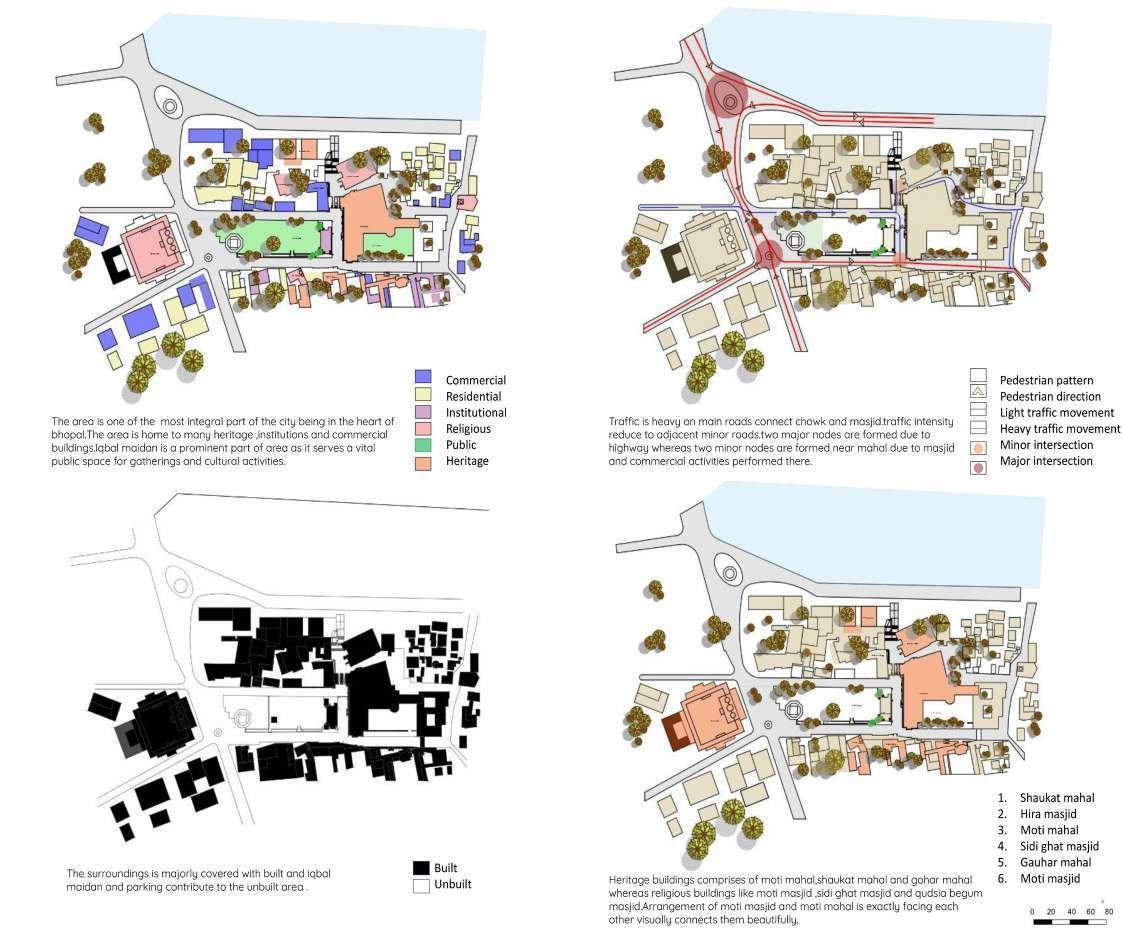
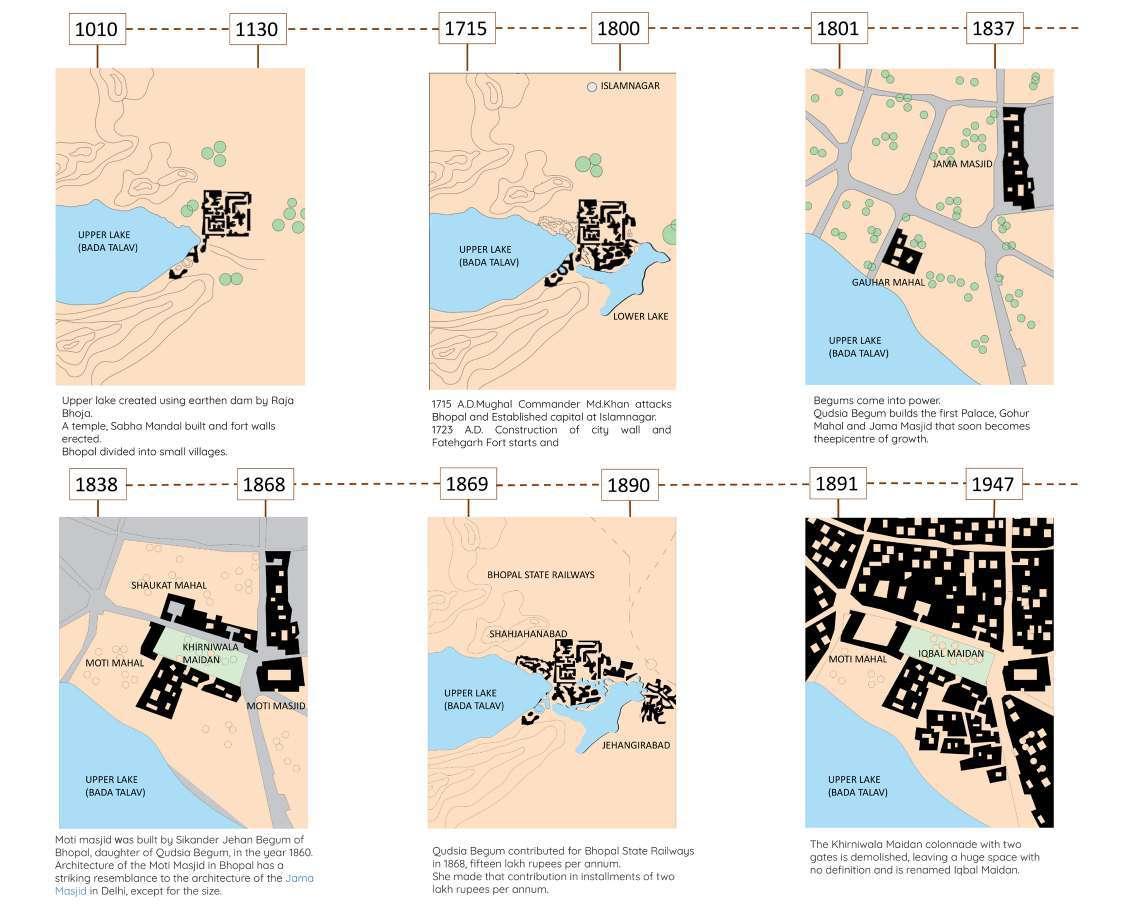
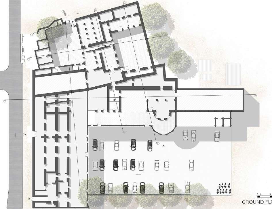
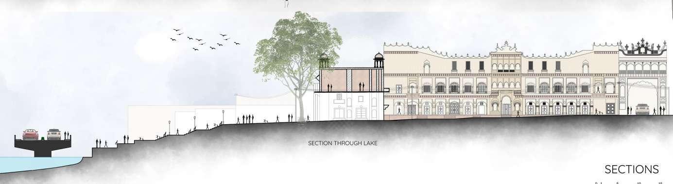
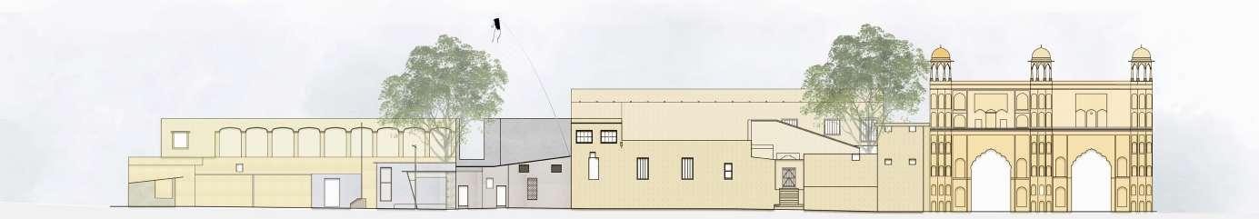
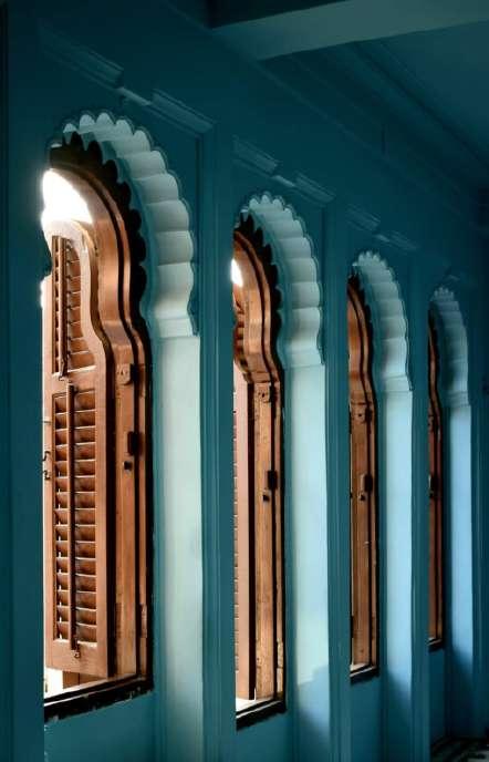
BHOPAL DOCUMENTATION - (JANUARY 2023) 18


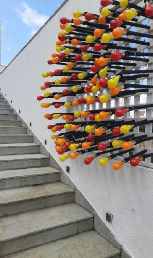


INTRESTS AND EXPERIENCES 19