Systems in Architecture
Acoustics

Individual Task 4XA3 Pages Al Imon Mohammed 19121107


Individual Task 4XA3 Pages Al Imon Mohammed 19121107

The following project will involve adapting the above tower block to a more habitable space. the focus on this project is acoustics so an overall wider analysis into the area has been done. You can see from the noise map the area is quiet and this was also proven true on a site visit. However due to the aim of the project being to regenerate the area noise will increase. So as to not disturb the locals the apartments need to be updated to better standards. The are some structural obstacles which make this a little tricky.
Before bringing in the intervention, the existing wall builds were drawn to see where they can be improved. These were adjusted through the use of Approved document E and discussions. Red highlights all the changes required. These changes must be applied in external and party walls. the concrete columns without the cavity stop alongside not having enough mass required a more bespoke system with resilient clips and furring’s. All the details below are now compliant with document E.
Masonry (aprox cavity 75mm)
Loadkore felt
Concrete column (aprox 685x150)
Plasterboard (Aprox 10mm)
Resilient Sound Isolation clip with with resilient steel furring. creates 45mm spacing
9mm OSB
13mm Plasterboard
Detail F (Section) at 1:20
Using BRE Sound Control for Homes and precedents to develop a floating floor with a resilient layer for the existing slabs.
Flooring (aprox 10mm)
70mm screed (inteded to have underfloor heating
16mm rockbill board
Plasterboard
50mm acoustic insulation
Masonry
Concrete Slab (aprox 150mm) with lintel

2x 3mm REGUPOL Resilient underscreed
12mm Plasterboard
9mm OSB
Resilient Furring
Resilient Sound Isolation clip
Gap to let materials expand Flooring Acoustic sublayer
22mm underfloor heatingwith 150mm centres (by ONEBOARD)
45mmx45mm Battens
Masonry (aprox cavity 75mm)
Loadkore felt
Concrete column (aprox 685x150)
Woodwool
insulation
Plasterboard (Aprox 10mm)
Masonry (aprox cavity 75mm)
Loadkore felt
Plasterboard (Aprox 10mm)
Improved window design (see detail 1:10 Detail on right)
25x45mm Batten
13mm plasterboard. OSB can be added to improve sound isolation
Exploded axonometric for improvements to single glazing window (Detail B) at 1:10
12mm OSB or plywood against rendered wall
minimum 25mm thick wooden block to create space. Rubber spacer can be used to improve acoustic quality
12mm Perforated plywood. Perforations can be customised for aesthetic of household aswell as performance.
Original Single glazing window frame
Secondary glazing in front of original window to reduce outdoor airborne noise.
Plasterboard (Aprox 10mm)
Precast concrete wall
9mm OSB
13mm Plasterboard
Plasterboard (Aprox 10mm)
Wall Studs (aprox 90mm)

The 1:10 model from design exploration was used as the precedent to develop the parasitic capsule.
There is a subtle outline on the drawing to represent key parts of the capsule’s structure.


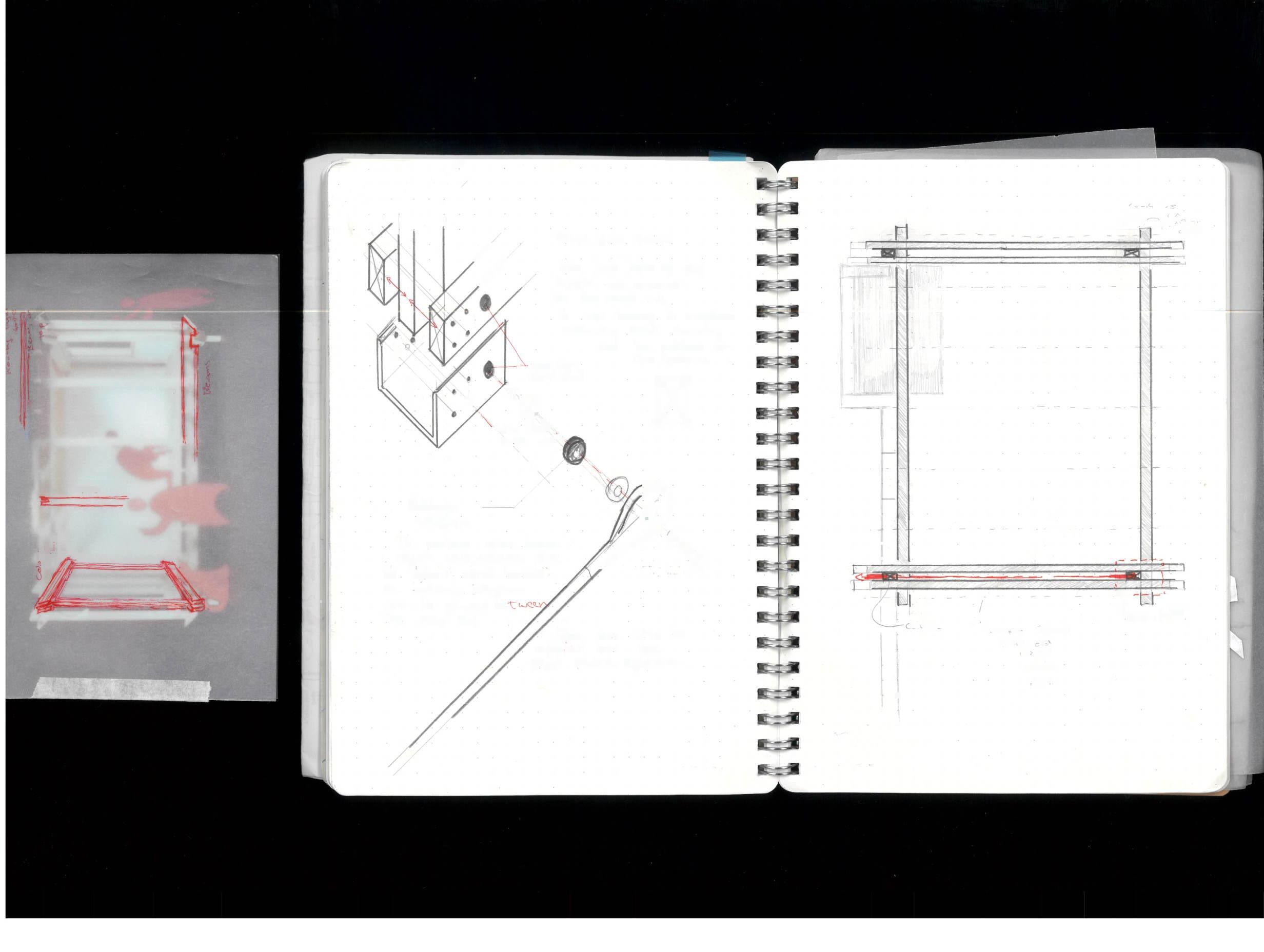
The plans were redrawn to include updates required on the party walls however these were applied on all the internal walls as well. The key difference is the transition from tower lock to timber capsule. The frame has an external wall within itself and an independent frame was used alongside the addition of a cavity stop with the existing bricks to reduce noise.
The other concept developed wad the steel rebar and steel plate to hold up the capsule. Noise from lateral winds could transfer onto the apartment. To slightly reduce this neoprene will be used on the top plate (sketch on right) and a rubber washer between the steel shoe (left).
1m 0.5m 0m
Apartment B section with applied intervention 1:20
at 1:50
If you look at the section the capsules will be sitting on top of the existing concrete balcony and supported with steel rods on either side. If required bracing will be used below. All this directly touching the concrete slab which is an extension (cantilever) of the main floor will make transferring impact noise from above below. To reduce this 150mm min. of acoustic insulation is used, Like other walls OSB is placed before plasterboard. The system form the goldsmith precedent is replicated somewhat here. Using I joists to create a floating floor and spacing out the insulation and the cavity. To keep the changing levels of the primary structure different timber sections are used to make sure the floors are level and have a resilient layer below.
Impact noise transferring from concrete slab to apartment below.
Extrium.co.uk. Available at: http://www.extrium.co.uk/noiseviewer.html. www.continal.co.uk. (n.d.). OneBoard® structural system | Continal Underfloor Heating. [online] Available at: https://www.continal.co.uk/system/oneboard [Accessed 13 Mar. 2024].
Soundstop.co.uk. (n.d.). GenieClip RST. [online] Available at: https://soundstop.co.uk/products/genieclip-rst?gad_ source=1&gclid=CjwKCAiAivGuBhBEEiwAWiFmYQIX2Wck2peYjO8ZJaRH4zfrBT_cPJBf7CZNuuLIyF-236bscCN1bhoC7l4QAvD_BwE [Accessed 13 Mar. 2024].
Ernst Neufert, Neufert, P., Johannes Kister, Sturge, D. and Luhman, N.J. (2019). Architects’ data. Chichester, West Sussex: John Wiley & Sons, Ltd ; Hoboken, Nj.