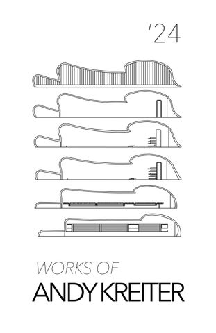
ANDY KREITER
2022 - CURRENT
2016 - 2020
EDUCATION
University of Oregon, M.ARCH Masters of Architecture
University of Missouri, B.S HES Architectural Studies
WORK EXPERIENCE
2023- CURRENT
2021 - 2022
2020 - 2021
2020
2018 - 2020
2020
2016 - 2019
2016 - 2019
2018
2014
DMA - Architectural Intern
CIDA Architecture - Architectural Intern
Roche Bobois - 3D Specialist
H.U.D - Subcontractor (Promotional Ad Producer)
Research Assistant - HES (College of Human Environmental Sciences)
RECOGNITION
VADS Applied Design Winner
HES Dean’s List
SEC Honor Roll
Visual Arts Design Showcase (VADS) Finalist
Scholastic Silver Key Award
EXTRA CURRICULAR
2023- CURRENT
2023
2019-2020
2019-2020
2016-2019
DSU (Design Student Union) Member
Sandpoint, ID Urban renewal competition
- Contract work for w/ Skylab Architecture
P.U.R.E Research
- Application of VR in Diving, Visualization Simulation
Manager - Mizzou Swim & Dive
D1 Student Athlete - Mizzou Diving
4
ajkreiter03@gmail.com
Beaverton, OR
andykreiter @
(480).619.2639
LANGUAGES
ENGLISH Fluent
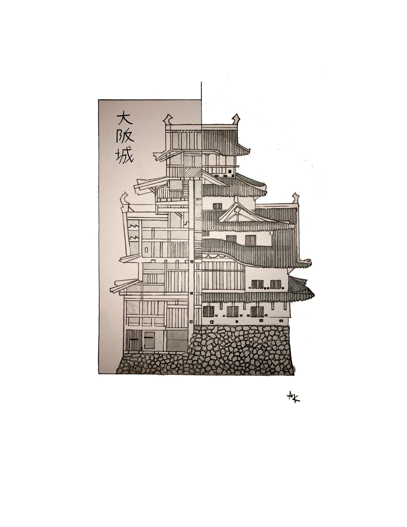
JAPANESE
Daily Conversation Level
SKILLS
MODELING RENDERING
• SketchUp
• 3ds Max
• ACAD
• Revit
• Twin Motion
• Enscape
• Rhino
• UE-4/5
POST PRODUCTION Ai
• Photoshop
• Illustrator
• InDesign
• AfterEffects
• CS beta
• Midjourney
• Runway
• EvolveLab

PROFESSIONAL WORKS
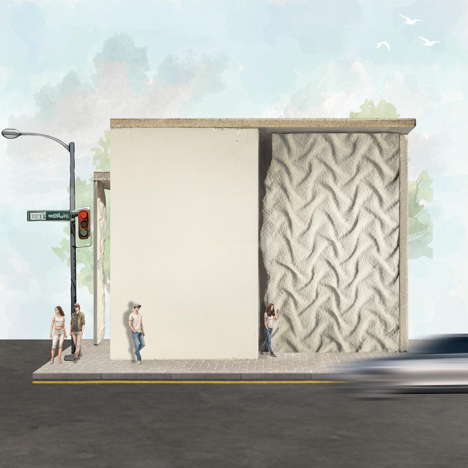
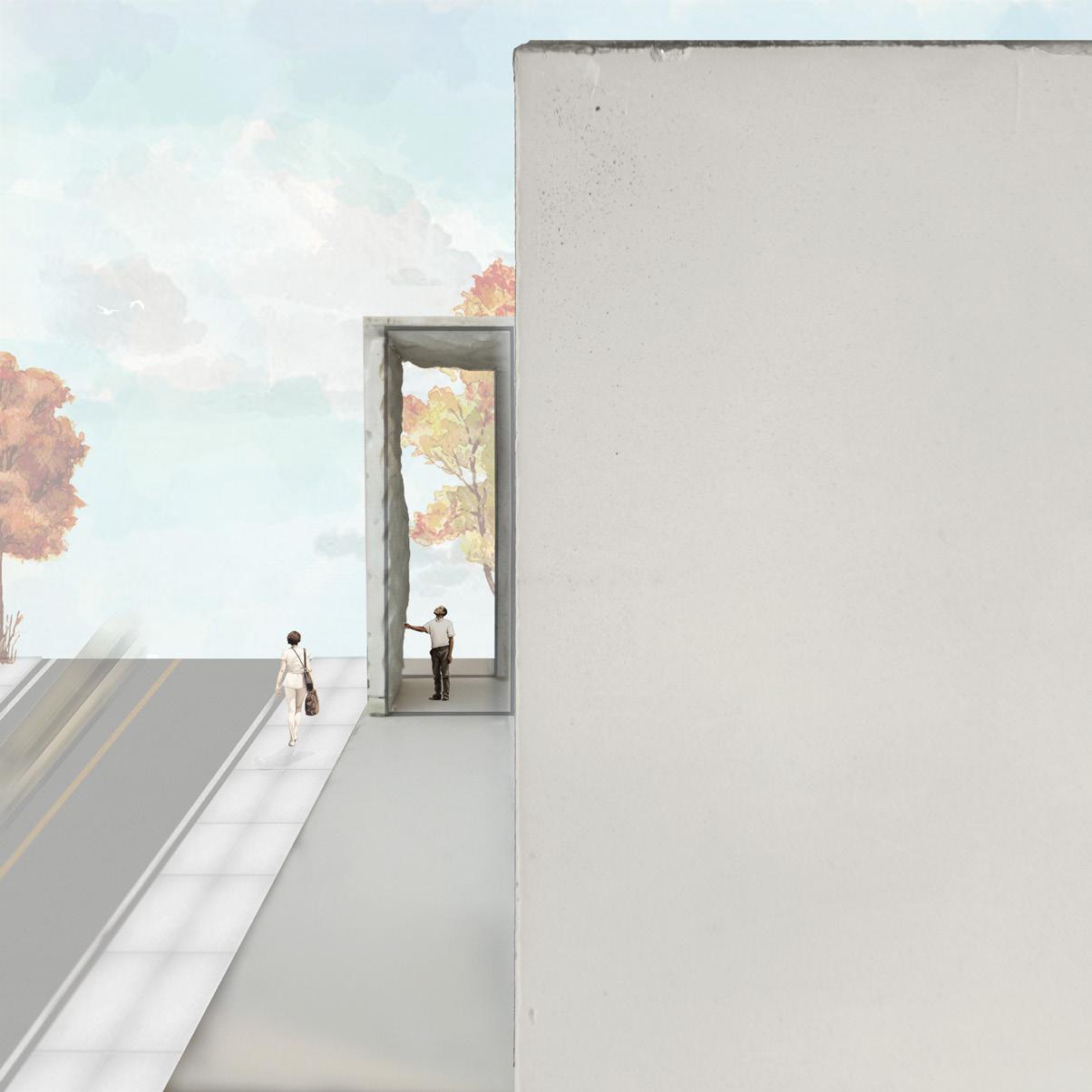
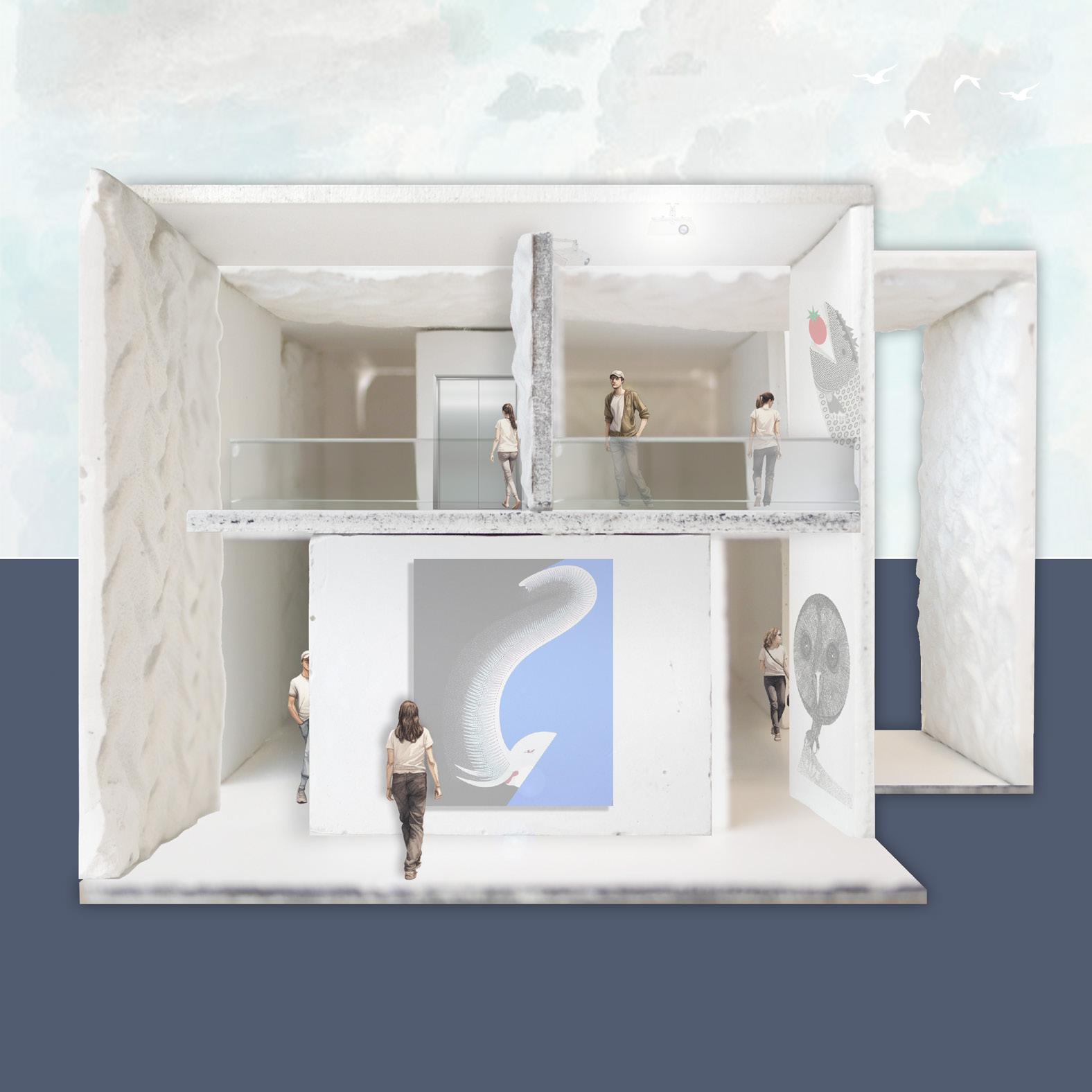
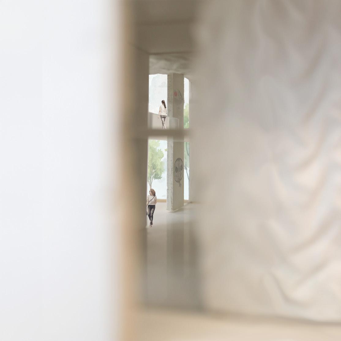
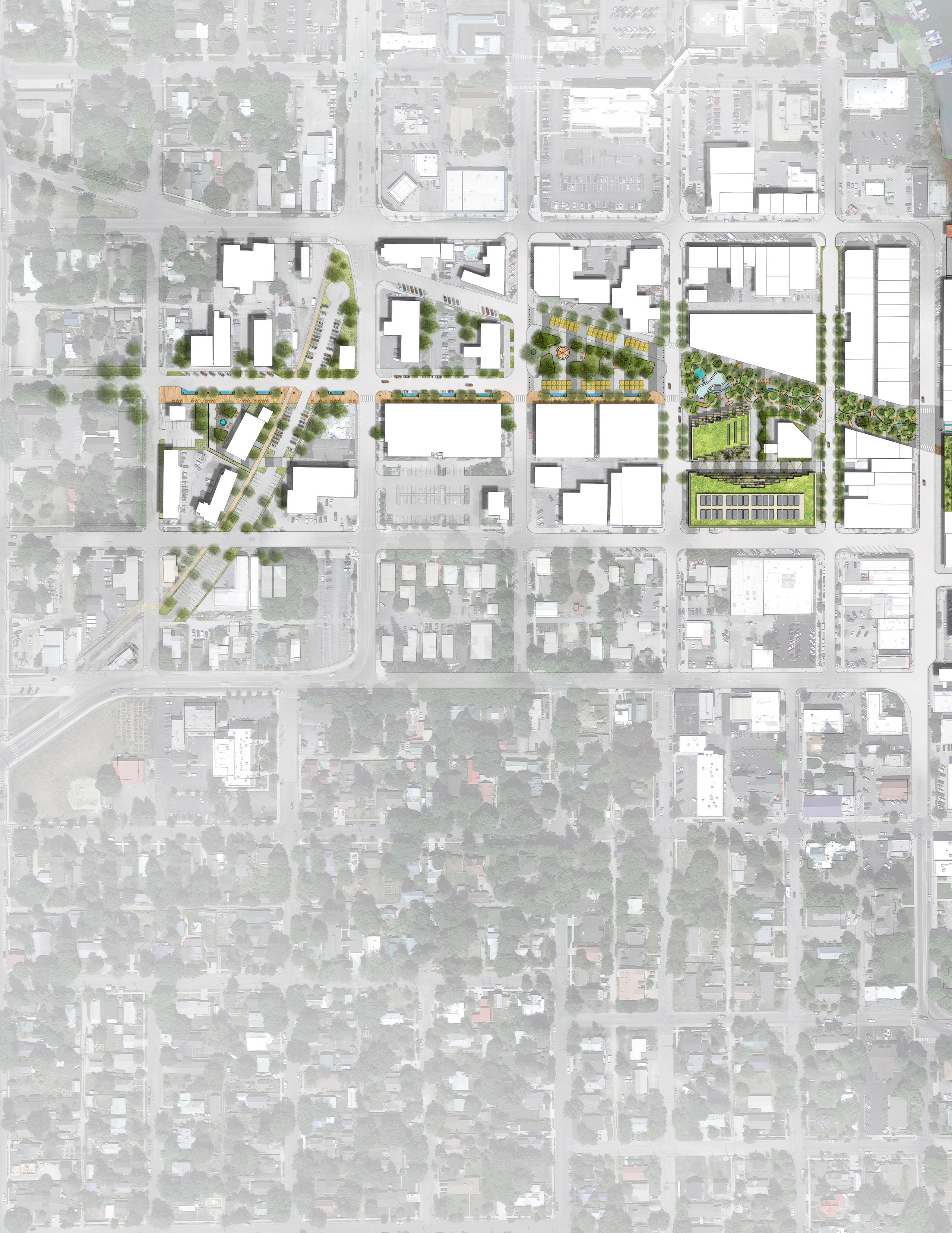
SKYLAB COLLAB ‘23
This RFP was for an urban renewal master-plan of Sandpoint, Idaho. Working under DMA, we were put on the competition team as consultants for SKYLAB, along with others such as PAE, PLACE and LEAD PENCIL.
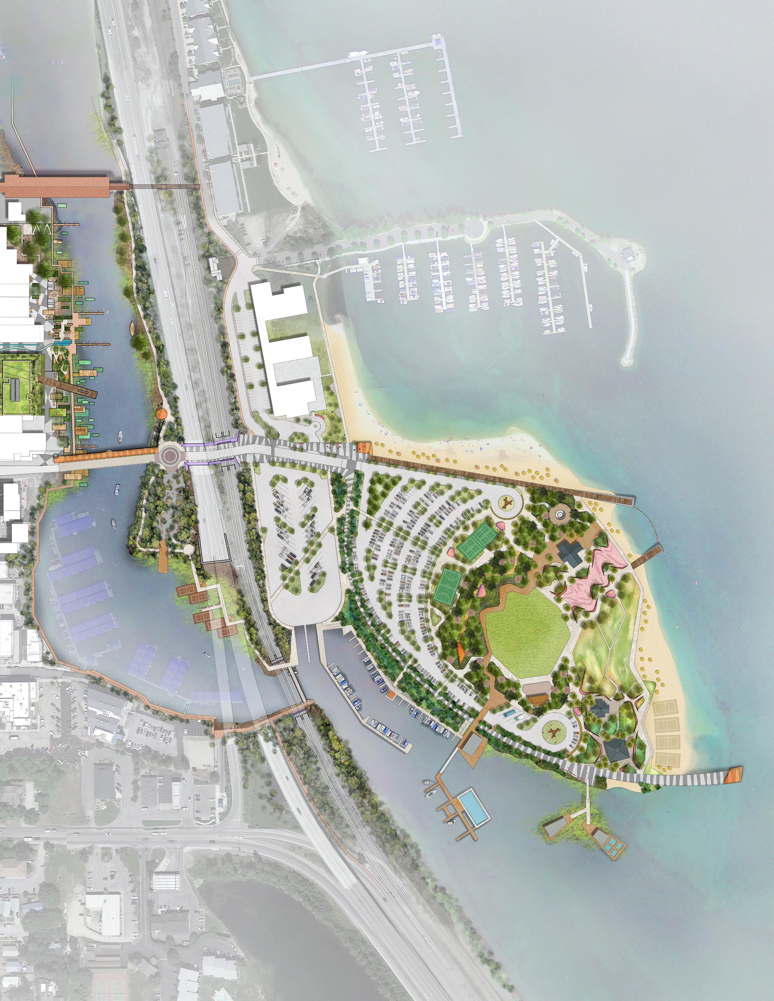
64 Vision

SCAN FOR FULL PRESENTATION
Renovated Street Sections
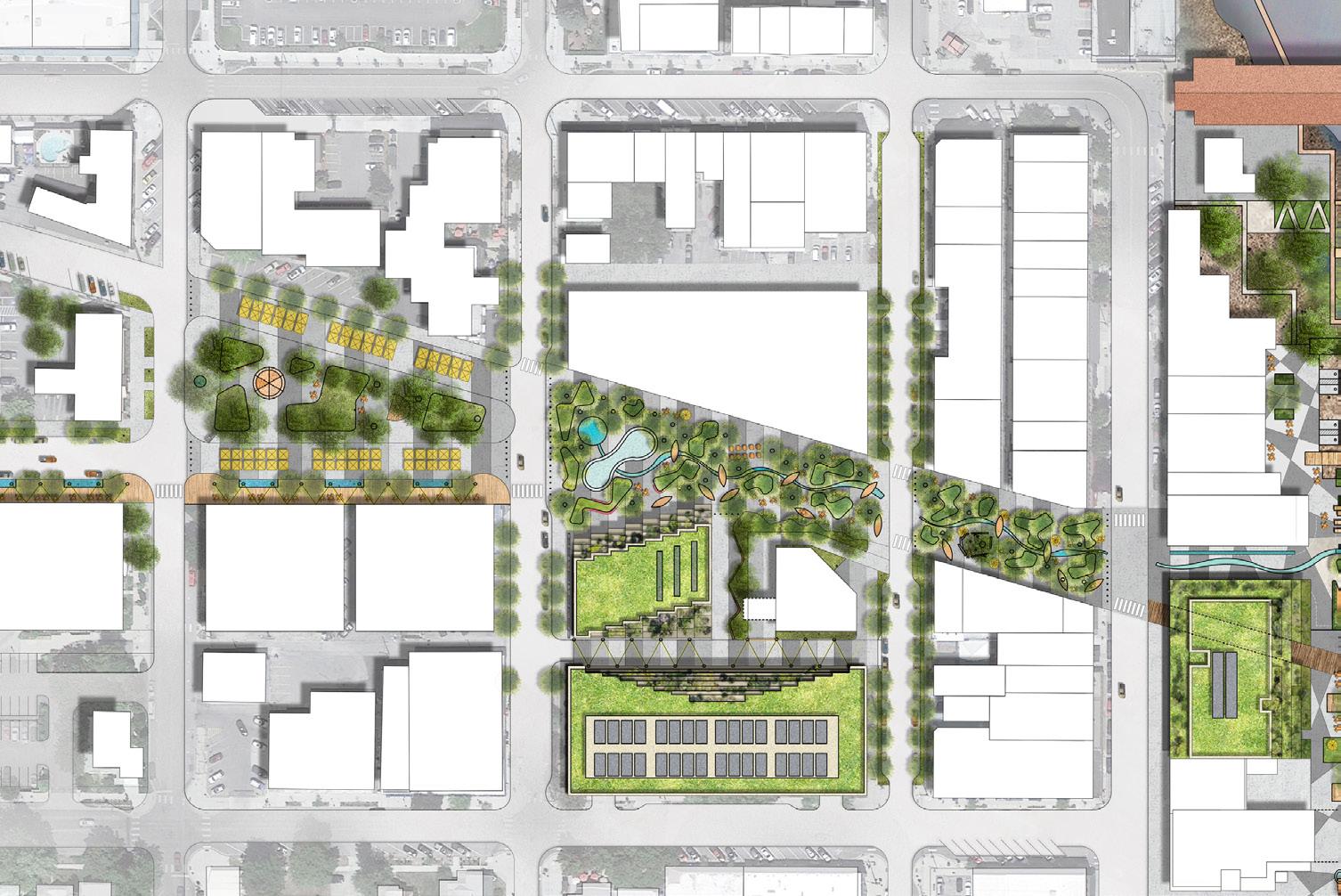
MAINST
My role in the competition was to visually interpret the zoning codes and develop street sections.
26
01 02 03 01 S. 3RD N. 2ND N. 1ST N. 4TH CEDAR ST CHURCH ST
HYDRAULIC BOLLARDS MARKET BOARDWALK COMMERCIAL A ZONE COMMERCIAL A ZONE SIDEWALK MULTI-MODAL & SHUTTLE SHARE PATH STORM WATER PLANTER FARMIN PARK MARKET 12’-6” 6’-0” 35’-6” 12’-0” 12’-0” 30’-0” 35’-6” 6’-0” 12’-6” FARMIN PARK HYDRAULIC BOLLARDS MARKET BOARDWALK COMMERCIAL A ZONE COMMERCIAL A ZONE SIDEWALK MULTI-MODAL & SHUTTLE SHARE PATH STORM WATER PLANTER FARMIN PARK MARKET 12’-6” 6’-0” 35’-6” 12’-0” 12’-0” 30’-0” 35’-6” 6’-0” 12’-6” FARMIN PARK OAK ST 31
Other contributions include recreating a detailed zoning map that highlighted the local historical zones (see pg. 69 of full RFP)
02 03 SIDEWALK MULTI-MODAL SHARE PATH RE-WILD PLANTER SIDEWALK PUBLIC RESTROOMS NEW INFILL DEVELOPMENT FOOD TRUCK POD DARK SKY STREET LIGHTING NEW INFILL DEVELOPMENT ICE RINK SOURCE FOUNTAIN 12’-6” 14’-6” 8’-0” 35’-0” 30’-0” 8’-6” 12’-6” 10’-0” JEFF JONES SQUARE SIDEWALK MULTI-MODAL RE-WILD PLANTER SIDEWALK PUBLIC RESTROOMS NEW INFILL FOOD TRUCK POD DARK SKY STREET LIGHTING NEW INFILL ICE RINK SOURCE 12’-6” 14’-6” 8’-0” 35’-0” 30’-0” 8’-6” 12’-6” 10’-0” SAND CREEK SIDEWALK MULTI-MODAL SHARE PATH RE-WILD PLANTER STORM WATER PLANTER COMMERCIAL A ZONE 12’-0” 6’-0” 8’-0” 14’-0” 12’-0” LANDMARK VIEW UNDERGROUND UTILITIES COMMERCIAL A ZONE NEW INFILL DEVELOPMENT RE-WILDING BLOCKS - 2ND/1ST AVE SAND CREEK SIDEWALK MULTI-MODAL SHARE PATH RE-WILD PLANTER STORM WATER PLANTER COMMERCIAL A ZONE 12’-0” 6’-0” 8’-0” 14’-0” 12’-0” LANDMARK VIEW UNDERGROUND UTILITIES COMMERCIAL A ZONE NEW INFILL DEVELOPMENT RE-WILDING BLOCKS - 2ND/1ST AVE 32

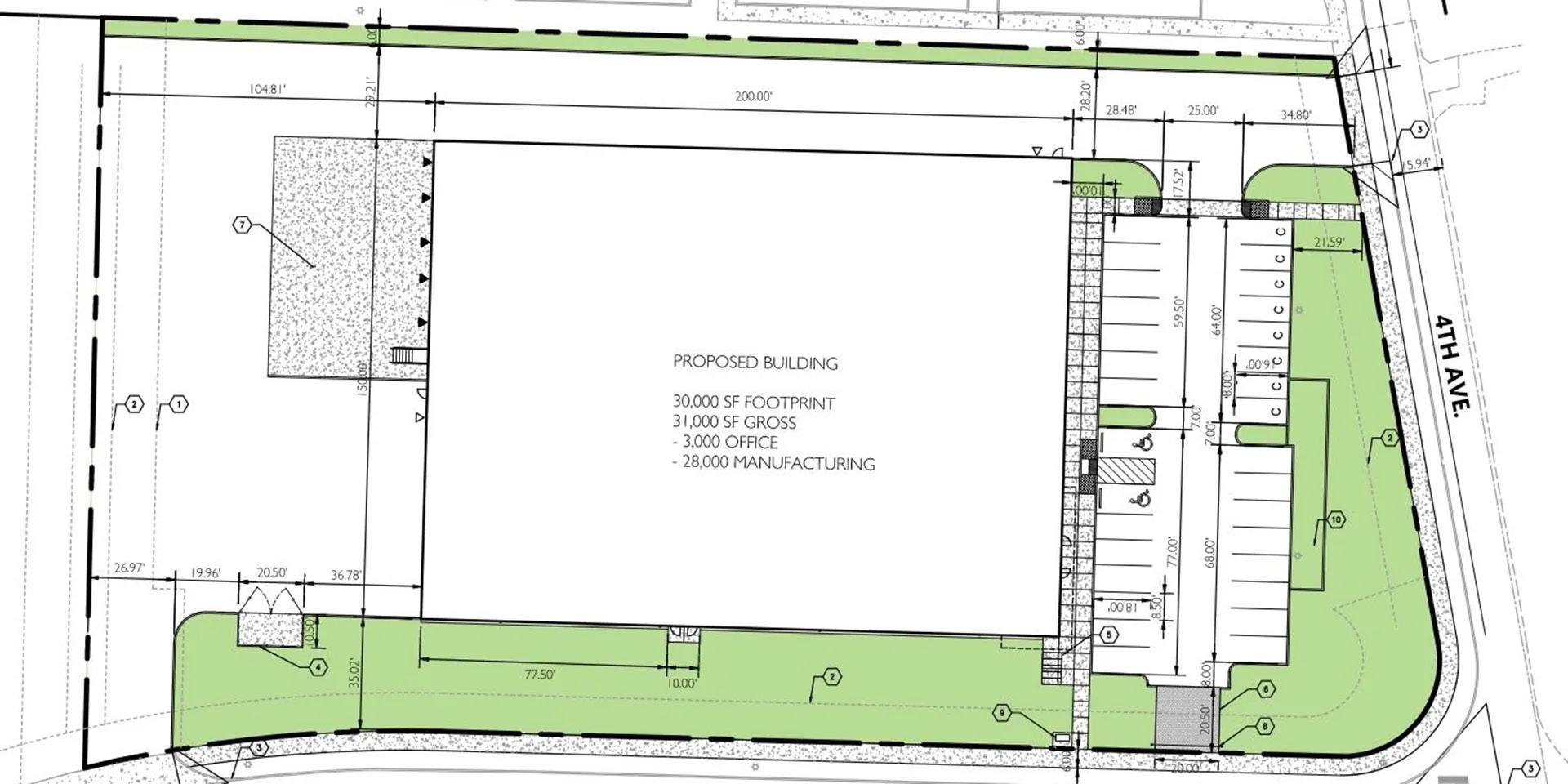
LUCKY FOODS
CIDA ‘20
• COMMERCIAL CD SET
• 31,000 SF
• CONCRETE TILT-UP
• REVIT / ENSCAPE
OREGON CITY, OR
28

SHEET LIST No. SHEET NAME CS1 AND CODE SUMMARY ZONING COMPLIANCE INFORMATION 1. ARCHITECTURE A1 FLOOR PLAN A2 ELEVATIONS A3 SECTIONS A4.1 DETAILS CS2 SITE PLAN A4.2 DECK DETAILS A4.3 STAIR DETAILS Owner Scale: 7412 SE HARMONY DR. MILWAUKIE, OR 97222 JORGE CHAVEZ 1014 NE LIJA LOOP PORTLAND, OR 97211 PERMIT SET Set: CHAVEZ Date: 08/14/23 Drawn by: Checked by: AK DM 11/15/2021 12:05:00 PM CHAVEZ ADDITIONS DMArC A R C H I T E C T P L A N N N G D E S G N 325 NE Graham St Portland, OR 97212 CODE SUMMARY CS1 JOB DESCRIPTION SEPARATE / DEFERRED PERMITS- ELECTRICALZONING INFORMATION PROPOSED CODE ZONE NO CHANGE R-7 MIN LOT SIZE NO CHANGE 10 acres MAX HEIGHT <35' 35' MAX SETBACK NO CHANGE NONE MIN FRONT SETBACK NO CHANGE 15' MIN SIDE SETBACK NO CHANGE 5' SITE INFORMATION 7412 SE HARMONY DR. MILWAUKIE, OR 97222 LOT COVERAGE: FRONT PORCH ADDITION 108 SF 120 SF APPLICABLE CODES 2021 OREGON RESIDENTIAL SPECIALTY CODE (ORSC) 2021 OREGON ELECTRICAL SPECIALTY CODE 2019 OREGON MECHANICAL SPECIALTY CODE STORMWATER MANAGEMENT N ORSC CH. 11 ENERGY EFFICIENCY PROJECT IS (4) WOOD FRAMED STRUCTURES ON AN EXISTING RESIDENTIAL PROPERTY. NEW WORK INCLUDES: (2 ) ATTACHED UNENCLOSED PORCHES, (1) NON-HABITABLE ATTACHED ACCESSORY STRUCTURE, AND (1) NON-HABITABLE DETACHED PER THESE BUILDING PERMIT DOCUMENTS AS APPROVED AND INSPECTED BY AHJ FOR CERTIFICATE OF OCCUPANCY BACK PORCH ADDITION 288 SF TREE HOUSE ADDITION TOTAL AREA 3213 SF (BUILDING AREA/LOT AREA=% COVERAGE) 3,213 SF / 19,602 SF = 16% COVERAGE NEW ROOF AREA 700 SF NEW CONC SLAB 408 SF NEW CONC SIDEWALK 145 SF SCALE NTS LOCATION PLAN RADON CONTROL METHODS SLAB ON GRADE: 6 MIL POLY VAPOR BARRIER UNDER SLAB SYMBOLS # NUMBER & CENTERLINE A/C AIR CONDITIONING ADD'L ADDITIONAL ADJUSTABLE ADU ACCESSORY AFF ABOVE FINISH AHJ AUTHORITY HAVING ALUM ALUMINUM APT APARTMENT ARCHITECT(URAL) AWN AWNING BD BOARD BDRM BEDROOM BLKG BLOCKING BM BEAM BOT BOTTOM CLR CLEAR(ANCE) UNIT MASONRY COL COLUMN CONT CONTINUOUS CORR CORRIDOR D DRYER DIA DIAMETER DN DOWN DS DOWNSPOUT DWG DRAWING EJ EXPANSION JOINT ELEC ELECTRICAL ELEVATOR EQ EQUAL (E) EXIST EXISTING FCB FIBER CEMENT BOARD FD FLOOR DRAIN FEC EXTINGUISHER CABINET FIN FINISH FND FOUNDATION FOS FACE OF STUD FRM FRAMING FTG FOOTING GA GAUGE, ASSOCIATION GAL GALVANIZED GB GRAB BAR GWB GYPSUM WALL BOARD HOSE BIB HDR HEADER HM HOLLOW METAL HORIZ HORIZONTAL HR HOUR HVAC HEATING VENTILATION AND AIR CONDITIONING BUILDING CODE INFO INFORMATION INSULATE(D) INT INTERIOR JAN JANITOR'S CLOSET JST JOIST KIT KITCHEN LAM LAMINATE LAUN LAUNDRY LIN LINOLEUM MAINT MAINTENANCE MAX MAXIMUM MECH MECHANICAL MEMB MEMBRANE MANUFACTURER MIN MINIMUM MISC MISCELLANEOUS OPENING (N) N NORTH NO NUMBER NTS NOT TO SCALE OC/O.C. ON CENTER OCCUPANT(S) OCCUPANCY(IES) FACTOR ORD OVERFLOW ROOF PERF PERFORATED, PLAM PLASTIC LAMINATE PLATE, PROPERTY LINE PNL PANEL PR PAIR PRE-PR PRE-PRIMED TREATED RD ROOF DRAIN REFR REFRIGERATOR REST RESTROOM REVERSE RO ROUGH OPENING SD SMOKE DETECTOR SF SQUARE FOOT SHTHG SHEATHING SIM SIMILAR SPEC SPECIFICATION SS STAINLESS STEEL STD STANDARD STOR STORAGE TRANSMISSION STRUCT STRUCTURAL T & G TONGUE & TB TOWEL BAR TO/T.O. TOP OF TYP TYPICAL UL UNDERWRITERS UNO/ UNLESS NOTED VS VERSUS W WASHER WD WOOD WIN WINDOW RESISTIVE BARRIER WR WATER C ASSEMBLY TAG ELEVATION 1 DETAIL TAGS ELEVATION DATUM REVISION TAG AND CLOUD 1 BUILDING SECTION TAG WM R602.10 WALL BRACING LATERAL BRACING FOR SEISMIC AND WIND SPEED ORSC. STRUCTURAL PLANS BRACING METHOD CS-WSP. CONTINUOUS SHEATHING-WOOD STRUCTURAL SOLAR READY INCHES WITH A METAL BOX COVER SHALL BE PROVIDED WITHIN 24 INCHES HORIZONTALLY OR VERTICALLY OF THE MAIN ELECTRICAL PANEL. A MINIMUM ¾-INCH RIGID METAL RACEWAY SHALL EXTEND FROM THE JUNCTION BOX TO A CAPPED ROOF TERMINATION OR TO CLEARANCE OF NOT LESS THAN 36 INCHES. WHERE THE RACEWAY TERMINATES IN THE ATTIC, THE TERMINATION SHALL BE LOCATED NOT LESS THAN 6 INCHES ABOVE THE INSULATION. THE END OF THE RACEWAY SHALL BE MARKED AS RESERVED FOR SOLAR. +176.4' ABBREVIATIONS A-3 Definitions (Section R202) HABITABLE SPACE. A space in a building for living, sleeping, eating or cooking. Bathrooms, toilet rooms, closets, halls, storage or utility spaces and similar areas are not considered habitable spaces. LOT LINE. A line dividing lot from another, from a street or any public place. Minimum Design Criteria (Section R301) R 602.10 Wall Bracing: Lateral Bracing for Seismic and Wind Speed: ORSC Prescriptive Wall Bracing Method: CS-WSP Continuous Sheathing-Wood Structural Panel unless otherwise noted. MIN. LOADS 4x8 HDR min. 7'-9" ceilings UNO 4xl0 HDR min. 8'-0" and 9'-0" ceilings UNO All Beams, Rafters, Joist, Headers, Posts, and Studs DFL# 2 unless noted otherwise plan. Wood in contact with concrete must be pressure treated. Soil Bearing Pressure: 1500 psf. Conc Compressive Strength Min 3000 psi @ 28 days. (exterior and unconditioned slab on grade) Site Address 1. Address identification. The address identification shall be legible and placed in position that is visible from the street or road fronting the property, with characters which contrast with their background. Section R319.1 Windows and Doors 2. Window Fall Protection. In dwelling units, where the top of the sill of an operable window opening is located less than 24 inches above the finished floor and greater than 72 inches above the finished grade or flat surface not less than 36 in width below on the exterior of the building, the operable window shall not allow a 4 inch sphere to pass through in its largest opened position, be provided either with window fall protection devices window opening control devices that comply with ASTM F2090. Such devices may not reduce the minimum net clear opening for required emergency escape openings as required by Section R310.2.1. Section R312.2 3. Safety glazing is required in all hazardous locations, such windows where the nearest vertical edge is within 24 inches of a door, at sliding glass doors, French doors, tub/shower enclosures, glazing adjacent to walking surfaces (such as stairways, landings and ramps), and glazing in wet locations (such bathing spas, saunas, steam rooms, and swimming pool areas) where exposed glazing is located within 60 inches measured horizontally from the water's edge and is less than 60 inches measured vertically from a standing or walking surface. For specific requirements, refer to Section R308.4. Section R308 4. Egress Door. Not less than one side-hinged egress door, with minimum clear width of 32 inches and a minimum height of 78 inches, shall be provided for each dwelling unit accessory structure containing habitable space. A continuous, unobstructed path from all portions of the dwelling or habitable space shall be provided to the egress door without requiring travel through a garage or carport. Egress doors shall open directly to public way, yard court that opens to a public way, and shall be readily openable from inside without the use of a key or special knowledge or effort. Sections R311.1 and R311.2 5. Landings at exterior doors: There shall be floor or landing on each side of each exterior door. The width of each landing shall not be less than the door served. Every landing shall have a minimum dimension of 36 inches measured in the direction of travel. The floor or landing at the required egress door shall not be than 1.5 inches lower than the top of the threshold, and where such landings not at grade they shall be provided with access to grade by means of a ramp in accordance with Section R311.8 or a stairway in accordance with R311.7. For other doors, the landing shall not be more than 8” below the top of the door threshold and provided the door does not swing over the landing. The landing shall be permitted to have slope not to exceed 0.25 units vertical in 12 units horizontal (2-percent). Section R311.3 Exception: Exterior balconies less than 60 square feet in and only accessed from door permitted to have a landing less than 36 inches measured in the direction of travel. Attachment Exterior landings, decks, balconies, stairs, and similar facilities shall be positively anchored to the primary structure to resist both vertical and lateral forces or shall be designed to be self-supporting. Such attachment shall not be accomplished by the of toenails nails subject to withdrawal. Sections R311.5 and R507. Stairways, Ladders, and Ramps 12. Stairways shall be not less than 36 inches in clear width at all points above the permitted handrail height and below the required headroom height. The clear width of stairways at and below the handrail height, including treads and landings, shall be not less than 31-1/2 inches (27 inches where a handrail is installed on both sides). Section R311.7.1 Exception: Where a floor is served by more than one stairway, stairways other than the first stairway may have a clear width of not less than 30 inches. Any handrail may encroach a maximum of 4-1/2 inches into the clear width. Section R311.7.1 Headroom. The minimum headroom in all parts of the stairway shall not be less than 6 feet 8 inches measured vertically from the sloped plane adjoining the tread nosing or from the floor surface of the landing platform. Section R311.7.2 Exception: Where the nosings of treads at the side of a flight extend under the edge of a floor opening through which the stair passes, the floor opening shall be allowed to project horizontally into the required headroom not more than 4-3/4 inches. Vertical rise. A flight of stairs shall not have a vertical rise larger than 151 inches between floor levels or landings. Section R311.7.3 Risers The maximum riser height shall be 8 inches and shall be measured vertically between the leading edges of the adjacent treads. The greatest riser height within any flight of stairs shall not exceed the smallest by more than 3/8 inch. Risers shall be vertical or sloped from the underside of the leading edge of the tread above at an angle not more than 30 degrees from the vertical. Open risers are permitted, provided that the opening between treads does not permit the passage of a 4-inch-diameter sphere. Section R311.7.5.1 Treads. The minimum tread depth shall be 9 inches. The tread depth shall be measured horizontally between the vertical planes of the foremost projection of adjacent treads and at a right angle to the tread's leading edge. The walking surface of treads and landings of a stairway shall be sloped no steeper than one unit vertical in 48 units horizontal (2-percent slope). The greatest tread depth within any flight of stairs shall not exceed the smallest by more than 3/8 inch. Section R311.7.5.2 Nosings Treads, landings, and floors of stairways shall have a radius of curvature at the nosing not greater than 9/16 inch, or a bevel not greater than ½ inch. A nosing projection not less than 3/4 inch, and not more than 1-1/4 inches, shall be provided on stairways. The greatest nosing projection shall not exceed the smallest nosing projection by more than 3/8 inch within a stairway. Exception: A nosing is not required where the tread depth is a minimum of 10 inches. Slope. Where the top or bottom riser adjoins a sloping walk, garage floor or driveway, the top or bottom riser may be reduced along the slope, with a variation in height not exceeding 3 inches, in every 3 feet of walk or stairway width. Section R311.7.5.5 Landings. There shall be a floor or landing at the top and bottom of each stairway. The minimum stair landing width, perpendicular to the direction of travel, shall be no less than the width of the flight served. Landing of shapes other than square or rectangular shall be permitted provided the depth at the walk line and the total area is not less than that of a quarter circle with a radius equal to the required landing width. Where the stairway has a straight run the minimum depth in the direction of travel shall not be less than 36”. Section R311.7.5 Exception: A floor or landing is not required at the top of an interior flight of stairs, provided a door does not swing over the stairs. Spiral and winding stairs. The clear width shall be not less than 26 inches and the walkline radius shall be not greater than 24-1/2 inches. Each tread shall be identical, with a depth not less than 6-3/4 inches at the walkline and a rise not more than 9-1/2 inches. Headroom shall be not less than 6 feet 6 inches. Section R311.7.10.1 PREFAB STAIRS -INSTALL PER MFR INSTRUCTIONS. -SEE SHEET A4.3 FOR DETAILS & CALCULATIONS FOR HEIGHT & AREA BASED ON FIELD DIMENSIONS FROM GRADE TO DECK FINISHED FLOOR HEIGHT "https://www.spiralstairwarehouse.com/product /exterior-spiral-stair-kit/" BUILDING NOTES & CODE SUMMARY ROOF: in PSF DEAD 17 lbs. DECKS: in PSF DEAD 20 lbs. FLOOR: in PSF 40 lbs. 20 lbs. HOME OCCUPANCY LANDSCAPE CONTRACTOR PLUMBING FIXTURES: EXISTING NEW WATER CLOSET 1 WATER CLOSET 0 LAVATORY 1 WATER CLOSET 0 SHOWER/TUB 1 WATER CLOSET 0 SHOWER 1 WATER CLOSET 0 CLOTHES WASHER 1 WATER CLOSET 0 KITCHEN SINK 1 WATER CLOSET 0 WATER HEATER 1 WATER CLOSET 1 VB VAPOR BARRIER Handrails and Guards 13. Handrails shall be provided on at least one side of each flight of stairs with four or more risers (for winders, the handrail shall be located on the side where the treads are narrower), and at each ramp exceeding a slope of 1:12. Sections R311.7.8 and R311.8.3 Height measured vertically from the sloped plane adjoining the tread nosing, finish surface of ramp slope, shall be not less than 30 inches and not than 38 inches. Sections R311.7.8.1 and R311.8.3.1 Exceptions (for stairs only): 1. The use of a volute, turnout or starting easing shall be allowed over the lowest tread. Where handrail fittings or bendings are used to provide continuous transition between flights, transitions at winder treads, the transition from handrail to guard, or used at the start of a flight, the handrail height at the fittings or bendings shall be permitted to exceed 38 inches. 3. When a handrail is incorporated as the top of a guard, the minimum height shall be not less than 34 inches and not more than 38 inches as measured vertically from a line connecting the leading edges of the treads. Projection. Handrails shall not project more than 4-1/2 inches on either side of a stairway. Exception. Where nosings of landings, floors passing flights project into stairway reducing passing handrails, project not more than 6-1/2 inches into the stairway, provided that the stair width and handrail clearance are not reduced to less than that required. Continuity. Handrails for stairways shall be continuous for the full length of the flight, from point directly above the top riser of the flight to point directly above lowest riser of the flight. Handrails for ramps shall be continuous for the full length of the ramp. Handrail ends shall be returned shall terminate in newel posts safety adjacent space 1-1/2 R311.7.8.2 and R311.8.3.3 Exceptions: 1. Handrails shall be permitted to be interrupted by a newel post at a turn. 2. The use of a volute, turnout, starting easing or starting newel shall be allowed over the lowest stair tread. Grip size. All required handrails shall be of one of the following types or provide equivalent graspability. Sections R311.7.8.3 and R311.8.3.2. Type I. Handrails with circular section shall have outside diameter of at least 1¼ inches and not greater than 2 inches. If the handrail is not circular it shall have perimeter dimension of greater 6-1/4 14. Guards shall be located along open-sided walking surfaces, including stairs, ramps and landings, for the portions which are located more than 30 inches measured vertically to the floor or grade below at any point within 36 inches horizontally to the edge of the open side. Guards shall be designed and constructed to resist live loads per Table R301.5. Insect screening shall not be considered as a guard Sections R301.5 and R312.1.1 Height. Required guards shall be not less than 36 inches in height as measured vertically above the adjacent walking surface or a line connecting the nosings. Section R312.1.2. Exceptions: Guards on the open side of stairs shall have a height of not less than 34 inches measured vertically from a line connecting the leading edges of the treads. 2. Where the top of a guard serves as a handrail on the open sides of stairs, the top of the guard shall be not less than 34 inches and not more than 38 inches as measured vertically from a line connecting the nosings. Guard opening limitations. Required guards shall have intermediate rails or ornamental closures which do not allow passage of a sphere 4 inches in diameter. Section R312.1.3 Exceptions: 1. The triangular openings formed by the riser, tread and bottom rail of a guard at the open side of a stairway are permitted to be of such size that a sphere 6 inches cannot pass through. 2. Openings for required guardrails on the sides of stairs shall not allow passage of a sphere 5 inches or more in diameter to pass through. Opening limitations for required guardrails on open sides of stairways are applicable above the second riser of the stair. Alarms 15. Smoke and CO alarms shall comply with NFPA 72, shall be listed in accordance with UL 217, and shall be provided within new dwelling units. Where alterations, repairs, or additions requiring a permit occur, or where one or more sleeping rooms are added or created in existing dwellings, the individual dwelling unit shall be equipped with smoke alarms located as required for new dwellings. Section Exceptions: 1. Work involving the exterior surfaces of dwellings, such as the replacement of roofing or siding, the addition or replacement of windows or doors, or the addition of a porch or deck, are exempt from the requirements of this section. Fire Resistant Construction 16. Fireblocking shall be provided to cut off all concealed draft openings (both vertical and horizontal) and to form an effective fire barrier between stories, and between a top story and the roof space. Wood fireblocking shall be 2 inches nominal thickness, two thicknesses of 1 inch nominal lumber with broken lap joints, 23/32 inch wood structural panels with joints backed by the same, 3/4 inch particleboard with joints backed by the same, 1/2” gypsum board, 1/4” cement- based millboard, other approved materials securely fastened in place, or cellulose insulation installed as tested in accordance with ASTM E119 or UL 263 for the specific application. Mineral or glass fiber batts of blankets may be used for horizontal fireblocking at 10 foot spacing in walls constructed of parallel or staggered studs. Where unfaced fiberglass is used as fireblocking, it must fill the entire cross section of the wall cavity to a minimum height of 16 inches. Sections R302.11 and R602.8 2,285 SF TOTAL: EXISTING CONCRETE SIDEWALK 90 SF EXISTING ROOF AREA 1870 SF FILLET WELD ARROW-SIDE (*) INDICATES UN-PERMITTED, AS-BUILT STRUCTURES, INCLUDING A NEW WATER HEATER AS SHOWN IN THIS PERMIT SET. 4'-0" 12'-0" WH 10'-0" 3'-6" 6'-0" 6'-0" 4'-0" 7412 SE HARMONY DR. MILWAUKIE, OR 97222 JORGE CHAVEZ CHAVEZ ADDITIONS DMArC ARCH TECT PLANS A1 3'-0"x6'-8" NON-HABITABLE ACCESSORY 3'-0" 6'-8" 3'-0" 4'-0" 2'-0" 3'-0" BUILDING NOTES & CODE SUMMARY entering joints coping, junctions chimneys valleys repaired replaced. working N1101.1(1) 0.70 opaque doors, and U-0.50 roll-up doors. Exception: High-efficacy lamps required NON-HABITABLE ACCESSORY TREE HOUSE DECK FRAMING PLAN DIAGONAL 2"x6" BRACING ON ALL END BAYS (2 PER 7/A2) OR HORIZ VEE-BRACING. FASTEN W/ (2) TO STRUCTURE PER 4/A4.2 19'-4" 7412 SE HARMONY DR. MILWAUKIE, OR 97222 PORTLAND, OR 97211 Drawn by: CHAVEZ ADDITIONS DMArC ARCHITECT ELEVATIONS A2 NORTH ELEVATION WEST ELEVATION EAST ELEVATION SOUTH ELEVATION TREE HOUSE EAST ELEVATION TREE HOUSE NORTH ELEVATION TREE HOUSE SOUTH ELEVATION TREE HOUSE EAST ELEVATION (N) (N) PORCH ROOF (N) PORCH ROOF IN STAIR CODE BUILDING NOTES 8'-0" 8'-0" 9'-0" 1'-6" 8" 10'-0" 8'-0" 8'-6" 1'-0" 8'-6" 6" 8'-6" 7'-0" 1'-6" 3'-0" (TYP. NON-HABITABLE UN-CONDITIONED SPACE) 1'-6" 8" 8'-6" 5'-0" 3'-0" 7'-0" 7412 SE HARMONY DR. MILWAUKIE, OR 97222 CHAVEZ ADDITIONS DMArC ARCH TECT SECTIONS A3 12" O.C. ASSEMBLIES (WALL TYPES) BACK PORCH SECTION FRONT PORCH SECTION TREE HOUSE SECTION required to comply with Table N1101.1(2) or Table N1101.3. detached accessory structure shall meet the following requirements without NON-HABITABLE STORAGE ADDITION WD HOUSE (E) 2021 ORSC TABLE R802.4.1(1) & R502.3.1(2) A-4.1 SEE SW SCHEDULE HOUSEROOF 2x8" LEDGER 4"x 4" PT POST @ EA. 4"x4" PT WD POST (TABLE R507.3.1) EXPOSURE 12" MIN EXPOSURE EMBED EMBED MIN 4" MIN EXPOSURE (2) #4 REBAR MIN 3" COVERAGE 4" CONC SLAB (3000PSI) 12" ON (4") OF 2" GRAVEL EXPOSURE 2%MIN SLOPE 7412 SE HARMONY DR. MILWAUKIE, OR 97222 Checked by: CHAVEZ ADDITIONS DMArC ARCH TECT G DETAILS A4.1 COLUMN TO PORCH ROOF CONNECTION HOUSE TO PORCH CONNECTION BREEZEWAY HEADER FRAMING AT TREE HOUSE RAFTER TO TOP PLATE CONNECTION COLUMN AT TREE HOUSE TYP. PT WD POST ON DECK FOOTING TYP. HSS COLUMN FOOTING HSS COLUMN AT SLAB ON GRADE (EXT) WD FRAME ON CONCRETE SLAB RESIDENTIAL PERMIT SET DMARC ‘23
Fin. ajkreiter03@gmail.com 480.619.2639 andykreiter @