Introduction to the Abacus Lighting Operations & Maintenance Manual
This document serves as a guide for the electrical lighting installation project described above and complies with the requirements of the Construction (Design and Management) Regulations 2015.
This lighting system has been designed following the guidelines outlined in BS7671:2018 (the 18th Edition IEE Wiring Regulations), specifically in Section 559 (Luminaires and Lighting Installations) as published by the Institute of Electrical Engineers in London.
Project O&M Manual For Electrical Operation and Maintenance
Post Warranty Maintenance Requirements:
Abacus lighting installations are designed, manufactured, and installed to the highest standards, utilising only quality components in compliance with all applicable British and European harmonised standards. However, some components, such as lamps and capacitors, have a finite service life. Therefore, Abacus recommends that installations be inspected annually to ensure that the floodlighting continues to function correctly and safely.
Each installation should be inspected, tested, and certified for electrical safety in accordance with the BS7671 Electrical Wiring Regulations. As with all fixed electrical installations, it is advisable to conduct periodic inspections to ensure ongoing safety. For installations completed by Abacus, the recommended period between inspections is indicated at the bottom of page 2 of the supplied Electrical Installation Certificate. This period typically ranges from two to five years, depending on factors such as location, type of installation, and usage hours.
Abacus also offers the option to incorporate a Periodic Electrical Inspection Report into one of our maintenance packages to suit various needs and budgets. Please refer to the attached literature for more information. While regular maintenance significantly enhances the longevity and safety of the lights, Abacus cannot accept responsibility for any damage to equipment or failures of the lighting that occur outside the warranty period. Extended warranties are available upon request.
Project O&M Manual For Electrical Operation and Maintenance
6.0 Appendix - Drawings, Brochures, Certifications, Data Sheets, and Manuals:
The following information pertains specifically to this project and includes examples of specified products, technical data sheets, engineered drawings, certifications, and product installation and maintenance manuals.
Recycling Statement: Abacus Lighting is committed to sustainable recycling and reducing its carbon footprint by conforming to the Waste Electrical and Electronic Equipment (WEEE) programme. This ensures old, damaged, or outdated Abacus luminaires and equipment are salvaged or returned to our head office in the UK and recycled by an official WEEE-approved service provider.
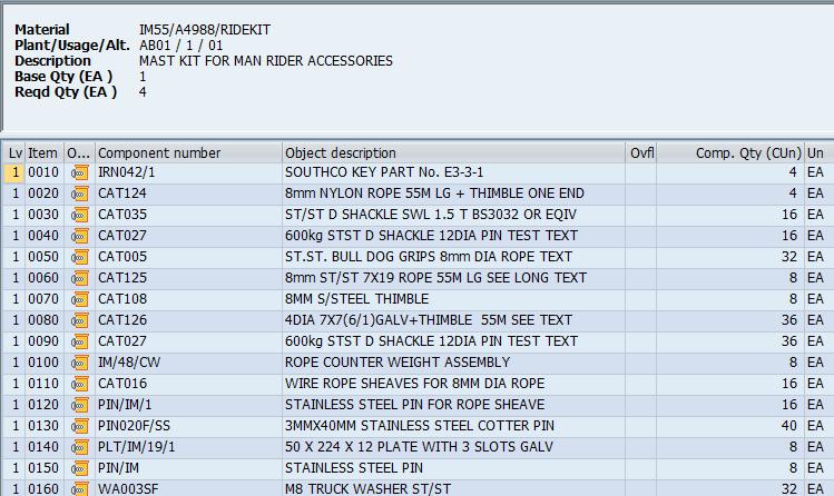
6.2 WIRING INFORMATION CHART
Statement: This document certifies that all materials and processes used on the products listed above, comply with the specifications and drawings supplied, within our BS EN ISO 9001:2015 Certification. To meet the
Project O&M Manual
2.1 Certificate Of Conformity Continued:
Statement: This document certifies that all materials and processes used on the products listed above, comply with the specifications and drawings supplied, within our BS EN ISO 9001:2015 Certification. To meet the
Project O&M Manual For Mechanical Operation and Maintenance
5.0 Appendix - Material Test Certifications, Data Sheets, and Manuals:
Appendix Information:
The following information pertains specifically to this project and includes examples of specified products, technical data sheets, engineered drawings, certifications, and product installation and maintenance manuals.
MAST ASSEMBLY AND INSTALLATION
MAST TYPE: INTACC & EXTACC MAST
WE STRONGLY RECOMMEND THAT THESE INSTRUCTIONS ARE READ CAREFULLY BEFORE ATTEMPTING TO INSTALL AND OPERATE THIS EQUIPMENT.
THE INSTRUCTIONS THAT FOLLOW ARE FOR THE ASSEMBLY AND INSTALLATION OF A MAST WITH HEADFRAME AND PLATFORM ATTACHED PRIOR TO ERECTION.
GENERAL
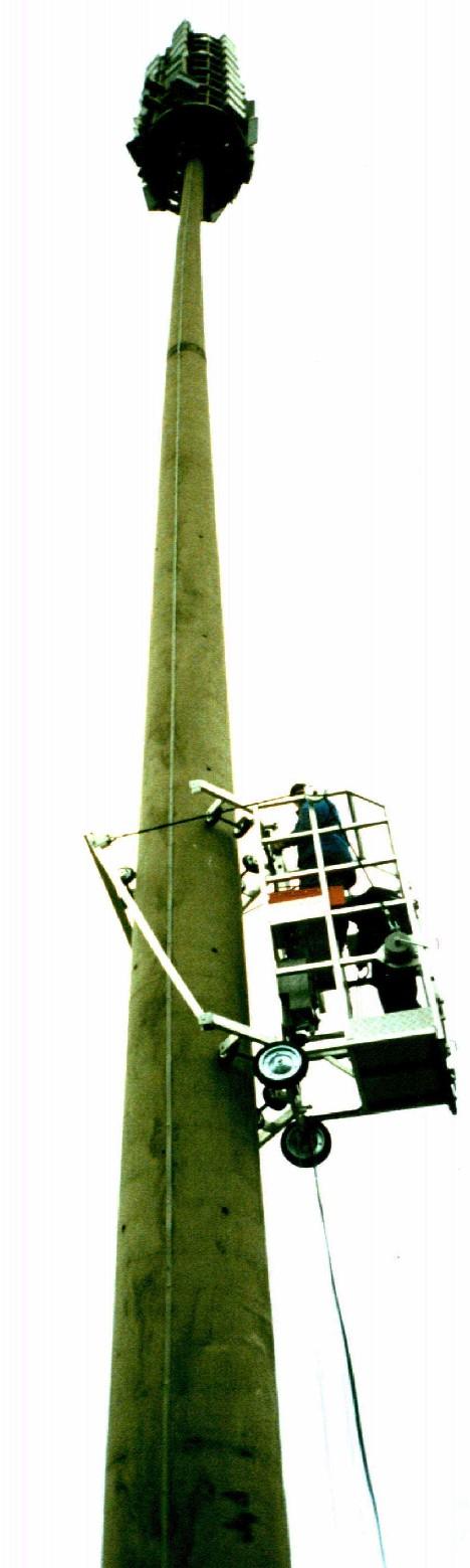
These masts are used for Stadium Lighting applications with mast heights up to 50m. The headframe typically consists of an access platform positioned at the lower Luminaire level. Climbing ladders are provided to give access from the platform to the higher levels although additional platforms are sometimes used.
Access from ground level to the headframe can be achieved by means of an external or internal ladder. All access ladders are fitted with a Fall Arrest system to safeguard personnel. Headframe access for Extacc masts can also be via an external lift, which can also be combined with the internal ladder system on the same mast if required.
Each mast is supplied in kit form for on site assembly. The foundation bolts should be cast in concrete 3 to 4 weeks prior to erection of the mast to allow time to cure. Foundation block sizes for a variety of ground conditions can be supplied on request.
Masts are constructed from steel to EN10025 grade S275 or S355, pressed to form a tapering polygonal shaft each up to 15m in length. (For export orders lengths are limited to 12m) The shafts are slotted together to form the mast and require no on site welding or bolting. The masts and foundation bolts are finished galvanised with small fasteners from stainless steel. One or two rings of bolts attach the mast to its foundation. Flanges are also used to connect the headframe assembly to the top of the mast.
Electrical cables are catered for by providing horizontal rails for trunking, ties or cleats on Intacc masts, with a series of catenary wires being provided for Extacc masts.
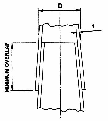
Because these masts are designed for specific applications it is essential that reference is made to the engineering drawings during assembly. The drawings will give details of design overlaps although these will obviously vary due to manufacturing tolerances. The minimum permissible shaft overlaps can be determined from Fig. 1.
For t<= 5mm
Minimum Overlap = 1.94*D
For t>= 6mm
Minimum Overlap = 1.73*D
Where D = A/F’s of outer shaft at the top of the Design Overlap
Fig. 1 Minimum Overlaps for Shafts
EQUIPMENT REQUIRED. (Not Abacus supply)
i) 2 no. 7 tonne Tirfor c/w 50m wire rope.
ii) Various wire ropes, soft slings and shackles
iii) 4 No. 30mm ‘D’ shackles
iv) Supply of liquid soap
v) Steel beam 2m long with attachment points for ‘D’ shackles along its length
vi) Supply of timber supports and packing
vii) 14Ib Hammer and hard wood packer
viii) Mobile crane specification to be advised by Abacus Lighting or local specialists
ix) Torque multiplier and wrench
MAST ASSEMBLY
Reference should be made to the illustrations
For export orders the masts will be containerised. If the smaller shafts are fitted inside larger ones, they will need to be carefully unpacked on site to avoid damaging the galvanised finish.
It is intended that the shafts and headframe are assembled together prior to the mast being erected onto its foundation.
The shafts should be laid out on open ground to facilitate correct identification and their ends examined for signs of damage. The orientation of the seam welds relative to each other is not important.
Base sections with circular flanges should be supported on timbers and chocked to prevent rolling. Mark the base with both design and minimum overlaps as determined in Fig. 1. Pack the upper end of the base section so that it is clear of the ground. Position packers at least 1.5m from the open end to allow plenty of room for the next shaft to overlap. Check the overlap area for any damage, excess zinc or weld, which may impede fitting of the shafts together and rectify if necessary.
Smear liquid soap over the outside of the base for the length of the overlap and carefully slide the shaft into position. Any mountings for ladders or cables must be in alignment. Ensure the flats do not rotate relative to each other since a shaft wedged with a corner to a flat will be very difficult to separate. See Fig. 2.
(Typically 18 sided, 8 sides shown for clarity)
Fig. 2 Shaft Orientation
MAST ASSEMBLY
Referring to Fig. 3, attach 2 Tirfors between the flange and steel beam as illustrated. The steel beam must have timber packing placed between it and the edges of the shaft to prevent deformation. With the shaft supported by a crane, lift and feed it onto the end of the base. It is essential that the Tirfors are operated simultaneously when pulling the shaft into position. Agitate the shaft up and down to aid bedding of the shaft into position. Striking the beam across the ends of the shaft with a sledgehammer will also ease the assembly.
As sliding takes place periodically sight down the assembly to check for straightness. Do not stop pulling if the minimum overlap is reached. It is important that the shafts are as tight as possible as they may settle on erection and any suspension wire lengths will need to be readjusted. Remove the steel bar in readiness for pulling the next shaft into position. Remove any surplus soap from the base section.
Repeat the procedure for all remaining shafts. If internal or external ladders are provided these should be fitted, as should the fall arrest system in accordance with the manufacturer’s instructions.
Fig. 3 Shaft Assembly
A = Design Overlap
B = Minimum Overlap
MAST ASSEMBLY
The ladder attached to the upper shaft is rigidly mounted, with all others being secured by a clamp. These sliding clamps should be left loose until the mast shaft has been erected to allow for any settlement. Fit the fall arrest system to the ladder in accordance with the manufacturer’s instructions.
If the headframe access is by an external lift it will be necessary to install the lift and safety cables. Referring to Fig. 4 thread each wire through the pulleys at the top of the mast and then down the inside of the mast. Fit the anchor pin to the anchor plate and secure the wires using thimbles and bulldog grips as shown. At this stage only lightly tighten the grips, as the final adjustment will be made when the mast is erected. Fit the ballast weights to the end of each wire.
Assemble the headframe platform including beams, floorplates and handrailing as per engineering drawings. The completed assembly should then be attached to the flange on the top shaft. Ensure when attaching the platform to the shaft that the removable rear handrail is uppermost.
Assemble the headframe with the door aperture uppermost. Fit all cross arms and ladders as shown on the engineering drawings. Install the fall arrest system to the ladders. It is recommended that the fitting and wiring of luminaires is carried out whilst the headframe is at ground level. The electric cable from each luminaire should be threaded along the cross arm and through the glands in the shaft wall. Then down the headframe tube and out through the door aperture. Sufficient cable to reach the power distribution board at ground level must be temporarily coiled on the headframe. Tie each bundle of cables to their respective cross arm mounting on the headframe tube.
Apply sealant to the headframe tube blanking plate and bolt to the headframe tube. Fit the lightning arrester spike and obstruction lights if provided.
1.Ballast Weights
2.‘D’ Shackles
3.Pre made Rope Termination
4.Bulldog grips
5.Loose Thimble for Site Termination of Rope
6.Anchor Bar
7.Anchor Pin
8.Retaining Pin
9.Anchor Plates Welded to Inside of Mast
10.8mm Dia. Lift Cable
11.8mm Dia. Safety Cable
Fig. 4 Lift and Safety Cable Layout
MAST INSTALLATION
Prior to lifting the headframe into place, its orientation relative to the final position of the mast should be considered. It is recommended that a corresponding hole in both the headframe and platform flange is clearly marked to facilitate alignment. Lift the headframe into position as shown in Fig. 5. Ensure that mastic sealant has been applied to the flanges and that the marked holes align correctly. Fit the fixing bolts and tighten to the specified torque setting.
Remove the electric cables from their temporary stowed position on the headframe and carefully thread down the inside of the mast. For INTACC masts horizontal rails are provided for securing electric cables at approximately 3m centres. Electric cables in EXTACC masts are usually secured to a catenary wire in bundles of 7 which in turn is secured to either a suspension wire support plate or clamp plate welded inside the headframe tube. See Fig. 7 for details. On masts with external lifts it will be necessary to position the electrical cables away from the internal lift wires.
opening position.
Use timber packing when using wire slings to protect galvanised finish.
Adjust length of slings such that the headframe flange and platform flange are vertically aligned.
Fig. 5 Lifting Arrangement for Headframe Assembly
Prior to lifting the mast its orientation relative to the foundation bolts must be considered. It is recommended that a holding down bolt and its corresponding flange hole be clearly marked to facilitate alignment.
To facilitate erection of the mast, lifting lugs are provided at points on the flange and top shaft. A lifting sling should be attached to the lugs positioned either side of the mast at flange level. These slings should be connected to a third sling or rope of sufficient length to pass through and out of the lifting lugs located on the top shaft. This arrangement will provide a lifting point for the mast and additionally, prevent the shafts from separating during the lifting operation. Erectors must ensure that the ropes and slings used during erection of the mast are of sufficient capacity to support the weight of mast during lifting.
If external ladders are fitted ensure the slings are positioned so that the ladder will not be damaged during the lift. It should be noted that the platform is fitted with a removable rear handrail to provide clearance for the lifting slings during erection. Each holding down bolt is each fitted with two nuts and washers, the upper nut and washer should be removed. The threads should be examined for any damage and rectified using a Die Nut if necessary. The lower nuts should be set in level plane using a steel bar and spirit level across each opposing pair of nuts.
Door
MAST INSTALLATION
Referring to Fig. 6 lift the mast, align the previously marked bolt and hole, and carefully lower the mast onto the foundation bolts. Secure the mast with the upper set of retaining nuts and washers. Remove the lifting slings and tie wires.
Enlarged detail at top of mast showing route of slings through gussets.
2 No. Support Slings
6 Lifting Arrangement for Mast Assembly
Check the monopole for vertical alignment, noting the shaft taper, which will be given on the engineering drawings. The vertical alignment can be adjusted using the upper and lower nuts as necessary. Once the alignment is satisfactory all bolts should be tightened to the specified torque setting.
If the gap below the flange is to be grouted it is essential that adequate provision is made for ventilation and drainage of any water collecting inside the mast.
With the mast installed ensure that any internal or external fittings such as ladders, cable guides etc. are secured. Re-connect the rear platform handrail and secure in position.
Where fitted, check the internal lifting and safety wires for tension. With the lower end still secured to the anchor bracket pull the wire to move the ballast weight at the top of the mast. There should be about 50mm of free movement in the wire. Adjust as necessary before finally tightening the bulldog grips. (Please note that the bulldog grips should be re-tightened when the wires have been preloaded as detailed in the operating instructions)
Installers should be aware that if they chose to deviate from the suggested installation method described in the previous sections, then it is their responsibility to produce a method statement which will ensure that the mast is installed in a safe manner.
Fig.
Main Lifting Sling
Anchor Gussets
FOUNDATION BOLTS – TORQUE SETTINGS
Fig. 7 Typical Cable Suspension Details
Mast shown is not indicative of any one type. Detail is typical only.
18 No. Foundation bolts. Arrangement is typical although other combinations of foundation bolts do occur.
FOR FURTHER ADVICE CONTACT THE ABACUS TECHNICAL DEPARTMENT
Fig. 8 Typical Mast Foundation Bolt Arrangement
Levelling nuts under flange
Spacer plate
Cable duct Foundation
Door opening
MAST OPERATING INSTRUCTIONS
MAST TYPE: INTACC & EXTACC MAST
WE STRONGLY RECOMMEND THAT THESE INSTRUCTIONS ARE READ CAREFULLY BEFORE ATTEMPTING TO OPERATE THIS EQUIPMENT.
REFERENCE SHOULD ALSO BE MADE TO THE EXTERNAL POWERED LIFT MANUFACTURERS OPERATING AND MAINTENANCE INSTRUCTIONS BEFORE USE.
LADDER ACCESS
For Extacc and Intacc masts using ladders a Railok Fall arrest system is employed. This comprises of an aluminium rail bolted to the ladder rungs. The operative is provided with a safety harness and Railok ‘truck’ which is attached to the rail prior to climbing the mast. The truck is detached from the rail when the climb is completed and re attached prior to descent.
EXTERNAL POWERED LIFT
Where an external lift is provided this must be attached in the first instance to the lift and safety wires stowed inside the mast.
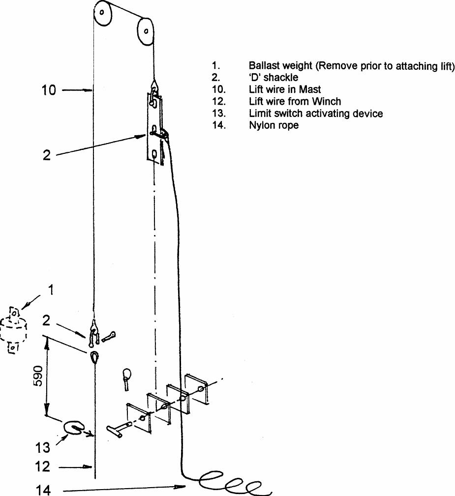
Refer to the manufacturers operating instructions when fitting the suspension wires to the lift. Position the lift below the ballast weights suspended at the mast head and secure the lift clamp frame around the mast. Tighten the frame against the mast as detailed in the manufacturers instructions using the 2 winches and elasticated cables provided for this purpose. Fit the extension ladder to the top of the lift frame. The ladder in the lift and the extension frame should be in line with each other. Attach approximately 45m of nylon rope to one of the steel wires stowed inside the mast, which corresponds to the safety wire on the lift. Release the anchor pin and lower until the ballast weight is in line with the top of the lift. Detach the ballast weight and attach the wire to the safety wire on the lift. Pull the nylon rope and haul the lift safety wire to the top of the mast. Attach the safety wire to its anchorage inside the mast. Fit the nylon rope to the remaining wire in the mast and lower the ballast weight to the top of the lift. Detach the ballast weight and attach the wire to the winch lift wire. Fit the limit switch activating disc, to the winch lift wire 590mm from the thimble bearing face. See Fig. 1 for details. Haul the lift wire to the top of the mast and secure to the anchorage inside the mast.
Refer to the lift operating instructions and thread both safety and lift wires through the winch mechanism.
If the wires in the mast are being used for the first time load the lift with ballast to its working capacity and operate the lift to raise it about 0.5m off the ground. Check the safety mechanism function such that both winch and safety wire have been subject to their working load. Lower the lift to ground level and re tighten the Bulldog grips at the wire rope connections inside the mast base, to compensate for any settlement of the wire strands which may have occurred as a result of loading.
Refer to the Lift Manufacturers instructions for operation of the unit.
EXTERNAL POWERED LIFT
Removal of the lift from the mast is the reversal of fitting.
ENSURE THAT THE BALLAST WEIGHTS ARE ATTACHED TO THE WINCH AND SAFETY WIRES BEFORE PULLING THEM UP THE MAST HEAD FOR STOWAGE PURPOSES.
MAST ROUTINE MAINTENANCE
MAST TYPE: INTACC & EXTACC MAST
WE STRONGLY RECOMMEND THAT THESE INSTRUCTIONS ARE READ CAREFULLY BEFORE ATTEMPTING ANY MAINTENANCE ON THIS EQUIPMENT.
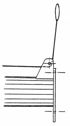
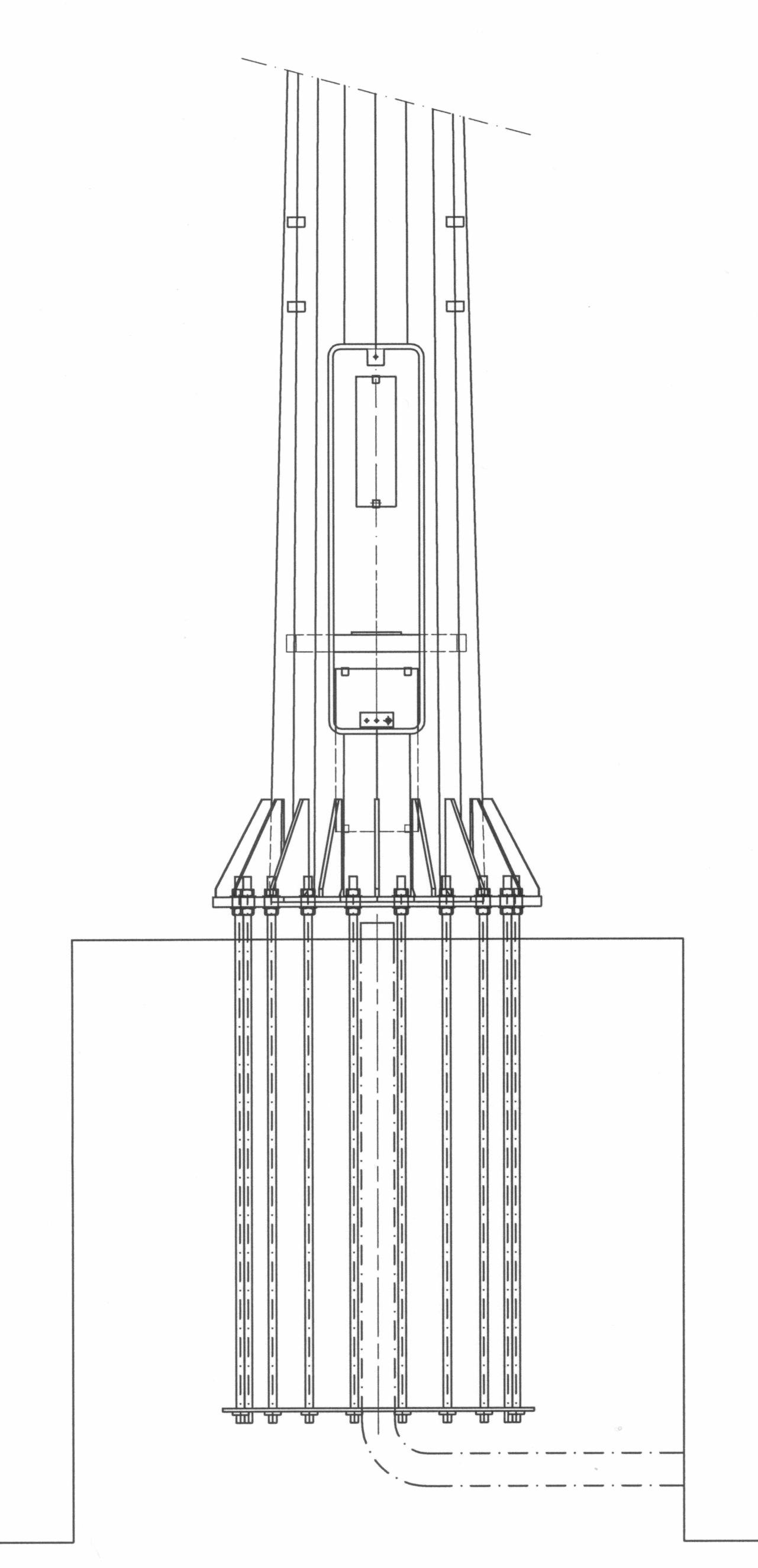
The masts are of hot dipped galvanised steel construction with tapering slip joint type multisided shafts. The illustration opposite is a typical arrangement of the mast types. Maintenance requirements are minimal but the following checks are recommended at the intervals stated.
Reference should be made, where appropriate, to the manufacturers maintenance instructions for the ladder Fall Arrest System and External Power Lift.
EVERY TIME THE MAST IS CLIMBED
1. Check that the ladder fall arrest system components are present and working correctly.
2. Ensure the safety harness is complete and undamaged.
3. Check that the external lift functions correctly and that its components are undamaged.
EVERY 12 MONTHS
1. Carryout safety inspections of the climbing devices as recommended in the manufacturers instructions.
2. Check that the door cover is secure and that the locking screw functions satisfactorily. Lightly grease the screw threads.
3. Check that the foundation bolts have not worked loose. The torque settings for Grade 8.8 bolts are as follows:
M20 = 250Nm
M24 = 425Nm
M30 = 850Nm
M36 = 1450Nm
M42 = 2350Nm
M48 = 3500Nm
AS REQUIRED
1. Paint the shafts and headframe. Aesthetically the galvanised finish will typically last 5 - 7 years before painting is required. In polluted or saline environments this may be shorter and in mild climates considerably longer.
EXTERNAL ACCESS BY POWERED LIFT OR LADDER WITH FALL ARREST.
INTERNAL ACCESS BY LADDER WITH FALL ARREST.
TYPICAL ARRANGEMENT OF MAST
MAN RIDER
MAN RIDER
3) INSTALLATION
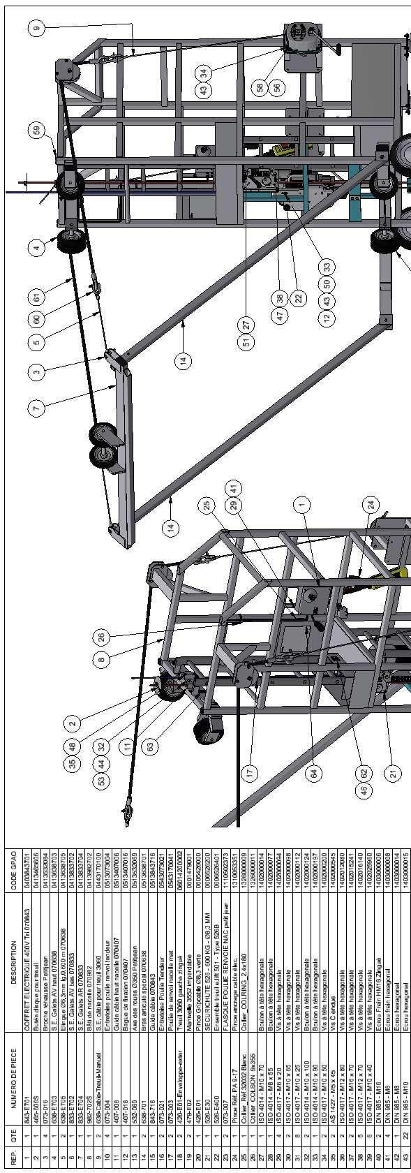
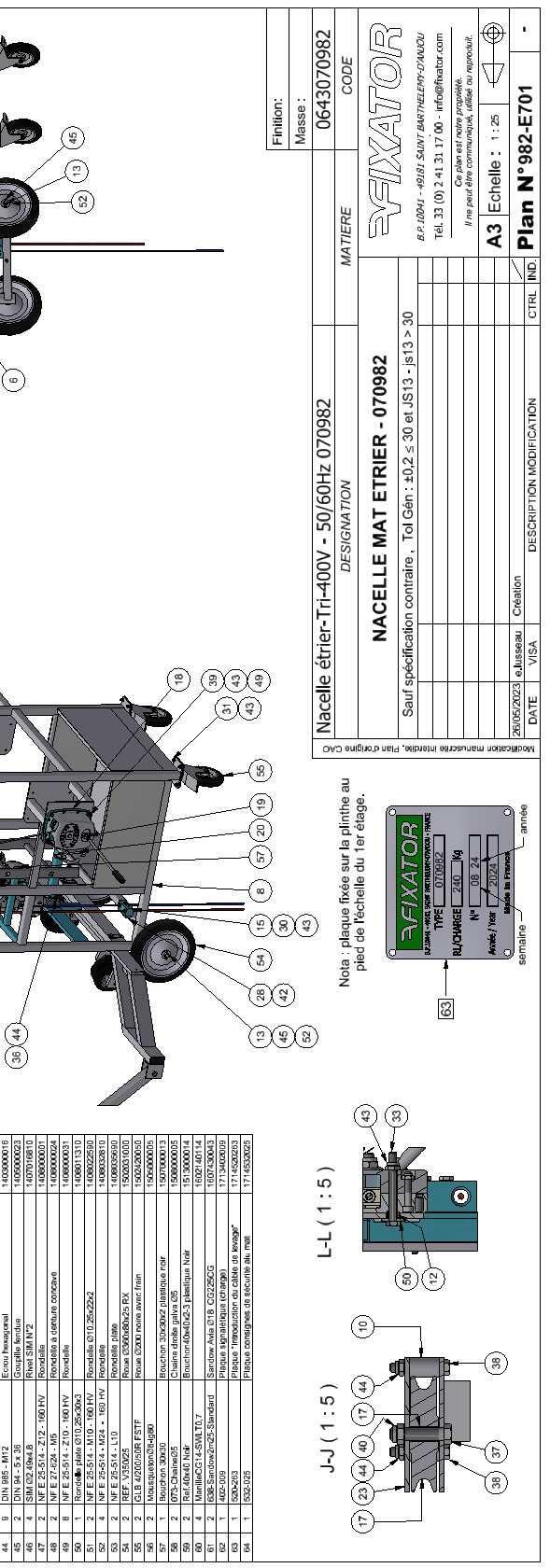
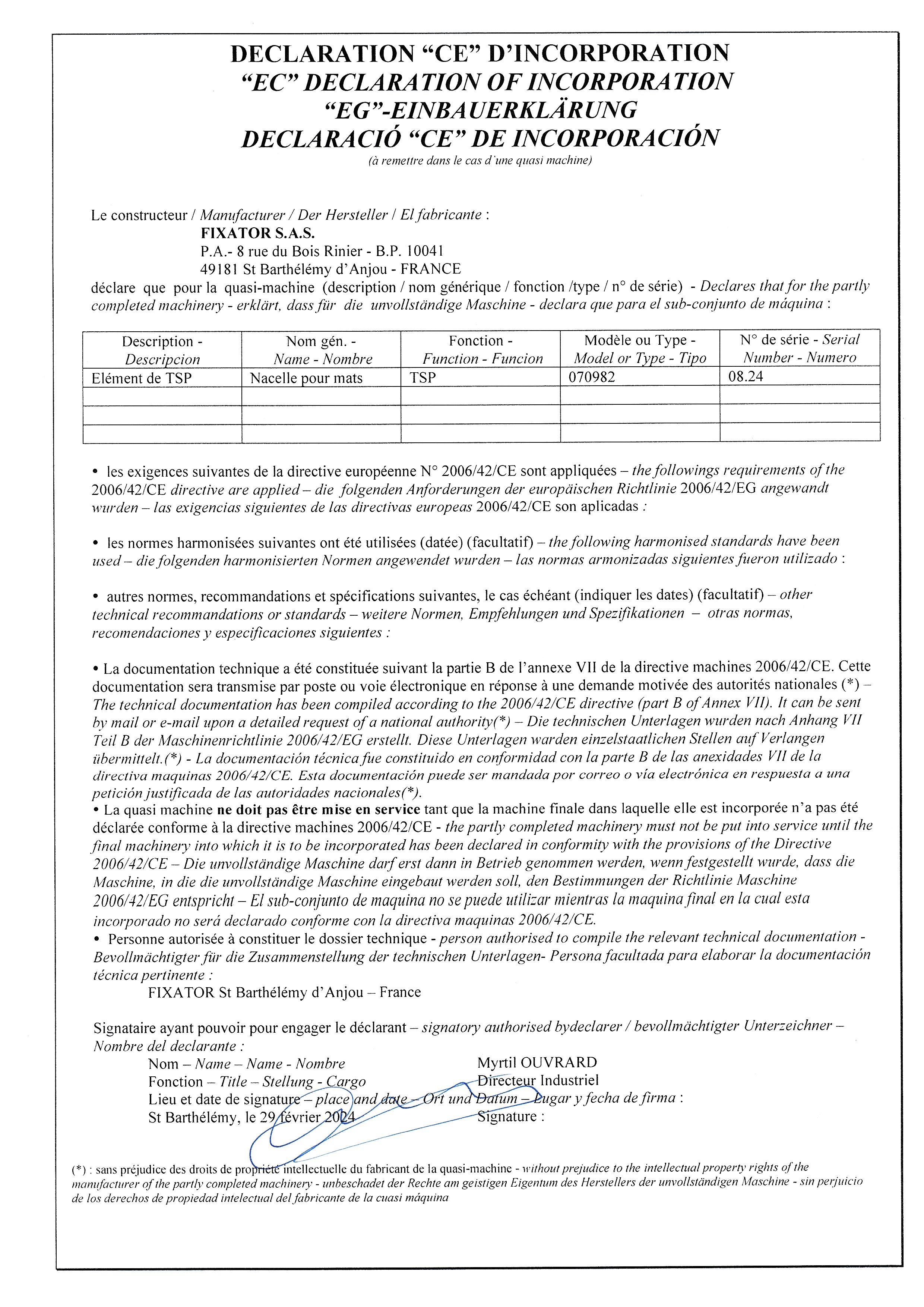
MAN RIDER
Ref: 070982
Page: 4/17 01/24
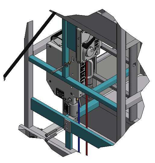
a) Installation of the winch on the cradle with :
• 2 Screws HM12 x 80 + nuts self-locking.
• 1 Screw HM10 x 90.
• 1 Washer Ø10,25 x 30 x 3.
• 1 Guide bushing Ø16 x 2.
b) Introduce the working wire rope:
- In the guide-cable high.
- Then in the winch.
- Then in the guide-cable low.
c) Introduce the safety wire rope inside the guide-cable high, then in the winch and in the guide-cable low.
d) The top travel end abutment is fixed on the lifting wire rope.
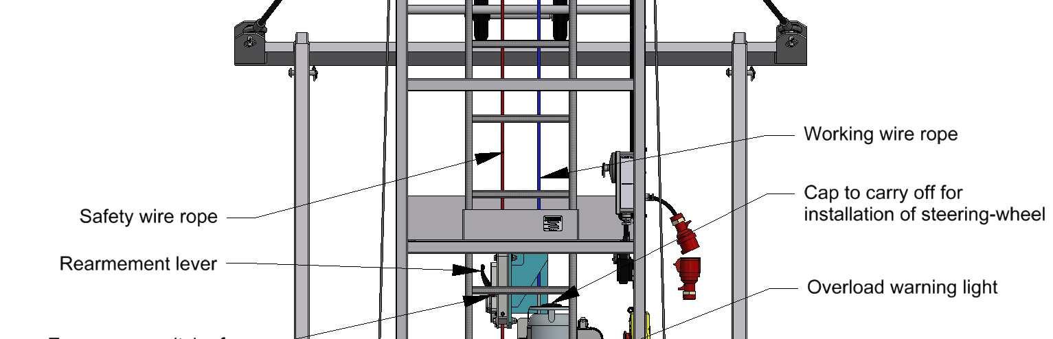
Working wire rope
Safety wire rope
Working wire rope
MAN RIDER
Ref: 070982
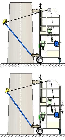
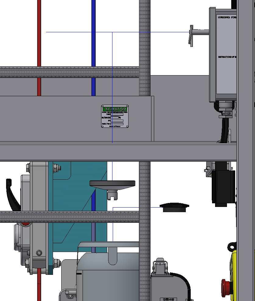
Page: 5/17 01/24 4) ADJUSTMENT OF THE 2 elastic bands
a) Before the cradle’s installation, elastic bands must be slack, at maximum capacity.
b) In advance of lifting operation, the elastic bands must be tensed so that their ends get at 10 cm from the manual winch. Then place safety snap-hooks on wire ropes.
c) Back to on ground, slack entirely the 2 elastic bands, before disassembling the back guide-pulley.
RECOMMENDATIONS
CAUTION: if you let the cradle in work position on mast, NEVER LET TENSED THE ELASTIC BANDS
MAN RIDER
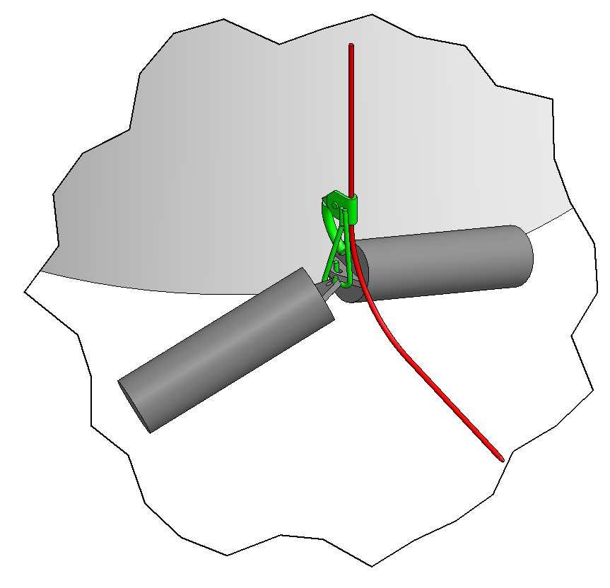
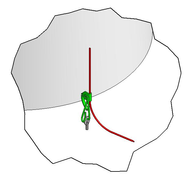
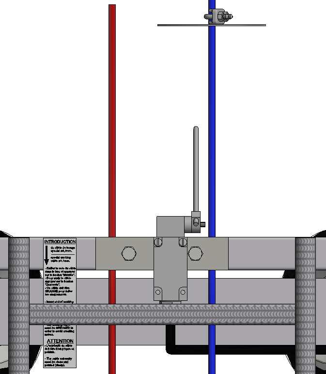
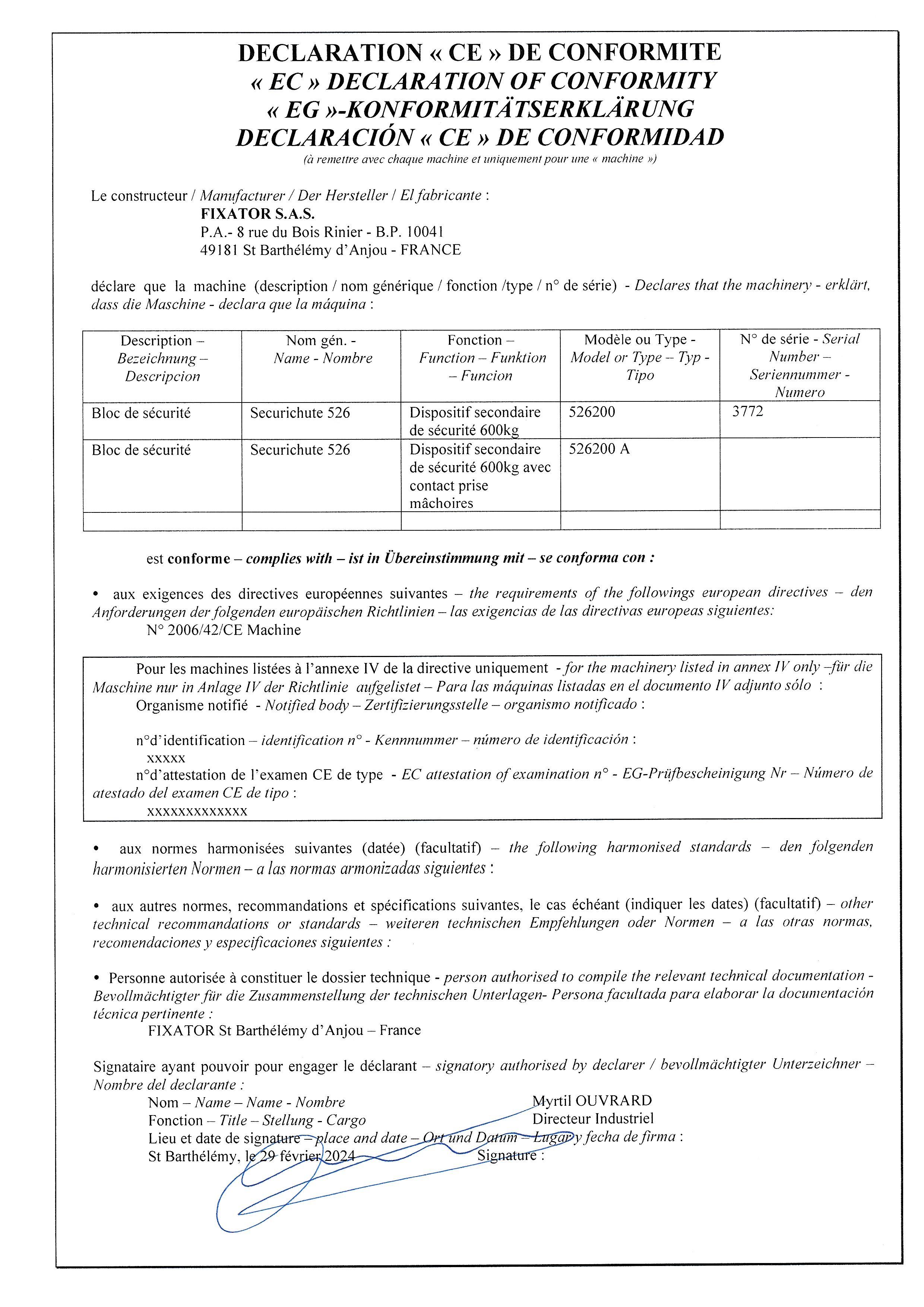
5) TENSIONING THE SAFETY WIRE ROPE
Ref: 070982
Page: 6/17 01/24
When using the cradle, the safety wire rope must be kept tight to ensure the smooth working of the fall-arrest system. Aiming at this, you need to a counterweight at the end of the safety wire rope or secure the safety wire rope on the ground. Safety wire rope
MAN RIDER
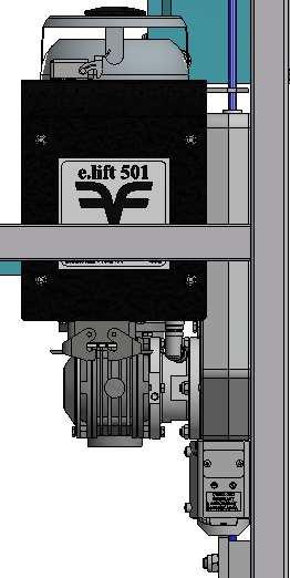
6) e.lift 501 WINCH SPECIFICATIONS
Winch with automatic wire rope travel for unlimited working heights.
Adherence is guaranteed by jamming with pressure roller.
• Anti-falling jaws grip on safety wire rope by over speed.
• 1 manual release (emergency switch) for anti-falling jaws.
• 1 emergency descent (no power) by action on the brake lever (under controlled speed).
STEEL WIRE ROPE Ø8,3 mm, Construction 5 x 26 with polypropylene core Breaking 5200 Kg.
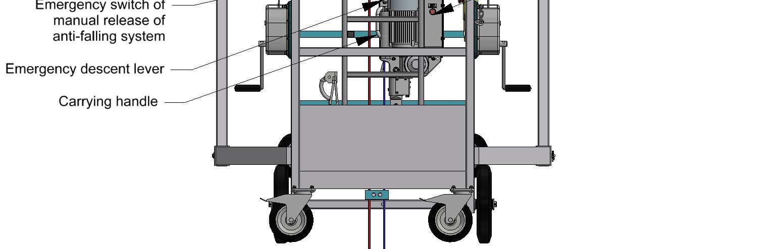
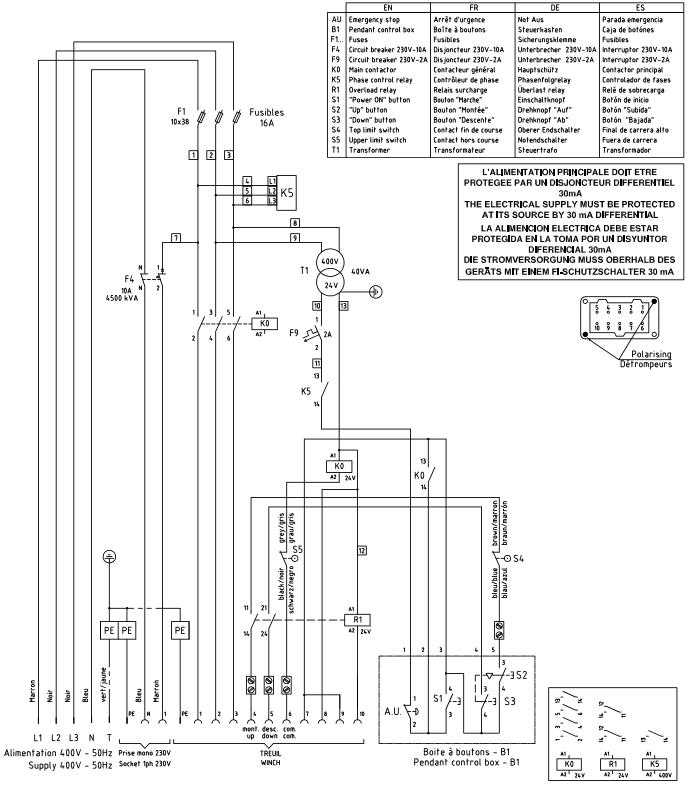
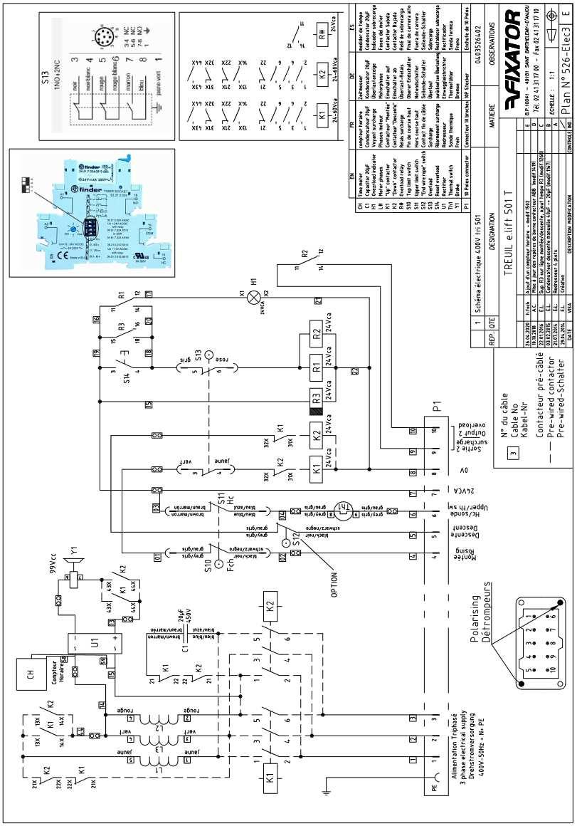
7) CONTROL BOX
MAN RIDER
Ref: 070982
Page: 8/17 01/24
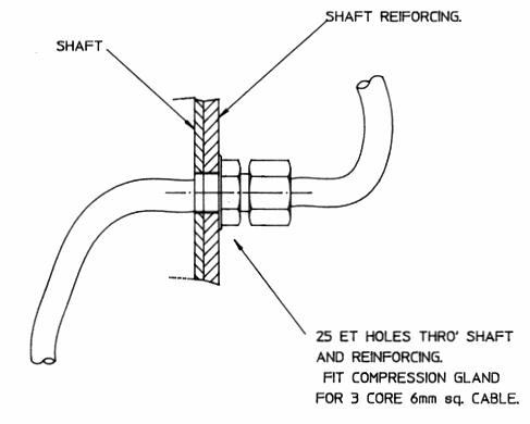
Connect central control box to power supply after making sure that supply voltage corresponds to hoist motor voltage and that power source is duly protected by a 30 mA differential circuit breaker.
Connection by means of a 16 Amp socket.
a) Single phase WINCH:
Power cable 3 x 4 mm² - type HO 7 RNF
2 phase-lead + earth For big lengths, please contact us.
b) Three phase WINCH:
Power cable 5 x 2,5 mm² - type HO 7 RNF
• For three phase motor only : After pressing « UP », if no movement, invert the two phase leads inside the red power supply plug of the control box.
NOTE: After implementation of cradle, you have to operate starting-up tests before use.
8) PRELIMINARY TESTING
MAN RIDER
a) CHECK THAT the centrifugal blocking jaw mechanism operates properly. To do this, pull the safety wire rope up manually. This should cause the blocking jaw mechanism to trip. Reset the mechanism with the reset lever.
b) RAISE the man rider. While bringing it down again, trip the blocking jaws manually. This should cause the descent of the man rider to stop.
Move the emergency descent lever upwards to make sure that the safety wire rope is firmly clamped between the jaws. To reset the system, move lever upwards by 10 cm and pull reset lever down.
c) EMERGENCY DESCENT
Raise man rider by about 1 meter. Disconnect power supply and push emergency descent lever upwards. The man rider will come down at controlled speed. If descent proves difficult in the case of a new hoist (or in the absence of load) use the control wheel at the end of the hoist motor shaft.
DISMANTLING:
1. Withdraw counterweights.
2. Withdraw the working wire rope.
3. The safety wire rope is going out manually.
4. Press and turn the emergency switch of the anti-falling release.
5. Draw on the safety wire rope while maintaining the anti-falling system rearmament lever.
Ref: 070982
Page: 9/17 01/24
9) OVERLOAD DETECTOR
MAN RIDER
The overload sensors (integrated into the winch) protect the man rider in the following situations:
a) overload
b) contact of the rising platform with a part of the overhang of the building.
A red control light on the control box signals this type of overload.
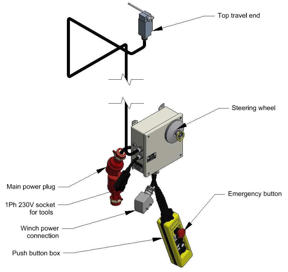
10)UPPER LIMIT SWITCH
The ascent of the man rider is interrupted when one of the upper limit switch touches the disk or the tilting plate attached to the wire ropes.
The lowering process is still possible.
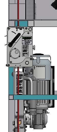
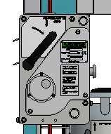
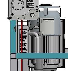
11) EMERGENCY LOWERING
The electrical winches are equipped with a manual emergency descent system in case of electrical power cut.
a) Cut the electrical power supply by disconnecting the plug.
b) Lift the emergency lowering lever (without forcing) which is situated at the rear of the winch, so as to open the service brake. The man rider descends on its own and its speed is automatically limited and controlled.
c) In case the man rider should not descend on its own, an initial impulse has to be given by releasing the manoeuvring wheel (1) situated on the driving shaft after having removed the plastic cap of the shell (2).
d) The man rider stops moving as soon as the brake lever is released.
e) Once the man rider is on the ground, remove the manoeuvring wheel and put it back onto the control box. Put the plastic cover back to the top of the engine.
Ref: 070982 Page: 10/17 01/24
12) USING THE MAN RIDER
MAN RIDER
Ref: 070982
Page: 11/17 01/24
a) It is imperative to use only wire rope specified by FIXATOR®. These have to be replaced when one of the defects have been detected.
b) Check the correct functioning of the winches, brakes, the “Sécurichute” safety device, extra or upper limit switches, overloads, emergency stop…
c) Take particular care in checking the attachments and the fixings of the working and safety wire ropes.
d) Verify that the loads on the man rider do not exceed the admissible weight and that there is no accumulation of snow, ice, waste or excess of materiel on the man rider.
e) If stipulated by the work site regulations, operators must wear a safety helmet.
f) It is recommended to mark the danger zone on the ground, as tools or other material used on the man rider may fall in that area. These recommendations become binding if the public can access the affected area.
g) The equipment is meant to be used in well-lighted areas, whether naturally or artificially. In case of artificial lighting, the operator must have sufficient light at his disposal.
h) Verify that no overhanging objects on the façade of the building could collide with the man rider.
i) Verify that the ambient temperature is between - 10°C and +55°C
j) Never work on the man rider in difficult weather conditions (violent winds above 50km/h or thunderstorms).
k) Upon completion of the work, the site manager has to bring the man rider into the out-of-service position and disconnect the electric power supply to avoid any unauthorised or abusive use of the equipment.
l) No one in the man rider if they move to the ground.
It is prohibited to:
a) Use the man rider without the safety wire ropes and without the Sécurichute safety device.
b) Unplug the security provisions (overload, upper limit switch…)
c) Overload the man rider.
d) Move loads above the personnel.
13) MAINTENANCE
Important revision
MAN RIDER
The winch and safety device must be serviced every year.
Ref: 070982
Page: 12/17 01/24
The results of the general periodical tests have to be listed in the security register opened by the company manager in compliance with the regulations currently in force.
Preventive maintenance
Check:
Every day:
The proper operation of safety devices (Emergency stop, Top Limit Switch, Ultimate Limit Switch, Fallprevention)
The good overall condition (visual) (wire ropes, platform, pins, hoist, …)
These everyday operations can be carried out by a user; refer to Manual ref 1813000133.
Every week:
The proper operation of the emergency brake
The proper operation of the tilt control and the automatic level reset
The proper operation of the overload
Every year or every 200h:
Check the grooved pulley.
Check the bearings (spreader, ring gears, etc.)
Check the motor brake.
Check every safety device at rated load.
Clean and grease the gears (eg grease KLUBERSYNTH AG14-61 or BYMO EP)
These operations must be carried out by a competent person, trained by FIXATOR or its dealers. The manual FIX022 details these periodical operations or controls. A load test must be carried out after every operation.
Lubricating the wire ropes
The working wire rope must be regularly greased or lubricated with Teflon. Use the following materials for the lubrication:
• Grease IGOL SHP 50
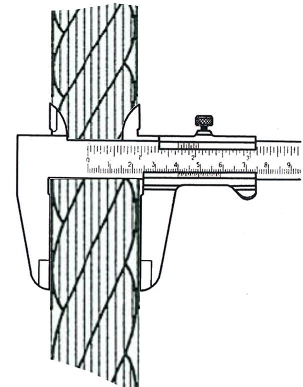
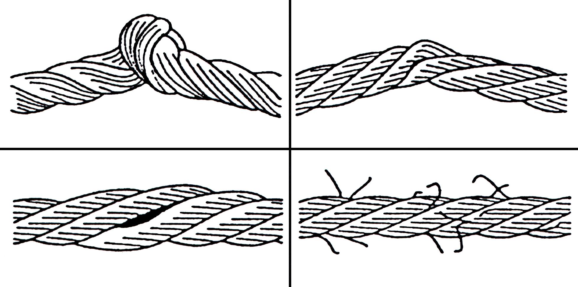
Replacing wire ropes
Only wire ropes recommended by FIXATOR® will assure a safe functioning of the winches.
Wire-rope minimum diameter Ø 7.4 mm (For Ø 8,3 mm rope)
The wire ropes have to be replaced in the following cases:
• More than 10 wires torn over a length of 25 cm for the Ø8.3 mm wire rope.
• Deformations of the catch pan or tearing of one of the rope strands.
• Crushed rope, unstranding.
• Strong oxidation.
14) TROUBLE - SHOOTING
MAN RIDER
HOIST RESPONDS TO “UP” BUT NOT TO “DOWN”
CHECK THAT:
Ref: 070982
Page: 13/17 01/24
• Mechanism of blocking jaws is operational.
• Wire rope slack protection is in working condition.
HOIST RESPONDS TO “DOWN” BUT NOT TO “UP”
CHECK THAT:
• Top limit switch is operational.
• Permanent capacitor is in good condition.
• Starting capacitor is operational.
HOIST DOES NOT RESPOND
CHECK:
• Thermal protection of the motor.
• Capacitors.
• Tripping of main switch.
• Presence of overload.
TO ENSURE PROPER HOIST OPERATION
• Before starting to operate the hoist, CHECK THAT the working wire rope is free from dents, broken strands, kinks, etc.
• IF you hear creaking noises when going “UP”, lubricate the working wire rope.
• Proper hoist operating can only be ensured and guaranteed if the wire ropes that are used are conforming to the Manufacturer’s original specifications.
MAN RIDER
Ref: 070982
Page: 14/17 01/24
MAN RIDER
Ref: 070982
Page: 15/17 01/24
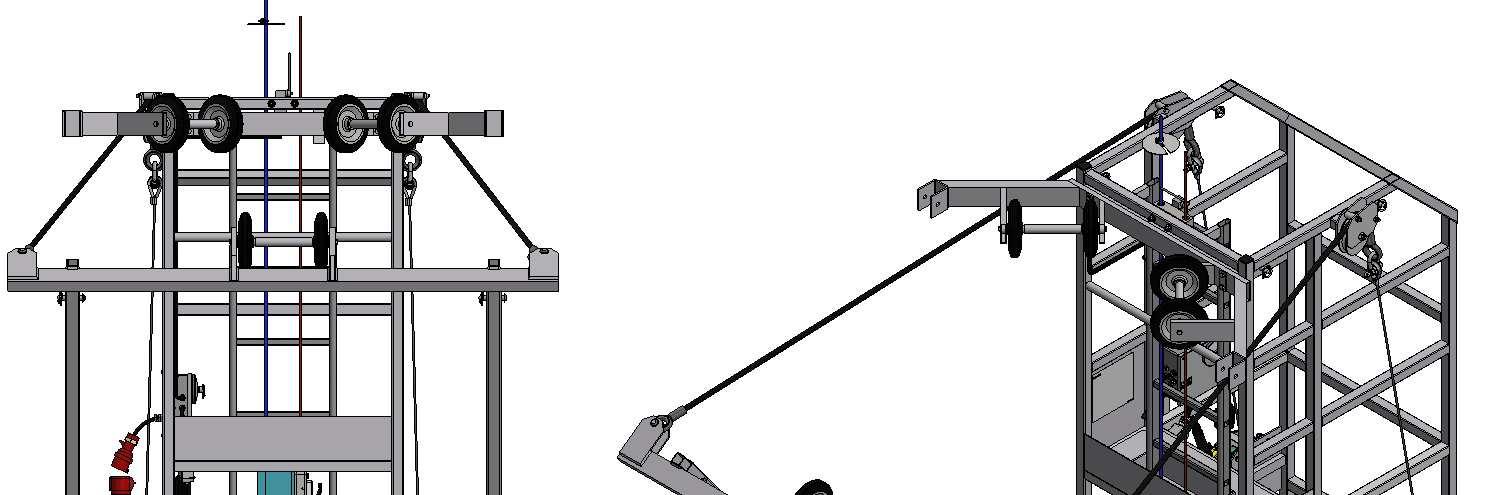
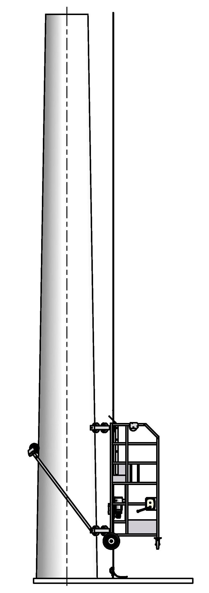
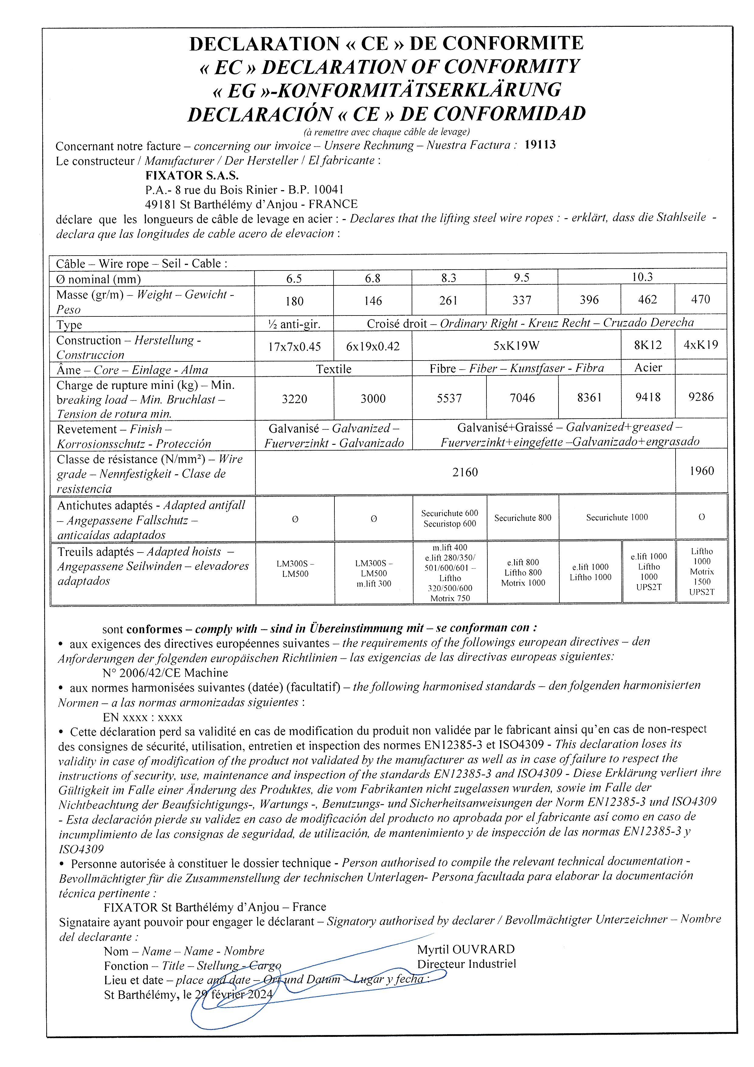
Installation Instructions:
MAN RIDER
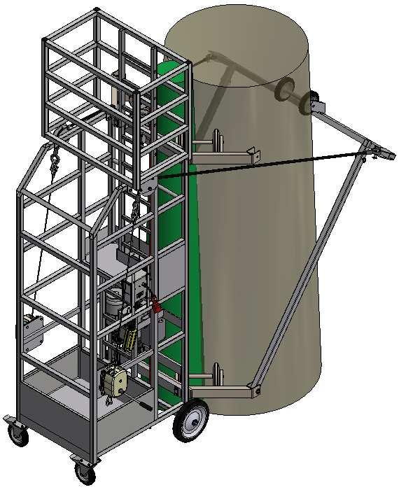
• The installation of the man rider requires the presence of two people.
• Move the man rider equipped with upper extension at the foot of the mast.
• Connect the electrical box (see § 7).
• Installation of safety and working wire ropes and insertion into the hoist + safety device (see § 3).
Ref: 070982
Page: 16/17 01/24
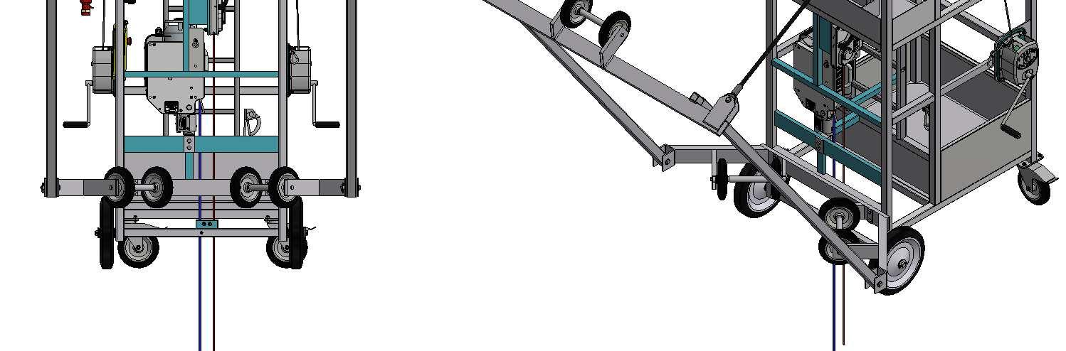
• Operate the hoist (up button) in order to tilt the man rider and rotate it against the mast.
• Adjust the 2 elastic bands (see § 4).
• Proceed to the preliminary tests (see § 8).
BE CAREFUL: one person should help engaging the man-rider onto the guiding rail, from the ground, for at least 1,20m.
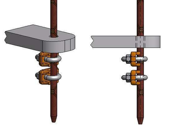
• The safety wire rope is attached to the bottom of the mast and tensed (see § 5).
• The working wire rope is only secured at the foot of the mast to prevent it wrapping around the mast. Example:
Working wire rope
Additional maintenance:
• Check the proper rotation of the guide rollers.
• Check the setting of 3 guide points by HM10x70 screws + brake nuts.
MAN RIDER
Page: 17/17 01/24
Latchways® Vertical lifelines
Technical Datasheet: Installation
MSA Latchways Towers Climbing Rail System
Top Anchor Assembly 35509-00
Coil Shock Absorber 85536-00
Swage Slip Indicator 85025-00
Wireguide Assembly 35508-00
Warning Label 35003-00
Bottom Anchor Assembly 35510-00
Latchways® Vertical lifelines
Technical Datasheet: Installation
Generic information relating to the installation of all MSA Latchways Vertical lifeline systems.
Installers should read and understand the following information before commencing the installation.
1. Determine if the proposed structure is appropriate for fixing to, and is capable of withstanding fall arrest loads. The top anchor fixing position shall be capable of sustaining a load of 15 kN. The shock absorber will limit the force to a maximum of 6 kN. The 15 kN load requirement allows for a factor of safety of 2.5, as required by EN 353:1.
2. The maximum recommended angle for installation of vertical systems measured from the vertical is 15 °, for installations which may not fall within these parameters contact MSA Latchways for advice on the suitability of the product for the application.
3. Before commencing any installation, ensure that all operatives are aware of the rescue procedure and how it should be safely implemented.
4. MSA Latchways Vertical Lifelines should be anchored at the top and the bottom of the system and the 8 mm cable in between these two points should be tensioned to 0.8 kN. The correct tension can be verified by either checking that the tension indicator disc rotates or that the visual tension indicator assembly is set within the correct range. (see detailed information on tensioning the system in the bottom anchor installation section of this document.)
5. MSA Latchways Vertical Lifelines guided fall arrester devices may only be removed from the system by the use of two consecutive deliberate actions, it is not possible for a MSA Latchways guided fall arrester device to accidentally run off the system at any point. When planning the installation, where a fall risk is present at an access/egress position, consideration must be given for the provision of a fall arrest anchorage point for use whilst connecting/disconnecting from the system.
6. Where MSA Latchways Vertical Lifelines systems are supplied in kit form, do not add, omit or substitute any of the components.
GENERAL
1. The following system of work is designed for installing the MSA Latchways System to the climbing rail system of a steel tower with the power switched out, isolated and earthed in accordance with the safety rules and safe working practices required by the relevant authority.
2. Only personnel that have been trained in the installation of the MSA Latchways System are allowed to complete installations.
3. It is understood that all personnel involved in the methods described are competent to work on telecoms towers.
4. The person in charge of the work should ensure that they are in possession of any necessary safety documents, an On Site Risk Assessment has been carried out and all members of the working party are briefed in the works (and any restrictions) prior to accessing each tower.
5. All personnel are required to use the correct P.P.E. at all times during the work
Latchways® Vertical lifelines
Technical Datasheet: Installation
1. Top Anchor Installation
1.1. Loosen all nuts on the top anchor assembly, remove the nuts and washers holding the top anchor to the stud brackets. Whilst carrying the top anchor assembly and coil shock absorber climb the ladder using a recognised method of safe climbing.
1.2. When the position for the top anchor is reached remove the nuts and washers from the U–Bolts. Position a U-Bolt around the back of the rail so that the ends of the U-Bolt are facing you, line up the holes on a stud bracket with the threaded ends of the U-Bolt and place the stud bracket onto the UBolt so the rail is held in between the two components. Place a flat washer, spring washer and full nut onto both the threaded ends of the U-Bolt, Tighten the nuts to a torque of 30 Nm. Finally place the 2 half nuts onto the threaded ends of the U-Bolt and tighten to a torque of 30 Nm.
1. U – Bolt
2. Stud Plate
3. Flat Washer
4. Spring Washer
5. Full Nut
6. Half Nut
7. Top Anchor
1.3. Place the Top Anchor onto the stud of the bracket installed in 1.2 ensure the hole in the perpendicular flange is at the bottom. Loosely assemble the washers and nuts onto the stud.
1.4. Using the lower hole in the top anchor as a guide, place the second stud plate onto the rail as described in 1.2.
1.5. Place the washers and nuts onto the lower stud bracket and tighten both the upper and lower full nuts to a torque of 30 Nm, then add the half nuts and tighten these to 30 Nm.
1.6. Finally with the top anchor securely attached remove the clevis bolt fixing kit from the shock absorber. Fit the shock absorber to the top anchor using the clevis bolt fixing kit ensuring the castellated nut is fully engaged on the bolt. This will be when the castellated section aligns with the hole in the bolt. Fit the split pin into the castellated nut and through the clevis bolt. Bend open the legs of the split pin to prevent removal of the nut.
Latchways® Vertical lifelines
Technical Datasheet: Installation
1.7. The installer can now attach to the cable using a LadderLatch unit.
Latchways® Vertical lifelines
Technical Datasheet: Installation
2. Wire Guide Installation
2.1. Descend the ladder and install the first wire guide Assembly to the rail at a maximum of 4 m spacing from the top anchor. Secure the guide to the rail using the same method as described in point 1.2./1.3. This time only one U-Bolt assembly is required. All nuts must be torqued to 30 Nm. 1 6 5 4 3 2
1. U – Bolt
2. Stud Plate
3. Flat Washer
4. Spring Washer
5. Full Nut
6. Wire guide
2.2. Ensure that the orientation of the wire guides suits the LadderLatch unit and that the bracket is perpendicular to the ground.
Latchways® Vertical lifelines
Technical Datasheet: Installation
2.3. Locate the cable into the helix slot of the wire guide and crimp both ends of the helix tube around the cable.
2.4. Repeat step 1. positioning the wire guides at maximum of 4 m spacings down the ladder.
Latchways® Vertical lifelines
Technical Datasheet: Installation
3. Bottom Anchor Installation
3.1. Install the bottom anchor using the same method as described in point 1.2/1.3 for the top anchor. This time only one U-Bolt assembly is required. All nuts must be torqued to 30 Nm. 1
1. U – Bolt
2. Stud Plate
3. Flat Washer
4. Spring Washer
5. Full Nut
6. Wire guide
7. Bottom Anchor
7
3
6 5 4 2
Latchways® Vertical lifelines
Technical Datasheet: Installation
3.2. Slide cable through the tensioning device on the bottom anchor bracket. Wind the two M20 nuts to the bottom of the threaded shaft. Whilst pulling through the slack cable, slide the clamp blocks and threaded shaft up against the bottom anchor. Secure the cable by tightening the 2 x M6 socket head cap screws. Finally tighten the third screw using the security head Allen key.
3.3. Apply the cable pre-tension by tightening the adjusting nut on the tensioner body against the tenser disk assembly. The correct pre-tension is reached when you are just able to turn the tenser disk with your fingers. Tighten the 2nd hexagon nut to lock. Any surplus cable can be cut off.
3.4. Record information on system warning label and fit to the system.
Project
O&M
Manual
For Operation and Maintenance
Abacus Lighting provides comprehensive lighting solutions for various sectors, including retail, amenities, sports, leisure, infrastructure, and industry.
For more information or to submit an enquiry, please contact us using the details below.