




Editorial Board
Geoff Mutton
Jeff Smit
Technical Editor
Jeff Smit
Sub-Editor
Cameron McGavin
Scan Data Director
Rod Maher
Technical Research
Brendan Sorensen
Technical Assistance Moderator
Scott Thomas
Technical Contributors
Brendan Sorensen
Mark Rabone
Frank Massey (UK)
Jack Stepanian
Sam Nazarian
Jason Smith
Clinton Brett (Diesel Help)
Technical Assistance Team
Deyan Barrie Andrew Kollosche
Sideth Chiv Maurice Donovan
Gil Sher Anthony Tydd
Wayne Broady Jason Smith
Marty Hosie Jack Stepanian
Mark Rabone Rob Romano
Daniel Armer Jack Mackay
Gary O’Riain
Associate Team Members
Gary Homan Peter Hinds
Columnists
Geoff Mutton (TaT Biz)
Advertising Enquiries
Paul Woods,
National Advertising Manager
E: pwoods@tat.net.au
Ph: 0494 044 958
Graphic Design
Brigid Fraser
E: production@tat.net.au PH: 0413 009 122
Affiliated Associations
AAAA – info@aaaa.com.au
Capricorn Society Alliance Supplier VASA – secretary@vasa.org.au




Jeff Smit
This wonderful industry we all belong to has delivered countless highlights we’ve celebrated together over many years. It also has a way of drawing us closer when we lose someone very special within our community.
It was very sad to hear of the passing of Stephen Kasapis on Friday, June 27. On the Thursday prior to AutoCare, June 19, a small group led by Stuart Charity, Maurice Donovan and I had the great privilege of presenting Stephen with a special recognition award, honouring his outstanding contributions to our industry over his long and respected career.
I’d got to know Stephen over many years and had shared numerous challenging jobs with him. He’d always been generous with his time and knowledge, never hesitating to help any technician in need of his vast experience and expertise.
It was an emotional and truly special moment to be there when Stuart presented him with his award. We stayed for around two hours sharing stories – mostly about vehicles and the usual faults we see – and the conversation flowed easily, as it does when top technicians get together.
On behalf of the entire industry, I wish Stephen’s family all the love and strength they need at this very sad time. The whole industry sends its love and support (see page 16 for more on this).
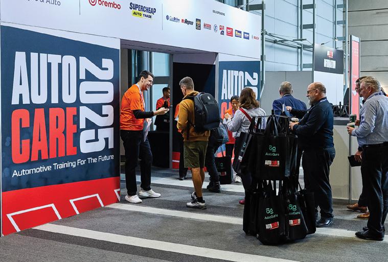
Having just returned from AutoCare 2025, I can confidently say it was an outstanding event –calling it a ‘successful training event’ would be a major understatement.
It was a flat-out few days. From Friday morning we hit the ground running with a packed schedule of training sessions and presentations. Choosing which sessions to attend was the hardest part – they were all so good!
The international guests – Brandon Steckler, Keith Perkins and Tommi Oliva – delivered incredible value and were complemented by the best trainers from across Australia.
Feedback I received throughout the event was nothing short of exceptional. Everyone I spoke to agreed it was well worth their time and investment.
Add in a couple of social events on the Friday and Saturday nights – along with long days of manning the stand – and this ageing technician slept very well after it all.
Huge congratulations to the team at the Australian Automotive Aftermarket Association (AAAA) and everyone involved in delivering this flawless event for our industry. Make sure you lock in the dates for AutoCare 2027 now – you won’t want to miss it.
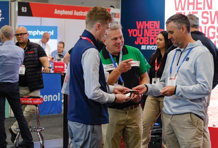
The trade show was also a standout, with more than 120 of the industry’s best suppliers represented (see page 24 for more).
Now that we’re into the second half of 2025 – and doesn’t the year seem to be flying? – I encourage you to keep an eye out for the many training events and conferences happening around the country. Get yourself along to one (or more) and continue to build your skills. I certainly hope to catch up with many of you before the year’s out.
You may have noticed some recent improvements to the TaT website, especially around the enhanced profiling of our artificialintelligence (AI) technicians, Tina and Tony.
Tina now has full access to all areas of our website and all its technical information –including Repair Solutions, scope/scan data and technical-training videos – so she can better answer your questions, provide repair advice and link you directly to the relevant information.
If you’re a TaT member, ensure you’re using Tina as often as needed. She’s like having a highly experienced, professional technician available 24/7. Based on what I’ve seen from her latest updates, her support is awe-inspiring.
Tech Tony, Tina’s brother, is located in our Technical Assistance section and the first responder to any technical-assistance case logged by members on the website. His replies are thoughtful, accurate and of real value to those who lodge cases.
We honestly think Tina and Tony alone are worth the membership fee. And we’ll continue refining and enhancing their capabilities to ensure you get the best AI-powered support available.
As always, your feedback on Tina and Tony is most welcome – shoot me an email any time. Happy diagnosing, guys and girls.

Brendan Sorensen
Every technician has their goto greases. But with the tough conditions seen by 4x4s, it pays to reconsider what’s actually inside those cartridges and tubs – and whether a better option might exist for the specific application at hand.
This isn’t about telling anyone they’ve been doing it wrong. It’s about sharing hard-won insights, understanding failure modes and getting deeper into how grease selection can genuinely improve service outcomes, especially in harsh Australian and New Zealand operating environments.
Beyond the tube –
Understanding grease behaviour
At a basic level, all greases are made of:
• Base oil: Provides the lubrication.
• Thickener: Gives the grease structure – typically lithium, calcium sulphonate, polyurea, etc.
• Additives: Enhance performance –molybdenum disulfide (moly), PTFE, ceramic, antioxidants, tackifiers. The conditions a component operates under determines which grease will perform best:
• Hydrodynamic: A full film of oil separates surfaces – less dependent on additives.
• Boundary: Direct metal contact occurs – grease additives do the heavy lifting here.
Most grease-lubricated 4x4 components operate under boundary lubrication – think uni-joints, swivel hubs, leaf-spring hangers. This is where grease composition and additive chemistry matter most.
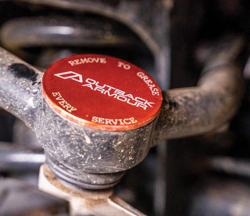
Suitable suspension and driveline items should be greased every service.
Lithium complex grease
• Base: Mineral or synthetic oil with lithium complex thickener.
• Temperature range: ~250°C dropping point (when grease changes from semisolid state to liquid).
• Performance: Good oxidation resistance, average water resistance.
• Use case: Uni-joints, ball joints, tie rods, wheel bearings.
Note: Over-greasing can rupture seals –stop pumping the grease gun immediately as the boot starts to swell or grease just starts to purge.
Calcium sulfonate complex
• Key trait: Inherently resistant to water and corrosion – no extra additives needed.
• Temperature range: ~260–300°C.
• Use case: Grease nipples on leaf shackles, towball receivers, steering links in wet or coastal conditions.
• Advantage: Retains structure and film integrity after water exposure.
Molybdenum disulfide (moly) grease
• Temperature range: ~200–230°C.
• Role of moly: Solid lubricant that embeds into metal surfaces, reducing friction and wear under high loads and low movement.
• Best use: Driveshaft slip assemblies, swivel hubs, spring hangers.
Polyurea grease
• Seen in: OE sealed hub and bearing assemblies (e.g. Toyota).
• Benefits: High oxidation resistance, low bleed rate, long service life.
• Use case: Sealed bearings, electricmotor bearings.
Warning: Not compatible with lithium complex or calcium sulfonate grease – clean thoroughly before switching.
Anti-seize compounds
Type Temp range Best use
Copper-based ~1000°C
Nickel-based ~1400°C
Aluminium-based ~870°C
Ceramic grease
• Composition: Synthetic oil with boron nitride or similar ceramic particles.
• Properties: Extreme heat resistance (>1200°C), non-conductive, stable under caliper heat cycling.
• Best for: Brake slide pins, common-rail diesel (CRD) injector bodies.
Note: Some poorly formulated aftermarket blends dry out – this is due to carrier oil volatility, not ceramic itself.
Red rubber grease
• Base: Castor oil with calcium soap thickener.
• Designed for: Rubber compatibility –especially EPDM seals
• Use case: Caliper pistons, clutch master/slave seals.
• Limit: Not suitable for metal-to-metal, high load or high heat (e.g. brake-pad ears).
Silicone and PTFE grease
• Attributes: Inert, rubber-safe, hydrophobic.
• Best for: Polyurethane bushes, weather seals.
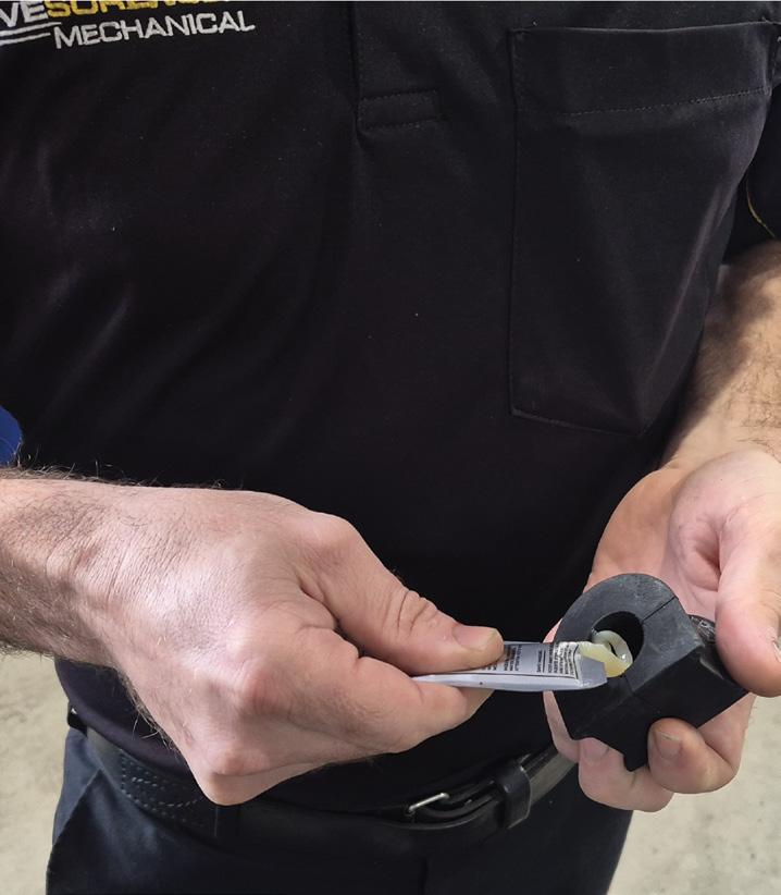
Note: Dielectric grease is a subtype of silicone grease and should be used generously on electrical connections. The grease is displaced by the pins on insertion, allowing good electrical contact while preventing moisture entry.
Avoid on
Exhaust studs, spark Alloy threads (promotes plugs in cast-iron heads galvanic corrosion)
Turbo flanges, exhaust-gas May be overkill for general use temp (EGT) sensors
Steel bolts into aluminium Anywhere where it may wash suspension components onto rubber (i.e. bushes/seals)
Application-specific recommendations
CV joints – Rzeppa vs tripod
• Rzeppa (outer): Needs moly due to sliding-ball contact under high-angle articulation.
• Tripod (inner): Uses needle rollers. Moly is commonly used but technically incorrect. Needle rollers benefit from non-solid lubricants to allow proper rolling – lithium or polyurea grease without solids is ideal.
Swivel-hub bearings
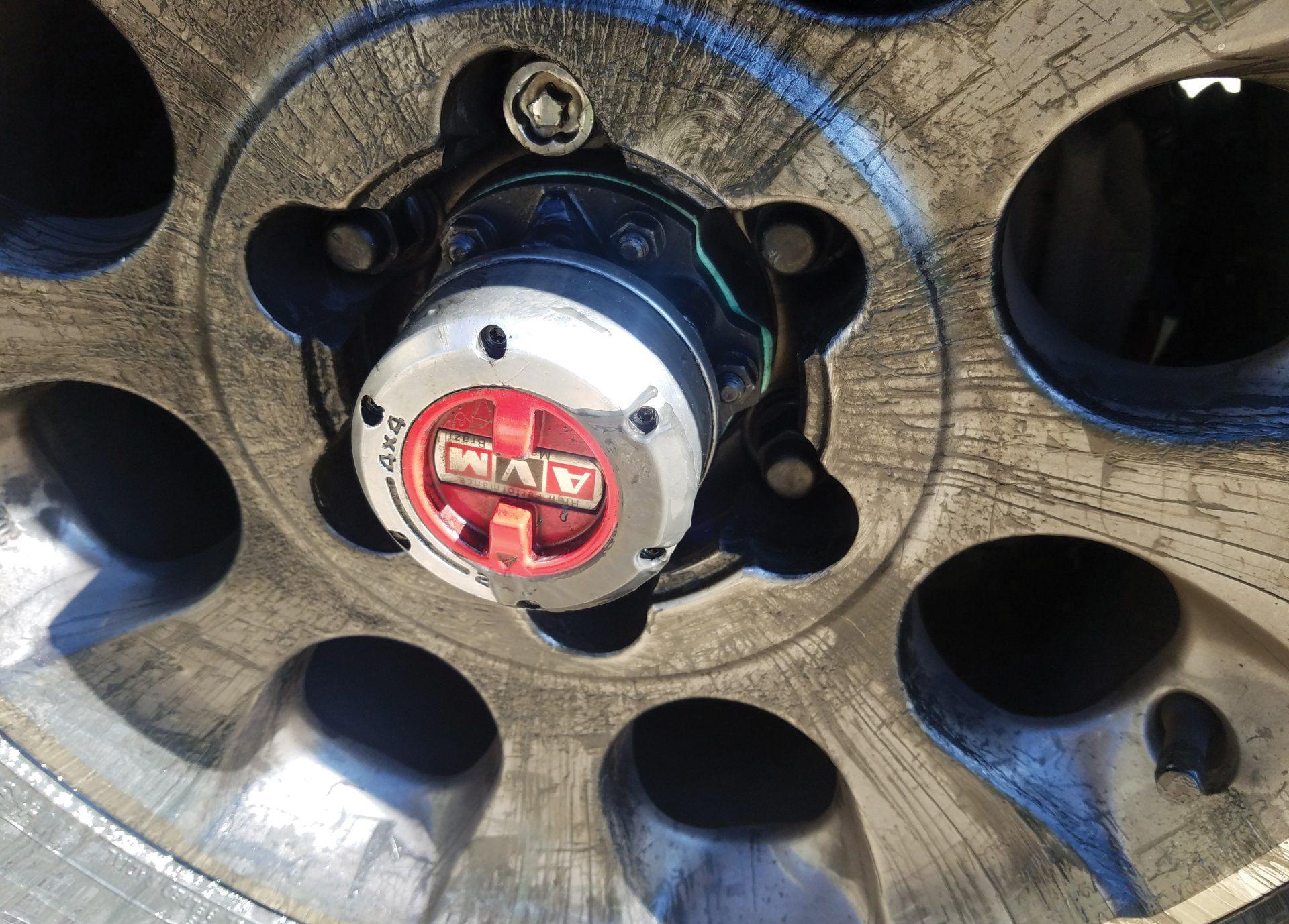
These are low-speed, high-load pivot bearings – sometimes referred to as upper and lower knuckle pivot bearings – and often mistakenly packed with high-speed wheel-bearing grease.
Use moly grease here – it handles the axial and radial loads better under slow articulation.
Leaf-spring bushes
• Where to grease: Inner sleeve (where rotation occurs). Outer casing should stay dry unless designed otherwise.
• Grease choice: For poly bushes, silicone is preferred but moly is acceptable. For rubber, ideally silicone. Using moly is dependent on the grease’s base oil and thickener as this is what can degrade the rubber – just like we see with oil leaks onto suspension bushes – not the moly itself.
Grease choice by environment
•
Brake slide pins

• ceramic grease is the ideal option, many have used rubber grease for decades with no ill effects.
• Never use: Copper anti-seize – it dries out and hardens, which then promotes pin seizure rather than preventing it.
Wheel bearings
Repacking interval is typically ~40,000 km. After cleaning, inspect for:
• Bluing (overheating).
• Pitting/flaking (fatigue).
• Rust (moisture ingress).
CRD injector-body lubrication
Copper anti-seize is still commonly used incorrectly – this creates galvanic corrosion between steel injectors and aluminium heads.
Instead, use ceramic or dielectric grease as specified by OEMs – non-conductive, high-temp stable and will make the injectors much easier to remove later.
Environment Recommended grease
General highway 4x4
Beach/river crossings
Long-haul towing/high temp
Lithium complex bearing grease (NLGI 2)
Calcium sulfonate-based bearing grease
Polyurea or lithium complex with high-temp additives

Yes, there are technically different greases recommended for traditional ball type versus needle
Threaded fasteners – To lube or not?
U-bolts
If lubricated, reduce torque by 20 per cent. Apply grease evenly on threads and under nut face. Retorque after 500-1000km.
Wheel studs
Torque specs are dry – but many techs apply a light smear of anti-seize or oil to studs. It’s a hot topic at the pub but lightly lubing is valid – provided you adjust torque accordingly to account for the reduced friction. Reduce torque by 20 per cent.
Anyone who has battled a seized wheel nut on a bush track knows real-world reliability trumps textbook theory.
Toyota airbox sealing – A known weak spot
Name a Toyota diesel model and chances are it is known for dusting engines via poor filter-lip sealing.
• Service tip: apply rubber or silicone grease lightly to the filter lip.
• Permanent fix: use sealing inserts or aftermarket improved air filters or airbox assemblies.
Did you grease that?
In most workshops grease selection isn’t seen as a hot topic – but it should be. Understanding where a lubricant’s chemistry helps or hinders can mean the difference between a long-service repair or premature failure.
The goal isn’t perfection – it’s informed consistency and the occasional decision to reach for something better than whatever’s in the gun.

Australian workshops face unique challenges: a vast mix of vehicles – from Asian and European to local makes – and harsh local operating conditions.
To meet today’s demands, technicians must combine effective diagnostic processes with advanced equipment, always employing a methodical approach.
In this article, I’ll give you a guide to the essential diagnostic tools, up-to-date equipment and practical tips, with explicit references to online waveforms and scan data suitable for the Australian market.
Traditional diagnostic tools
Visual and physical inspection
Here in Australia, the climate extremes (dust, heat, humidity) demand special vigilance for:
• Wiring chafing: For various reasons.
• Corroded connectors: Especially under-bonnet earth points.
• Brittle plastic intake hoses and connectors: Heat and UV exposure are common culprits.
Never underestimate the power of touch and sight. A simple wiggle test of connectors or flexing a loom while monitoring live data can reveal elusive intermittent faults.
Basic test gear
• Multimeter: Preferably with auto-ranging and min/max record.
• Test lamp/logic probe: Very old school but still a valuable piece of test equipment.
• Vacuum gauge: Still essential for checking manifold pressure on petrol engines, albeit far less relevant for diesels, though still required in some cases.
• Pressure gauge: Ensure yours reads up to 2500 bar for modern diesel rail pressure.
• Stethoscope, mechanical fuelpressure gauge (PFI) and smoke machine: For intake/evaporative emissions control system (EVAP) leaks.
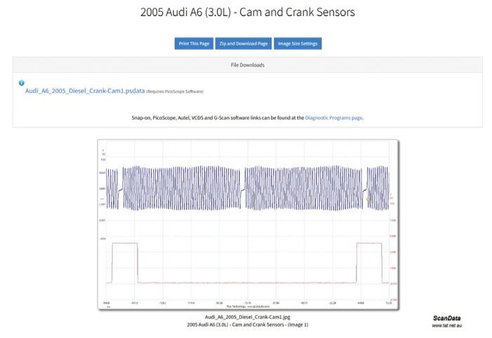
Scopes are fundamental for live/visual checks. Any timing or correlation check (e.g. camshaft versus crank on timing chains – a notorious Holden and Mazda issue) is best done with a scope. Some examples:
• Cam/crank-timing correlation: Video guide for Holden Commodore (VZ, 3.6L): tat.net.au/scandata/videoshare/videoview.php?videoid=vnwxzqjoncU
• Good cam/crank waveform example: From TaT scan and scope data (pic 1).
Modern electronic diagnostics
Scan tools
• Universal OBD2/EOBD scanners: Ideally localised for Australian-delivered vehicles with local technical support and updates.
• OEM-level PC software: Ford/Mazda (Forscan), Toyota (Techstream), Holden (GDS 2) and Hyundai/Kia (GDS). Many scan tools now offer Australian software support and database updates.
Tip: Australian vehicles, even with the same badge as UK/Europe, may have unique emissions components or control variants.
Advanced test procedures
• Live data monitoring: Essential for cross-reference checks such as airflow (mass air flow [MAF]), manifold absolute pressure (MAP), engine coolant temperature (ECT), oxygen (O2) sensor readings.
• Bi-directional controls: Activate components (exhaust-gas recirculation [EGR], fans, purge solenoids) to isolate electrical versus mechanical faults.
• DTC prioritisation: Always resolve the root cause before clearing secondary

3
4
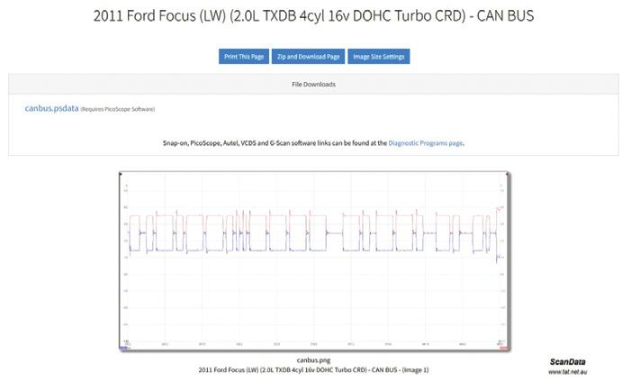
codes. For instance, a controller area network (CAN bus) issue or communication fault code can cascade across the instrument cluster, the heating, ventilation and a/c (HVAC) module and powertrain module.
Some examples:
• CAN bus good waveform: Ford LW Focus (pic 2).
• Injector waveform: Audi (pic 3).
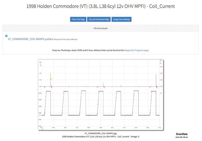
• Coil-current test: Holden VT Commodore (pic 4).
Specialist equipment
Smoke machine
For intake/EVAP/boost leaks: Always use a smoke machine as the first pass, especially for post-diesel diesel particulate filter (DPF)/EGR repairs. Use at gentle pressure (1-2 bar), enough for visibility but not to disturb components.
On turbodiesels in Australian conditions, watch for small leaks caused by red-dust ingress near hose clamps and intercooler tanks.
• Timing correlation: Confirm the pattern against local database waveforms (Holden Commodore timing).
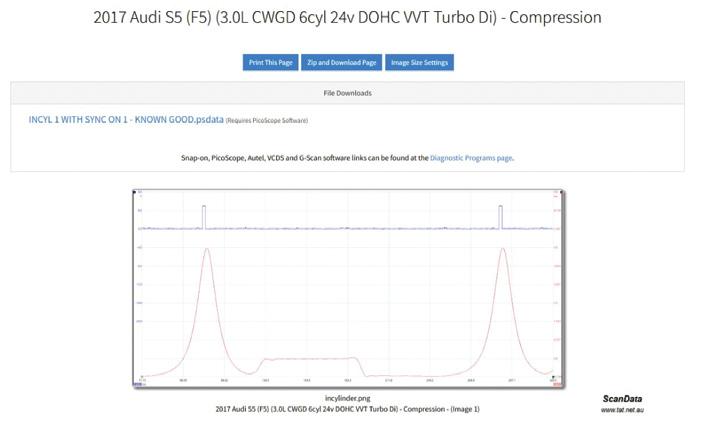
• Compression testing (starter current): Audi S5 example (pic 5).
• Injector analysis.
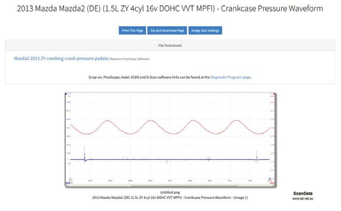
• Crankcase pressure: Mazda 2 example (pic 6).
Scope at accessible points (OBD socket, main loom joins).
For intermittent network drop-outs, check body earths, especially the driver’s footwell and boot. Check for any water ingress.
Top tips for the Australian aftermarket technician
• Local knowledge: Check for technical bulletins and TaT case studies specific to Australian-delivered vehicles. A powertrain control module (PCM) reflash is a common fix for Australian Mazda 3/ Holden Cruze P2096 faults.
• Aftermarket add-ons: Spot check for poor UHF/LED bar or alarm installs, especially wiring around main fuse boxes.
• Smoke machine first: Before chasing sensor ‘out of range’ codes, use a smoke machine to rule out air leaks.
• Scope it: Any hesitation, misfire or network fault – compare your waveform to a local, RHD-specific known good for the exact model.
• Battery support: Always maintain minimum 12.6V – preferably via a batterysupport unit – during diagnostic scan and module programming.
• Education and support: Regularly attend aftermarket training sessions so you will be ready for that next challenging job.
Reference waveforms and scan-data links – Australian context
• TaT scan and scope data (full library): tat.net.au/scandata/
• CAN bus (Ford LW Focus): tat.net. au/scandata/vehicles.php?category= Waveform&system=Network&component= CAN+BUS&make=Ford&vehicle_id=1096
• Injector (Audi): tat.net.au/scandata/ vehicles.php?category=Waveform&system= Powertrain&component=Injector&make= Audi&vehicle_id=312
• Cam/crank (Audi): tat.net.au/scandata/ vehicles.php?category=Waveform&system= Powertrain&component=Cam+and+Crank+ Sensors&make=Audi&vehicle_id=373
• Compression (Audi S5): tat.net.au/ scandata/vehicles.php?category=Waveform &system=Powertrain&component= Compression&make=Audi&vehicle_id=1117
• Crankcase pressure (Mazda DE 2): tat.net.au/scandata/vehicles.php?category= Waveform&system=Powertrain&component= Crankcase+Pressure+Waveform&make= Mazda&vehicle_id=774
• Cam/crank correlation guide (Holden VZ Commodore video): tat.net.au/scandata/ videoshare/video-view.php?videoid= vnwxzqjoncU
Australian aftermarket technicians are uniquely positioned to combine foundational skills with advanced diagnostic technology. Consult local data, use Australian RHD resources, invest in a smoke machine and quality scope and rely on waveforms and scan data as your benchmarks. The right support and a methodical approach make diagnostic challenges manageable, no matter how ‘Aussie’ the challenge.


Clinton Brett
The company formerly known as Siemens VDO claimed to be the first to patent the common-rail diesel (CRD) fuel system.
Continental, the well-known European tyre manufacturer, purchased a large stake in the company and took over ownership rights, after which the fuel system was renamed.
This was also, in my opinion, the beginning of a decline in the company’s product quality. Siemens had produced one of the most reliable CRD systems around. This system is mostly fitted to PSA Powertrain (Peugeot Société Anonyme) products – PSA being a manufacturer of petrol and diesel engines for a range of companies including BMW, Ford, Jaguar and Land Rover.
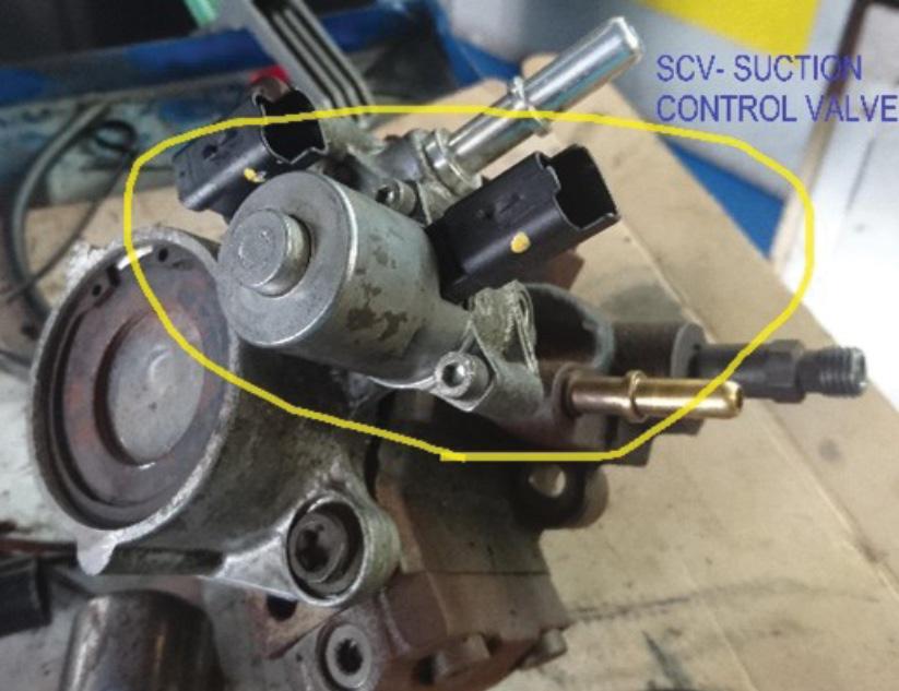
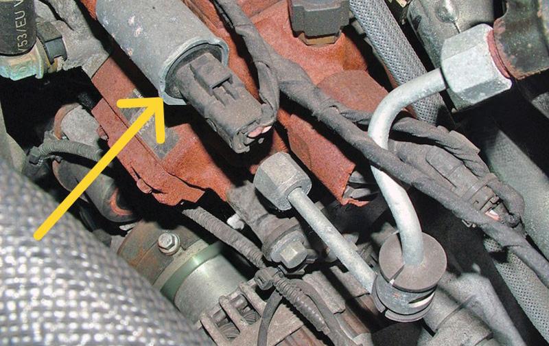
Like many control-valve failures, contamination has been the biggest cause of failure in this Continental-branded suction-control valve (SCV). Most often, metal fragments have been known to seize the internal valve.
This metal, in the early Ford PX1 Ranger, was a result of failed plunger springs in the high-pressure (HP) fuel pump (pic 1). The metal would simply recirculate through the entire fuel system.
The breakage rarely stopped the car completely in its tracks and often the SCV (pic 2) was blamed for the fault. It was not until finding the fault remains after replacing the SCV that true source of the problem was found.
Apart from that misdiagnosis, these valves have been known to fail, often causing a non-starting situation or, in some cases, HP fault codes and limp mode. They are generally a normally open type but when they are unplugged and an attempt is made to start the engine, they often fail to do so due to the open circuit within the system.
Common symptoms include:
• Poor performance, especially under load or towing.
• Check-engine light (CEL) on.
• Torque reduction/limp mode.
• Fuel pressure-related fault codes such as P0089 – Fuel pressure low, P2291 – Injector control pressure (ICP) and P228C – Fuel pressure regulator exceeded performance.
An amp-clamp test can assist in determining if they have failed but remember, if there is increased amperage then metal/ contamination could be the cause; therefore, the pump must be replaced.
The following is taken from Diesel Help Australia’s very own technical bulletin TB1002 Ford Ranger P0089, P2291, P228C Fuel System Faults: While cranking, inspect the amperage change. Maximum amperage must be no greater than 2A. When a control valve is seized, the amps will increase.
Bosch FMV
It’s not just fuel-system manufacturers creating their own terminology, OEMs also do so. Cummins, a regular customer of

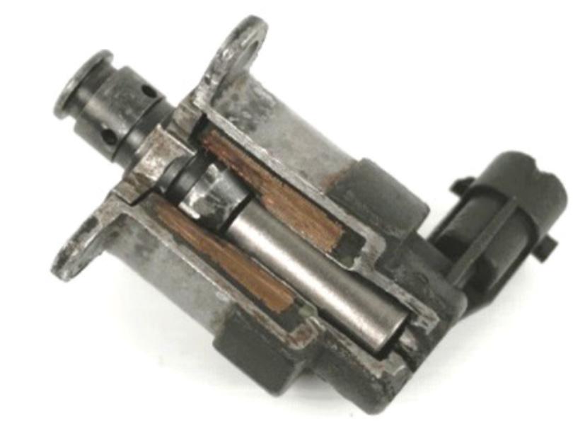

Bosch, refers to this metering valve as the pressure-regulating valve (PRV), quantitycontrol valve or fuel-volume control (FCV) valve.
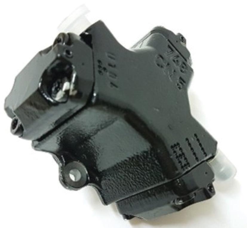
The fuel-metering valve (FMV), the most common name for this Bosch component (pic 3 and 4), is located on Bosch CP3 highpressure fuel pumps (pic 5).
Most of these Bosch valves are of the normally open type, meaning the valve moves into a high-flow position whenever they are disconnected, immediately increasing the rail pressure.
When a rail-mounted fuel-pressure regulator is fitted, the ECU recognises this change and demands the regulator, which is located on the rail, to compensate and retain a stable rail pressure. We have demonstrated this on a Volkswagen Amarok and you barely hear the engine change, nor do you see a change in the fuel-rail pressure.
Some systems using a normally open type have no pressure regulator and when the same action occurs, the rail pressure increases without complete control to reduce the pressure.
For example, if you unplug the Isuzu D-Max, the rail pressure climbs to 100 bar above the desired level, the engine runs rough and a harsh rattle occurs.
An earlier design fuel pump, the CP1, does not have any valves fitted to the body of the pump (pic 6).
So how does a CRD pump operate without any control valves?



The engine has a cam-driven lift pump which draws the fuel from the tank, then transfers it to the three-plunger HP fuel pump. This can create fuel-rail pressures of up to 1600 bar, which is regulated by the injectors and a pressure regulator located at the end of the rail.
Some CP1 pumps are fitted with a third cylinder shutoff which is positioned on one of the plungers. This assists in shutting down the engine by opening a valve to drop the fuel pressure (pic 7).
A later version, the CP1H3, was fitted with an FMV and uses using this basic rotary-design pump. It has been used in Mercedes-Benz Sprinters and Vito models,.
This pressure-regulating valve (PRV) controls the high pressure in the fuel system
and is often located after but mostly found in the fuel rail.
Unlike most other CRD systems, where the pressure regulator is in the rail, Continental locates this pressure regulator in the pump on the HP output gallery (pic 8 and 9).
Depending on certain periods of operation, it acts to reduce pressure. It operates to control rail pressure mainly when:
• Starting: PRV is held wide open.
• Decelerating: Dumps excess pressure.
• Failsafe: PRV is faulty.
In the six parts of this series on fuelcontrol valves so far, we’ve completed our discussions on the valves found on pumps. In part seven, I’ll explain some of the valves located on the rails and how they can be simply diagnosed without a scan tool.


Australia’s top emerging tradespeople showcased their skills at the 2025 WorldSkills Australia National Championships & Skills Show, held at the Brisbane Convention & Exhibition Centre from June 12 to 14.
The event attracted a record 35,000plus visitors and featured the talent and dedication of more than 600 competitors across more than 60 categories – including Auto Electrical, TVET (Schools) Automotive and Automotive Light Vehicle Mechanical. In the automotive sector, TAFE NSW Mount Druitt students delivered outstanding performances:
• Charlie Vella, studying a Cert III in Automotive Electrical Technology, took home bronze in Auto Electrical.
• Callahan Smith, also completing a Cert III, earned a Medallion for Excellence in the Light Vehicle Mechanical category.
While only the Light Vehicle Mechanical category results in international representation at the WorldSkills International
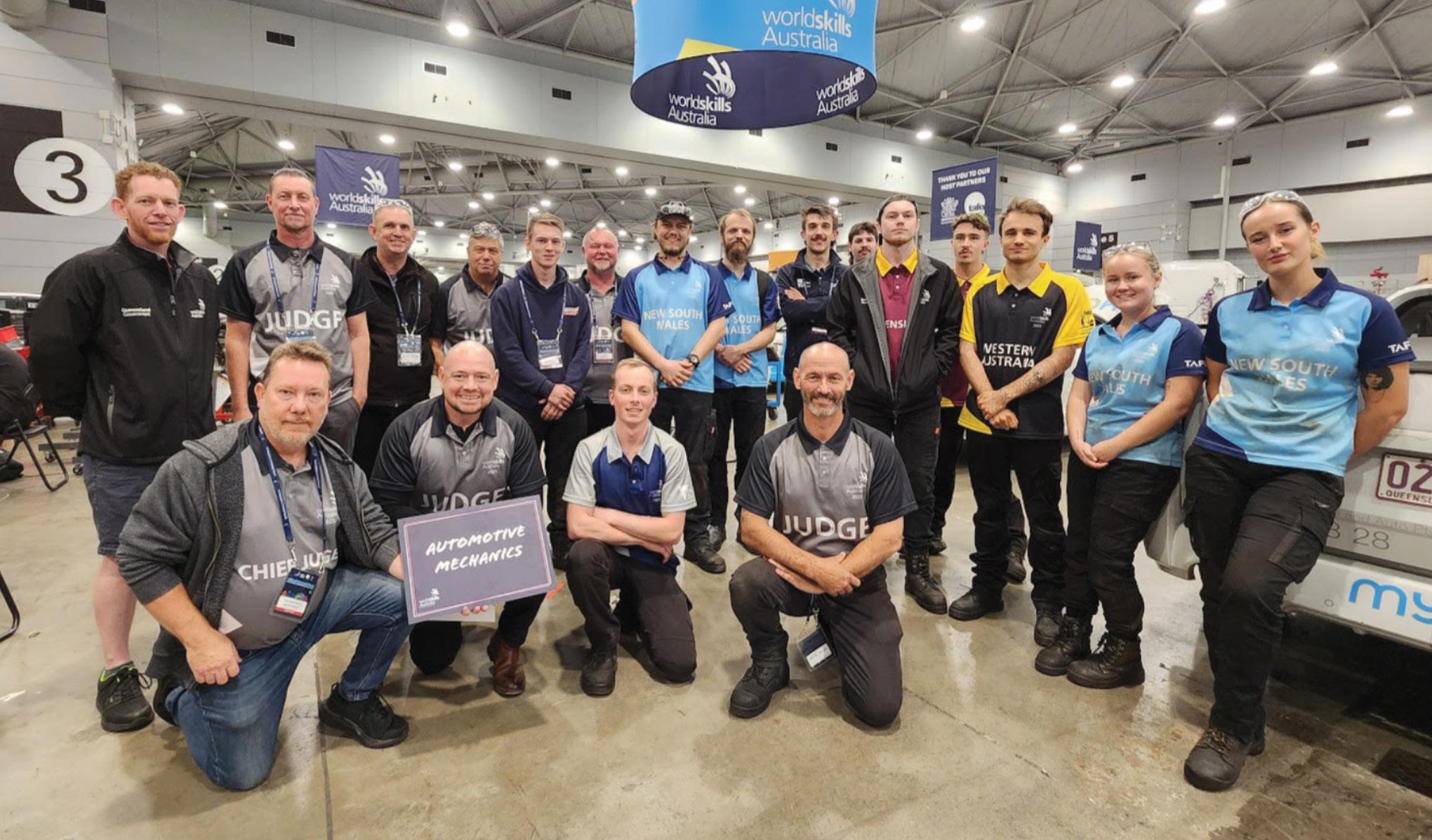

Competition in Shanghai (due to the absence of Auto Electrical and School-level categories), Vella’s podium finish puts him in strong contention for selection to the Australian Skillaroos team.
‘These competitions are a chance to not only showcase talent but to fast-track careers and confidence,’ said TAFE NSW Managing Director Chloe Read. ‘They also reflect the strength of our vocational training and the value of industry-led mentorship.’
All competitors train during their own time, with industry and education volunteers offering their expertise and effort to make these events happen – a strong reminder of the community that supports Australia’s automotive-training system.
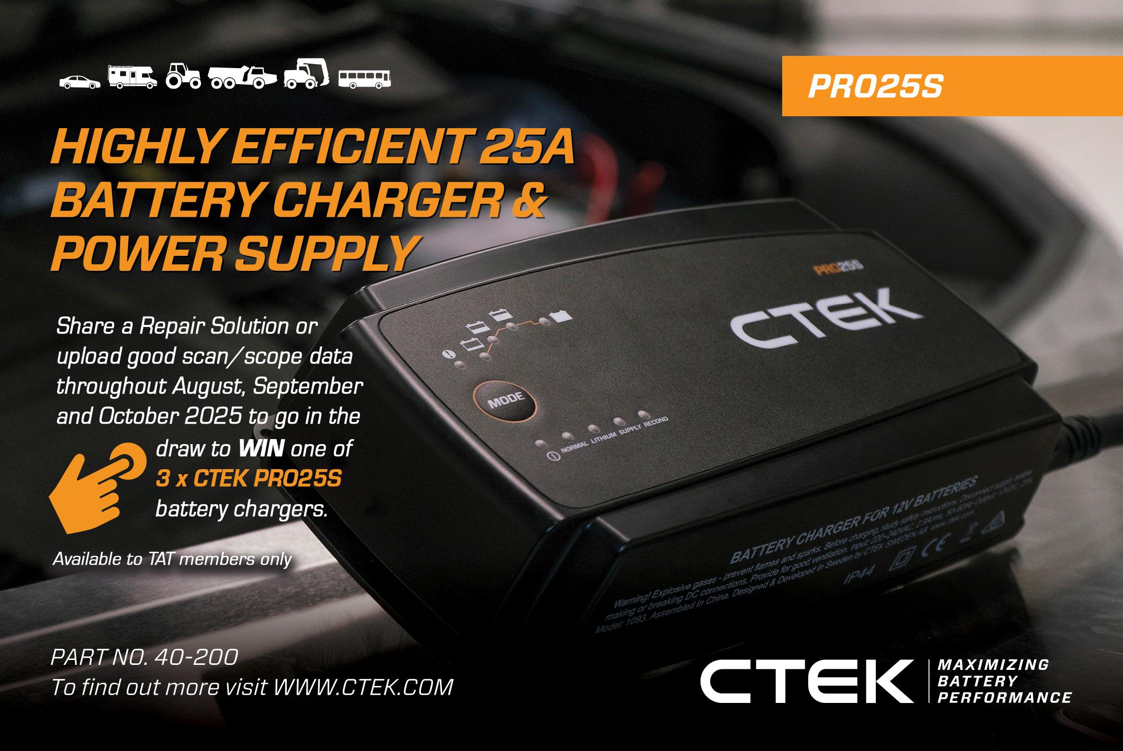
Battery support is an essential part of modern workshop practices and this applies to all workshop services, even in minor cases.
As vehicles get more technically advanced, the need for battery support increases. When you open a car door and everything turns on, all of this energy comes directly from the battery. A modern vehicle has more than 200 ECUs controlling many of its functions.
For the workshop, battery support in connection with service is a matter of technical safety and offering a complementary service to the customer and security for the company brand itself.
Whether you are repairing a car, testing electrical circuits, carrying out diagnostic procedures or flash-programming ECUs, battery support is a vital activity often not fully appreciated for its importance in saving technicians time. It can also insure against costly programming failures and prevent possible costly damage to the ECU.
The reprogramming of ECU modules and fault-code diagnostics requires the ignition switched on without the engine running. This means the vehicle’s systems are operated solely from the power of the battery during programming and maintaining battery

charge is critical to avoid unnecessary downtime, lost data or even damage to sensitive electronics.
‘Battery support’ – as distinct from charging – is vital for the supply of clean, constant voltage for programming. It can also guard against loss of battery charge, protecting the battery from discharge when the work is complete and the vehicle is back out on the road.
Should battery voltage alter significantly during reprogramming, the programme can fail – meaning a time-consuming restart or, worse still, an ECU damaged beyond recovery and requiring expensive replacement.
Using equipment dedicated to battery support is now a necessity in the modern workshop.
The PRO25S from CTEK is designed to meet the intense power demands in any workshop. It’s capable of supporting 25A charging at 12V and compatible with any 12V battery, including lithium batteries.
The PRO25S is designed to restore charge and recondition batteries using a patented multi-step charging process, with a dedicated reconditioning programme allowing the operator to restore or rescue any battery.
• To find out more go to ctek.com
A 2007 Holden VE Calais came in for a roadworthy and the ‘Service Vehicle Soon’ light wouldn’t clear.
After a full scan, all codes were cleared except one — C0899 in the anti-lock braking system (ABS) module. It wouldn’t budge.
C0899 is a control module power-circuit fault. We pulled up the wiring diagram and checked all power and ground supplies to the ABS module. Everything tested fine. We dug into past ABS issues on TaT, having seen plenty of problems with VE modules before. Most other cases had C0899 appearing alongside two or three additional codes, often wheel-speed sensor faults with broken wires. But in this case it was only C0899.
The job was squeezed in around other work, so we didn’t have much time to chase further. That’s when the new owner
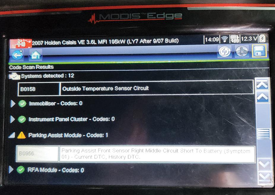
mentioned the original owner had been told by a dealer that the problem was an ambient air-temperature sensor.
The dealership tech claimed the ambient sensor would resolve all the issues. The owner brought in a new one and asked us to fit it.
I told him I couldn’t see the correlation between an ambient-temp sensor and an ABS code but was happy to fit it anyway, at least to clear the ambient fault. I even joked, ‘I bet you a box of beer this won’t fix the ABS code.’
I’m glad he didn’t take me up on the bet. To my complete surprise, the moment we plugged in the new sensor the servicevehicle warning disappeared and all codes cleared and stayed cleared.


I’m sharing this purely to help the next tech who gets stuck with a single C0899. I would have easily wasted hours on this or maybe even sent the ABS unit away for testing.
No deep diagnostic lesson here — just one about bets and keeping your cake hole shut.
Hope it saves someone else the time!
Anthony Tydd Briggs Automotive BENDIGO, VIC


The Australian Automotive Aftermarket Association (AAAA), together with the broader industry, recently had the privilege of presenting Stephen Kasapis with a Special Recognition Award prior to his passing on June 27, celebrating his outstanding leadership, deep industry knowledge and unwavering support for his peers across Australia’s automotive service and repair sector.
Stephen’s legacy is one of generosity, integrity and tireless contribution. From lifting workshop standards to mentoring the next generation, he made a lasting impact, both nationally and internationally.
Thank you, Stephen. Your service shaped the industry and your legacy will live on.
Maurice Donovan was the one to alert the AAAA that Stephen’s health had deteriorated and put forward the idea of an award and the idea gained significant and broad support from everyone in the industry.
‘What an honour to be there to present Stephen Kasapis with this well-deserved award,’ said Maurice. ‘I truly believe Stephen deserved this award more than anyone that I know in the industry.
‘I have known Stephen for many years and I can say without exaggeration he was one of the most knowledgeable automotive technicians in the country.
‘What truly sets Stephen apart, however, is not just his expertise but his unwavering passion for the industry – and more importantly, his generosity in giving back to it. Even from his sickbed and while in excruciating pain, Steve was still on the phone helping another technician diagnose a complex issue.’
From everyone in the industry, congratulations Stephen, you 100 per cent deserved this acknowledgment.
- Jeff Smit

In life, we cross paths with many people but some leave a deeper, more indelible impression.
When I first met Stephen Kasapis many years ago, I thought of him as a decent sort of bloke. But as I got to know Steve – as I came to call him – I soon realised just how much depth lay behind his quietly spoken manner.
Engage him in a conversation about automotive technology and suddenly he wasn’t quiet at all. He came alive, his eyes sparkling with an infectious enthusiasm. Steve didn’t just work in the industry – he lived and breathed it, every fibre of his being dedicated to its advancement.
He once told me he’d attended every Bosch course available in the 1980s and ‘90s. His work colleagues would rib him – ‘Why bother learning about fuel injection? Everything we touch still has carburettors.’ Steve would simply reply, ‘Wait and see’ and as history unfolded, Steve, ever the visionary, had the last word.
I can’t pin down the exact year I met him – likely sometime in the 1990s – but around 2010 Steve bailed me up and began speaking with genuine enthusiasm about the technologies reshaping the modern vehicle. He’d seen some of my TaT articles and was eager to connect with someone who shared his obsession. That shared passion cemented our friendship but it was his unparalleled dedication and quiet brilliance that truly set him apart.
Steve’s interests reached well beyond the workshop. Latin dancing was one of his great loves, a joyful counterpoint to his technical mind. On a training trip to Canberra, once our training had wrapped up in the evenings, Steve would head off to a Latin dance club, full of rhythm and joy.
He was also a keen cyclist, clocking up countless kilometres and relishing the outdoors. Before he became too ill to ride, I had the immense pleasure of joining him on one of his morning rides – an unforgettable experience capped off with a cafe breakfast and great conversation.
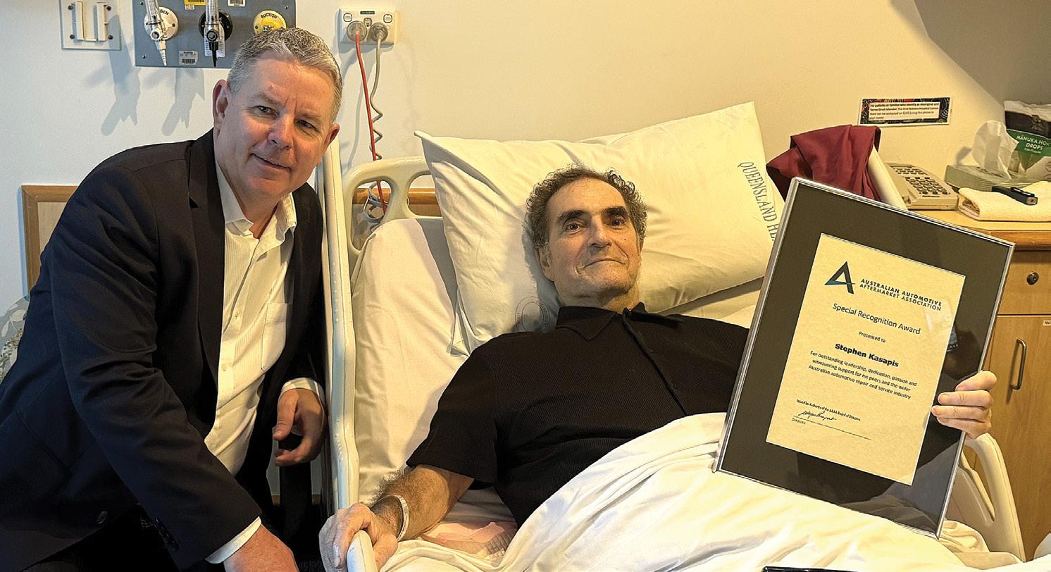
Despite his declining health, Steve headed off to the Gold Coast that very same day to attend an Automotive Air Conditioning, Electrical and Cooling Technicians of Australasia (VASA) training event. That was Steve: never idle, always learning, always pushing forward, right to the very end. His insatiable thirst for knowledge took him to the UK, where he learned from greats such as Frank and David Massey, Darren Darling and Steve Scott. In Frank Massey’s workshop, Steve would be handed the toughest diagnostic jobs – and he’d return, ready for the next, before anyone expected him to be. They were stunned. I wasn’t. One of Steve’s proudest achievements was bringing Darren Darling’s DPF Doctor network to Australia. Thanks to his time with Darren, Steve not only mastered diesel particulate filter (DPF) diagnostics and repairs but also became a driving force in spreading that knowledge locally. He didn’t just build a network – he laid the foundation for a culture of continuous learning and support, shaping the skills of countless technicians.
Soon after the news of Stephen’s passing, Darren Darling himself shared, ‘What I can tell you is that he has left a legacy that will not be forgotten. The messages and calls I have received here in the UK and abroad from members of our network have
been monumental as he touched so many people’s hearts all over the world.’
It’s truly hard to capture the full impact Steve had on the automotive industry – and on all of us who knew him. His technical expertise was exceptional, yes, but what really set him apart was his boundless generosity. He was a mentor, a problem-solver, a quiet leader and a steadfast friend. If someone had an issue that no one else could solve, they called Steve. And time and again he delivered with patience, wisdom and genuine care.
On one of my hospital visits to see Steve, I was struck by his unwavering spirit. I could see how sick he was and how much pain he suffered but he was sharing how he was still helping the trade solve complicated diagnostic problems. He recounted a scenario of assisting someone only the day before. I could not believe he possessed such dedication in his present state. I looked at Tonia, his wife, as if to ask, ‘How could he still be so involved?’ She simply said to me, ‘No, this is good for him, it takes his mind off his sickness and the pain he suffers.’
This moment perfectly encapsulated Steve’s profound commitment to his craft and to helping others, right up until the very end. One of the most touching moments I’ve experienced was being by Steve’s hospital
bedside – with Stuart Charity, Jeff Smit, Mike Carnemolla and Darryl Blacker – when Stuart (AAAA CEO) presented him with a richly deserved industry award. It was a powerful, poignant tribute to a man whose contributions were both profoundly technical and deeply human, a moment forever etched in our hearts.
Steve reminded us all that expertise and humility can walk hand in hand. He showed us being a technician isn’t just about solving problems – it’s about curiosity, compassion and connection.
Now, with aching hearts, we grapple with the immense void he leaves behind. His passing is a profound loss and our sadness at losing such a wonderful person, a true gentleman, is immeasurable.
Yet his legacy lives on vibrantly in the lives he touched, the technicians he selflessly mentored and the brighter future he helped shape for an industry he loved so dearly.
We were incredibly lucky to know Steve, to learn from him and to call him a friend – and the automotive industry, indeed the world, is undeniably better for having had him in it. We will miss him terribly.
- Maurice Donovan
A 2023 Ford UB Everest with just 14,598km on the clock came in from a smash repairer with the message on the instrument cluster, ‘Reverse brake assist not available’.
The issue was related to recent repairs to the rear of the vehicle, including replacement of the rearview camera.
Checked the vehicle for DTCs and found:
• B1B44:08-28 – Right rear outer sensor.
• B1B46:08-28 – Right rear inner sensor.
• B1B48:08-28 – Left rear outer sensor.
• B1BS0:08-28 – Left rear inner sensor.
• B115E:31-28 – Camera module.
• B115E:15-28 – Camera module.
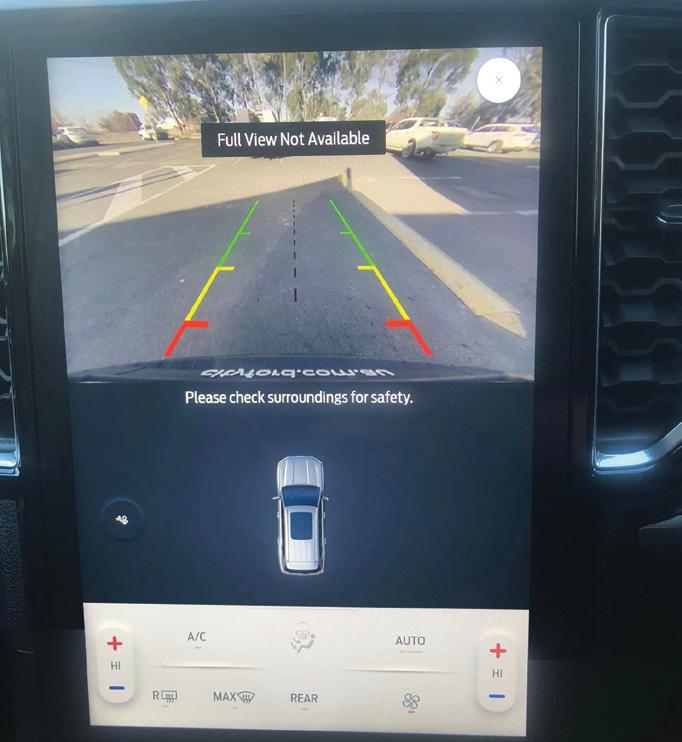
Various other codes were present in different modules, mainly related to disconnected fog lights and similar.
I contacted Ford tech and TaT member Robbie Oakley for some guidance. He advised it would likely need a 360-degree camera calibration — and noted a simple rearview-camera calibration usually doesn’t work, even with factory tooling.
Tried the rearview-camera calibration first and as expected, it didn’t resolve the issue. Carried out a full 360-degree camera
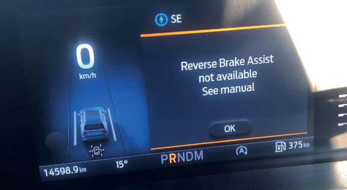
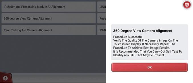

calibration using a ThinkTool Expert 195, which worked perfectly.
The system restored full 360-degree view functionality, and the reverse brake-assist warning was cleared.
Diagnostic time for this job was 10 minutes and repair time 20 minutes.
Gary O’Riain GO Diagnostics
GULGONG, NSW

The vehicle, an RG model with 157,000km on the clock, would crank but not start.
Spoke with customer and they said the NRMA had been out and checked codes. They found a code related to the crankshaft position sensor (CKP), so had replaced it with an aftermarket sensor, but the car still would not start.
Verified the customer’s concern. Attempted to start the car and it intermittently fired on random cylinders but would not start.
Checked the vehicle for DTCs and found:
• P0335-28 – CKP circuit incorrect frequency.
• P0606-33 – Control module processor performance special memory failure.
• P0606-59 – Control module processor performance circuit/component protection time-out
Checked the battery condition – it was dropping below 7.5V during cranking, so required recharge or replacement.
Checked all fuses – they were OK.
Next, checked data. Confirmed the fuel rail pressure – it was OK and within specification (7000psi cranking).
Confirmed the engine speed was reading –it was OK.
Confirmed the mass air flow (MAF) sensor and manifold absolute pressure (MAP) sensor were reading – they were OK. When cranking the engine with injectors connected, the engine sounded very rough and out of time; when cranking with the injectors disconnected, the engine sounded normal/in time.
Carried out a relative compression test –it was OK.
Checked the operation of the injectors, including a back-leak test (super easy to get to) – aside from the very intermittent firing, they were OK.
Checked the operation of the CKP sensor and camshaft position sensor (CMP).
The waveform wasn’t very clear but the CKP signal looked upside down (pic 1).
Confirmed power and ground for the CKP were correct. Confirmed the signal had 5V.


Recommended replacing the CKP sensor. Fitted a genuine CKP sensor supplied by the workshop and fitted, then cleared the DTCs. Attempted to start the vehicle and the P0335-28 returned. Rechecked the CKP and CMP signals and found the waveform was much clearer and now showed inconsistencies with the CKP signal. The waveform showed too many CKP top dead centre (TDC) pulses (pic 2).
Suspected the reluctor/trigger wheel for the CKP was damaged, so contacted the local dealer and confirmed the CKP sensor picked up its position from a tin plate with a magnetic ring on the back of the crankshaft. They also stated they had just done this same repair on another 2.8-litre Colorado, a 2017 model.
Suspected the magnetic ring/pick-up/ trigger/reluctor wheel was damaged and causing the frequency error DTC (P0335-28).
I was called back after the workshop had replaced the trigger wheel and found the car cranked normally but still would not attempt to start – it sounded like no injector activation.
Checked for DTCs and found none, then checked the battery – it was OK – as well as the fuel pressure during cranking, which was also OK.
Checked the CKP and CMP sensor signals and found the CKP signal was now very clear, with no extra TDC marks.
Checked the correlation of CKP and CMP to check engine timing and found the CKP signal was six teeth retarded.
Checked the old/original CKP trigger wheel and found it cannot be fitted incorrectly (locating dowel plus sleeve-style shape). Confirmed correct power, ground and signal voltages at the CKP and CMP. Confirmed the CKP and CMP signals again – it was still six teeth retarded (pic 3).
Contacted a Holden parts supplier and asked for the part number for this car (by vehicle identification number [VIN]) fitted with an LWH engine – it was 12625422. Then asked for the part number for the same part fitted to the next model/facelifted Colorado (changeover in 2013.5/2014, LWN engine) – it was 12637870.
Checked the invoice given to the workshop found the invoiced part was 12637870, the part number for the newer LWN engine.

Note: The P0606 codes were set due to a low/failing battery.
Fault description
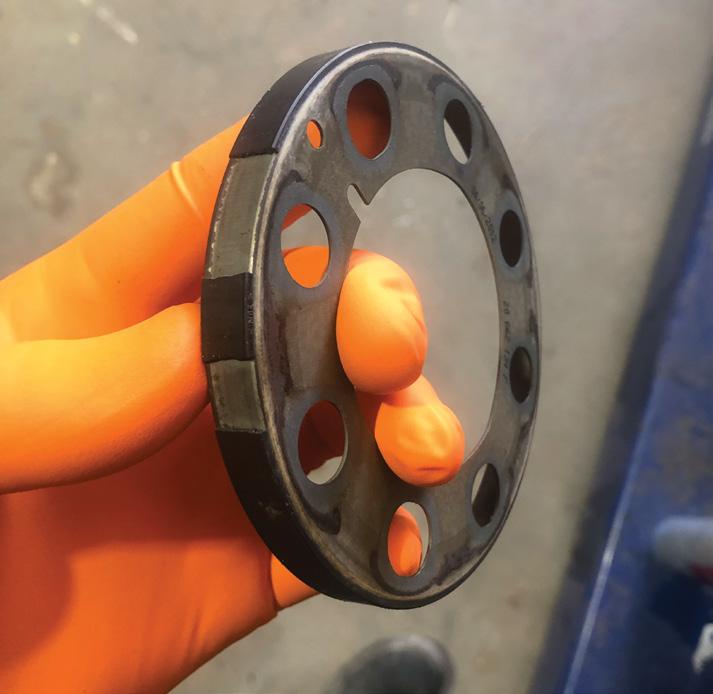
The root cause for the original fault was the damaged trigger/reluctor wheel (pic 4), which was masked by a cheap aftermarket sensor giving an upside-down signal and not showing the extra TDC marks clearly.
After the sensor was replaced, the fault with the trigger wheel was easy to see. The trigger wheel was replaced but the local Holden parts supplier supplied the wrong part.
I believe this happened because I had called the dealer to confirm the CKP signal pickup location and they had just supplied the trigger wheel on a 2.8-litre Colorado for the same issue.
I suspect the parts person, when asked to order for a 2.8-litre Colorado, just decided to re-order the same part to save having to actually look for it in the catalogue. Unfortunately, that was for a 2017 Colorado with an LWN engine, not an LWH.
Fault solution
Replaced the just-replaced, incorrect CKP trigger wheel with the correct part.
I have been advised the car is now working, with no fault codes. I did not perform the parts replacement.
Recommended time
Diagnostic time was 90 minutes, taking into account preparation and research. Repair time n/a.
Repair Solution by TaT Tech Team member Gary O’Riain.

Customer complaint
The vehicle had been booked in for a regular service but felt severely underpowered during the initial road test, as though it was not making any boost.
Problem summary
Carried out a full vehicle scan but no fault codes were stored.
Having a glance over live data in the bay, one thing stood out. The measured airflow matched the required airflow at idle but not as the engine RPM raised – at 2000RPM the measured airflow was 320 milligrams (mg) while required was 480mg.
This was enough to know there was something worth chasing, so after carrying out the full vehicle-service inspection, some diagnostic time was sold to the customer.
Diagnostic sequence
Road-tested the vehicle again and noted on a wide-open throttle pull the desired boost was 2200 millibar (mbar) while the actual would briefly hit 1800mbar and then hang around 1400mbar for the remainder of the pull.
The measured airflow also remained well below the required airflow during the pull. Back in the bay, I had someone rev the engine while I viewed the turbo vacuum actuator moving smoothly, which was surprising as it felt like the turbo vanes were stuck in low-boost mode.
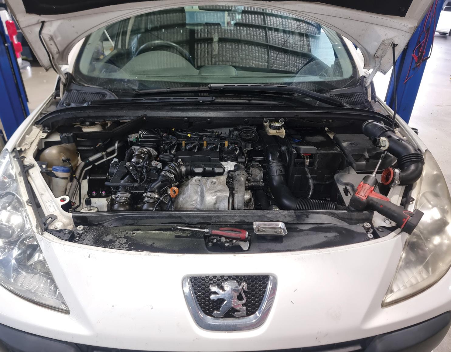
The service history showed this vehicle had jumped around to different shops and in these Peugeots the air filter is in a pretty


1
terrible area, so when I actually checked it during the service it was quite dirty – not blocked enough to be the problem, but overly dirty.
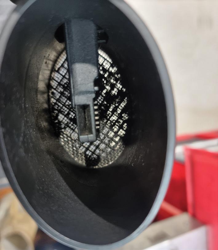
This made me think I better at least have a look at the mass air flow (MAF) sensor (pic 1).
What I found was a remarkable level of build-up, not so much on the MAF itself but the air-straightening grid before the MAF itself (pic 2).
Cleaning the MAF and its air grid restored full performance.
2
Fault description
Debris build-up on the MAF sensor’s built-in air grid.
Fault solution
Cleaned the MAF and its air grid.
Recommended time
Diagnostic time was one hour, taking into account preparation and research. Repair time was 15 minutes, taking into account the location of parts and carrying out the repair to a tested outcome.
Repair solution provided by TaT Tech Team member Brendan Sorensen.
The instrument cluster, door lights and interior lights were not working.
The vehicle was brought in from another workshop after a dome light had been replaced.
The other workshop had been in possession of the vehicle for three weeks. During that time, the battery had been drained several times.
The instrument-cluster issue and all other complaints had only occurred after the dome light was replaced.
Looked at the instrument cluster with a torch and the odometer reading could be seen. Because the battery had been drained, I put it on charge – it was later replaced.
Checked all fuses – they were OK.
Suspecting a backlight issue, used scantool activations to see if the dash would come to life. No gauges could be activated and only sections of the dash could be illuminated.
Examined the wiring diagram and found the only connection between the instrument cluster and interior light was the body control module (BCM).
According to the customer, the vehicle was a ‘Police Pack’ variant, so researched the features and found they have a 10pin connector where the ‘civilian’ models contain six pins.
The interior light was also different from the standard light provided by Holden. Disconnected the interior-light module to examine it and the instrument cluster came back to life. Disassembled the circuit board on the module and found a capacitor had come adrift.
Resoldered the capacitor and resoldered

some other suspect components. However, this did not fix the issue.
Gained customer approval to purchase another interior-light module. Fitted the new module but found no difference.
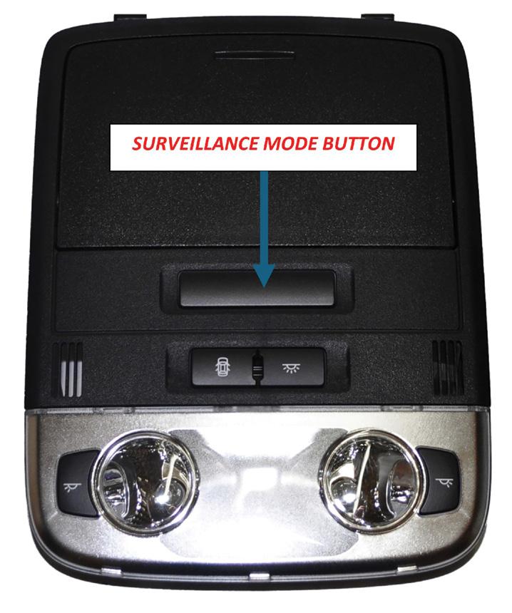
Noted a surveillance button. When pressed, the dash came to life (pic 1). Tried the old module but the surveillance button made no difference.
After researching the issue I discovered an article in the Victorian Automotive Chamber of Commerce magazine stating that when the Police Pack was changed to the ‘civilian’ spec, all of the police-specific features were removed.
However, they did not remove the interior light surveillance mode, so when the battery was disconnected or the interior light globes were replaced, the BCM would revert to a default surveillance mode.
In some cases, the button will be physically removed or a wire will be cut. However, the BCM will still default to this mode, with no way to reset it using the button.
Some scan tools are able to alter this by

going into the BCM under ‘SPS Program’ and setting it to the standard setting.
After replacing the interior-light module, all features of the instrument cluster, as well as the interior lights, were now operating correctly.
Fault description
Incorrect interior dome-light module (police model vs civilian).
Fault solution
Fitted the correct module
Recommended time
Not supplied.
Tips for TaT
For my personal training and curiosity, I disassembled the old interior-light module and found the surveillance mode button had physically been removed (pic 2). This explained why the instrument cluster had failed.
Repair Solution provided by TaT Tech Team member Mark Rabone.


TaT is a unique platform that provides members with practical information and solutions straight from the workshop floor. Information of the kind you won’t find in a call centre, manual or wiring diagram. Sign up at tat.net.au

TaT MAGAZINE: Get Australasia’s No.1 technical automotive magazine mailed to you six times per year, plus search over 2000 pages of past editions online.


REPAIR SOLUTIONS: Get access to over 2500 diagnostic repair solutions searchable by vehicle, problem and fault code. Each fortnight we upload 20 new repair solutions.


DIAGNOSTIC PROGRAMS: Get access to 20 in-house designed diagnostic calculators and software programs.
FAULT-CODE DATABASE: Get access to an electronically logged database of over 8000 fault-code definitions.
GOOD SCAN/SCOPE DATA: Get access to over 17,000 good scan tool and scope-data uploads to compare to the bad data you have retrieved from your vehicle. TECHNICAL ASSISTANCE: Get technical assistance from the TaT tech
us on Facebook @theautomotivetechnician
Customer complaint
The check-engine light (CEL) was illuminated and the vehicle – a TF2 model with 121,803km on the clock – was in limp mode.
Problem summary
A full vehicle scan retrieved the following code:
• P0234 – Turbo overboost condition.
Noted that the freeze-frame data showed 2619RPM, 970 seconds since start, 65km/h and 46 per cent load, but annoyingly did not show boost pressure.
Confirmed the CEL was on, then cleared the fault codes and road-tested the vehicle.
Diagnostic sequence
In the first 30 seconds of the first road test, and under heavy load, the vehicle faulted, setting the same P0234.
Noted that the boost pressure had been very high prior to this – at high load, it was reaching more than 250 kilopascals (kPa). At standstill, I drew up a graph of desired versus actual boost:
• Key-on/engine-off (KOEO) – 101/101.
• Idle – 102/102
• Brake torquing – 169/200
Actual boost was higher than desired even at a standstill brake torque.
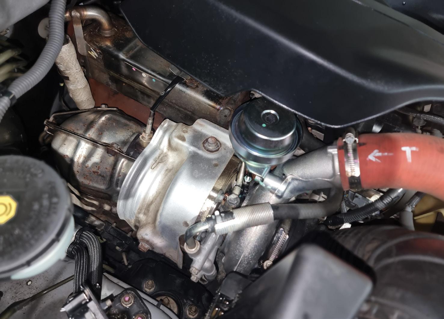
Confirmed the turbo vacuum solenoid had a solid 30 inches of mercury (inHg) supply and noted the vacuum supplied to turbo vacuum actuator at idle was 10inHG. The actuator would move when the engine was revved.
Disconnected the vacuum hose from the turbo actuator and road-tested the vehicle

again – found it was sluggish and would not overboost, so the turbo internal vanes were not stuck.
Back in the bay, I teed a vac gauge onto the turbo vacuum actuator. With someone blipping the throttle, I noticed the vacuum solenoid was altering its vacuum supply in line with the blips but occasionally the actual turbo actuator rod would hang.
A few times I caught the rod in a vacuum position from the blip yet I could physically disconnect the vac hose and it would take a second or two for the rod to return to rest. This made it obvious that the turbo vanes were sticking momentarily. We quoted a new turbo (pic 1).

With the turbo removed, you could feel something was binding inside the turbo and no amount of external lubrication or movement was able to release it (pic 2).
Fault description
The turbo’s internal vanes were sticking, causing overboost.
Fault solution
Replaced the turbo assembly.
Recommended time
Diagnostic time was one hour, taking into account preparation and research. Repair time was four hours, taking into account the location of parts and carrying out the repair to a tested outcome.
This is becoming a very common problem with the MHI turbo that Isuzu used for a few years on the engine, to the point we have heard stories of repeat failures within only a couple of years of a new genuine turbo being fitted.
This problem is a design issue with the MHI turbo. There are now conversion options from IHI turbo that prevent repeat failure and are worth exploring if your customer is keeping the car long-term.
Repair Solution provided by TaT Tech Team member Brendan Sorensen.

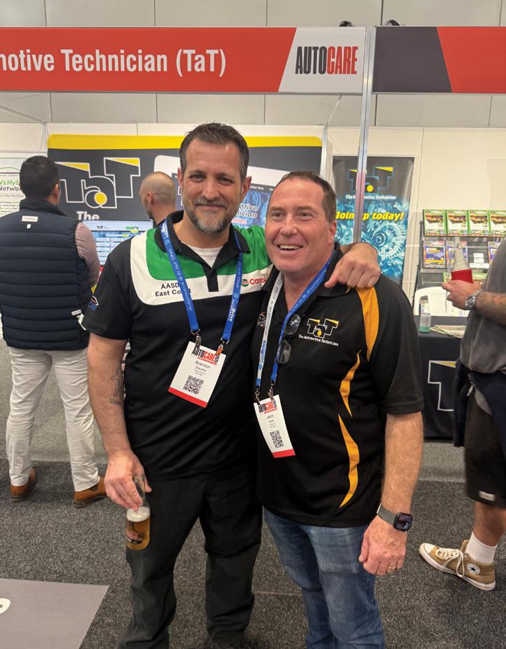
Autocare 2025 brought the Australian automotive industry together in Brisbane for two impactful days of training, innovation and connection.
Hosted by the Australian Automotive Aftermarket Association (AAAA), the event reaffirmed its status as the nation’s leading skills and training expo for automotive professionals.
With thousands of technicians and workshop owners in attendance, Autocare delivered a comprehensive program combining worldclass technical training, business education and a vibrant trade show.
The Workshop Management Program featured respected industry leaders and operators sharing real-world strategies to future-proof businesses.
Sessions explored artificial intelligence (AI) integration, managing staffing shortages, boosting productivity, electric vehicle (EV) servicing, marketing and leveraging the Motor Vehicle Information Scheme (MVIS) for better diagnostic outcomes.

The Technical Training Program brought together Australia’s finest trainers with leading experts from the US. Sessions covered advanced diagnostics, J2534 programming, network troubleshooting, EV and hybrid service, advanced driver-assist system (ADAS) calibration, diesel systems and oscilloscope essentials – ensuring technicians are equipped for today’s complex vehicles.
More than 120 leading brands took part in the bustling Autocare Trade Show, showcasing the latest in diagnostic tools,


workshop equipment, parts and service solutions.
The Product Showcase Stage, sponsored by Abrasive Stocks, added interactivity with live demos and new product launches.
ADAS Industry Code of Conduct launched
A major announcement at Autocare 2025 was the launch of the ADAS Industry Code of Conduct, developed by AAAA and the Automotive Repairers Council of Australia (ARCA).
The code provides practical guidance for workshops, windscreen, tyre and collision repairers on calibrating ADAS following
repairs. It includes step-by-step procedures, checklists and decision tools and is available via the AAAA website.
The Flying Spanners competition, sponsored by Supercheap Auto Trade, was a standout crowd favourite. Apprentice teams from around the country competed in highpressure, skills-based challenges that showcased the capabilities of the next generation of technicians.
A clear vision for the future
‘Autocare 2025 gave our industry a powerful moment to pause and look forward,’ said AAAA CEO Stuart Charity. ‘Whether it was

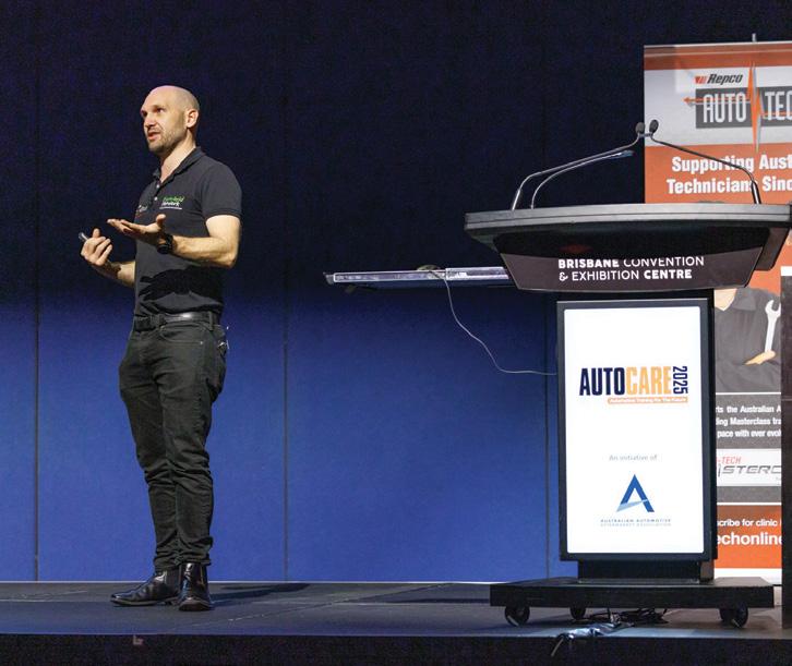
to strengthen their business or grow their personal career, attendees left empowered and future-ready.’
Autocare 2025 was a celebration of learning, innovation and the resilience of Australia’s automotive industry – and proof the future of vehicle service and repair is in great hands.
• Find out more at autocare.org.au

For aftermarket automotive professionals, staying ahead means offering solutions that meet the demands of tradies, families and anyone needing superior suspension.
This is where Airbag Man suspension systems can become a powerful asset for a workshop. Airbag Man offers a reliable, robust, and profitable avenue for enhancing clients’ vehicles. Its kits are designed for efficient installation and to maximise a workshop’s throughput and profitability. The kits are predominantly bolt-in with no drilling typically required, significantly reducing installation time and complexity.
Furthermore, the ability to retrofit new Airbag

Man products onto existing setups, often with the addition of simple spacers, means workshops can offer valuable upgrades without pushing clients towards a full suspension overhaul – a win-win for both your business and their budget.
Technical proficiency, simplified Installers often ask about leaf versus coil assist. Knowing the difference can help you recommend the best option.
Leaf-assist airbags, mounting between the chassis and leaf spring, are ideal for combatting sag under consistent heavy loads, a common issue for commercial vehicles and those towing large caravans. Coil-assist airbags, installed inside coil springs, offer precise load levelling and ride refinement, adaptable to OE or aftermarket coils.
Understanding these distinctions allows workshops to confidently advise clients and tailor solutions to their specific needs, whether it’s a tradie’s ute or a luxury SUV.
For clients whose load and road conditions are constantly changing, recommending an onboard air-control system is a no-brainer.
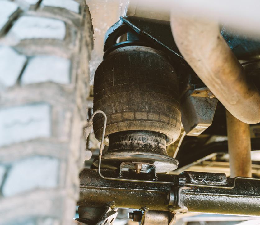
Airbag Man’s Firestone Wireless App system allows remote pressure adjustment for towing, off-road or daily driving across all kits. This adaptability adds premium value and client satisfaction.
Catering to every Australian lifestyle
The beauty of Airbag Man products lies in their versatility.
Whether your client lives for the hardcore off-road lifestyle or prefers the comfort of caravan-park travel, Airbag Man products are designed to provide tangible benefits. Full air suspension is ideal for off-roaders needing adjustable ride height, while caravan owners benefit from easy levelling and improved comfort.
Understanding these benefits can help a workshop market solutions that meet diverse needs.

Durability you can stand by
Reputation is everything in the aftermarket,. When a workshop installs Airbag Man, it is fitting products with a proven track record.
Airbag Man airbags are not merely designed for Australian conditions, they’ve been tried and tested in the most extreme environments, including the harsh Australian outback.
This extensive real-world validation, spanning thousands of miles with minimal reported issues and known cases of airbags performing strongly after 20-plus years, provides you with powerful selling points and peace of mind.
When you say, ‘Bag it with the best’ you’re not just echoing a slogan, you’re guaranteeing quality and reliability to your customers.
Staying ahead with EV and hybrid compatibility
As the Australian automotive landscape rapidly electrifies, forward-thinking workshops are adapting.
Airbag Man is already ahead of the curve, offering select coil-helper kits that are directly compatible with electric vehicles (EVs) and hybrids, addressing the specific weight and performance characteristics of these new platforms.
A prime example is its CR5180HP and CR5185HP kits, specifically engineered for the 2024-25 BYD Shark 6. By offering these solutions, workshops can position themselves as a leader in emerging automotive technologies, attracting a new segment of the market and future-proofing their business.
Stocking and installing Airbag Man suspension means offering robust, versatile solutions that can improve load carrying, comfort and control, equipping your aftermarket-auto business to thrive in the dynamic Australian market.
Partner with Airbag Man and help your clients confidently conquer any load or terrain.
• Find out more at airbagman.com.au or free call 1800 247 224.
– thanks Noel from NZ!
A 2017 Nissan Navara D23 with 135,000km on the clock was towed in after it stopped running about an hour into a drive. Once in the workshop, it would not crank but the battery tested fine.
A full scan of the vehicle revealed the engine ECU wasn’t being recognised – it also didn’t appear under OBDII. Plenty of CAN bus codes were stored and I was just about to start tracing wiring diagrams when I turned to TaT — as usual — to see if this was a known issue.
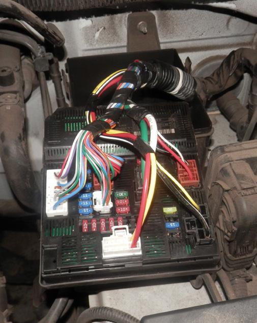
Sure enough, thanks to Noel Birchall from New Zealand and his case study NISNA161198, I checked the intelligent power distribution module (IPDM) located at the left-rear of the engine bay and found the 20A electronic concentrated control system (ECCS) fuse blown. I replaced the fuse, which promptly blew again. Next, I inspected the wiring loom at the right side behind the airbox and found a red wire had rubbed through and shorted against a bracket. Modified the bracket and repaired the wiring. After a full scan, all modules were now back online.
Diagnostic time for this job was 30 minutes and repair time 90 minutes.
Gary Homan
Nudgee Automotive Services NORTHGATE, QLD

There is no denying that modern vehicles are complex machines, a fact underscored every time a warning light appears on the dashboard accompanied by a fault code.
Yet as every technician knows, a fault code rarely provides an exact diagnosis. It certainly points us in the right direction but it won’t always tell us exactly what’s wrong –though that would be nice.
That is why we have been working hard to grow and develop the TaT Fault Code page, a tool that goes far beyond your standard fault-code definition. The page has been designed from the ground up to be useful to working technicians in the workshop and I believe it is growing into one of the most practical resources we offer to our members.
More than just a code and description
If you have ever seen a code such as P0046 you’ve probably also seen the description that comes with it, which would be something like, ‘Turbo/supercharger boost control solenoid circuit range/performance’. While this is helpful, it doesn’t clearly explain why the ECU set the code in the first place, leaving you wondering whether the fault lies with the turbo itself, the solenoid or something else entirely.
This is where the TaT Fault Code page goes deeper.
Each entry includes:
• A clear definition of the code.
• A list of possible causes to help you narrow down the likely faults.
• A detailed diagnostic assistant, giving a step-by-step guide to help you test and confirm the issue.
These sections are written in plain English and built to be practical. They are based on known fault patterns, real-world testing procedures and years of combined workshop experience. The aim is to give you a reliable guide for where to start, what to check and how to confirm the fix.
How it works
When you visit the Fault Code page, you will see a searchable table with six columns:
• Make: This shows the vehicle manufacturer if the code is specific to a particular brand.
• Code: The fault code itself (e.g. P0420).
• Sub code: Some manufacturers include an extra identifier or INF code, often called a sub code.
• Definition: A brief description of what the code means.
• Copy: A button that copies the code and description to your clipboard, ready to paste into job notes or a technical assistance request.
• Details: A small star icon that you click to open the pop-up window full of information on the code.
This page wasn’t built in a boardroom or based on what looks good in a brochure. It came from the workshop floor, conversations with members, feedback we receive through our technical assistance and the challenges we have faced when diagnosing modern vehicles.


The information is clear and written for people who turn spanners, not sit in suits.
We know that when dealing with an intermittent driveability issue or a difficult fault you do not have time to read through multiple pages of theory. You simply want to know what it means, what commonly causes it and what you can test to prove or disprove the diagnosis. And that is precisely what the TaT Fault Code page delivers.
The details column will contain either a yellow or green star.
Yellow star: Opens a pop-up with the fault code, definition and possible causes.
Green star: Includes everything from the yellow star, plus detailed diagnostic assistance information.
We’ve recently added a print button directly in the pop-up window, so you can now print the information to keep it on the job card or hand it to another tech on the floor.
You’ll often find a related technical video link at the bottom of the pop-up window. These might include practical repair walkthroughs, testing tips or examples of similar jobs.
As this was written, the database included more than 8000 fault codes and we are adding and updating more every day. These cover:
• P codes: Powertrain codes, including engine and transmission.
• C codes: Chassis codes.
• B codes: Body and electrical components.
• U codes: Communication and network faults between modules.
We are constantly adding, editing and updating our code library. However, whenever we come across a new or
interesting code through a member requests, Technical Assistance case or manufacturer bulletin, we research it, write it up and add it to the system.
The aim is to build the most relevant, workshop-friendly fault-code database available to the aftermarket.
Many members use the Fault Code page as a first step when a code pops up during a scan. Others come to it after trying a few things and hitting a wall. Some use it to write up reports for customers.
However you choose to use it, our goal is to make it quick, easy and effective. You do not need to be a diagnostics expert to understand the entries but if you are an expert you will appreciate that the information is sharp, structured and focused on real results.
What’s ahead?
We plan to connect even more parts of the TaT system in the future. That means linking fault codes directly to Repair Solutions
and Technical Assistance cases. The more integrated the system becomes, the faster you can move from scan tool to solution. We are also working on making the search smarter, so even if you are unsure of the exact code you can still find what you need by vehicle, symptom or system type.
At TaT, every feature we develop serves a clear purpose and the Fault Code page is no exception – it’s practical, precise and built to make your job easier.
So next you’re faced with a tricky fault code, jump onto the Fault Code page. The solution might be just one click away.
A quick update on the latest AI advancements we’ve made to the TaT website
Over the past 18 months we have been working on incorporating artificial intelligence (AI) into the TaT website.
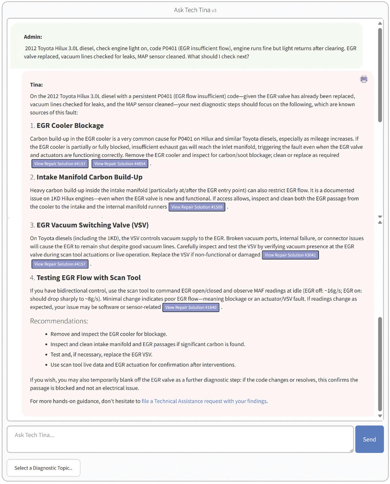
Tech Tina, our highly trained AI, now has access to several of our technical databases. By leveraging direct access to our databases, she is providing step-by-step diagnostic pathways and instant links to TaT Repair Solutions, exactly the support that busy technicians and workshop owners need.

Member feedback has been overwhelmingly positive, especially when it comes to how our AI empowers workshop staff to self-research and problem-solve.
For some workshops Tina is the answer to their ‘first five minutes’, when they can decide if a job is within their skillset or choose another option for their customer… removing the potential for
Look to the picture on this page for an example of what Tech Tina can do – note the number of times a TaT resource link
If you haven’t already tried Tina out, we encourage you to do so. We believe she’s a real gamechanger and is changing members approach vehicle diagnostics and searching for information.

Engineers have devised ingenious circuits to convert direct current (DC) into the alternating current (AC) used to power three-phase AC motors for traction (referred to as the ‘load’), thereby creating full electric vehicles (FEVs).
However, this is contrary to the familiar alternator used in an internal combustion engine (ICE) vehicle, where alternators generate AC which is then rectified and regulated to DC – only to power the vehicle’s systems (collectively referred to as the ‘load’).
While both methods aim to power the load, for the purposes of this article we will focus on how they compare when calculating electrical power. In a DC system, calculating power is straightforward:
• Power = voltage × current (Ohm’s law).
However, power calculation in an AC system involves more nuance, particularly due to different voltage measurement methods such as root mean square (RMS) and peak-to-peak voltages. For example:
• A household general-purpose outlet (GPO) is rated at 245V RMS.
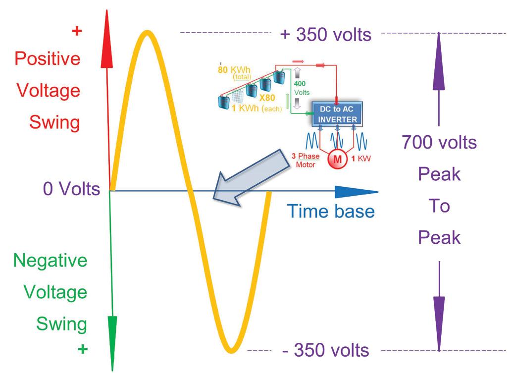
• An inverter in an FEV may output an AC voltage up to 700V peakto-peak (figure 1 – yellow).
When diagnosing an FEV, understanding the difference between RMS voltages (measured with a digital multimeter [DMM]) and peak-to-peak voltages (viewed on an oscilloscope) is crucial.
In this article, we will explore the following from a mechanic’s point of view (MPOV):
1. How FEVs convert battery-supplied DC into usable AC via an inverter.
2. The anatomy of a sine wave (as generated by an alternator).
3. How power calculation differs between DC and AC systems.
In an FEV, AC is generated electronically from the DC battery using inverters, unlike an ICE vehicle where alternators produce AC directly.
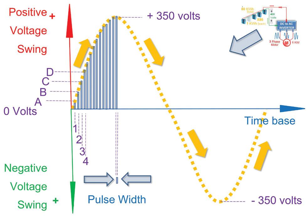

Without diving into academic debates, let’s consider a simplified view of one common method.
Imagine we want to mimic a 240V RMS sine wave (figure 2 – yellow).
The inverter:
• Pulses voltage at incremental levels based on a programmed algorithm:
- Pulse A at time 1 (figure 2 – purple A-1).
- Pulse B at time 2 (slightly higher) (figure 2 – purple B-2).
- And so on (C, D, etc).
• Until the voltage reaches a peak (about 350V).
• It then mirrors the sequence in reverse, tracing a sinusoidal envelope through carefully timed voltage pulses (figure 2 – yellow arrows).
How ingenious is this technique? While known as sinusoidal pulse width modulation (SPWM), it effectively builds a sine wave from discrete DC pulses, thereby emulating the shape of an AC signal suitable for powering the vehicle’s electric motor.
How do the voltage (amplitude, peak-to-peak) and frequency (how often the peaks and troughs occur in one second) affect power delivered to the load? Well, much more on that later. For now, let’s examine the anatomy of a sine wave.
Characteristics of an AC waveform:
A mechanic’s point of view
Let’s start with something familiar – the alternator.
From a mechanic’s perspective, when an alternator’s pulley begins spinning – say, at idle speed (figure 3 – grey 1) – and exciter field voltage is applied:
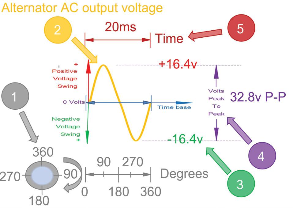
• The internal windings generate AC voltage (figure 3 – yellow trace sine wave).
• Voltage swings from 16.4V peak (figure 3 – yellow 2) to minus 16.4V trough (figure 3 – green 3).
• Creating a 32.8V peak-to-peak waveform (figure 3 – purple 4).
• With one complete cycle occurring every 20 milliseconds (ms) (figure 3 – brown 5).
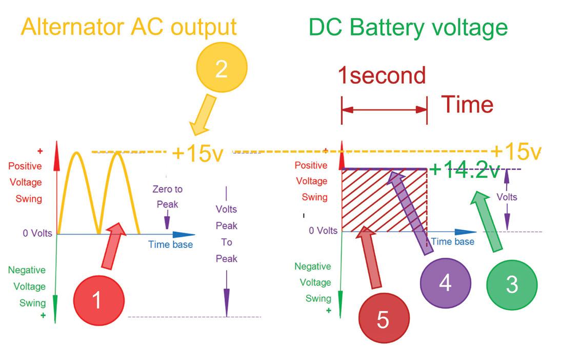
Full-wave bridge rectification: Converting AC to DC
All automotive alternators employ a full-bridge rectifier (four diodes). This configuration:
• Flips the negative half of the AC waveform to positive (figure 4 –red 1).
• Produces a rectified output of about 15V after accounting for typical diode drops (~1.4V total, figure 4 – yellow 2).
• A voltage regulator then stabilises the output at around 14.2V (figure 4 – green 3).
• The vehicle’s battery further smooths voltage fluctuations (figure 4 – purple DC line 4).
The power delivered to a resistive load is calculated as:
• Power = voltage (DC) × current.
The energy consumed over time (joules) corresponds to the area under the voltage/time graph (figure 4 – brown 5).
For example, a 1W load uses one joule of energy every second (see TaT 102, page 11).
Comparing AC power: The role of RMS
When calculating power in AC systems like those in FEVs, we use the RMS value – which represents the effective voltage – because voltage continually alternates.
Determining the area under a sine-wave curve involves complex mathematics (figure 5 – red 1 and purple 2). However, engineers often use a practical approximation (reference 1):
• Vrms = Vzero-to-peak × 0.707.
Applying this:
• Vrms = 350V × 0.707 = 247.5V (figure 5 – red 1 and green 4).
Therefore:
• A 245V RMS household GPO voltage corresponds approximately to…
• … 350V zero-to-peak voltage…
• … and 700V peak-to-peak voltage.
Safety note: This 700V swing is very real – and extremely hazardous if accidental contact occurs, emphasising the importance of proper safety protocols.
In essence, RMS provides a way to equate the power of an AC to that of an equivalent DC source (reference 2).

Comparing areas under sinusoidal waveform
Let’s revert back to the familiar alternator and GPO.
• An alternator’s AC output (~33V peak-to-peak, figure 3 – yellow).
• And a household GPO (~700V peak-to-peak, figure 1 – yellow).
• Share similar wave shapes but have drastically different RMS voltages. From the MPOV, the waveforms appear the same yet they differ significantly in the effective power (V × I) delivered to the load, whether it’s an FEV traction motor or ICE electrical and/or electronic essentials.
In summary
When diagnosing an FEV, it is essential to understand:
• A DMM measures the RMS value on the AC range.
• An oscilloscope displays the peak-to-peak voltage directly. Though AC voltage waveforms generated by ICE vehicle alternators (~32.8V peak-to-peak) and household GPOs (~700V peak-to-peak) are similar in shape, the RMS values must first be considered before calculating the power to a load.
For DC systems:
• Power = voltage × current.
For AC systems:
• Power = Vrms × current.
• Where Vrms = Vzero-to-peak × 0.707.
Finally, an inverter in an FEV reconstructs sinusoidal waveforms by pulsing DC voltages at precisely timed intervals, effectively emulating the shape of an AC signal suitable for powering the vehicle’s electric motor.
Until our next instalment:
What happens when the pulse width (PW) in figure 5 is increased?
Hint: Will it alter the voltage, the frequency or both?
These articles aim to explain the fundamentals of EV systems in an accessible way.
However, contact with high voltage is lethal.
If you plan to measure or work on high-voltage systems:
• Always use appropriate tools (CAT IV-rated DMMs, insulated gloves, etc).
• Strictly follow de-powering procedures.
• Only work after completing certified high-voltage training.
For more, refer to TaT EV training resources.
References
1. allaboutcircuits.com/tools/peak-to-peak-voltage-calculator/ 2. allaboutcircuits.com/tools/peak-voltage-calculator/

Jason Smith
Intermittent faults with vehicles have been a constant challenge throughout my entire career; I’m sure many other technicians can relate to this.
We’ve all had cars booked in with potential intermittent faults or driveability issues, then when you go to road-test the vehicle the fault just isn’t present. This is where experience and diagnostic equipment can become very useful.
Let’s focus here on experience and then diagnostic equipment. So a car comes in with a potential intermittent fault. You road-test it and, sure enough, it doesn’t fault – what do you do? Load that parts cannon and just start swapping parts? Or roll the fictional diagnostic dice – not a great idea, either.
From my experience, this is what far too many mechanics do far too many times. Sometimes they can get lucky and stumble across the fault but eventually they can and do get caught.
In fairness to them, sometimes the situation can be exacerbated by an impatient customer who just wants their car repaired. This may lead to the mechanic swapping parts and not following a correct or regimented diagnostic path.
Add to this the reality of installing poor quality or sub-standard aftermarket parts that, when fitted, create other problems, leading not only to the original fault but other faults that can take a technician now working on the vehicle to new levels of confusion and frustration.
My strong opinion is don’t be pushed into anything by anyone, whether it’s a customer or workshop supervisor or whoever.
Let’s call it the way it is – if you were to just go ahead and replace parts on just a hunch, the cost would add up very quickly, and if this didn’t fix the problem with the vehicle, the customer would not be happy.
That’s why, in my opinion, you should not take the job any further unless you see, feel or hear the problem. Wait for the fault to develop and become reliably repeatable so you can accurately diagnose it in a professional manner.
Equally, this doesn’t mean you don’t go ahead and perform some basic visual and physical inspections. This is where diagnostic equipment may come in very useful when diagnosing intermittent faults. A smart test of the battery and charging system is a good place to start. A full diagnostic scan of all modules fitted to the vehicle may be the next step.
Remember, the customer thinks you plug a magic computer thing into their car that tells you exactly what’s wrong with the vehicle, so it’s important to carefully manage expectations while also keeping a positive attitude. Don’t be a negative Nelly – show confidence in the diagnostic processes you should already have in place.
This will make the customer comfortable you are the right person to fix the fault and also show them any diagnostic fee you are charging is value for money.
If there are DTCs, capture or record them and check for freezeframe data; this may help identify what load or conditions were present when the fault occurred. A simple explanation of freezeframe data that you can share with customers is the vehicle’s ECU, powertrain control module (PCM) or other control module taking a ‘selfie’ when the fault occurred – this could be helpful when trying to identify intermittent faults.

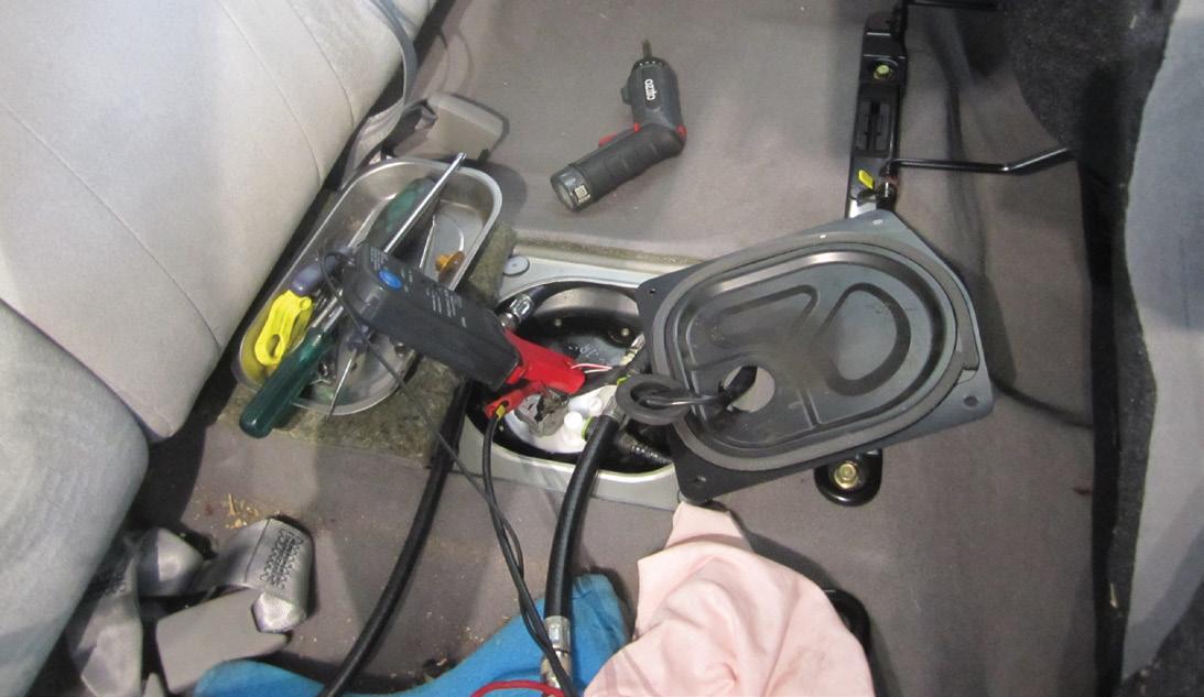

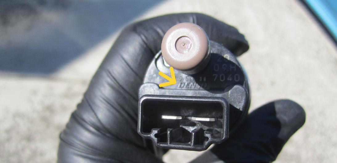
An oscilloscope could also be used to check for abnormal waveforms in sensors or actuators, stepper motors, pumps (like the case study below) or ignition components.
Don’t forget the humble smoke machine because even a quick check can be useful. After all, it should be quickly and readily available for diagnosis. My smoke machine has led me to cracked or broken hoses and pipes that have been the cause of intermittent problems many times.
At this point, evidence-based decisions should always be the goal. If the car won’t fault, it may be time to stop and reevaluate. Consider waiting for the fault to develop, when it can be reliably repeatable, so it can be clearly and confidently identified, then repaired. Now let’s dive into a recent case study involving a car with an intermittent problem. The customer’s accurate description of when the fault occurred, teamed with my experience and the use of a piece of diagnostic equipment (Pico scope), led me to identifying the faulty/dying part and quickly moving on to repair the vehicle.
The car:
Ford KQ Laser, 02/2002, 1.6-litre ZM engine, 165,000km on the clock (pic 1).
The complaint:
The vehicle had stopped and now wouldn’t start. It had been towed into the workshop.
Diagnostic sequence:
Detailed discussion with the owner revealed the circumstances when the fault occurred. He said he was driving along and went to pull up at a set of traffic lights when the engine lost power, ran rough at idle, then just stopped.
The customer said he went to restart the engine and while it did start, it ran rough. He noticed the engine wouldn’t rev very high, then it stopped. It would then crank but not restart, so the car was towed in. Any technician has probably heard this scenario many times.
I went to the vehicle and the engine started straight up. I revved the engine and it seemed to run normally. Next, I performed a short road test, even driving up a reasonably-sized hill, and the car seemed to be running and performing OK.
Next came some basic tests and checks: I checked fluid levels, visually checked hoses and fittings, smart tested the battery and charging system – all appeared OK.
I made phone call to the owner telling him the car was running; of course, he was now frustrated. He did say the car had been sitting for about three weeks before I’d got to see it.
Going off the customer’s accurate description of the fault events, I was thinking the vehicle possibly had a failing in-tank fuel pump. I very carefully communicated this to the owner, at which point he reminded me I’d done a pre-purchase inspection when he purchased the car roughly three years ago and had discovered some documents that suggested the vehicle had recently had a new in-tank fuel pump fitted. At the time I’d mentioned that some of the details on the document had implied a lesser brand fuel pump had been fitted.
Moving on, I put forward a plan to perform a scope test of the in-tank fuel pump – he agreed. I removed the back seat from the vehicle to expose and then remove the inspection cover, then connected a current clamp to the fuel pump wiring – polarity sensitive of course (pic 2). Next, I started the engine and, to my surprise, the answer was staring me right in the face – the waveform (pic 3) clearly showed a problem.
The fuel-pump waveform had large peaks only with no troughs, as well as a very high amp draw (yellow trace) and bad hash on the voltage line (green trace). When I added some rulers to the waveform using the Pico software, I calculated the fuel pump to be only rotating at around 250RPM.
That’s very low and something I’d never seen before on a fuel pump that was still running an engine. Additionally, with the inspection cover removed, the in-tank fuel pump could clearly be heard growling – not a happy humming or buzzing noise like you would expect to hear. In short, the fuel pump was clearly the problem.
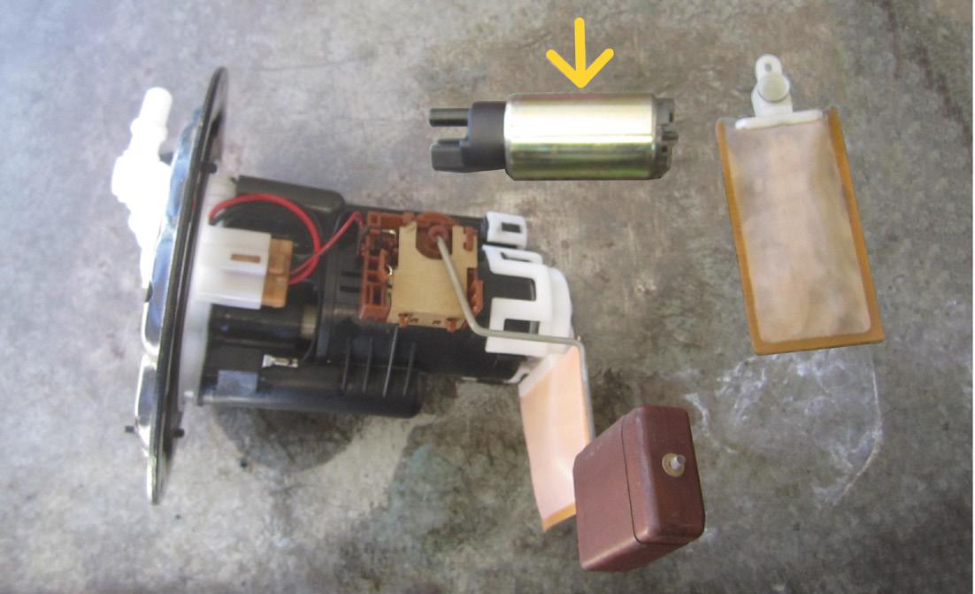
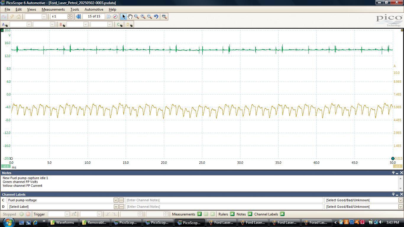

Removed the old fuel pump and, as suspected, it was a cheap, noname aftermarket pump and it had only lasted around three years. Sourced and installed a quality OE Denso pump (pic 4). Note pic 5, which shows the old, faulty pump on the bench – notice it still looks like new.
Connected the fuel-system analyser to the main fuel line to accurately test the fuel pressure and flow, then started the engine. The scope waveform showed nice oscillations (yellow trace) and we now had an approximate pump speed of 8600RPM and an average amp draw of approximately 5A (pic 6). The pressure and flow readings were to manufacturer specifications (pic 7).
Road-tested the vehicle, then returned it to the owner. I contacted him one week later as a courtesy and he confirmed the vehicle was running well and had no further problems.
In closing:
If an intermittent fault with a vehicle isn’t reliably repeatable, do your basic tests and checks. Then stop, communicate with the owner and consider waiting until the fault can be accurately diagnosed with data-based findings. That way you can carry out a confident repair or replacement.
Happy diagnosing!

Invicta Lithium is expanding its high-performance power-solutions portfolio with the launch of its Pure Power Inverter range, available from July.
The series begins with a 2000W model, with 1000W and 3000W versions to follow.
Designed to convert 12V DC from Invicta Lithium Batteries into stable 240V AC, these inverters are ideal for powering sensitive electronics and critical equipment –from refrigeration units to portable diagnostic tools – ensuring reliability in mobile and remote applications.
Invicta Marketing Manager Callen Price emphasised the rigorous development protocol.
‘Our design philosophy for these inverters prioritised comprehensive functionality and robust performance,’ said Price. Each unit features:
• Pure sine-wave technology.
• Automatic transfer switch (ATS).
• Residual current device (RCD) protection.
• Full Australian certification.
Invicta’s sine pulse-width modulation (SPWM) algorithm and LC resonant modulation are designed to deliver a clean, low total harmonic distortion (THD) sine-wave output, ensuring safe and efficient operation of connected devices and maintaining power quality across all loads.
An integrated LED display and detachable wired remote provide realtime system data, including voltage, current, power use and error
A 2018 Ford Ranger
PX2 with 123,000km on the clock was brought in after the customer lost all drive in all gears.
The vehicle would still select reverse and showed correct gear selection on the dashboard but had no movement.
Scanned for fault codes – none were present.
Disconnected the oil lines from the transmission cooler to check for fluid flow but the transmission wasn’t pumping any fluid.
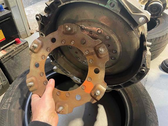
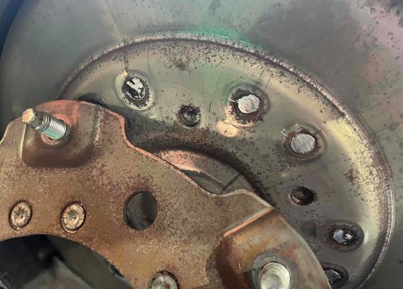
Removed the transmission and found the stud plate on the torque converter had broken its welds and completely snapped. Fitting a new torque converter to the transmission and reassembling solved the problem.
Diagnostic time for this job was 90 minutes hours and repair time eight hours.
Winston Hannaway Winnie’s Auto Repair RONGOTAI, NEW ZEALAND

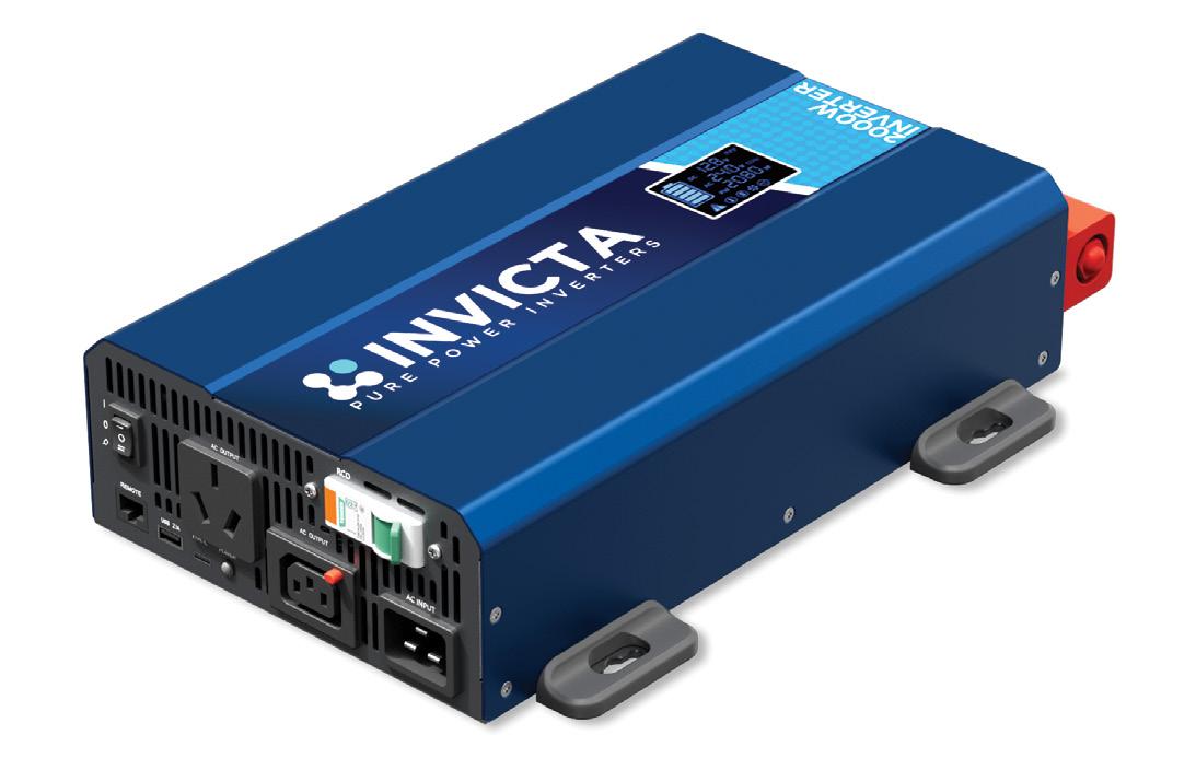
Standard IEC and GPO sockets comply with Australian 240V AC requirements. Safety features include residual current device (RCD) earth-leakage protection, along with safeguards against overload, overheating, short-circuit and low voltage – extending the life of both the inverter and connected equipment.
All models undergo rigorous testing and meet Australian compliance standards. Each unit also includes a Kering remote for convenient power control and battery management.
The Invicta Pure Power range is engineered for professionals who require dependable AC power in demanding environments, whether it’s for vehicle fit-outs, mobile service units or off-grid installations.
• Pre-orders are now open through Sealed Performance Batteries. To find out more, call 1300 001 772, email sales@spb.net.au or go to spb.net.au

Geoff Mutton Business Resources
Maintaining profitability and positive cashflow during the cost-of-living crisis
Rising
For mechanical workshops, staying cashflow positive is more crucial than ever – not only for survival but ongoing success. While car counts and customer demand may seem steady, profitability can quickly erode if strong controls are not in place. Here are some strategies to ensure your workshop remains financially resilient.
Review your pricing
Official inflation figures might appear to be easing but key workshop costs – especially energy and insurance – continue to rise. It is essential to conduct regular price reviews to keep pace with your input costs. Small, frequent price increases are much more palatable to customers than large, abrupt hikes every couple of years.
Proactively re-engage overdue customers
Customers are naturally inclined to defer maintenance and repairs when budgets are tight. However, many will appreciate a courteous reminder when a service or repair is well overdue. Harness your database to send targeted, friendly reminders at regular intervals – sometimes it’s the second or third contact that prompts action, especially as household finances improve.
A simple follow-up such as a personalised text message or phone call a few months after the initial reminder can boost workshop bookings and retain customers long-term.
Cashflow health starts with monitoring your business numbers. Set time aside every month to review sales, gross margin, technician productivity and the average sale value. These key performance indicators (KPIs) offer early warning if something’s not right and give you the data to act proactively.
• For more assistance in this area, check out our ‘Understanding your numbers’ webinar at tat.net.au/scandata/classes/ webinar/main_template.php. It will help deepen your understanding of profit-and-loss statements, margin management and technician output targets.
Minimise mistakes and comebacks
Mistakes and vehicle comebacks are always costly but in tougher economic conditions the impact on cashflow and reputation can be especially severe. Every rework job is time, labour and parts you cannot invoice – directly eating into your bottom line.
Now, more than ever, it’s vital to review your workshop processes and ensure robust quality controls are in place. Remind your team regularly that the quality of their workmanship is non-negotiable. Foster a mindset that values quality over quantity.


Don’t offer credit to retail customers

The era of ‘put it on the tab’ ended long ago for petrol stations and supermarkets and your workshop should be no different. Credit should only be considered for reputable trade customers – those who manage sizeable fleets, have solid payment histories and require periodic consolidated invoicing. Retail customers (the classic mum-anddad clients) and tradespeople with a single ute should only be offered pay-on-pick-up terms.
Maintaining strict payment terms will preserve your cashflow and prevent mounting bad debts. If you must offer credit, ensure formal agreements are in place and strictly monitor outstanding balances.
Ensure payment on vehicle pick-up
The most common reason retail customers end up with outstanding invoices is the workshop not having the bill ready at collection time. If your team ends up saying, ‘We’ll email you the invoice later’, you are opening the door to delayed payments and unnecessary admin headaches.
It’s essential to make invoicing a priority. Have invoices prepared and ready for the customer’s arrival so payment can be collected – EFTPOS, credit card or even cash – before handing over the keys.
If your current workflow can’t reliably produce same-day invoices, it’s time to review your management system and processes. Investing in modern workshop software to automate and streamline invoicing pays for itself many times over in reduced admin work and tighter cashflow controls.
Stay on top of debtor collection
Chasing outstanding accounts is nobody’s favourite task but letting it slide only compounds the pain when bills come due. For workshops still extending credit to select trade customers, debtor collection must be a regular, planned activity. Set aside time each week to review an accounts receivable report
When following up, be firm, fair and friendly, stick to facts, keep emotions out and record every conversation with names, dates and details of promises made. A routine, business-like approach helps maintain good relationships and sets clear expectations for payment.
Having formal, well-communicated credit policies from the outset can make these conversations easier and less awkward for all parties.
Offer finance solutions, not workshop credit
It’s easy for business owners and frontoffice staff to get emotionally involved when a customer cannot afford a repair outright. While the intention to help is admirable, extending workshop credit frequently leads to delayed payment, bad debts and unnecessary stress.
A better solution is partnering with a reputable automotive finance provider. This allows customers to access external finance for repairs, shifting risk away from the workshop. If the customer is unable to obtain finance, that’s a sign they are already heavily burdened and at high risk of default.
Remember, finance solutions do come with fees, so review providers carefully and only offer these options where it makes commercial sense.
It’s good business practice to regular review expenses and shop around for essential services such as electricity and insurance. Look for areas where you can negotiate, bundle or switch suppliers for better rates – every dollar saved flows straight to your bottom line.
inventory holding
Inventory ties up cash and takes up storage space. Tighten your inventory-management practices and review upcoming jobs at least 24 hours in advance. Pre-ordering required parts reduces the need to carry high levels of stock and limits wastage from slowmoving inventory.
Long-standing supplier relationships are valuable but that does not mean you can’t ask for better pricing or payment terms. Often, simply asking or comparing
alternative options will prompt a review. In the current climate, suppliers are keen to hold onto reliable business and many are open to negotiation.
Positive cashflow is the lifeblood of every successful mechanical workshop, particularly now. By consistently applying these strategies, workshops can not only weather the cost-of-living crisis but emerge more efficient and resilient. Financial discipline, process improvement and regular customer engagement are your keys to sustainability.


If you stand still long enough the entire world will pass by – or so the saying goes.
With that in mind, here’s a topic I wrote about more than two years ago. Back then it was an Audi A3 with a very strange running issue that lasted for several minutes before returning to a degree of normality, then repeating itself each time from cold.
This time our guest was a SEAT Leon FR, which by coincidence utilises the same MQB platform and TFSI 888 1.8-litre engine as the Audi (pic 1). However, rather than just repeat myself from the previous topic, I’ll focus on how good – and dare I say, bad – decisions are easily made.
There has been a lot of media focus on artificial intelligence (AI) – arguably too much; people are starting to believe it is the natural way forward. Speaking as a technician, I want accurate data, leaving my evaluation to systems knowledge and skilful interpretation. Once we submit to computer-generated decisions, without the need or inclination to challenge, we become zombies. After all, that is exactly what serially generated DTCs are.
Do not judge me just yet. I want computers to assist, not dictate. A good technician has to process and reason through challenges. The public already believes that diagnosing faults is simply a matter of connecting a serial tool and Googling the solution. Then order parts on eBay!
Which brings me to my first point: just because you have experienced a similar fault, never proceed on that assumption. Follow a logical process, considering all essential data and symptoms. How many times has a customer walked in and said, ‘You must know what is wrong from your experience?’. To which I always reply, ‘It is my experience that prevents me from guessing!’.
Our SEAT had an unknown history, with all the usual giveaways of performance modifications. The only stored faults were a negative fuel-trim value of 30 per cent and random P300 codes. So too much fuel and wet-plug syndrome, I suspected.
I wanted to know if the computer was attempting to correct the issue or responsible for it. The


powertrain control module (PCM) has a primary responsibility to respond to sensor values, provided they fall within the look-up table values. So was it rich or did it think it was rich?
Collating live data values is a perfect, nonintrusive way to check critical PCM sensor inputs. After all, the problem could be mechanical or hydraulic (fuel delivery). Negative temperature coefficient (NTC) sensor values were correct from cold through to hot – 3V > 1V. Manifold absolute pressure (MAP) sensor readings were reasonable from cold and excellent halfway through the warm-up phase: 300 millibar (mbar)/20 inches of mercury (inHg). Accelerator-pedal position (APP) values were normal for a closed throttle position. The wideband air/fuel sensor bank #1 (B1)/ sensor #1 (S1) was showing a 50 milliamp (mA) negative deviation, returning to zero when hot, suggesting an excess-fuelling condition. So our lambda sensor was active and appeared to be acting correctly to the cold fuelling problem. It’s worth noting here you should not forget to check B1/S1 condition; however, these can take a while to heat up and come online.
The scope image (pic 2) shows it is possible to check wideband sensors for both:
• Current (black): Negative transition = rich, positive transition = excess air, returning to zero current = lambda 1.
• Voltage (blue): Nominal lambda 1 value 2.2-2.8V against MAP input or, as in this case, digital Amm.
The big issue I had was the direct-injection rail pressure was much too low and seemed to be reducing gradually from a base value of 152 bar as the engine warmed up:
• Theoretical base value: 152 bar, dropping gradually through 90/60/41 bar.
This is where systems knowledge is essential. The 888 MQB platform uses two separate fuel-delivery systems, working in harmony but separately.
From cold, the high-pressure direct injection provides fuelling up to a predetermined temperature value, approximately 45°C. Then the PCM switches over to port injection at approximately 4.5-5 bar, controlled directly from the in-tank pump module.
Once the switchover had taken place, the SEAT’s engine ran well. If you listen carefully, you can hear the changeover take place.

Interestingly, at this moment, I noted the high-pressure system returned to the correct pressure of 152 bar. This is correct should sudden high load be requested via the APP sensor. So we could assume there was no internal fuel pressure drop.
A simple yet valuable test for internal pressure drop is to snap open the throttle, kill the ignition switch at peak RPM, then –when the engine is stopped – return the ignition feed and note the high pressure, which should hold over a considerable time.
It is possible to check low and high-pressure decay with a gauge and digital multimeter (DMM) (pic 3).
The engine runs on port injection for most of its speed/load range, reserving the high-pressure direct injection for full load and instant throttledemand occasions. So our problem was confined to control of the high-pressure system, not a hydraulic fault.
From cold, the high pressure dropped incrementally under PCM control as both specified and actual values matched. What we had here was fuel entering the cylinders outside of normal PCM control. The PCM was reducing the delivery pressure, attempting to correct the fault, reacting directly to B1/S1’s rich-signal output.
The next important acknowledgement here was the PCM was listening. Based on this assessment and previous experience, the direct injectors were removed. The bench test – with the help of my good friend Phil Ellison at ASNU – confirmed excessive open pintle flow rates.
OEM injectors were fitted, complemented by new spark plugs and the oil and filter were replaced. It’s worth noting there is no serviceable fuel filter on this platform.
I came across some interesting information regarding injector O-ring identification based on colour. I cannot confirm the accuracy of the data but it starts the ball rolling:
• Black = standard range, low temperature, not suited for bioethanol fuel.
• Brown = high resistance to extreme temperature, turbo, compressed natural gas (CNG).
• Green = typical use gasoline fuel, good elasticity.
• Blue = high resistance to temperature, chemicals, ethanol.
To close the topic, high pressures were restored to 152 bar from cold, with actual and specified values matching. A full system readaptation was conducted, including the lowpressure (LP) priming pump.
