


If the ground source heat collector (the loop) in a ground source heating or cooling system, does not work as designed, then the whole system can be compromised. The loop may leak contaminating fluids into the environment and restrictions in the flow, of the heat transfer fluid, will affect the efficiency of the entire system. Envirohire Ltd have developed a system for the testing of the loop at the point of installation, and before commissioning, to confirm that the loop is fit for use. The loop assessment involves a pressure test for integrity and flow testing for heat transfer fluid circulation in about 2 hours. On some projects the building is constructed on top of the borefield. In these cases rectification of defects is impossible, and it is essential that the quality of the loop is confirmed before construction work begins.
1.1 The loop in the ground is an essential component of a ground source system, but it is very often overlooked with regard to the quality of the final installation.
1.2 A Formula 1 car is the epitome of automative engineering. Every component, engine, kinetic energy recovery system, gearbox, chassis, aerodynamics, braking system are optimised. Driven by a superstar and costing over £13M ($16M), it is useless unless the tyres, which is the only point of contact with the ground, can transfer energy efficiently. It is obvious what is wrong with the image opposite.
1.3 A defective tyre can be changed on a Formula 1 car in around 2 seconds. Rectification of a defective loop in a ground source heating system is not so straightforward.
1.4 A Formula 1 tyre can have an effective life of as little as 15 laps of a circuit. In several places, including the UK and New York, ground source heating and cooling systems are being installed in confined areas and the building is then constructed on top of the borefield. The building should last for 200 – 300 years. It would seem sensible to ensure that the loop is fit for use before you construct a building on top of it.
1.5 So what do we need to confirm before we consider that the loop is suitable for commissioning, even if you don’t intend to build on top of it?
Quite simply:-
i) Does it leak?
ii) Does the fluid flow through the pipework as required by the design?


2.1 The loop is made from polyethylene (PE), which is highly durable, and could have a working life of hundreds of years. The pressure testing of PE, however, is not straightforward as the material is subject to visco elastic stress which means it expands when pressurised. This phenomenon, which is also referred to as ‘creep’, creates issues during pressure testing as variations in the pipe diameter will affect the accuracy of pressure readings.
2.2 In Europe there is a specific test standard for PE pipework which has been used in the water supply industry for 25 years, BS EN 805:2000[1], which takes into consideration variations due to creep.
2.3 There are a number of test methods contained in BS EN 805:2000 to choose from. One involves a ‘pressure drop’ test. After flushing the loop for 10 minutes 1 , the loop is brought up to the test pressure 2 . The test pressure is then maintained by intermittent pumping for a period of 10 minutes. 3 . The loop is then allowed to ‘relax’ for 1 hour 4 , followed by a rapid reduction in pressure of 10% 5 . Due to creep the loop pressure rebounds 6 and the loop pressure is then measured for at least 30 minutes 7 . If the pressure does not drop by more than 0.1bar (1.47psi) then the loop is considered to be suitable for use. If there is any doubt over the test result, then the assessment period can be continued for a further 60 minutes. The pipework is considered to be intact if the pressure does not drop by more than 0.25 bar (3.7psi) over the 90-minute extended assessment period.
2.4 Any test regime must be safe, reliable, consistent and repeatable; with results that accurately reflect the parameters under investigation. The pressure drop test involves a series of steps which cannot be undertaken manually with any degree of confidence. Below is an extract from a current UK guidance document[2] which indicates the type of apparatus recommended for use and also the system for recording results. There is no protection for operators should pressurised pipework fail during testing.
Flow & Pressure Testing Pressue in [bars]
Fig 2.3. Pressure profile & time of ‘Pressure Drop Test’ in BS EN 805:2000.
Typical simple pressure test set up
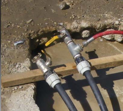

A stop watch, pencil and paper!
Fig 2.4. Example guidance on pressure & flow testing of loops

2.5 Pressure testing is considered by the UK Health & Safety Executive (HSE) to be a ‘High-Risk’ activity in their Guidance Note GS4 (Fourth Edition), ‘Safety Requirements for Pressure Testing’[3]. The document contains a reference in the HSE Research Report 168/1998[4] which states that, “It is difficult to think of any pressure test that will need no protection at all, although in a few cases it may be quite minimal.”
2.6 HSE Guidance Note GS4 recommends that any exposed pipework, being pressure tested for the first time, should be enclosed by 3mm mild steel plate as a minimum for operator protection.
2.7 The flow rate of thermal transfer fluid in the loop will be impeded if the loop contains restrictions due to debris or because the pipework is kinked. The performance of the loop can be evaluated by comparing the flow between the feed and return legs of the loop. Ideally the flow should be tested in both directions as there has been experience of debris in the loop only impeding flow in one direction.
2.8 Results obtained during loop testing can be adversely affected by external temperatures, both hot and cold. As the PE pipe is black, direct sunlight in particular can have a significant effect on the accuracy of results.
3.1 In the UK, on the 2nd October 2023, closed loop systems became subject to control under the Environmental Permitting Regulations 2016, in England, through Statutory Instrument No. 651 ‘The Environmental Permitting (England and Wales) (Amendment) (England) Regulations 2023 No.651’[5].
3.2 The statutory instrument brought closed loop installations into environmental legislation, and this required loops to have an environmental permit. The installation could, however, be exempt from permitting if the installation complied with binding rules which included complying with a number of published standards.
3.3 The published standards named in SI 651 includes BS EN 805:2000 as well as the following standards produced by the Ground Source Heat Pump Association (GSHPA):-
i) The Closed-loop Vertical Borehole Design, Installation and Materials Standards, issue 1.0, dated 2020. (VBS) [6] .
ii) The Shallow Ground Source Standard, Version 2, dated January 2018 (SGSS)[7].
iii) The Thermal Pile Design, Installation and Materials Standards, Version 2, dated September 2018. (TPS)[8].
3.4 All of the GSHPA standards include the BS EN 805:2000 drop test for assessing loop integrity and flow test using potable water. Clean water is not always available on a working site and the introduction of solids and microorganisms into the loop, during testing, can cause issues with loop performance and durability.
3.5 In the GSHPA standards the flow test requires the loop to be tested at the design flow rate. The standards specifically state that the loop should be tested in both directions without disconnecting the pipework.
3.6 In the USA the International Ground Source Heat Pumps Association (IGSHPA) produced the publication ‘Closed – Loop/Geothermal Heat Pump Systems, Design and Installation Standards’[9] in 2017, which included in Section 1, details of ‘Flushing, Purging, Pressure and Flow Testing.’ The document is due to be superseded in 2025 by a Bi-National standard jointly produced by the IGSHPA, American

National Standards Institute (ANSI) and Canadian Standards Association (CSA) to also cover Canada. The standard will be titled as ‘ANSI/CSA/IGSHPA C448’.
3.7 The current 2017 IGSHPA standard requires that the loop is tested for pressure in accordance with ASTM F2164[10], a standard produced by the American Society for Testing and Materials.
3.8 As with BS EN 805:2000, the ASTM F2164 standard involves monitoring the pressure of the loop in response to a controlled drop in pressure. The loop is pressurised to 1.5 times the design pressure, and maintained, for a period of 4 hours. The pressure is then dropped by 10psi and the rebound pressure measured for 1 hour. If the pressure does not fall by more than 5% of the original test pressure, then the loop is considered to be intact.
3.9 Flow testing in the 2017 IGSHPA standard involves comparing the feed and return loop flow rates for comparison with theoretical values. A reduction in flow rate which exceed 10% of the calculated values are indicative of a blockage and require identification and rectification.
4. Automated Loop Testing System
4.1 Envirohire Ltd have developed loop testing apparatus that has been specifically designed to comply with the GSHPA standards. Test fluid in the loop pipework (horizontal or vertical) is treated prior to undertaking the pressure drop test in accordance with BS EN 805:2000. The unit, records and interprets the results; data is then stored and exported to prevent malicious adjustment.
4.2 The apparatus is marketed under the trademark ‘FLoMaX’ ™ which was granted on the 21st October 2021[11].
4.3 The FLoMaX is installed in a robust towable, secure, container for use on site to confirm that the collector is fit for purpose. Operation of the FLoMaX is fully automated and the operator is only required to fill the tanks with water, select the test pressure and then activate the test protocol. The test should be completed in about 2 hours.
4.4 The FLoMaX tests the loop using water which is filtered and sterilised before being used to test loop integrity using pressure, followed by flow testing in two directions at the design flow rate. On completion of testing the FLoMaX can add a chemical to sanitise the loop pending full commissioning.
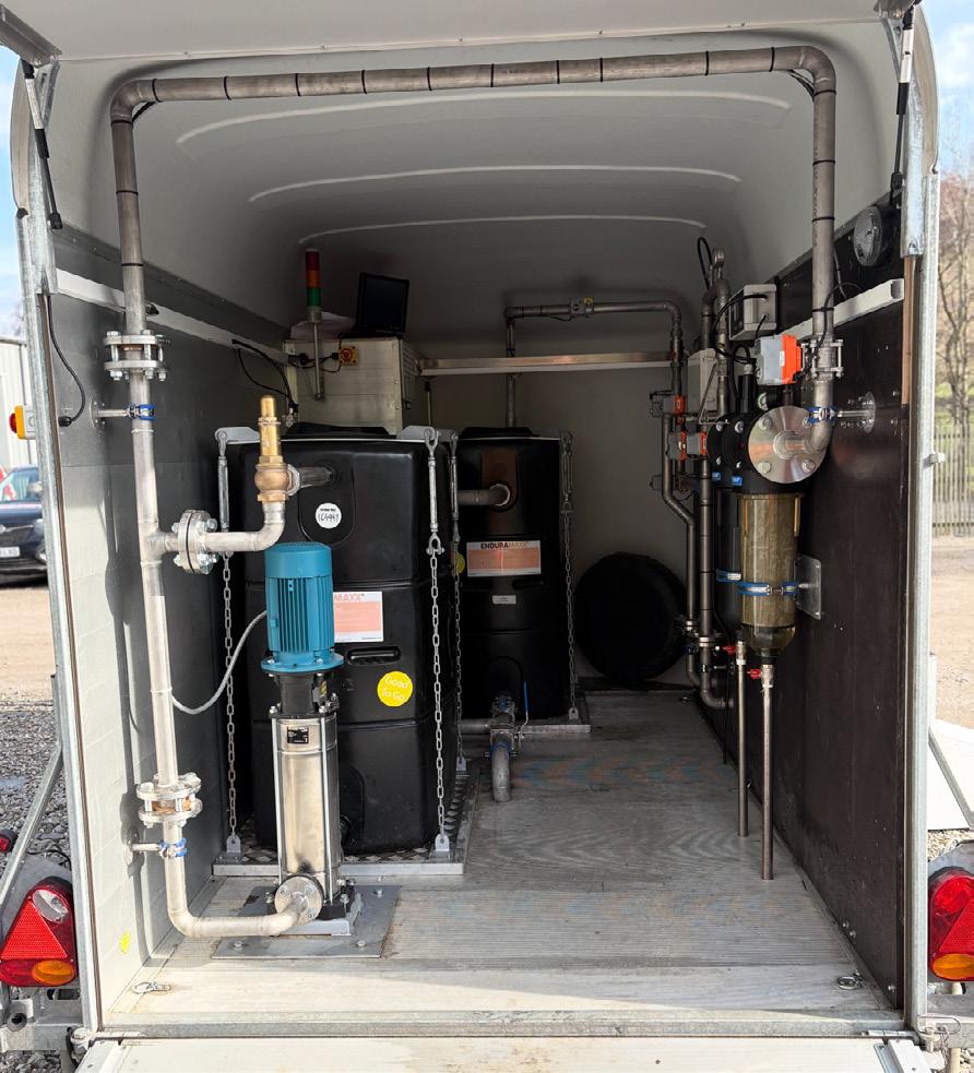

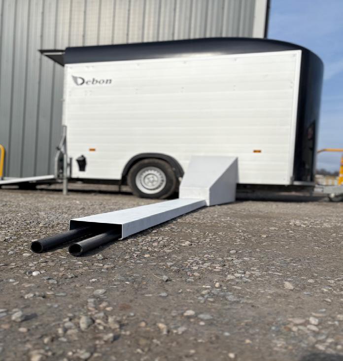
4.4b External pipework with pressure protection and insulation.
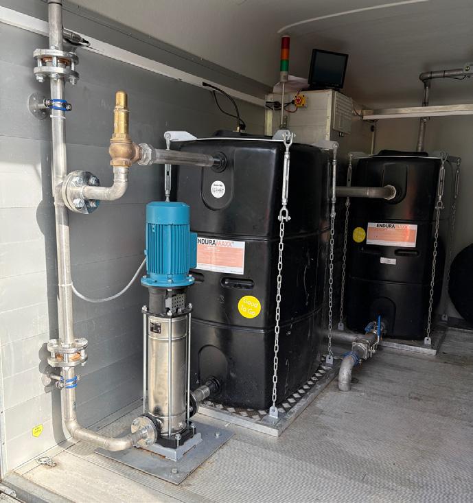
Fig. 4.4c De-gassing tanks, motive pump and over pressure protection system.
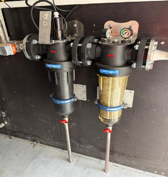
Fig 4.4d Water treatment system (filtration & UV sterilisation).
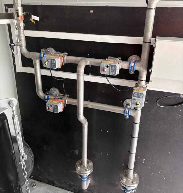
Fig 4.4e Directional valves, flow meters, pressure sensors & control systems.

4.5 All exposed pipework between the FLoMaX, and loop under test, is protected by a 3mm insulated steel plate enclosure for the protection of operators from high pressure fluid release and the avoidance of external temperature interference.
4.6 The position of the loop is confirmed by GPS and data is obtained, interpreted, stored and exported electronically to prevent malicious adjustment.
4.7 The final design for the FLoMaX was granted a patent, in the UK, on the 1st November 2023; UK patent No. GB2600686[12].
4.8 Specific international patent protection applications have been submitted to other countries as follows:-
i) Australia 3rd June 2023[13]
ii) Canada 5th May 2023[14]
iii) China 14th June 2023[15]
iv) Europe 24th May 2023[16]
v) Hong Kong 12th August 2022[17]
vi) USA 26th April 2023[18]
4.9 The Hong Kong patent was granted on the 31st May 2024; Hong Kong patent No. HK40065930[19].
4.10 Although initially designed to undertake testing in accordance with the European standard, BS EN 805:2000, the FLoMaX can also be programmed to work to the parameters in the USA standard IGSHPA 2017, and any parameters contained in the forthcoming North American standard ANSI/CSA/IGSHPA C448.
5. Benefits
5.1 Integration of a range of treatment and monitoring systems which have been condensed into an easily transportable and robust unit for use at the point of installation.
5.2 Reliable recording of data.
5.3 Interpretation, storage and export of data.
5.4 Avoidance of malicious data adjustment.
5.5 Fully automated with minimal operator input.
5.6 Full automation enables the drilling crew to continue to drill whilst testing is undertaken. This increases drilling productivity.
5.7 Protection of operators from risk of high-pressure fluid and debris release.
5.8 Confirmation that data generated is not affected by external temperature interference, including direct sunlight.
5.9 Prevention of water/aquifer contamination.

5.10 Confirmation of loop performance with regard to integrity and system design.
5.11 Confirmation of compliance with named standards in SI 651:2023, thereby avoiding the requirement for an environmental permit, under the Environmental Permitting Regulations 2016.
5.12 Accredited apparatus with consistent results, to enable quality certification for the loop. This extends the product warranty to the entire ground source installation.
5.13 The Drilling contractor can confirm the installation complies with the design specification and gets paid.
5.14 Installers, in particular ones who are serving the large district heating scheme sector and projects which involve building on top of the borefield, can be confident that the loops will perform as intended and do not have latent defects.
6.1 A prototype unit has been built and installed within a towable trailer which it is envisaged will be how the FLoMaX will be supplied as site testing equipment for hire.
6.2 The prototype is now ready for demonstration to potential users.
6.3 A further patent application was submitted on the 19th September 2024 for additional evaluation of loops at the point of installation. Application No. 2413823.2[20]. The supplementary modification will confirm the actual depth of the loop and also, it’s spatial orientation. This will enable an image of the entire borefield in 3-Dimensions to be prepared for evaluation of any potential loop energy transfer competition. The 3D image will also identify a loop
which has previously been approved for commissioning but has been compromised by subsequent drilling activities.
6.4 Envirohire Ltd are actively seeking national and international partners to help to develop worldwide marketing and roll out of the product.
1. BS EN 805:2000. Water Supply – Requirements for systems and components outside buildings. British Standards Institute.
2. British Drilling Association, Geothermal Drilling Course, Session 4, Flow & Pressure Testing.
3. Safety Requirements for Pressure Testing, GS4 (Fourth Edition). Health & Safety Executive.
4. Pressure Test Safety, Contract Research Report 168/1998. Health & Safety Executive.
5. The Environmental Permitting Regulations (England and Wales) (Amendment) (England) Regulations 2023, No. 651.
6. The Closed-loop Vertical Borehole, Design, Installation and Materials Standards, issue 1.0, dated 2020. GSHPA.
7. The Shallow Ground Source Standard, Version 2, dated January 2018. GSHPA.
8. The Thermal Pile, Design, Installation and Materials Standards, Version 2, dated September 2018. GSHPA.
9. Closed-Loop/Geothermal Heat Pumps Systems, Design and Installation Standards, 2017. IGSHPA.
10. ASTM F2164, Field Leak Testing of Polyethylene and Crosslinked Polyethylene Pressure Piping Systems Using Hydrostatic Pressure. American Society for Testing and Materials.
11. UK Intellectual Property Office, Registration Certificate UK0000368138.
12. UK Patent GB2600686 B. Methods for Use in Testing the Integrity of a Ground Source Heat Exchanger Installations.
13. IP Australia, Application number 2021369759.
14. Innovation, Science & Economic Development Canada. Application No. 3196552.
15. The State Intellectual Property Office of the Peoples’ Republic of China. Application number 202180073577.3
16. European Patent Office. Application number 21802396.8.
17. Patents Registry Intellectual Property Department, The Hong Kong Special Administration Region. Patent Application No. 2017111.2
18. United States Patent & Trademark Office. Application number 18/034,024.
19. Patents Registry Intellectual Property Department, The Hong Kong Special Administration Region. Patent number HK40065930 B.
20. UK Intellectual Property Office. Application No. GB2413823.2.
