220 220 240 INDUSTRIAL CATALOGUE EN DE
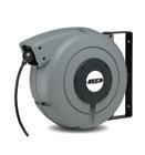
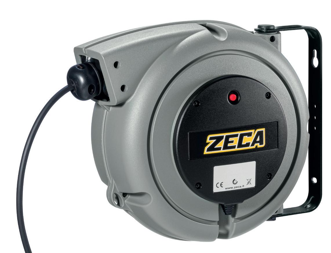
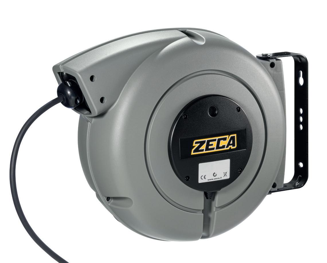
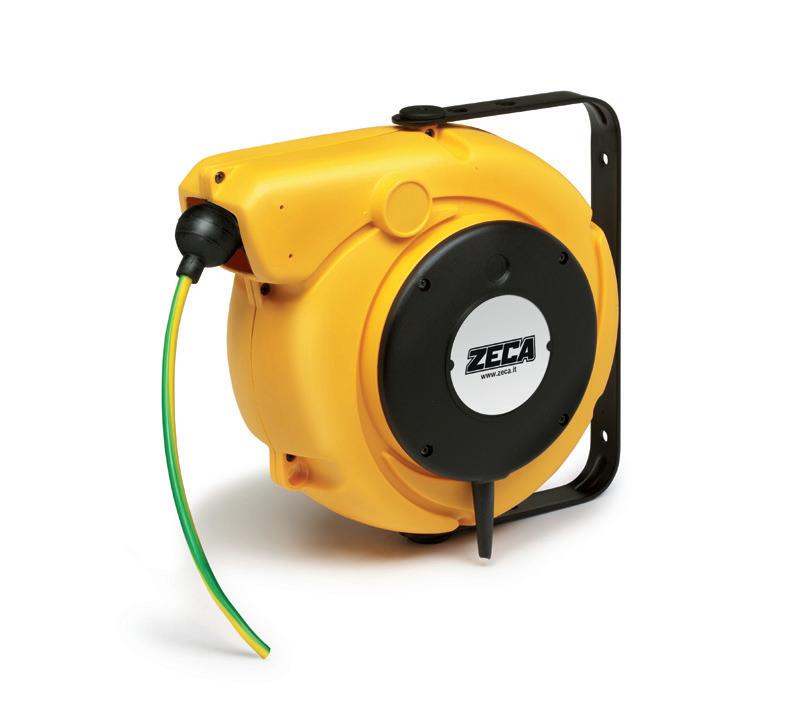
Since 1929, Zeca has responded with excellent products to the needs of anyone who works in garages, industry and on construction sites. At the Feletto plant in the province of Turin we produce cable reels, hose reels, lamps, extensions, balancers and garage tools.
Our products are recognised in Italy and worldwide for their practicality, durability and above all for their safety, even in extreme situations of use. We are a leader in the production of reels, but over the years our range has expanded to numerous other references, to meet all of our customers’ requirements.
2
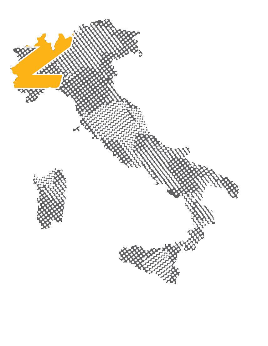
90 countries world wide served by our products, across 5 continents
OUR COMPANY

The Zeca production plants, logistics warehouses and offices have been expanded several times over the years, in parallel with the constant growth of the company.
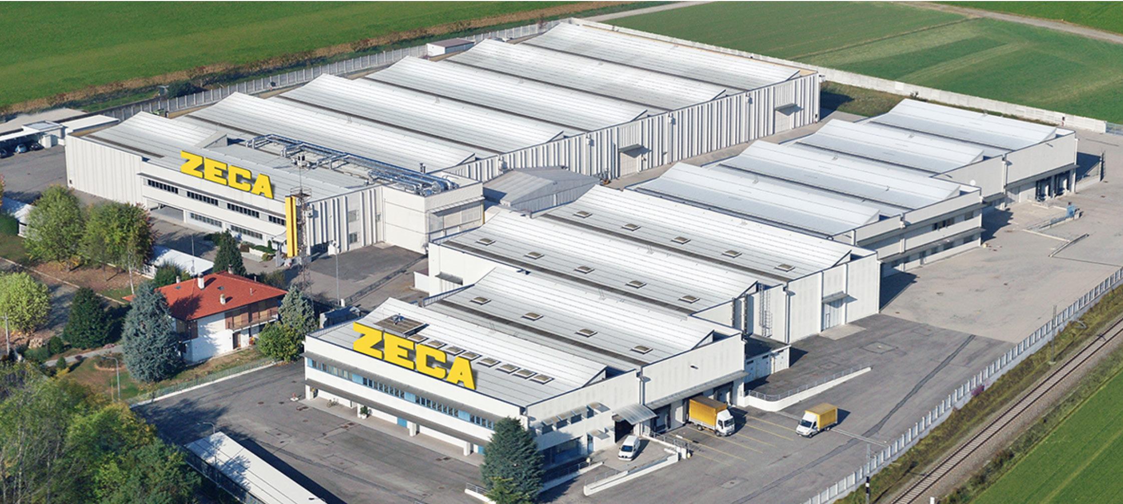
Today they occupy 3 interconnected plants, with more than 15 thousand m² of total indoor space. A good 300 m² are dedicated to our exclusive research and development laboratory, where we perform numerous in-house quality and durability tests.
FELETTO (TURIN)
3 Production plants
Total covered area + 15,000 sqm
Total area 170,000 sqm
3

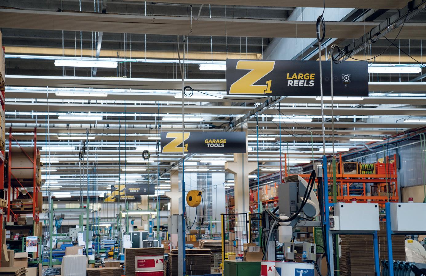
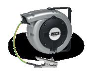
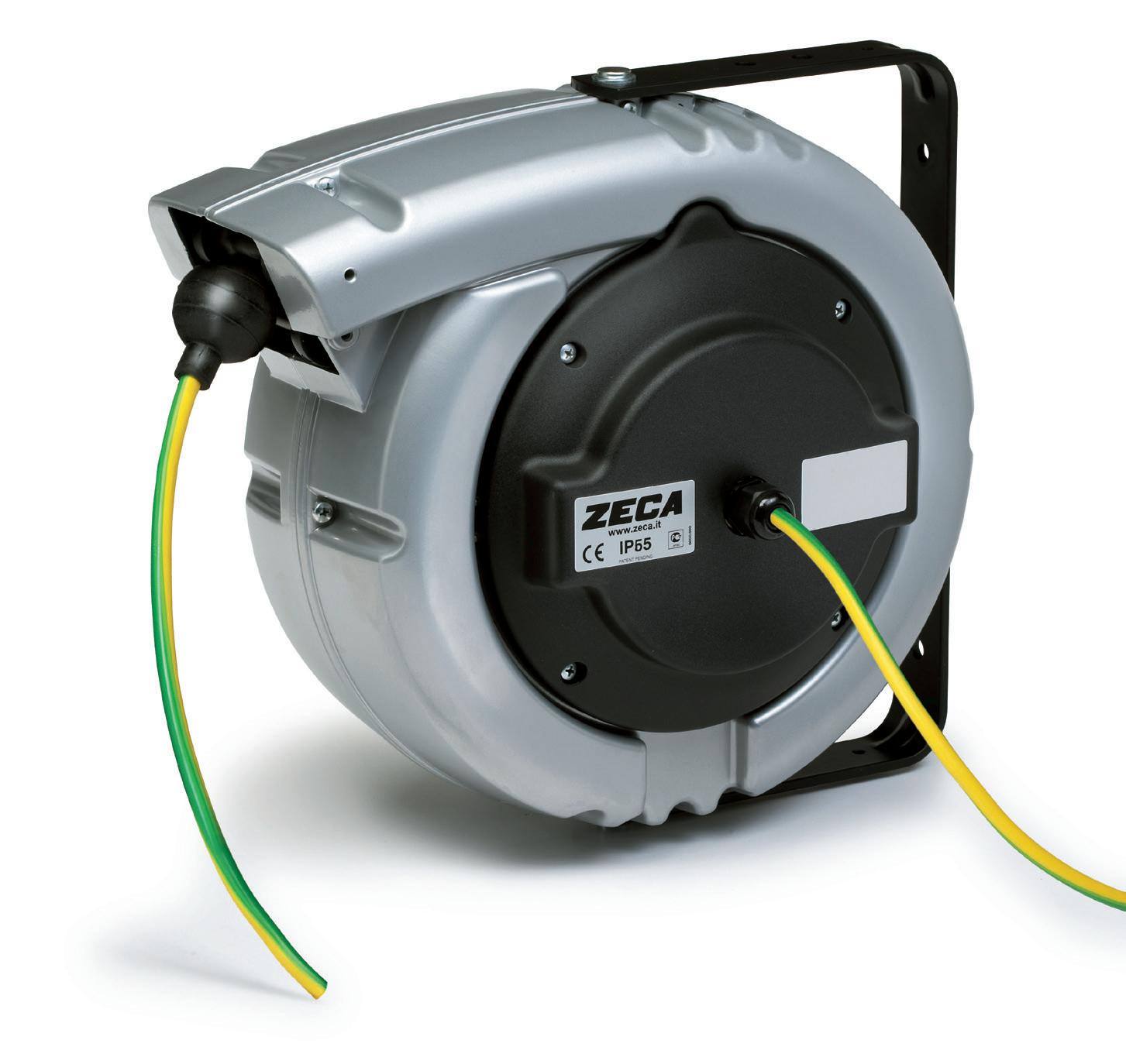
Industrial reels for grounding Kabelaufroller für die Erdung 43 - 52 Cable reels for battery chargers Kabelaufroller für Ladegeräte 53 - 59 Extension reels Verlängerungskabel 61 - 66 Industrial reels Kabelaufroller für die Industrie 5 - 42 Lamps Leuchten 67 - 70 Balancers Federzüge 71 - 74 Hose reels Schlauchaufroller 75 - 95 Zetek air blow gun Zetek Druckluftpistolen 96 - 97 Rotozeca for safety barriers Kabelaufroller für Absperrungen 60 pag. / Seite
Industrial catalogue 240 INDEX
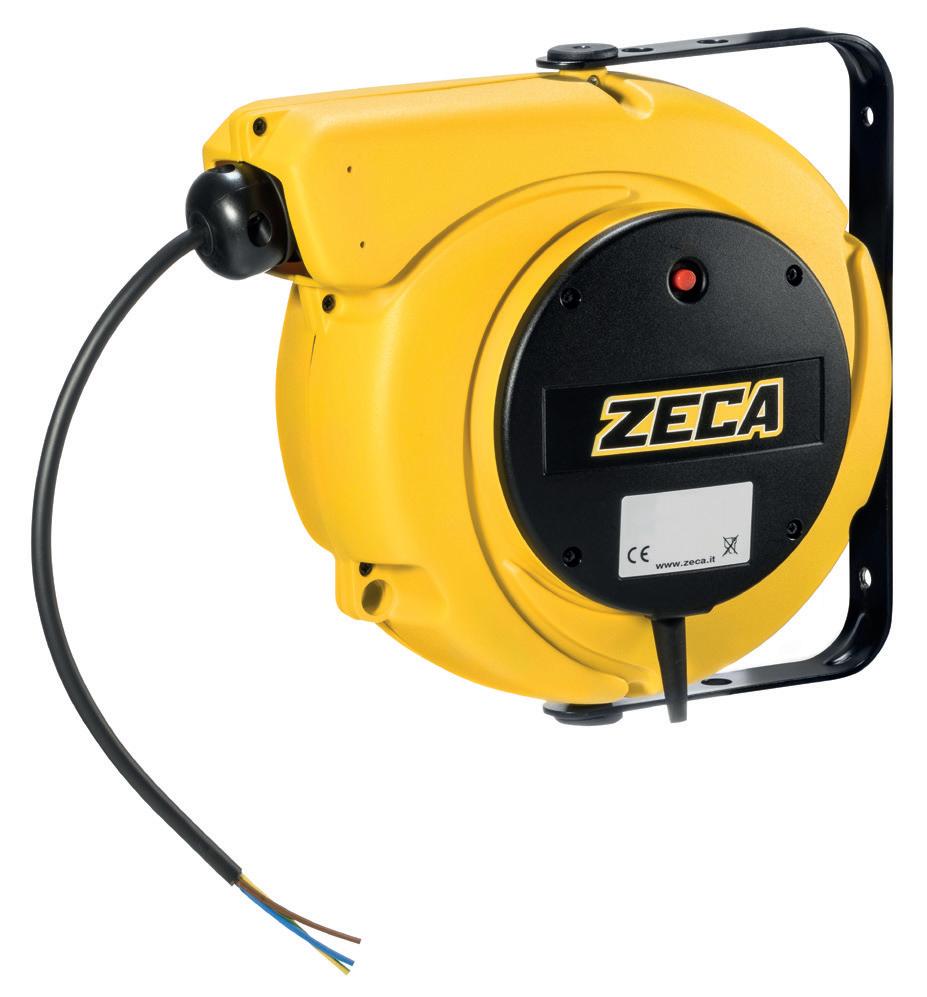
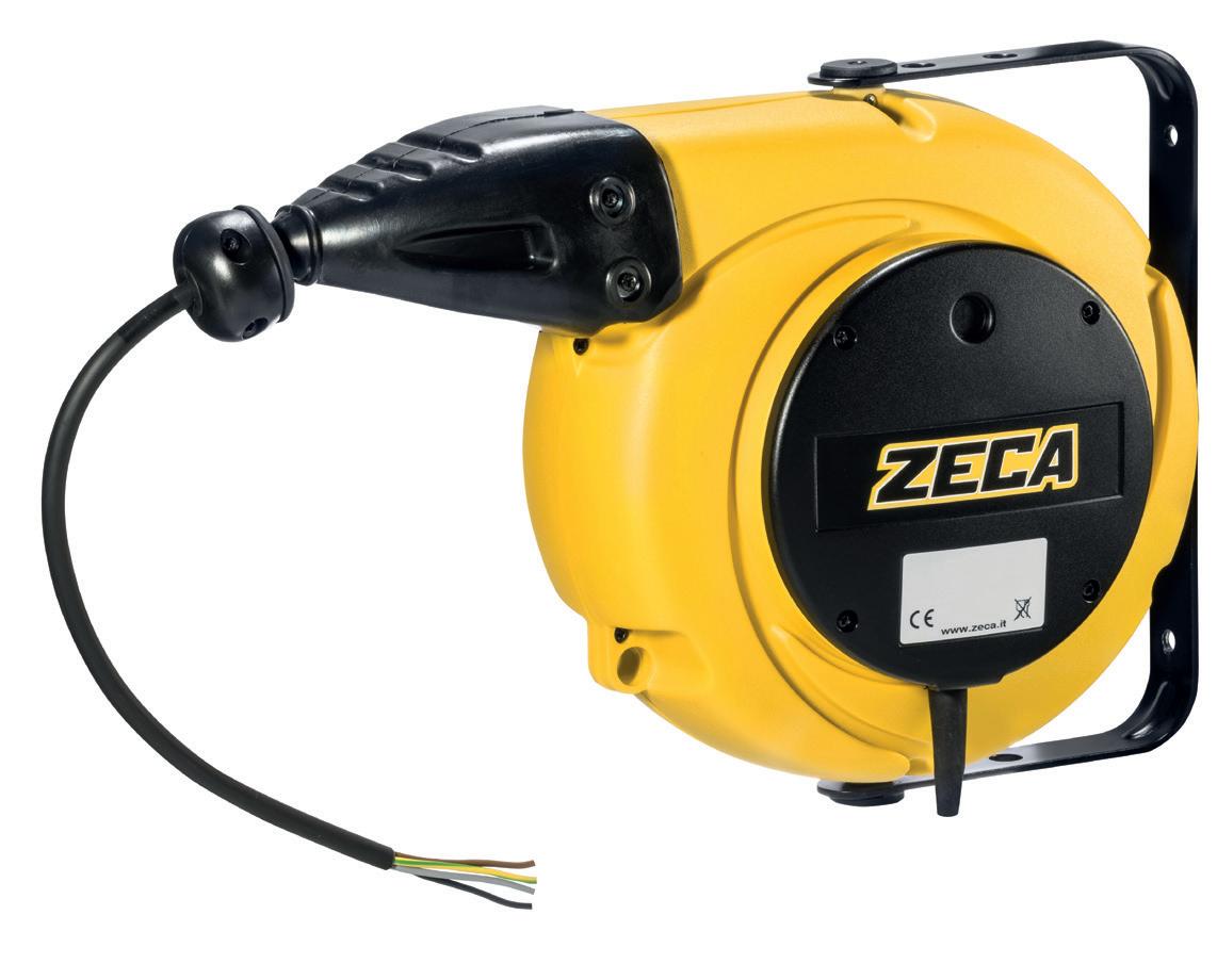
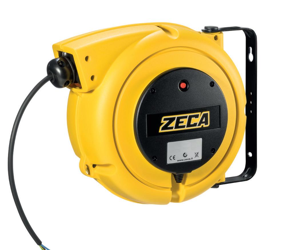
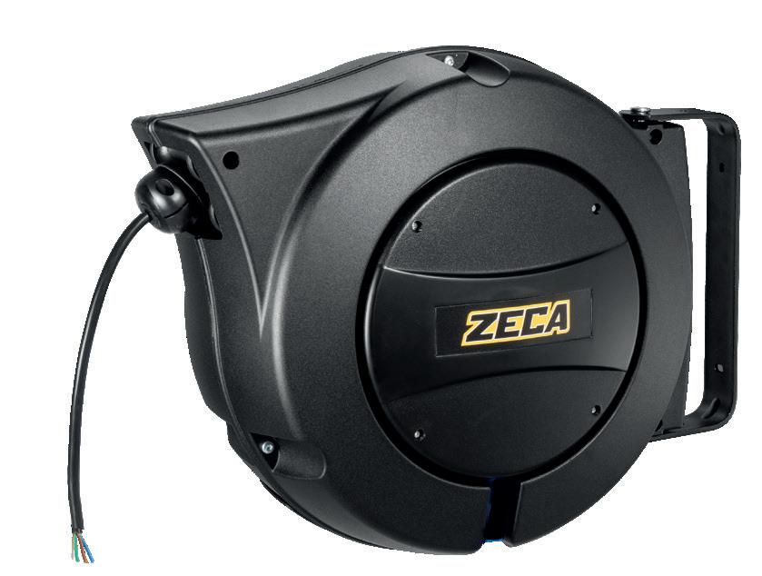
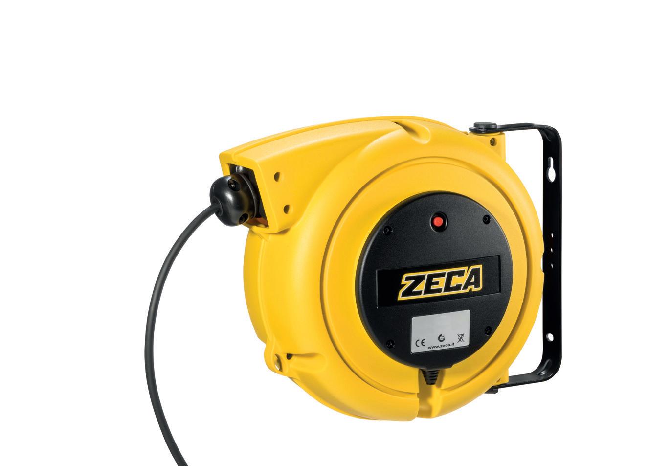
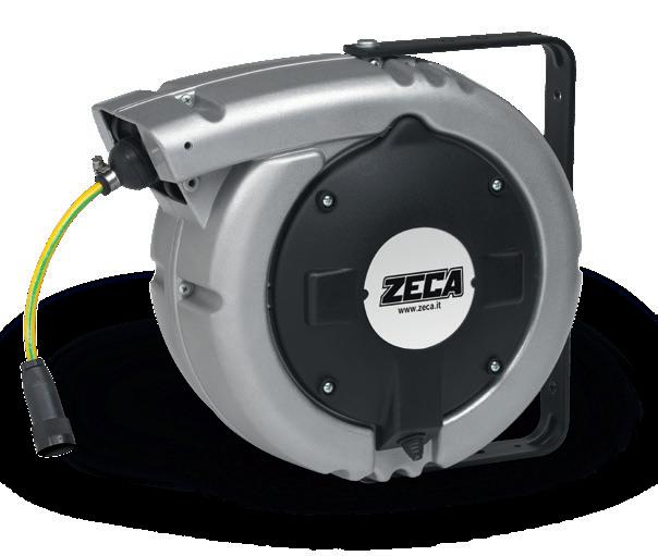
Industrial cable reels
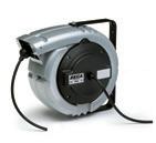
9000 series page 7
5000 series page. 8
4000 series page 10
7000 series page. 11

AL BLACK series page. 13
6000 series page 14
1400 series page 20
1700 series page. 24
1800 series page 30
Dataflux series page. 35
Twin Reels series page. 38
5
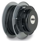
INDUSTRIAL CA BLE REELS
A COMPLETE RANGE TO FULFILL
ALL YOUR PROFESSIONAL NEEDS.
In this section you will find the complete range of our reels. Some models are available complete with socket plugs (p. 61- p.66)
KABELTROMMELN
On our webpage www.zeca.it a search engine will suggest you, by inserting the needed features (coiled meters, number of conductors, conductors section, IP protection degree, etc.) the reel which suits you.
The range proposed by Zeca is very wide. In any case, if you have a particular need, a cable of non-standard production etc…, our technical department is at your complete disposal for helping you. Please send an e-mail indicating your needs.
■ OPTIONAL FOR REELS
ART. 949/5000 for 5000 reels
ART. 949/804-4000 for 4000 reels
ART. 949/805-7000 for 7000 reels
ART. 949/PR for 6000 PR reels
Please feel free to discuss any needs you may have with our sales network or our in-house technical department. We’ll find the right solution together.
Wir bitten Sie, sich mit Ihrem Bedarf an unser Vertriebsnetz oder an unsere technische Abteilung in der Zentrale zu wenden. Wir werden gemeinsam die richtige Lösung finden.
■ EN Optional device to make the bracket fastened. Essential for ceiling application.
■ DE Optionsvorrsichtung um den Befestigungsbügel zu befestigen. Sie ist unentbehrlich für die Installation.
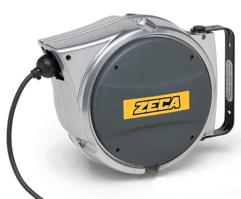
6
NO
■ EN ■ DE
KOMPLETTES SORTIMENT ZUM ERFÜLLEN ALLE IHRE BERUFLICHEN BEDÜRFNISSE.
Mobile application Mobile application
INDUSTRIELLE
EIN
• Shock resistant plastic external case.
• Ratchet stop device every 50 cm easily removed if constant traction of cables is required.
• Protection degree IP42.
• Slipring with brass rings and brushes.
• Working temperature: -5°C/+50°C.
• Double earth contact.
• Außengehäuse aus schlagfestem Kunststoff.
• Die Trommeln haben eine Rücklaufsperre mit Zahnarretierung für das Kabel, einsetzbar im Abstand von 50 cm und leicht ausschaltbar.
• Schutzart IP42.
• Umgebungstemperatur -5°C/+50°C.
• Doppelter Erdungskontakt.
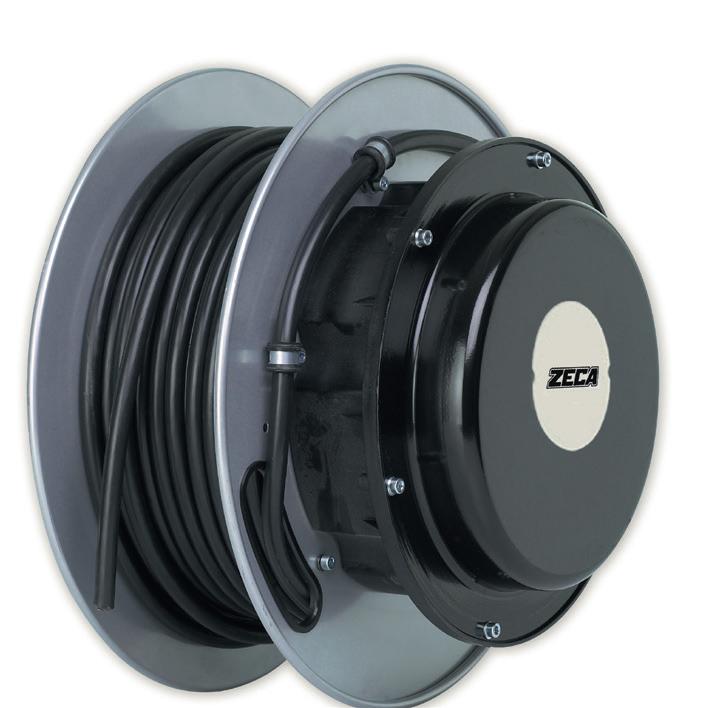
7
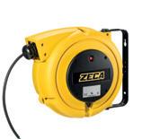
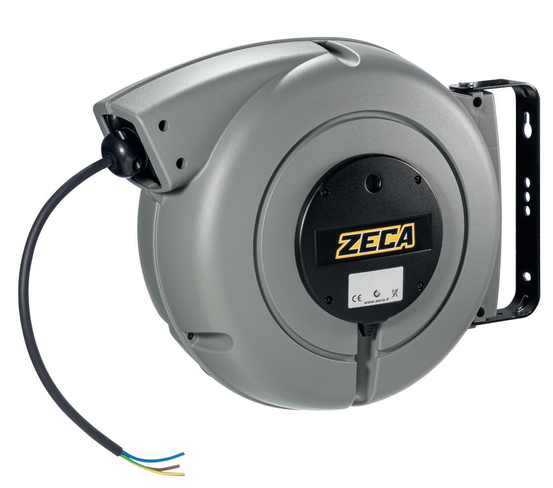
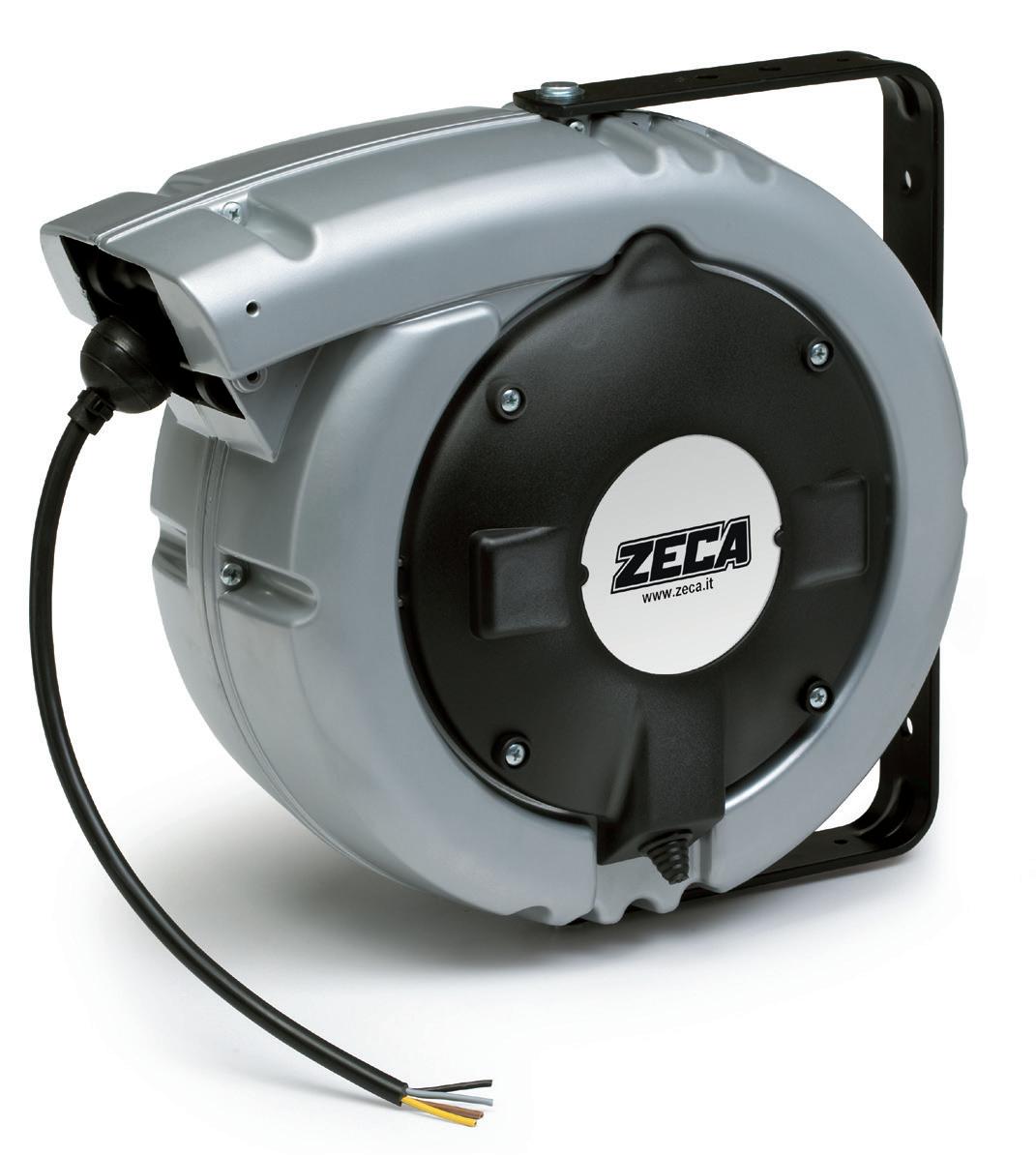
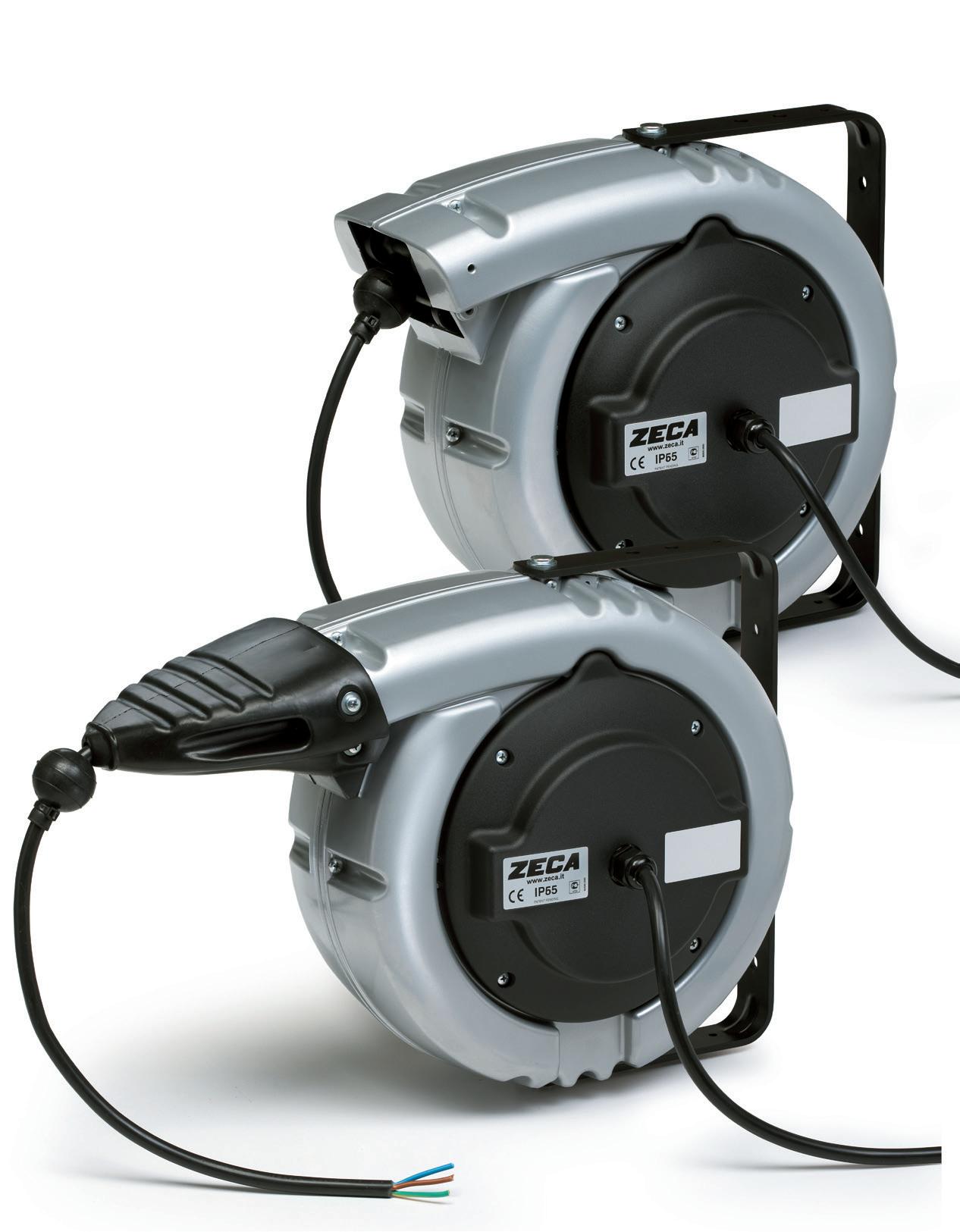
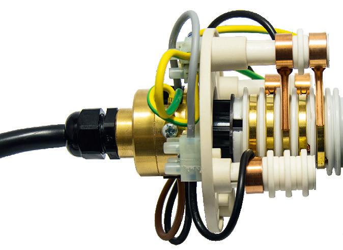
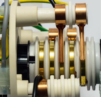
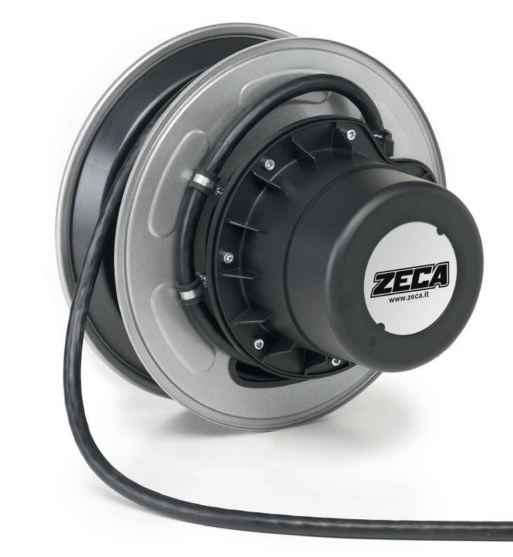
Number of conductors Conductor sections (mm2) Cable length (m) ART. KW (20°C) KW (20°C) Cable mm Ø Thermal switch Max V Cable type 1x 6 7 9006 5,5 NO PVC 2x 1 8 9001 230V 1,1 230V 1,6 6,5 SI 500 PVC 1,5 6 9002 1,4 1,9 8 SI 500 PVC 3 G 1 7 9003 1,1 1,6 6,5 SI 500 PVC 1,5 6 9004 1,4 1,9 7,5 SI 500 PVC 100 mm 240x195x120 Kg 3,0 1 EN 61242 EN 60335-1 2014/35/UE 2006/42/UE 2011/65/UE 7mm 0,3in R95mm 3,7in 100mm 3,9in 215mm 8,5in 105mm 4,1in dimensions 9000 TECHNICAL FEATURES TECHNISCHE MERKMALE ■ EN ■ DE 9000 SERIES 9000 SERIES
Models with Schuko plug and socket - See page 65
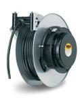
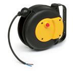
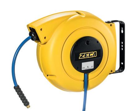
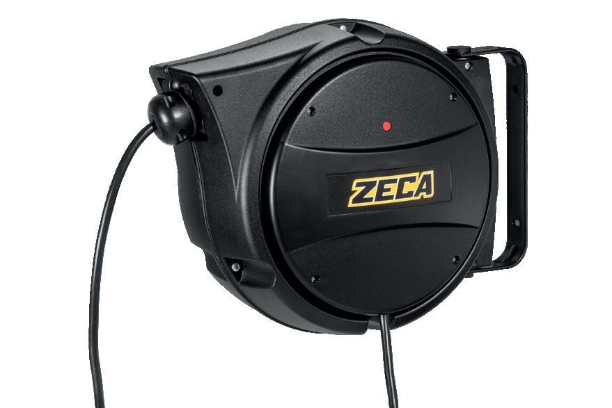
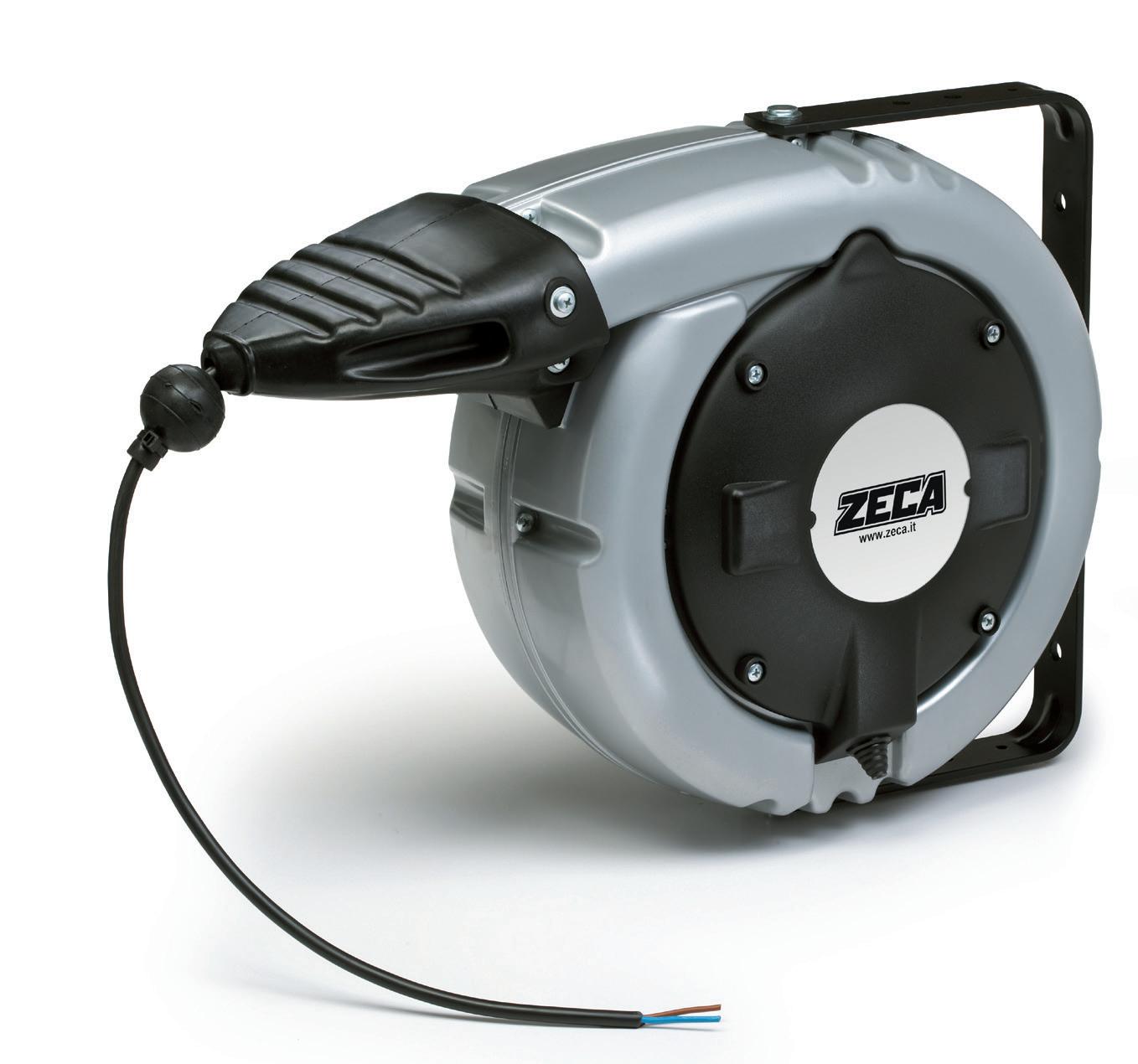
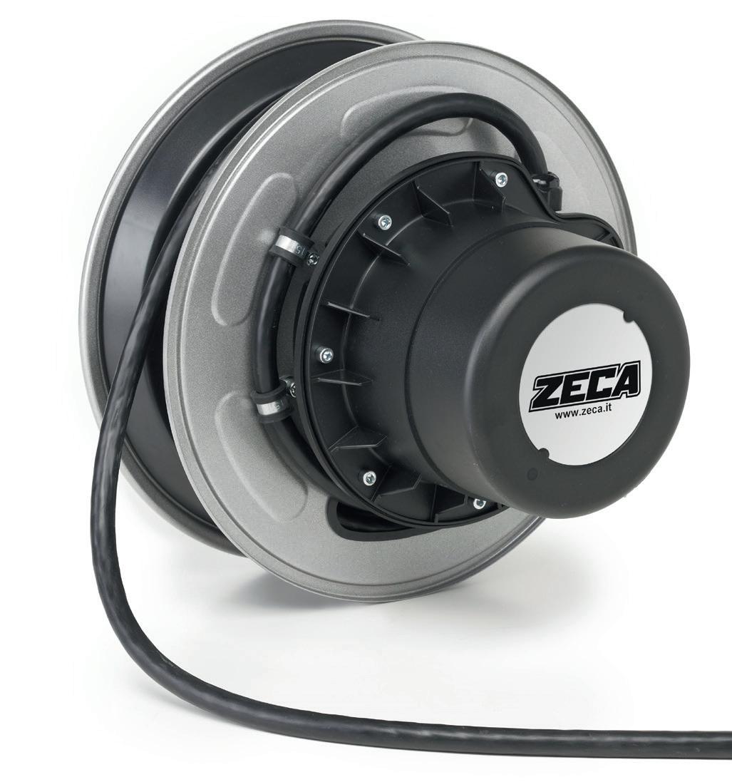
5000 XF SERIES
TECHNICAL FEATURES
Shock resistant plastic external case.
• Cable roller guide.
• Ratchet stop device every 50 cm., easily removed if constant traction of cable is required.
• Double earth contact.
• Collector insulating power 2,5 Kv.
• Slipring with brass rings and brushes.
• Working temperature -5°C/+50°C.
• Delivered without cable at feeding side.
• Available both with PVC cable and rubber cable.
TECHNISCHE MERKMALE ■ DE
• Außengehäuse aus schlagfestem Kunststoff.
• Kabelführungsöffnung mit Rollen.
• Kabelrücklaufsperre mit Zahnarretierung alle 50 cm, leicht auszuschalten, falls das Kabel kontinuierlich in Anspannung sein soll.
• Doppelter Erdungskontakt.
• Schleifring Isolierungspannung 2,5 Kv.
• Schleifring mit Messingringen und Bürsten.
• Umgebungstemperatur -5°C/+50°C.
• Geliefert ohne Kabel an der Zuführungseite.
• Lieferbar mit PVC und Gummikabel.
SPECIAL VERSION ART.5831/NT Cable reel with same characteristics as 5831/XF, but without circuit breaker. Max. voltage 48V. N.B. In case of use with voltage higher than 48V, consider a suitable amperometric protection at the top of the reel based on a max. power of 900W.
SPECIAL VERSION ART.5831/IP65 Cable reel with same characteristics as serie XF, in IP65 tight outfit, without circuit breaker. N.B. Cable reel without circuit breaker. In case of use with voltage higher than 48V, consider a suitable amperometric protection at the top of the reel based on a max. power of 900W.
SPECIAL VERSION ART.5827/IP65 Cable reel with same characteri tics as serie XF, in IP65 tight outfit, without circuit breaker. N.B. Cable reel without circuit breaker. In case of use with voltage higher than 48V, consider a suitable amperometric protection at the top of the reel based on a max. power of 1200W.
8 Number of conductors Conductor sections (mm2) Cable length (m) ART. KW (20°C) KW (20°C) Cable mm Ø Thermal protector Oversized collector Max V Cable type 1 x 2.5 16.5 5836/ XF 5.5 NO PVC 6 14 5834/XF 5.5 NO PVC 16 10 5832/XF 8 NO PVC 2 x 1 15.5 5831/XF 230V 0.9 230V 1.4 6 YES 500 PVC 11.5 5831/XF RNF 8 YES 750 RUBBER 1.5 12.5 5830/XF 1.1 1.6 8 YES 500 PVC 2.5 10 5829/XF 1.8 2.3 9 YES 500 PVC 3 G 1 14 5828/XF 0.9 1.4 6.5 YES 500 PVC 1.5 11.5 5827/XF 1.2 1.8 7 YES 500 PVC 9.5 5827/XF RNF 9.5 YES 750 RUBBER 2.5 8.5 5825/XF 1.9 2.5 10 YES 500 PVC 5826/XF 4 G 1 12 5824/XF 400V 1.1 400V 1.6 7 NO 500 PVC 1.5 9.5 5823/XF 1.4 1.9 8.5 NO 500 PVC 2.5 7 5821/XF 2.0 2.7 11 NO 500 PVC 5822/XF 5 G 1 9 5844/XF 1.0 1.5 7.5 NO 500 PVC 1.5 7 5843/XF 1.4 1.9 9.5 NO 500 PVC 7 x 1 7.5 5840/XF 3 A 8.5 NO 500 PVC 1.5 7 5839/XF 4.5 A 10.5 NO 500 PVC 8 x 1 7 5838/XF 3 A 10 NO 500 PVC IP42 mm 300x295x155 Kg 3,5 57 1 200mm 7,9in 305mm 12in 8mm 0,3in 30° 45° 280mm 11in 145mm 5,7in dimensions 5000 •
■ EN
EN 61242 EN 60335-1 2014/35/UE 2006/42/UE 2011/65/UE 5000 SERIES
5000 XL SERIES
TECHNICAL FEATURES
• Shock resistant plastic external case
• Rubber cable guide
• Ratchet stop device every 50 cm., easily removed if constant traction of cable is required
• Double earth contact
• Collector insulating power 2,5 Kv.
• Slipring with brass rings and brushes
• Working temperature -5°C/+50°C
• Delivered without cable at feeding side
• Available both with PVC cable and rubber cable.
TECHNISCHE MERKMALE
• Außengehäuse aus schlagfestem Kunststoff
• Kabelführungsöffnung aus Gummi
• Kabelrücklaufsperre mit Zahnarretierung alle 50 cm, leicht auszuschalten, falls das Kabel kontinuierlich in Anspannung sein soll
• Doppelter Erdungskontakt
• Schleifring Isolierungspannung 2,5 Kv
• Schleifring mit Messingringen und Bürsten.
• Umgebungstemperatur -5°C/+50°C
• Geliefert ohne Kabel an der Zuführungseite
• Lieferbar mit PVC und Gummikabel.
IP43
■ OPTIONAL ACCESSORIES
ART. 5100
Transformation kit from XF to XL.
Umbausatz XF zu XL.
9 5000 SERIES 200mm 7,9in 390mm 15,4in 8mm 0,3in 280mm 11in 145mm 5,7in dimensions 5000 Number of conductors Conductor crosssections (mm2) Cable length (m) ART. KW (20°C) KW (20°C) Cable mm Ø Thermal switch Oversized collector Max V Cable type 1 x 2.5 16.5 5897/ XL 5.5 NO PVC 6 14 5896/XL 5.5 NO PVC 16 10 5894/XL 8 NO PVC 2 x 1 15.5 5893/XL 230V 0.9 230V 1.4 6 YES 500 PVC 11.5 5893/XL RNF 8 YES 750 RUBBER 1.5 12.5 5892/XL 1.1 1.6 8 YES 500 PVC 2.5 10 5829/XF + 5100 1.8 2.3 9 YES 500 PVC 3 G 1 14 5890/XL 0.9 1.4 6.5 YES 500 PVC 1.5 11.5 5889/ XL 1.2 1.8 7 YES 500 PVC 9.5 5889/XL RNF 9.5 YES 750 RUBBER 2.5 8.5 5888/XL 1.9 2.5 10 YES 500 PVC 5826/XF + 5100 4 G 1 12 5878/XL 400V 1.1 400V 1.6 7 NO 500 PVC 1.5 9.5 5877/XL 1.4 1.9 8.5 NO 500 PVC 2.5 7 5821/XF + 5100 2.0 2.7 11 NO 500 PVC 5822/XF + 5100 5 G 1 9 5844/XF + 5100 1.0 1.5 7.5 NO 500 PVC 1.5 7 5843/XF + 5100 1.4 1.9 9.5 NO 500 PVC 7 x 1 7.5 5870/XL 3 A 8.5 NO 500 PVC 1.5 7 5869/XL 4.5 A 10.5 NO 500 PVC 8 x 1 7 5838/XF + 5100 3 A 10 NO 500 PVC mm 410x305x185 Kg 4,0 48 1 EN 61242 EN 60335-1 2014/35/UE 2006/42/UE 2011/65/UE
■ EN
■ DE
TECHNICAL FEATURES
• Shock resistant plastic external case
• Cable roller guide
Ratchet stop device every 50 cm., easily removed if constant traction of cable is required
• Double earth contact
• Collector insulating power 2,5 KV.
• Slipring with brass rings and brushes
• Working temperature -5°C/+50°C
• Delivered without cable at feeding side
• Available both with PVC cable and rubber cable.
• Außengehäuse aus schlagfestem Kunststoff
• Kabelführungsöffnung aus Gummi
Kabelrücklaufsperre mit Zahnarretierung alle 50 cm, leicht auszuschalten, falls das Kabel kontinuierlich in Anspannung sein soll
• Doppelter Erdungskontakt
• Schleifring Isolierungspannung 2,5 Kv
• Schleifring mit Messingringen und Bürsten.
• Umgebungstemperatur -5°C/+50°C
• Geliefert ohne Kabel an der Zuführungseite
• Lieferbar mit PVC und Gummikabel.
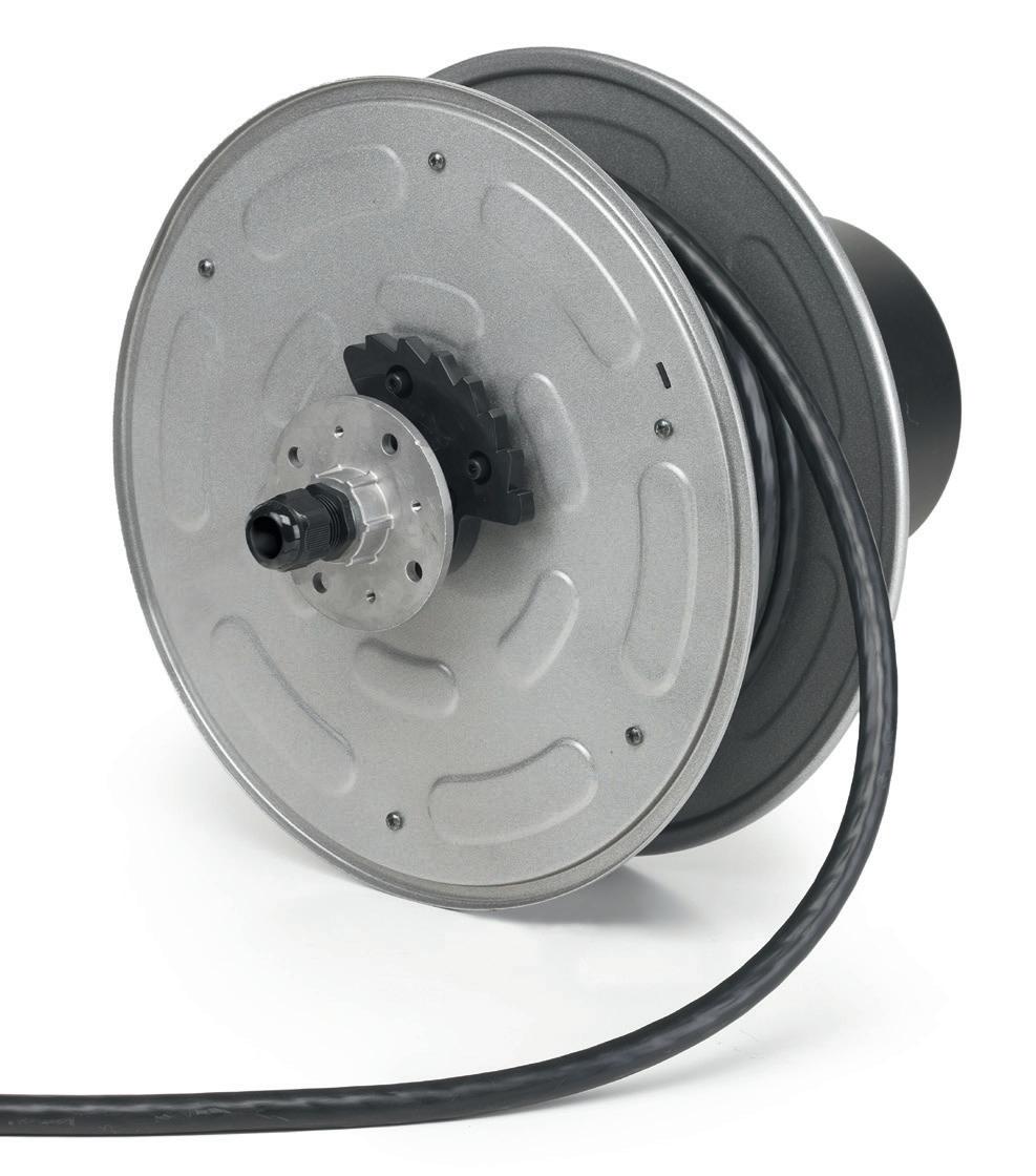
10 5000 SERIES Number of conductors Conductor crosssections (mm2) Cable length (m) ART. KW (20°C) KW (20°C) Cable mm Ø Thermal switch Max V Cable type 1 x 6 16 4106 5.5 NO PVC 16 11 4116 8 NO PVC 2 x 1 18 4210 230V 0.9 230V 1.4 6 YES 500 PVC 13 4210 RNF 8 YES 750 RUBBER 1.5 16 4215 1.1 1.6 8 YES 500 PVC 3 G 1.5 15 4315 1.2 1.8 7 YES 500 PVC 10 4315 RNF 9.5 YES 750 RUBBER 2.5 10 4325 1.9 2.5 10 YES 500 PVC 15 4325/15 8.5 YES 500 PVC 8 4325 RNF 11.5 YES 750 RUBBER 4 G 1.5 11 4415 400V 1.4 400V 1.9 8.5 NO 500 PVC 9 4415 RNF 10.5 NO 750 RUBBER 2.5 9 4425 2.0 2.7 11 NO 500 PVC 6 4425 RNF 12.5 NO 750 RUBBER 5 G 1 11.5 4510 1.0 1.5 7.5 NO 500 PVC 1.5 9 4515 1.4 1.9 9.5 NO 500 PVC 8 4515 RNF 12 NO 750 RUBBER 7mm 0,3in 170mm 6,7in 350mm 13,8in R145mm 5,7in 160mm 6,3in 804 2023 dimensions 4000 IP42 mm 335x310x185 Kg 5,0 1 44 EN 61242 EN 60335-1 2014/35/UE 2006/42/UE 2011/65/UE
■ EN ■ DE
TECHNISCHE MERKMALE
4000 SERIES
TECHNICAL FEATURES
• Shock resistant plastic external case
• Cable roller guide
Ratchet stop device every 50 cm., easily removed if constant traction of cable is required
• Double earth contact
• Collector insulating power 2,5 Kv.
• Slipring with brass rings and brushes
• Working temperature -5°C/+50°C
• Delivered without cable at feeding side
• Available both with PVC cable and rubber cable.
• Außengehäuse aus schlagfestem Kunststoff
• Kabelführungsöffnung mit Rollen
Kabelrücklaufsperre mit Zahnarretierung alle 50 cm, leicht auszuschalten, falls das Kabel kontinuierlich in Anspannung sein soll
• Doppelter Erdungskontakt
• Schleifring Isolierungspannung 2,5 Kv
• Schleifring mit Messingringen und Bürsten.
• Umgebungstemperatur -5°C/+50°C
• Geliefert ohne Kabel an der Zuführungseite
• Lieferbar mit PVC und Gummikabel
11 4000 SERIES 7000
IP42 170mm 6,7in R185mm 7,3in 490mm 19,3in 4mm 0,2in 210mm 8,3in 7000/805 VERSIONE 2023 dimensions 7000
SERIES
■ EN
MERKMALE ■ DE mm 430x400x210 Kg 8,0 - 10,0 20 1 EN 61242 EN 60335-1 2014/35/UE 2006/42/UE 2011/65/UE Number of conductors Conductor cross-sections (mm2) Cable length (m) ART. KW (20°C) KW (20°C) Cable mm Ø Thermal switch Max V Cable type 1 x 16 22 7116 8 NO PVC 2 x 1.5 27 7215 230V 1.1 230V 1.8 8 NO 500 PVC 3 G 1.5 27 7315 1.1 1.8 7 NO 500 PVC 22 7315 RNF 9.5 NO 750 RUBBER 2.5 22 7325 2.0 3.0 10 NO 500 PVC 25 7325/25 8.5 NO 500 PVC 19 7325 RNF 11.5 NO 750 RUBBER 4 G 1.5 27 7415 400V 1.1 400V 1.8 8.5 NO 500 PVC 18 7415 RNF 10.5 NO 750 RUBBER 2.5 20 7425 2.0 3.0 11 NO 500 PVC 15 7425 RNF 12.5 NO 750 RUBBER 5 G 1.5 22 7515 1.5 2.2 9.5 NO 500 PVC 17 7515 RNF 12 NO 750 RUBBER 2.5 17 7525 2.0 3.0 12.5 NO 500 PVC 12 7525 RNF 13.5 NO 750 RUBBER ART. 7000/SR ■ OPTIONAL NEW QUICK FIT SEE PAGE 12
TECHNISCHE
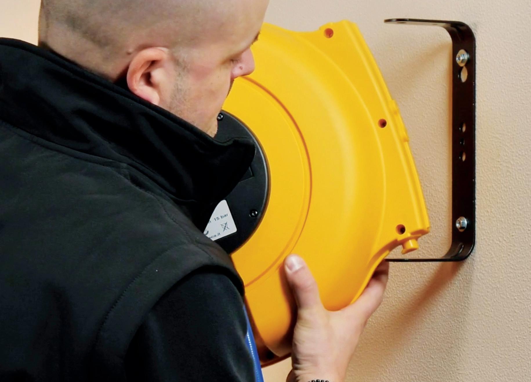
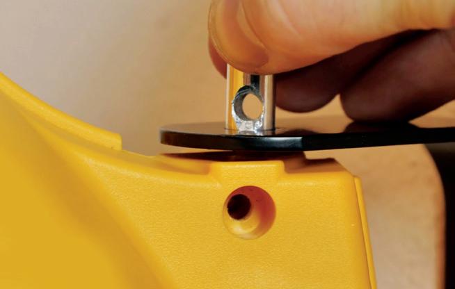
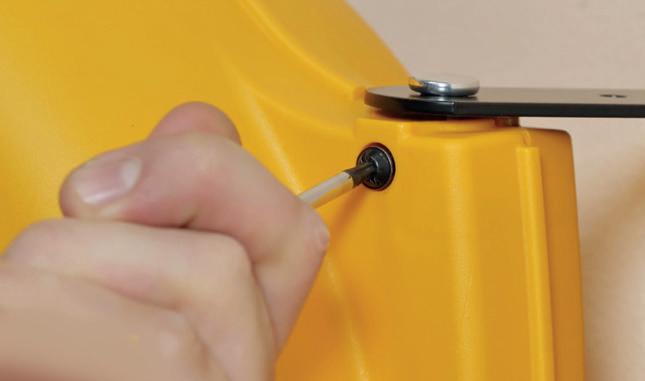
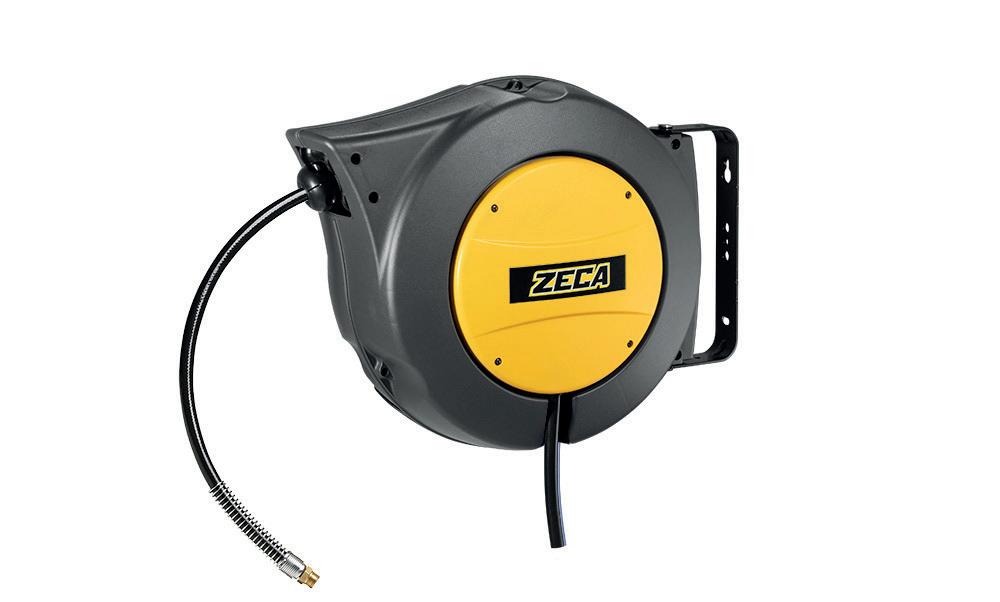

12 EASY SET-UP THE REEL CAN BE MOUNTED BY ONE PERSON IN JUST AFEW MINUTES > > 1 NEW QUICK FIT FEATURE QUICKLY CONNECT THE REEL TO ITS BRACKET AVAILABLE FOR SERIES 805 - 7000 - AM85 WACHT VIDEO FOR MORE INFO 2 3
ART. AL71-AM70/SR
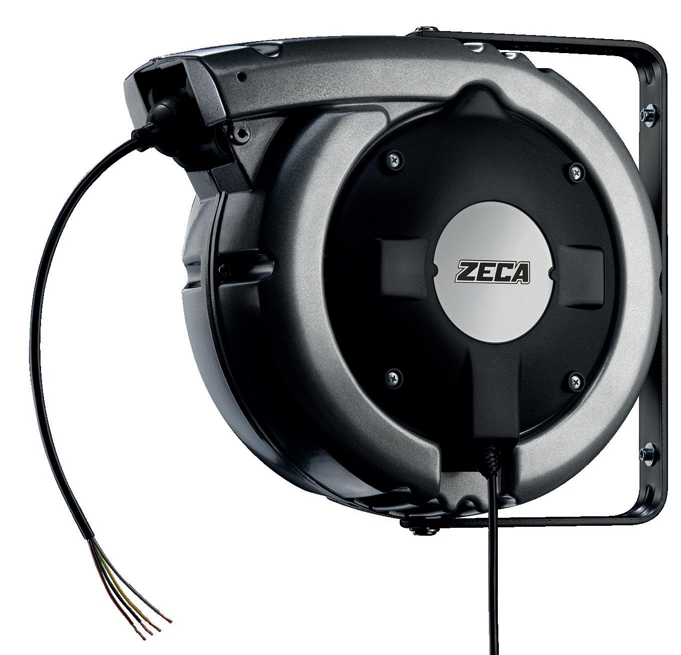
AL BLACK SERIES
ALUMINIUM BODY ALUMINIUM BODY
■ EN TECHNICAL FEATURES
• Die-cast aluminium frame painted with black epoxy powder.
• Cable roller guide
• Ratchet stop device every 50 cm. All cable reels are supplied with predisposition for cable-stop device off.
• It can be easily inserted.
• Double earth contact
• Collector insulating power 2,5 Kv.
• Brass-rings collector and special brushes with minimum impedance drop
• Slipring with brass rings and brushes
• Working temperature -5°C/+50°C
• Delivered without cable at feeding side
• Available both with PVC cable and rubber cable.
■ DE TECHNISCHE MERKMALE
• Gehäuse aus lackiertem Aluminiumdruckguss mit schwarzem Epoxidpulver.
• Kabelführungsöffnung mit Rollen
• Kabelrücklaufsperre mit Zahnarretierung alle 50 cm. Alle Kabelaufroller werden mit abgeschalteter Voreinstellung der Kabelsperrvorichtung geliefert.
• Leicht auszuschalten
• Doppelter Erdungskontakt
• Kollektor mit Messingringen und Sonderbürsten mit äußerst geringem Spannungsabfall
• Schleifring Isolierungspannung 2,5 Kv
• Umgebungstemperatur -5°C/+50°C
• Geliefert ohne Kabel an der Zuführungseite
• Lieferbar mit PVC und Gummikabel.
13 AL BLACK SERIES Number of conductors Conductor cross-sections (mm2) Cable length (m) ART. KW (20°C) KW (20°C) Cable type 3 G 2.5 15 AL41/325/15/B 230V 1.9 230V 2.5 PVC 3 G 1.5 27 AL71/315/B 1.1 1.8 PVC 3 G 1.5 22 AL71/315/B RNF 1.1 1.8 RUBBER 3 G 2.5 22 AL71/325/B 2.0 3.0 PVC 3 G 2.5 19 AL71/325/B RNF 2.0 3.0 RUBBER 3 G 2.5 25 AL71/325/25/B 2.0 3.0 PVC 4 G 1.5 18 AL71/415/B RNF 1.5 2.2 RUBBER 4 G 2.5 15 AL71/425/B RNF 2.0 3.0 RUBBER 5 G 1.5 17 AL71/515/B RNF 1.5 2.2 RUBBER 5 G 2.5 12 AL71/525/B RNF 2.0 3.0 RUBBER
NEW
mm 450x390x215 Kg 9,0 20 1 mm 360x310x185 Kg 6,0 44 1 AL71 dimensions Ø6mm Ø0,2in 160mm 6,3in 490mm 19,3in R190mm 7,5in 210mm 8,3in AL83 AL41 dimensions 6mm 0,2in 130mm 5,1in R145mm 5,7in 375mm 14,8in 165mm 6,5in SERIES AL41 / AL47 / AL48 / AL81
■ OPTIONAL
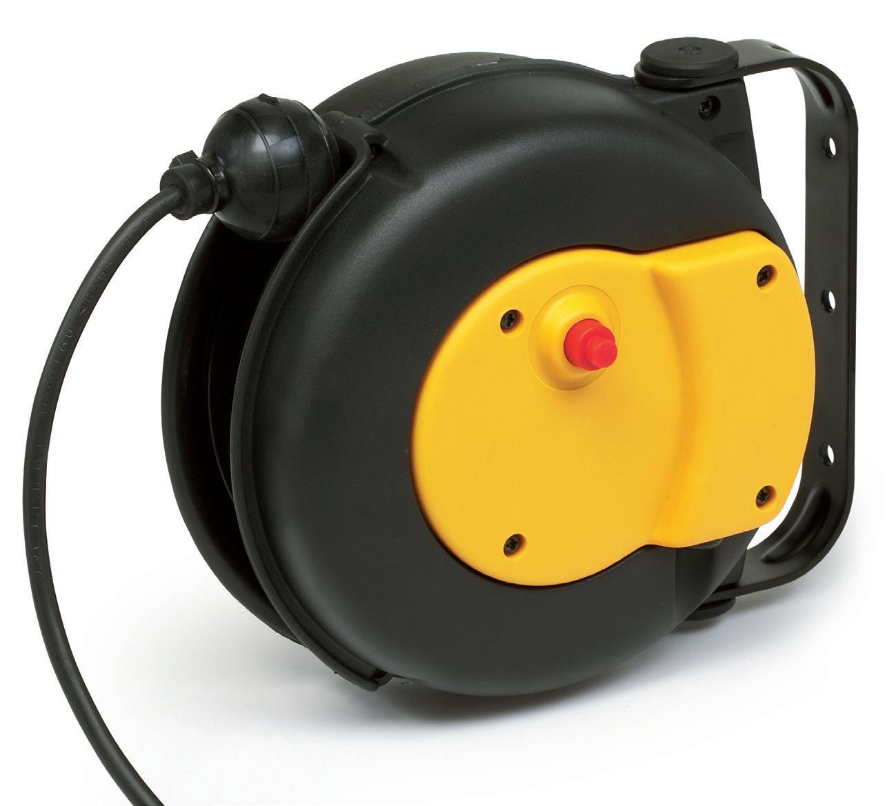
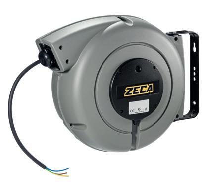
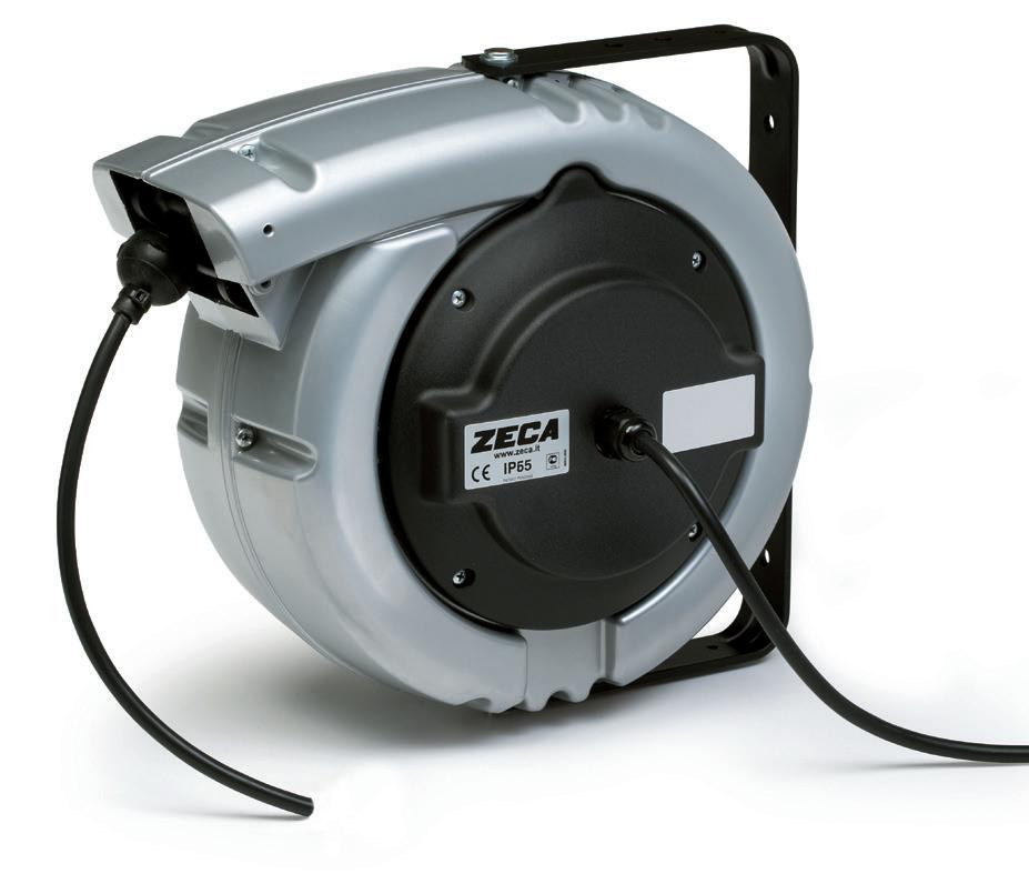
6000 PRC SERIES
• Die-cast aluminium case
• Cable roller guide
• Ratchet stop device every 50 cm. All cable reels are supplied with predisposition for cable-stop device off.
• It can be easily inserted.
• Double earth contact
• Collector insulating power 2,5 Kv.
• Brass-rings collector and special brushes with minimum impedance drop
• Slipring with brass rings and brushes
• Working temperature -5°C/+50°C
• Delivered without cable at feeding side
• Available both with PVC cable and rubber cable.
■ OPTIONAL ACCESSORIES
ART. 953
Roller cable-guide for cable reels PR series. Essential for ceiling applications.
Rollen-Kabelführungsoffnung für Serie PR. Unentbehrlich bei Deckenmontage.
TECHNISCHE MERKMALE
• Außengehäuse aus Aluminium
• Kabelführungsöffnung mit Rollen
• Kabelrücklaufsperre mit Zahnarretierung alle 50 cm. Alle Kabelaufroller werden mit abgeschalteter Voreinstellung der Kabelsperrvorichtung geliefert.
• Leicht anzuschalten
• Doppelter Erdungskontakt
• Kollektor mit Messingringen und Sonderbürsten mit äußerst geringem Spannungsabfall
• Schleifring Isolierungspannung 2,5 Kv
• Umgebungstemperatur -5°C/+50°C
• Geliefert ohne Kabel an der Zuführungseite
• Lieferbar mit PVC und Gummikabel.
14 12-16 CONDUCTORS dimensions 6000 1-10 CONDUCTORS mm 400x370x190 Kg 13,0 30 1 mm 400x390x290 Kg 13,0 24 1 EN 61242 EN 60335-1 2014/35/UE 2006/42/UE 2011/65/UE
EN ■ DE
TECHNICAL FEATURES ■
ALUMINIUM BODY ALUMINIUM BODY
6000 SERIES
IP42
(**) For these models the dimensions in the reel axis direction should be increased by 75 mm.
(**) Für diese Modelle sollten die Abmessungen in Richtung der Achse des Aufrollers um 75 mm
werden.
15 Number of conductors Conductor crosssections (mm2) Cable length (m) ART. KW (20°C) KW (20°C) Cable mm Ø Thermal switch Oversized collector Max V Cable type 1 x 2.5 30 6198/PRC 5.5 NO PVC 6 26 6195/PRC 5.5 NO PVC 16 17 6193/PRC 8 NO PVC 2 x 1.5 26 6191/PRC 230V 1.1 230V 1.8 8 NO 500 PVC 2.5 23 6189/PRC 1.8 2.5 9 NO 500 PVC 3 G 1.5 26 6186/PRC 1.1 1.8 7 NO 500 PVC 22 6186/PRC RNF 9.5 NO 750 RUBBER 2.5 17 6184/PRC 2.0 3.0 10 NO 500 PVC 6185/PRC 22 6188/PRC 8.5 NO 500 PVC 14 6184/PRC RNF 11.5 NO 750 RUBBER 6185/PRC RNF 4 G 1 26 6182/PRC 400V 0.8 400V 1.4 7 NO 500 PVC 1.5 23 6181/PRC 1.1 1.8 8.5 NO 500 PVC 18 6181/PRC RNF 10.5 NO 750 RUBBER 2.5 17 6179/PRC 2.0 3.0 11 NO 500 PVC 6521/PRC 12 6521/PRC RNF 12.5 NO 750 RUBBER 4 10 6458/PRC 3.0 4.0 14 NO 500 PVC 5 G 1.5 18 6067/PRC 1.5 2.2 9.5 NO 500 PVC 2.5 12 6022/PRC 2.0 3.0 12.5 NO 500 PVC 6068/PRC 10 6068/PRC RNF 13.5 NO 750 RUBBER 7 x 1 18 6065/PRC 3 A 8.5 NO 500 PVC 1.5 11 6069/PRC 4.5 A 10.5 NO 500 PVC 8 x 1 13 6066/PRC 3 A 10 NO 500 PVC 1.5 10 6070/PRC 4.5 A 11.5 NO 500 PVC 2.5 8 6061/PRC 7.5 A 14 NO 500 PVC 10 x 1 12 6095/PRC 3 A 13 NO 500 PVC 1.5 8 6619/PRC 4.5 A 15.5 NO 500 PVC 12 x 1 12 6591/PRC** 3 A 12.5 NO 500 PVC 1.5 8 6593/PRC** 4.5 A 13 NO 500 PVC 16 x 1 8 6096/PRC** 3 A 15 NO 500 PVC 6000 SERIES
erhöht
6000 PRL
SERIES
IP43
TECHNICAL FEATURES
• Die-cast aluminium case
• Cable roller guide
• Ratchet stop device every 50 cm. All cable reels are supplied with predisposition for cable-stop device off.
• It can be easily inserted.
• Double earth contact
• Collector insulating power 2,5 Kv.
• Brass-rings collector and special brushes with minimum impedance drop
• Slipring with brass rings and brushes
• Working temperature -5°C/+50°C
• Delivered without cable at feeding side
• Available both with PVC cable and rubber cable.
TECHNISCHE MERKMALE
• Außengehäuse aus Aluminium
• Kabelführungsöffnung mit Rollen
• Kabelrücklaufsperre mit Zahnarretierung alle 50 cm. Alle Kabelaufroller werden mit abgeschalteter Voreinstellung der Kabelsperrvorichtung geliefert.
• Leicht anzuschalten
• Doppelter Erdungskontakt
• Kollektor mit Messingringen und Sonderbürsten mit äußerst geringem Spannungsabfall
• Schleifring Isolierungspannung 2,5 Kv
• Umgebungstemperatur -5°C/+50°C
• Geliefert ohne Kabel an der Zuführungseite
• Lieferbar mit PVC und Gummikabel.
■ OPTIONAL ACCESSORIES
ART. 6100
16 1-10 CONDUCTORS mm 400x370x190 Kg 13,0 30 1 12-16 CONDUCTORS mm 400x390x290 Kg 13,0 24 1 EN 61242 EN 60335-1 2014/35/UE 2006/42/UE 2011/65/UE dimensions 6000 PRL 10,5mm 0,4in 25 1 mm 9, 9 in 520mm 20,5in 365mm 14,4in 175mm 6,9in
ALUMINIUM
■ EN ■ DE
BODY ALUMINIUM BODY
6000 SERIES
2.5
Transformation kit from PRC to PRL. Umbausatz PRC zu PRL.
(**) For these models the dimensions in the reel axis direction should be increased by 75 mm.
(**) Für diese Modelle sollten die Abmessungen in Richtung der Achse des Aufrollers um 75 mm erhöht werden.
17 Number of conductors Conductor crosssections (mm2) Cable length (m) ART. KW (20°C) KW (20°C) Cable mm Ø Thermal switch Oversized collector Max V Cable type 1 x 2.5 30 6198/PRC + 6100 5.5 NO PVC 6 26 6195/PRC + 6100 5.5 NO PVC 16 17 6193/PRC + 6100 8 NO PVC 2 x 1.5 26 6382/PRL 230V 1.1 230V 1.8 8 NO 500 PVC 2.5 23 6380/PRL 1.8 2.5 9 NO 500 PVC 3 G 1.5 26 6377/PRL 1.1 1.8 7 NO 500 PVC 22 6377/PRL RNF 9.5 NO 750 RUBBER 2.5 17 6376/PRL 2.0 3.0 10 NO 500 PVC 14 6375/PRL RNF 11.5 NO 750 RUBBER 6376/PRL RNF 4 G 1 26 6373/PRL 400V 0.8 400V 1.4 7 NO 500 PVC 1.5 23 6372/PRL 1.1 1.8 8.5 NO 500 PVC 18 6372/PRL RNF 10.5 NO 750 RUBBER 2.5 17 6370/PRL 2.0 3.0 11 NO 500 PVC 6525/PRL 12 6525/PRL RNF 12.5 NO 750 RUBBER 4 10 6396/PRL 3.0 4.0 14 NO 500 PVC 5 G 1.5 18 6140/PRL 1.5 2.2 9.5 NO 500 PVC 2.5 12 6156/PRL 2.0 3.0 12.5 NO 500 PVC 10 6156/PRL RNF 13.5 NO 750 RUBBER 7 x 1 18 6138/PRL 3 A 8.5 NO 500 PVC 1.5 11 6142/PRL 4.5 A 10.5 NO 500 PVC 8 x 1 13 6139/PRL 3 A 10 NO 500 PVC 1.5 10 6143/PRL 4.5 A 11.5 NO 500 PVC 2.5 8 6196PRL 7.5 A 14 NO 500 PVC 10 x 1 12 6144/PRL 3 A 13 NO 500 PVC 1.5 8 6146/PRL 4.5 A 15.5 NO 500 PVC 12 x 1 12 6614/PRL** 3 A 12.5 NO 500 PVC 1.5 8 6616/PRL** 4.5 A 13 NO 500 PVC 16 x 1 8 6145/PRL** 3 A 15 NO 500 PVC
6000 SERIES
6000 PRC/ IP65 6000 PRL/ IP65
TECHNICAL FEATURES ■ EN
• Die-cast aluminium case
• Cable roller guide
• Ratchet stop device every 50 cm. All cable reels are supplied with predisposition for cable-stop device off.
• It can be easily inserted.
• Double earth contact
• Collector insulating power 2,5 Kv.
• Brass-rings collector and special brushes with minimum impedance drop
• Slipring with brass rings and brushes
• Working temperature -5°C/+50°C
• Delivered with 2 mt cable at feeding side
• Available both with PVC cable and rubber cable.
• Außengehäuse aus Aluminium
• Kabelführungsöffnung mit Rollen
• Kabelrücklaufsperre mit Zahnarretierung alle 50 cm. Alle Kabelaufroller werden mit abgeschalteter Voreinstellung der Kabelsperrvorichtung geliefert.
• Leicht auszuschalten
• Doppelter Erdungskontakt
• Kollektor mit Messingringen und Sonderbürsten mit äußerst geringem Spannungsabfall
• Schleifring Isolierungspannung 2,5 Kv
• Umgebungstemperatur -5°C/+50°C
• Geliefert Kabel 2 mt an der Zuführungseite
• Lieferbar mit PVC und Gummikabel.
18 dimensions 6000 PRL/IP65 dimensions 6000 PRC/IP65
PRL 10,5mm 0,4in 400mm 15,7in 25 1 mm 9,9in 360mm 14,2in 215mm 8,5in PRC IP65 10,5 185 520 251 360 215 80 Materiale Trattamento Peso Disegno codice Size Disegno CAD Foglio Descrizione Tolleranze generali Disegnato Approvato Modifiche b Oggetto Firma Rugosità generale A2 Angolari 1/1 Dimensioni di ingombro avvolgicavo serie PRL IP65 PRL IP65 ingombro 1:2
BODY ALUMINIUM BODY 6000 SERIES
IP65 PRC
TECHNISCHE MERKMALE ■ DE ALUMINIUM
SERIES
■ OPTIONAL ACCESSORIES
ART. 6100
ART. 953
Roller cable-guide for cable reels PR series. Essential for ceiling applications.
Rollen-Kabelführungsoffnung für Serie PR. Unentbehrlich bei Deckenmontage.
19 Number of conductors Conductor crosssections (mm2) Cable length (m) PRC ART. PRL ART. KW (20°C) KW (20°C) Cable mm Ø Thermal switch Oversized collector Max V Cable type 1 x 6 24 6195/PRC/IP65 ART. PRC + 6100* 5.5 NO PVC 16 17 6193/PRC/IP65 8 NO PVC 2 x 1.5 26 6191/PRC/IP65 230V 1.1 230V 1.8 8 NO 500 PVC 2.5 23 6189/PRC/IP65 1.8 2.5 9 NO 500 PVC 3 G 1.5 26 6186/PRC/IP65 1.1 1.8 7 NO 500 PVC 22 6186/IP65 RNF 9.5 NO 750 RUBBER 2.5 17 6185/PRC/IP65 2.0 3.0 10 NO 500 PVC 14 6184/IP65 RNF 11.5 NO 750 RUBBER 6185/IP65 RNF 4 G 1.5 23 6181/PRC/IP65 400V 1.1 400V 1.8 8.5 NO 500 PVC 18 6181/IP65 RNF 10.5 NO 750 RUBBER 2.5 17 6521/PRC/IP65 2.0 3.0 11 NO 500 PVC 12 6521/IP65 RNF 12.5 NO 750 RUBBER 5 G 1.5 18 6067/PRC/IP65 1.5 2.2 9.5 NO 500 PVC 2.5 12 6022/PRC/IP65 2.0 3.0 12.5 NO 500 PVC 10 6022/IP65 RNF 13.5 NO 750 RUBBER 7 x 1 18 6065/PRC/IP65 3 A 8.5 NO 500 PVC 1.5 11 6069/PRC/IP65 4.5 A 10.5 NO 500 PVC 8 x 1 13 6066/PRC/IP65 3 A 10 NO 500 PVC 1.5 10 6070/PRC/IP65 4.5 A 11.5 NO 500 PVC
mm 400x370x190 Kg 13,0 30 1
(*) The article 6100 will be delivered disassembled. (*) Der Artikel 6100
wird zerlegt geliefert.
EN61316 EN 61242 EN 60335-1 2014/35/UE 2006/42/UE 2011/65/UE 6000 SERIES Transformation kit from PRC to PRL. Umbausatz PRC zu PRL.
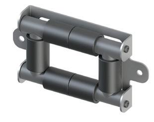
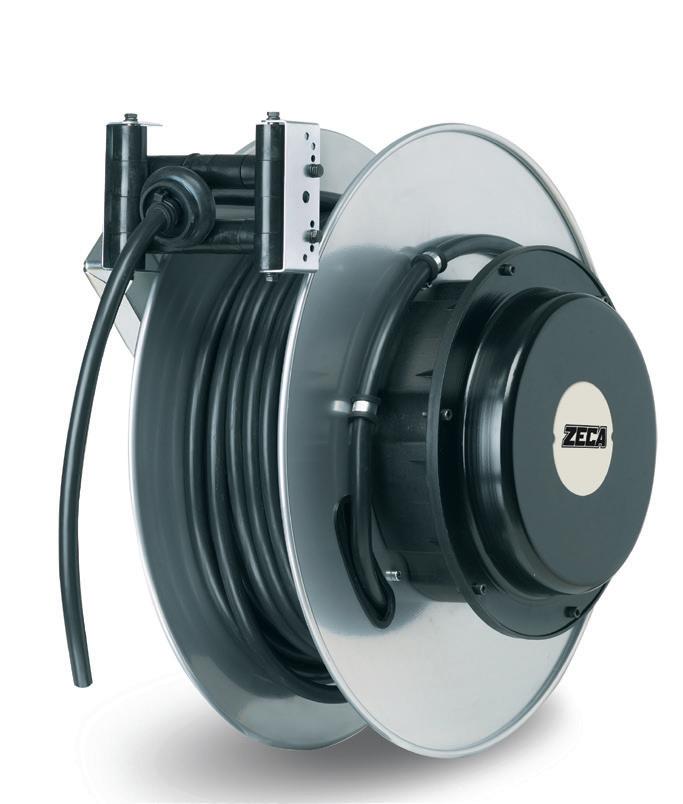
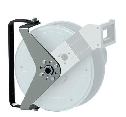
• Epoxy-painted and technopolymer steel case.
• Collectors with power: 20-50-100 A.
• Steel springs suitable to grant a long life.
• Delivered with cable H05VV-F and H07RN-F or without cable.
• Suitable to recoil cables from 1 to 12 conductors
• Working temperature: -5°C/+50°C.
• Max. recoiling speed: 30 m./minute.
• Collector insulating power 2,5 Kv.
Those reels are usually supplied without bracket, without roller cable guide and without ratchet. Those articles can be bought separately, see p.22.
Cable reel suitable for the installation according to methods 1, 2, 3, 7 at page 23.
• Ausführung in heisslackiertem Stahl und Kunststoff.
• Seitlicher Befestigungsflansch aus Aluminium.
• Leitern mit Reichweite von 20 – 50 – 100A
• Stahlfedern mit langem Lebensdauer
• Komplett geliefert mit Kabel H05 VV-F und H07 RN-F, oder ohne Kabel
• Geeignet zum Aufrollen von Kabel von 1 bis 12 Leitern
• Umgebungstemperatur: -5°C / +45°C
• Maximale Aufrollgeschwindigkeit 30 m pro Minute
• Schleifring Isolierungspannung 2,5 KV
Diese Aufroller werden ohne Befestigungsvorrichtung, ohne Rollenkabelführungsöffnung und ohne Zahnarretierung geliefert.
Diese Artikeln können separat bestellt werden, siehe Seite 22.
20
DOWNLOAD TECHNICAL DATASHEET ON ZECA.IT EN61316 EN 61242 EN 60335-1 2014/35/UE 2006/42/UE 2011/65/UE
TECHNICAL FEATURES TECHNISCHE MERKMALE ■ EN ■ DE 1400 1400 SERIES SERIES
Kabelaufroller geeignet für anwendungen laut Abbildungen 1, 2, 3, 7 auf Seite 23.
IP65
21 Number of conductors Conductor crosssections (mm2) Collector capacity (A) Cable length (m) ART. with cable ART. without cable KW (20°C) KW (20°C) Cable type Cable mm Ø Space occupied A 1 x 16 50 22 1420 1470 50 A PVC 8 330 25 100 20 1421 1471 100 A 10 3 G 2.5 20 22 1428 1476 230V 2.0 230V 3.5 PVC 10 330 20 1428 RNF RUBBER 11.5 25 1429 PVC 8.5 4 50 17 1430 1481 3.0 5.0 PVC 12.5 330 4 G 1.5 20 22 1432 RNF 1478 400 V 3F+T 4.0 400 V 3F+T 6.0 RUBBER 10.5 330 2.5 20 20 1434 7.0 10.0 PVC 11 330 17 1434 RNF 1479 RUBBER 12.5 50 20 1435 1480 PVC 11 17 1435 RNF 1481 RUBBER 12.5 4 50 14 1436 11.0 15.0 PVC 14 330 12 1436 RNF RUBBER 15 6 50 10 1438 RNF 17.0 22.0 RUBBER 17 330 5 G 1.5 20 20 1440 1483 400 V 3F+T+N 4.0 400 V 3F+T+N 6.0 PVC 9.5 330 17 1440 RNF 1484 RUBBER 12 2.5 20 17 1442 7.0 10.0 PVC 12.5 330 14 1442 RNF RUBBER 13.5 50 17 1443 1485 PVC 12.5 14 1443 RNF RUBBER 13.5 4 50 10 1444 RNF 11.0 15.0 RUBBER 16.5 330 8 x 1 20 20 1450 1487 3 A PVC 10 330 1.5 17 1452 1488 4.5 A 11.5 2.5 14 1454 7.5 A 14 12 x 1 20 17 1460 1490 3 A PVC 12.50 380 1.5 14 1462 4.5 A 13 2.5 10 1464 7.5 A 17.5 dimensions 1400
1400 SERIES
OPTIONAL ACCESSORIES
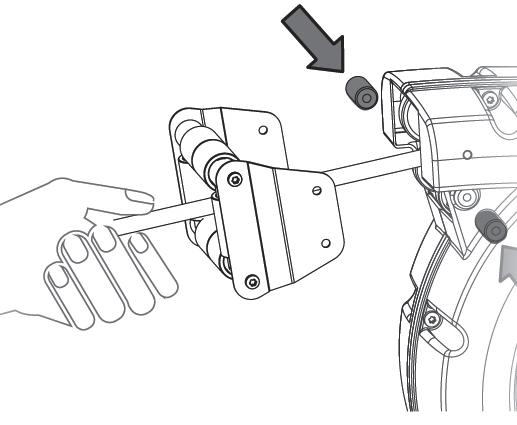
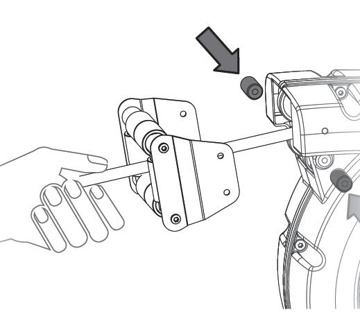
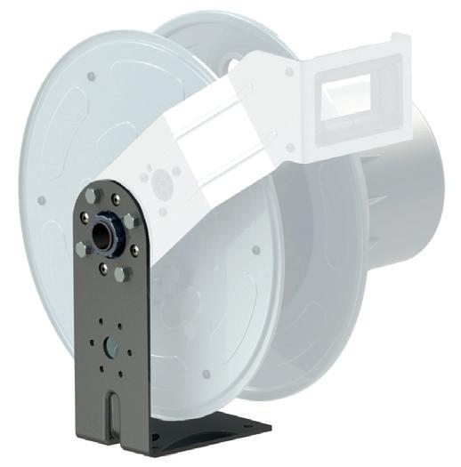
■ SWIVELLING BRACKET ART. 1401
Suitable only if the cable reel is manually used. To be installed with arm with roller cable guide art. 1406.
Diese Befestigungsvorrichtung ist geeignet nur wenn der Kabelaufroller manuell betätigt wird. Mit dem Arm mit Rollenkabelführungsöffnung art. 1406 kombinieren.
■ FIXED BRACKET ART. 1403
For wall, floor or ceiling fastening. To be installed with arm with roller cable guide 1406.

Zur Befestigung an Wand, Fußboden oder Decke. Mit dem Arm mit ollenkabelführungsöffnung art. 1406 kombinieren.
■ A RM WITH ROLLER CABLE ART.1406
Complete with ratchet.
Komplett mit Zahnarretierung
22 20+A 220 360 220 10,5 251 195 105 55 65° 35° 20+A M25x1,5 40 220 360 195 45 105 M25x1,5 40 220 360 195 45 105
1400
220 360 220 10,5 251 195 105 55 65° 35° 1400 SERIES ALL OPTIONALS ARE DELIVERED UNASSEMBLED ALLE OPTIONALS WERDEN UNMONTIERT GELIEFERT
• For correct operation of the cable reels, it is necessary to take into account how they will be installed and how they will have to work
• The cable or hose must always enter centrally as to the reel outlet with no sharp edges, and without scraping against walls or edges.
• These cable reels are to be considered components of a complex whole. Consider a suitable amperometric protection at the top of the reel considering the most unfavourable condition, viz, with cable completely wound. This protection must interrupt all the phases, but not earth contact in case of anomaly or extra electrical input. Unipolar models are suitable for earthing.
• Um die gute Betriebsfähigkeit der Kabelaufroller zu erzielen, ist es unentbehrlich sowohl die Installationsart als auch die Arbeitweise in Betracht zu ziehen
• Das Kabel oder der Schlauch muß immer mittig bezüglich der Kabelführungsöffnung einlaufen, ohne an scharfen Kanten und Wänden zu streifen.
• Diese Aufroller sind als Teil eines Gesamtkomplexes zu betrachten. Es ist erforderlich, einen passenden Amper-Schutz stromauf des Aufrollers vorzusehen, welches die schwierigste Bedienung in Betracht zieht, d.h. mit komplett aufgerolltem Kabel. Dieser Schutz muss alle Phasen unterbrechen, außer die Erdung. Die einpoligen Modelle sind für Erdung geeignet.
methods
23
INSTALLATIONSHINWEISEN FÜR AUFROLLER REEL INSTALLATION
Manual use Cable reel on mobile application Cable reel on mobile application, 2 directions uncoiling Cable reel on mobile application, 2 directions uncoiling Cable reel on stationary application Vertical uncoiling Vertical uncoiling Cable reel on stationary application 1 2 3 4 5 7 8 6 Stationary application Mobile application Mobile application Mobile application Mobile application Stationary applicaation Stationary application
installation
REEL INSTALLATION METHOD
METHOD
Reel
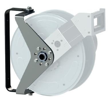
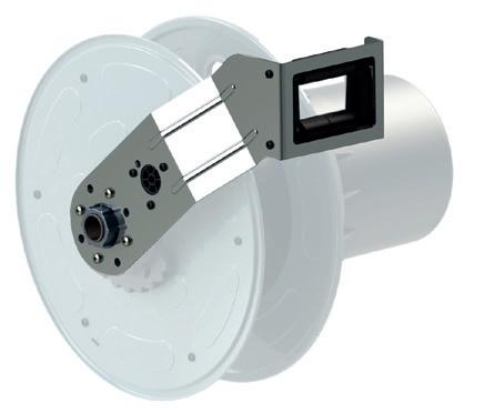
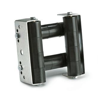
■ DE TECHNICAL FEATURES TECHNISCHE MERKMALE
• Painted aluminium and steel case;
• Side fastening aluminium bracket;
• Roller cable-guide and ratchet delivered only for the models shown in the table (these cable reels are delivered with disconnected ratchet, and it can be easily inserted by user before the installation);
• Collectors with power: 32-60-100 A;
• Steel springs suitable to grant the optimum cable traction ad a long life;
• Protection degree IP65;
• Delivered with cable H05VV-F, H07RN-F, or without cable;
• The reels delivered by us with cable are equipped with cable fastening socks suitable to the installed cable;
• Suitable to recoil cables from 1 to 24 conductors, with max. length 53 m.,
• Delivered with 2,5 m. incoming cable;
• Working temperature: -5°C/+50°C;
• Max. recoiling speed: 30 m./minute;
• Collector insulating power 2,5 KV.
• Ausführung in heisslackiertem Aluminium und Stahl;
• Seitlicher Befestigungs-Flansch aus Aluminium;
• Nur für die in der Tabelle gegeben Modelle mit Öffnung der Kabelführung mit Rollen und Zahnarretierung geliefert (die Zahnarretierung wird ausgeschaltet geliefert und ist von dem Benutzer leicht einzuschaltenvor Inbetriebnahme);
• Leitern mit Reichweite von 32-60-100 A;
• Stahlfedern, die optimalen Zug des Kabels garantieren und eine lange Lebensdauer;
• Schutzart IP65;
• Komplett geliefert mit Kabel H05VV-F, H07RN-F, oder ohne Kabel;
• Die Aufroller (von uns mit Kabel ausgerüstet) werden mit geeignetem Überzug für Kabelbefestigung für die installierten Kabel geliefert;
• Geeignet zum Aufrollen von Kabel von 1 bis 24 Leitern, mit maximaler Länge von 53 m.;
• Geliefert mit Zuleitung 2,5 m.;
• Umgebungstemperatur: -5°C/+50°C;
• Maximale Aufrollgeschwindigkeit: 30 m pro Minute;
• Schleifring Isolierungspannung 2,5 Kv.
24 DOWNLOAD TECHNICAL DATASHEET ON ZECA.IT IP65 EN61316 EN 61242 EN 60335-1 2014/35/UE 2006/42/UE 2011/65/UE 1700 SERIES
■ EN
1700 SERIES
The type 2 cable reels are supplied without:
• cable guide
• bracket
• no ratched. These accessories can be purchased separately, see page 28.
Die Kabeltrommeln vom Typ 2 werden ohne Folgendes geliefert:
• Kabelführungsöffnung
• Bügel
• ohne Arretierung.
Dieses Zubehör kann separat erworben werden, siehe Seite 28.
■ EN Before purchasing, first check the table on page 26-27 to find out whether or not they can be installed
■ DE Prüfen Sie vor dem Kauf, ob sie auf dem Tisch installiert werden können - siehe Seite 26-27
25
1700 type 1
1700 type 2
TYPE 1 CABLE REEL TYPE 2 CABLE REEL dimensions
dimensions
dimensions
1700 SERIES
EN ■ DE
■
26 26 Number of conductors Conductor cross-section (mm 2 ) Cable length(m) ARTICLE Collector capacity(A) Type of Cable type Cable diameter Ø KW KW Optional accessories Dimensions Installation 1-2-3-7 (page 23) All installations (page 23) 1701 1702 1703 1704 1706 1707 1708 A B C 1 x 16 32 1711 60 1 PVC 8 440 160 365 25 32 1712 100 1 PVC 10 440 160 365 42 170125/42 1 3 G 2.5 31 1717 32 1 PVC 10 230V 2.0 230V 3.5 440 160 365 1717 RNF 1 RUBBER 11.5 41 1718 1 PVC 10 1718 RNF 1 RUBBER 11.5 4 G 2.5 31 1722 32 1 PVC 11 400V 3F+T 7.0 400V 3F+T 10.0 440 160 365 1722 RNF 1 RUBBER 12.5 41 1723 1 PVC 11 6.0 8.5 1723 RNF 1 RUBBER 12.5 550 55 1724 2 PVC 11 440 190 395 1724 RNF 2 RUBBER 12.5 550 4 22 1726 32 1 PVC 14 11.0 15.0 440 160 365 1726 RNF 1 RUBBER 15 1727 60 1 PVC 14 410 1727 RNF 1 RUBBER 15 26 1728 32 1 PVC 14 440 160 365 1728 RNF 1 RUBBER 15 1729 60 1 PVC 14 410 1729 RNF 1 RUBBER 15 31 1730 32 1 PVC 14 440 160 365 1730 RNF 1 RUBBER 15 550 1731 60 1 PVC 14 440 410 1731 RNF 1 RUBBER 15 550 45 1732 32 2 PVC 14 10.0 13.5 550 190 395 1732 RNF 2 RUBBER 15 1733 60 2 PVC 14 440 1733 RNF 2 RUBBER 15 6 17 1735 60 1 PVC 17 17.0 22.0 440 160 410 1735 RNF 1 RUBBER 1736 100 1 PVC 1736 RNF 1 RUBBER 26 1737 60 1 PVC 550 160 410 1737 RNF 1 RUBBER 1738 100 1 PVC 1738 RNF 1 RUBBER 40 1739 60 2 PVC 550 190 440 1739 RNF 2 RUBBER 1740 100 2 PVC 1740 RNF 2 RUBBER 10 16 1742 60 2 PVC 22 25.0 30.0 550 160 410 1742 RNF 2 RUBBER 1743 100 2 PVC 1743 RNF 2 RUBBER 25 1744 60 2 PVC 550 190 440 1744 RNF 2 RUBBER 1745 100 2 PVC 1745 RNF 2 RUBBER 40 1746 60 2 PVC 650 190 440 1746 RNF 2 RUBBER 1747 100 2 PVC 1747 RNF 2 RUBBER 16 16 1749 100 2 PVC 24 35.0 40.0 550 160 410 170416/16T 2 TPE 21 30 1750 2 PVC 24 650 190 440 170416/30T 2 TPE 21 1700 SERIES INCLUDED OPTIONAL ACCESSORIES NO
no.
All models are also available without cable; add “SC” to the article
27 Number of conductors Conductor cross-section (mm 2 ) Cable length(m) ARTICLE Collector capacity(A) Type of Cable type Cable diameter Ø KW KW Optional accessories Dimensions Installation 1-2-3-7 (page 23) All installations (page 23) 1701 1702 1703 1704 1706 1707 1708 A B C 5 G 2.5 22 1752 32 1 PVC 12.5 400V 3F+T+N 7.0 400V 3F+T+N 10 440 160 365 1752 RNF 1 RUBBER 13.5 26 1753 1 PVC 12.5 1753 RNF 1 RUBBER 13.5 31 1754 1 PVC 12.5 440 160 365 1754 RNF 1 RUBBER 13.5 550 55 1755 2 PVC 12.5 6.0 8.5 550 190 395 1755 RNF 2 RUBBER 13.5 6 17 1757 60 1 PVC 17 17.0 22.0 440 160 410 1757 RNF 1 RUBBER 18.5 1758 100 1 PVC 17 1758 RNF 1 RUBBER 18.5 26 1759 60 1 PVC 17 550 160 410 1759 RNF 1 RUBBER 18.5 1760 100 1 PVC 17 1760 RNF 1 RUBBER 18.5 40 1761 60 2 PVC 17 550 190 440 1761 RNF 2 RUBBER 18.5 1762 100 2 PVC 17 1762 RNF 2 RUBBER 18.5 16 15 170516/15 100 2 PVC 24 35.0 40.0 550 160 410 170516/15T 2 TPE 23 30 170516/30 2 TPE 24 650 190 440 170516/30T 2 TPE 23 8 x 1.5 22 1764 16 1 PVC 11.5 4.5 440 160 410 40 1765 1 550 2.5 17 1766 32 1 PVC 14 7.5 440 160 410 26 1767 1 550 40 1768 2 190 440 55 1769 2 10 x 1.5 17 1771 16 1 PVC 15.5 4.5 440 160 410 26 1772 1 550 55 1773 2 190 440 12 x 1.5 17 1775 16 1 PVC 13 4.5 440 160 480 26 1776 1 550 40 171215/40 1 55 1777 2 190 510 2.5 17 171225/17 32 1 PVC 17.5 7.5 440 160 480 26 171225/26 1 550 40 171225/40 2 190 510 16 x 1 32 1778 16 1 PVC 15 3.0 550 190 510 1.5 18 1779 16 1 PVC 17.5 4.5 440 160 480 26 1780 1 550 40 1781 2 190 510 2.5 18 1782 32 1 PVC 23.5 7.5 550 160 480 26 1783 1 190 510 40 1784 2 650 18 G 1.5 17 171815/17 16 1 PVC 17.5 4.5 440 160 500 26 171815/26 1 550 40 171815/40 2 190 530 2.5 17 171825/17 32 1 PVC 23.5 7.5 550 160 500 26 171825/26 1 190 530 40 171825/40 2 650 25 G 1.5 16 1787 16 1 PVC 19.5 4.5 550 160 580 25 1788 2 190 610 40 1789 2 650 2.5 15 172525/15T 32 2 TPE 24.5 7.5 550 160 580 25 172525/25T 2 650 190 610
Alle Modelle sind auch ohne Schlauch verfügbar; “SC” zu den Art. Nummern beifügen.
1700 SERIES
OPTIONAL ACCESSORIES
■ 1701 ■ 1702
SWIVELLING BRACKET
THIS OPTIONAL IS DELIVERED UNASSEMBLED
Check on the table at pages 160 and 161 the models on which the optional bracket can be installed. This bracket is suitable only if the cable reel is manually used.
BEFESTIGUNGSVORRICHTUNG
DIESE OPTION WIRD DEMONTIERT GELIEFERT
In der Tabelle auf Seite 160 und 161 sind die Modelle aufgeführt, für die diese optionale Vorrichtung geeignet ist. Diese Befestigungsvorrichtung ist geeignet nur wenn der Kabelaufroller manuell betätigt wird.
SAFETY RETURN SYSTEM
Safety Return allows the slowed down rewinding of the cables, avoiding dangerous blowbacks in case the operator loses his grip on the cable. Safety Return is an optional braking device. For entire Zeca 1700 series. It is possible to install this optional only during the assembly of the cable reel, so this part cannot be bought separately.
VERLANGSAMUMG VORRICHTUNG
Die Safety Return verlangsamt die versehentliche rasche und plötzliche Aufwicklung des Kabels, und vermeidet gefährliche Rückschläge für den Fall, dass das Kabel aus der Hand des Bedieners gerät. Safety Return ist eine optionale Bremssteuerung für die Zeca 1700 Serie. Diese Optional kann nur während der Montage des Kabelaufrolles montiert werden.
dimensions
28 1700 SERIES
ART. 1706 - 1707
ART. 1707 - 1707/650
Arm with roller cable guide and ratchet. Kabel Arm mitollenkabelführungsöffnung and Zahnarretierung..
■ 1703 ■ 1704 - 1708
FIXED BRACKET
THIS OPTIONAL IS DELIVERED UNASSEMBLED
For wall, floor or ceiling fastening (the reel is standard delivered for a side fastening). Check on the table at pages 160 the models on which the optional bracket can be installed.
FESTE BEFESTIGUNGSVORRICHTUNG
DIESE OPTION WIRD DEMONTIERT GELIEFERT

Zur Befestigung an Wand, Fussboden oder Decke. In der Tabelle auf Seite 160 sind die Modelle aufgeführt, für die diese optionale Vorrichtung geeignet ist.
Installation methods with optional bracket art. 1703. Befestigungsmöglichkeit des Aufrollers mit optionaler Befestigungsvorrichtung Nr. 1703.
SWIVELLING ARM

For installation with middle travel feeding. Installation methods 3,4 at page 157. Impossible to install the swivelling arm with other optionals. Check on the table at pages 160 and 161 the models on which the optional arm can be installed. It is possible to install this optional only during the assembly of the cable reel, so this part cannot be bought separately.
CAUTION: It is NOT possible to install the ratchet on reels with swivelling arm art. 1704 - 1708
SCHWENKBARER ARM
Für Anwendungen mit Versorgung am Mittelauf. Abb. 3,4 auf Seite 157.Anwendung des schwenkbaren Arms mit anderen Optionals unmöglich. In der Tabelle auf Seite 160 und 161 sind die Modelle aufgeführt, für die diese optionale Vorrichtung geeignet ist. Dieses Optional kann nur während der Montage des Kabelaufrollers montiert werden.
ACHTUNG: Es ist NICHT möglich die Arretierung auf Aufroller mit schwenkbaren Arm Art. 1704 - 1708 zu montieren.
29 1800 SERIES
■ ART. 1704 ■ ART. 1708 dimensions
TECHNICAL FEATURES
• Aluminium and steel case painted in epoxy resin
• Side fastening aluminium bracket
• Steel springs suitable to grant optimum cable traction and a long life
• Available also without cable
• The reels are delivered by us with cable fastening socks suitable to the installed cable
• Delivered with 2,5m incoming cable
• Working temperature: -5C/+50C
• Max. Recoiling speed 30m/min
• Collector insulating power 2,5KV
• Ausführung in heisslackiertem Aluminium und Stahl;
• Seitlicher Befestigungs-Flansch aus Aluminium;
• Stahlfedern, die optimalen Zug des Kabels garantieren und eine lange Lebensdauer;
• Geliefert auch ohne Kabel;
• Die Aufroller (von uns mit Kabel ausgerüstet) werden mit geeignetem Überzug für Kabelbefestigung für die installierten Kabel geliefert;
• Geliefert mit Zuleitung 2,5 m.;
• Umgebungstemperatur: -5°C/+50°C;
• Maximale Aufrollgeschwindigkeit: 30 m pro Minute;
• Schleifring Isolierungspannung 2,5 KV
30 1800 SERIES DOWNLOAD TECHNICAL DATASHEET ON ZECA.IT
IP65
TECHNISCHE MERKMALE ■ EN ■ DE 1800 SERIES
31 1800 SERIES Number of conductors Conductor crosssections Cable length (m) ART. Collector capacity (A) Cable type Cable diameter mm Ø KW (20°C) KW (20°C) C 4G 6 50 180406/50RA 60 RUBBER 17 400V 3F+T 17 400V 3F+T 22 470 180406/50RB 100 10 50 180410/50R 100 RUBBER 22 25 30 180410/50T TPE 17 16 40 180416/40 100 PVC 21 35 40 180416/40T TPE 25 40 180425/40T 100 TPE 25 45 50 5G 6 50 180506/50RA 60 RUBBER 18.5 400V 3F+T+N 17 400V 3F+T+N 22 470 180506/50RB 100 10 50 180510/50 100 PVC 20 25 30 180510/50T TPE 19 16 40 180516/40 100 PVC 24 35 40 180516/40T TPE 23 12x 2.5 50 181225/50 32 PVC 17.5 7.5 A 540 181225/50P PUR 18x 2.5 50 181825/50 32 PVC 23.5 7.5 A 560 181825/50T TPE 23 25x 1.5 50 182515/50 16 PVC 19.5 4.5 A 640 182515/50P PUR 2.5 40 182525/40T 32 TPE 24.5 7.5 A ONLY FOR INSTALLATIONS 2/3/7 (P. 23) dimensions EN61316 EN 61242 EN 60335-1 2014/35/UE 2006/42/UE 2011/65/UE
ACCESSORIES
■ ART. 932
CABLE GUIDE ROLLER WITH BRACKET
Cable guide roller made of shock-resistant plastic material with bracket of galvanized steel sheet.
KABELFÜHRUNGSWALZE MIT STÜTZE
Kabelführungswalze aus stoßfestem Kunststoff mit Bügel aus verzinktem Stahl.
■ ART. 945
FUNNEL-SHAPED CABLE GUIDE OUTLET
Cable guide outlet with structure made of steel sheet, with two series of rollers made of shock-resistant plastic material allowing to unwind the cable in two directions (see 3-4 diagrams on page 23) without causing excessive bending angles, and improving the performance of the cable reel.Maximum Ø cable 35 mm.
TRICHTERKABELFÜHRUNG
Kabelfürung mit Blechstruktur, mit zwei Rollenreihen aus stoßfestem Kunststoff, welche das Abwickeln in zwei Richtungen ermöglichen (siehe Abb. 3, 4 Seite 23), ohne übermäßige Biegungswinkel zu verursachen, wobei ebenfalls die Funktion des Kabelaufrollers verbessert wird. Maxiimaler kabeldurchmesser 35 mm.
■ ART. 949
CABLE-FASTENING SOCKS
The cable fastening socks are manufactured in galvanized steel and are useful for fastening the cable at its end without damaging the internal conductors, is avoiding curling and fast wearing of the cable.
ZIEHSTRUMPF
Der Ziehstrumpf ist aus galvanisiertem Stahl gefertigt und dient dazu, das Kabel an seinem Ende zu befestigen ohne Beschädigung der Innenleiter. So kann sich das Kabel nicht verdrehen und wird daher nicht so schnell beschädigt.
dimensions
dimensions
32
ART Cable external diameter mm Ø A B 949/10 8-10 165 130 949/12 10-13 165 130 949/14 15-18 140 200 949/15 12-16 130 165 949/17 18-22 200 140 949/20 22-28 200 195
A B
■ ART. 951 - 954 - 955 - 957
ROLLER CABLE GUIDE OUTLET
Cable guide outlet with structure made of galvanized steel sheet and nylon rollers. By the repositioning of the rollers it allows to get different dimensions of cable outlet.
KABELFÜHRUNG
Kabelführungsöffnung mit Struktur aus verzinktem Stahlblech und Nylonrollen. Bei der Verschiebung der Rollen erlaubt sie verschiedene Kabelmaße durch die Öffnung zu führen.
FRICTION SPRING
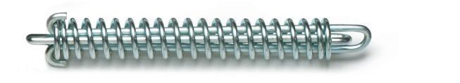
If discontinuous and high tractive efforts are expected, we suggest to insert a friction spring between the cablefastening sock and the anchorage point.
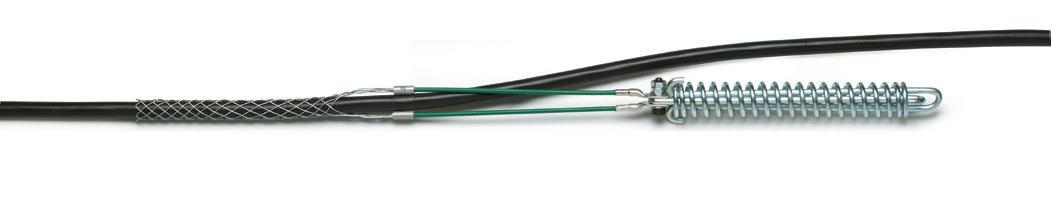
PUFFERFEDER
Sollten höhere und unregelmässige Zugkräfte erforderlich sein, ist es notwendig eine Pufferfeder zwischen dem Überzug für Kabelbefestigung und dem Verankerunspunkt einzusetszen.
REMOVABLE CABLE STOPPERS
33
■ ART. 956 ART A B C 951 15 - 25 - 35 45 - 55 125 55 954 185 115 955 215 145
ART. 951 - 954 - 955
ART. 957
dimensions dimensions
ART ØD (mm) Ød (mm) Ø CABLE - HOSE (mm) 943/0 48 5 5,5 - 6.5 943/1 6 6,5 - 7,5 943/2 7,5 8 - 9 943/3 9 9,5 - 11 943/4 11 11,5 - 13 943/5 13 13,5 - 15 ART ØD (mm) Ød (mm) Ø CABLE - HOSE (mm) 944/1 61 13 13,5 - 15 944/2 14 14,5 - 16 944/3 16 16,5 - 18 944/4 18 18,5 - 20 944/5 25 25 - 26 944/6 11 11,5 - 13 943
944 SERIES Ød ØD TPE ABS CODE ØD (mm) 943/1 48 943/2 48 943/3 48 943/4 48 943/5 48 944/1 61 944/2 61 944/3 61 944/4 61 944/5 61
SERIES
ABNEHMBARE KABELSTOPPER
Supplement to be added to the price of the cable for any requested variation of the cable lengths shown in the tables of 5000, 6000, 4000 and 7000 reels (+cable price)
Preisaufschlag für andere verlangte Längen als die Standardlängen wie in den Tabellen der Aufroller Serie 5000, 6000, 4000 und 7000 angegeben (+ Kabel-Preis)
* center element for high tensile stresses
SPECIAL CABLES
■ EN SPECIAL VERY FLEXIBLE CABLES FOR REELS
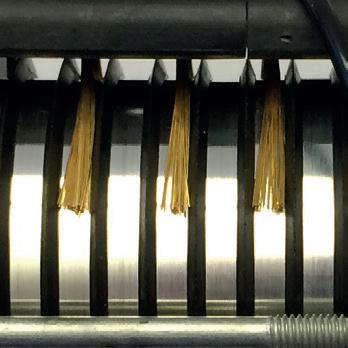
ZECA cables have been expressly designed to be used on cable coilers. Their construction method comes from many years of experience in this field. Cables with 1 and 1,5 mm2 conductors are provided with a heart increasing their resistance to traction. Cables are available in hanks whose max. length is 100 m., H05VV-F cables are conforming to CEI 20-35 standard. (Unipolar cables: H05V-F).
■ DE BESONDERS FLEXIBLE KABEL FÜR KABELAUFROLLER
Die ZECA-Kabel wurden speziell für den Einsatz bei Kabelaufrollern entwickelt. Die Ausführung ist ein Resultat der jahrelangen Erfahrung auf diesem Gebiet. Die Kabel mit Leiter- Querschnitt von 1 mm2 und 1,5 mm2 haben einen Kern, um den Widerstand gegen den Zug zu erhöhen. Diese Kabel werden in Strängen mit maximaler Länge von 100 m geliefert. Sie sind vom Typ H05VV-F und den Normen CEI 20-35 entsprechend (Einpolige Kabel: H05V-F).
34
Number of conductors Conductor cross-section (mm 2 ) Cable type Cable diameter mm Ø ART. 1 X 2.5 PVC Yellow/Green 5.5 1001 6 PVC Yellow/Green 5.5 1002 15 PVC Black 9 1004/N PVC Red 9 1004/R 16 PVC Yellow/Green 8 1004/G-V 25 PVC Black 10 1005/N PVC Red 10 1005/R PVC Yellow/Green 11 1005/G-V 2 X 1 PVC * 6.5 1021 H05 RN-F 6.5 1060 RUBBER 8 1061 1.5 PVC 8 1022 2.5 PVC 9 1009 3 G 1 PVC 6.5 1023 RUBBER 9 1062 1.5 PVC * 7.5 1024 RUBBER 9.5 1063 2.5 PVC 10 1012 RUBBER 11.5 1064 4 G 1 PVC * 7 1025 1.5 PVC * 8.5 1026 RUBBER 10.5 1065 2.5 PVC 11 1016 RUBBER 12.5 1066 4 PVC 14 1017 6 PVC 17 1018 RUBBER 17 1069 10 PVC 22 1019 16 PVC 24 1020 Number of conductors Conductor cross-section (mm 2 ) Cable type Cable diameter mm Ø ART. 5 G 1 PVC * 8 1027 1.5 PVC * 8.5 1028 RUBBER 12 1067 2.5 PVC 12.5 1051 RUBBER 13.5 1068 6 PVC 17.5 1058 RUBBER 18.5 1071 7 X 1 PVC * 9 1031 1.5 PVC * 10.5 1032 8 X 1 PVC * 10 1033 1.5 PVC * 11.5 1034 2.5 PVC 14 1041 12 G 0.5 TPE 9,5 1070 1 PVC 12.5 1037 1.5 PVC 13 1038 2.5 PVC 17.5 1050 18 G 1 PVC 15 1072 1.5 PVC 17.5 1073 2.5 PVC 23.5 1074 25 G 1.5 PVC 19.5 1044 2.5 TPE 24.5 1076
ART. 950
SPECIAL CABLES
SPECIAL SLIP RING FOR SIGNAL TRANSMISSION

PROCESSCHECKS
We guarantee maximum quality and continuity in the signal transmission thanks to Zeca’s special DataFlux collector.
Dank des speziellen DataFluxKollektors von Zeca können wir höchste Qualität und Kontinuität bei der Signalübertragung garantieren.
MEDICALSYSTEMS.
AND SECONDARY P GNIGAKCA
ETHERNET NETWORKS
(mod. CAT 5E and CAT 6 also suitable for Gigabit networks)
ETHERNET-NETZWERKE
(Mod. KAT 5E und KAT 6 auch für Gigabit-Netzwerke geeignet)
BUS FOR AUTOMATION (specific cables available on request).
BUS FÜR AUTOMATISIERUNG (spezielle Kabel auf Anfrage erhältlich).

35 DATAFLUX
E S
R O B OT,
S .SMETSY
P R O DUCTIONAND
CE U UPDATE DATAFLUX
DATA FLUX 100%stable connection HCAM I N
FORPRIMARY
MEASURING AND INSPECTION
STANDARD COLLECTOR DATAFLUX COLLECTOR Contact Number 1 ÷ 25 6/12/24 Material Brass / Phosphor bronze Gold alloy Maximum Capacity 10 A 2 A Maximum Voltage 500V 48V Dielectric Strength 2500Vca at 50/60Hz 500Vca at 60Hz Insulation resistance 1000MΩ 1000MΩ / 500Vdc Noise index 70mΩ 100mΩ / 6Vdc / 50mA Bandwidth 1 kHz 1 GHz
■ STANDARD COLLECTOR ■ DATAFLUX COLLECTOR ■ EN ■ DE
DATAFLUX
COLLECTOR
• 6/12/24 contacts, max capacity 2A, max 48V.
• Gold alloy rings and brushes.
• High reliability and duration.
• Low friction torque.
• Dielectric strength: 500 Vca at 60 Hz.
• Insulation resistance: > 1000 MΩ/ 500 Vcc.
• Noise: < 100 mΩ a 6 Vcc and 50 mA (at 5 rpm).
CABLE
• Outer jacket: mixture In PUR/TPE highly flexible, abrasion/oil/coolers - resistant.
• Silicon-free.
• Halogen-free (following EN 50267-2-1).
• Lead-free (following 2011/65/EU ROHS-II).
• Cores combined in bundles and stranded together around a centre for high tensile stresses with adapted, short pitch lengths and pitch directions, especially lowtorsion structure.
• Usable for mobile laying (reduced radius of curvature).
KOLLEKTOR
• 6/12/24 Spuren, max. Kapazität 2A, max. 48V.
• Ringe und Bürsten aus Goldlegierung.
• Sehr hohe Zuverlässigkeit und Haltbarkeit.
• Sehr geringes Reibungsmoment.
• Dielektrische Festigkeit: 500 Vac bei 60 Hz.
• Isolationswiderstand: > 1000 MΩ/ 500 VDC.
• Lärm: < 100 mΩ bei 6 VDC und 50 mA (bei 5 U/min).
KABEL
• Außenmantel: besonders flexible, abriebfeste, öl- und kühlmittelbeständige PUR/TPE-Verbindung.
• Silikonfrei.
• Halogenfrei (entspricht der EN 50267-2-1).
• Bleifrei (konform mit 2011/65/EU ROHS-II)
• Gebündelte, kurzdrahtige Leiter, die für eine optimale Torsionsfestigkeit optimiert sind.
• Geeignet für die mobile Verlegung (kleiner Biegeradius).
36 DATAFLUX
■ EN ■ DE TECHNICAL FEATURES TECHNISCHE MERKMALE PLASTIC BODY CABLE REEL IP65 67 SERIES IP42 47 SERIES IP42 AL41/71205
BODY
DOWNLOAD TECHNICAL DATASHEET ON ZECA.IT EN 61242 EN 60335-1 2011/65/UE 2006/42/UE
ALUMINIUM
ALUMINIUM BODY
Roller cable-guide for cable reels PR series. Essential for ceiling applications.
Rollen-Kabelführungsoffnung für Serie PR. Unentbehrlich bei Deckenmontage.
37 DATAFLUX 7mm 0,3in 170mm 6,7in 350mm 13,8in R145mm 5,7in 160mm 6,3in 804 2023 7mm 0,3in 170mm 6,7in 350mm 13,8in R145mm 5,7in 160mm 6,3in 804 2023 4000 dimensions Number of conductors Cable length (m) ART. Cable diameter Ø Cable type IGUS code IP (5 x 0.5) C 12 + 1 470505C 7.5 TPE CF10.05.05 42 20 + 2 670505C 65 6 x 0.75 15 + 1 470607 8 TPE CF9.07.07 42 20 + 2 670607 65 (11 x 0.25) C 8 + 1 471102C 9.5 TPE CF10.02.12 42 18 + 2 671102C 65 (11 x 0.5) C 10 + 2 671105C 11.5 TPE CF10.05.12 65 (23 x 0.25) C 6 + 2 672302C 13 TPE CF10.02.24 65 12 x 0.5 9 +1 471205 9.5 TPE CF9.05.12 42 9 +1 AL41/71205 20 + 2 671205 65 24 x 0.5 15 + 2 142405 13 TPE CF9.05.25 65 Number of conductors Cable length (m) ART. Cable diameter Ø Cable type IGUS code IP (4 x (2 x 0.15)) C 11 + 1 4708 LAN* 7.5 PUR CFBUS. PUR.045 42 20 + 2 6708 LAN* 65 SERIE 47 mm 335x310x185 Kg 5,0 1 44 44 SERIE AL41/71205 200 R145 6 130 175 165 200 R145 6 130 175 165 AL dimensions mm 335x310x185 Kg 5,0 1 63 dimensions SERIE 67 mm 400x390x290 Kg 13,0 1 30 ART. 953 OPTIONAL FOR 67 SERIES 10,5mm 0,4in 400mm 15,7in 25 1 mm 9,9in 360mm 14,2in 215mm 8,5in
* CAT6 Cable, CAT5E collector,
TWIN REELS
BATTERIES 100% CHARGED, COMPRESSED AIR ALWAYS AVAILABLE
PROCESSCHECKS
This system is ideal for keeping rescue vehicles powered like those of the fire brigade. The cable ensure the vehicle that the electric part is always powered and the compressed air tanks are always full.
■ EN ■ DE
Dieses System ist ideal für die Stromversorgung von Rettungsfahrzeugen wie z.B. Feuerwehren. Das Kabel ermöglicht es, das Fahrzeug mit Strom zu versorgen und die Drucklufttanks aufzuladen.
CABLE / HOSE FEATURES
Hose material PA
Int. hose diameter 4,00 mm
Ext. hose diameter 6,00 mm
Core insulation PVC
Core identification Brown, black, grey, green/yellow
Outer Jacket PVC
Flame retardant IEC 60332-1
Color Black
Nominal voltage 300 / 500 V (50 Hz)
Testing voltage 2,5 kV
Temperature da -5°C a +70 °C
Bend radius 8 x D
Electrical wire
Hose

38 ENERGY + AIR V4 FIRE BRIGADE
EMERGENCY VEHICLES I NDUSTRIAL MACHINERY I NDUSTRIAL AUTOMATION
TWIN REELS
• Shock resistant plastic external case
• Cable roller guide
• Ratchet stop device every 50 cm
• Double earth contact
• Collector insulating power 2,5KV
• Protection degree IP42
• Working temperature -5°C/+50°C
• Maximum working pressure 15 bar
• Maximum working depression 0,95 bar.
■ DE
TECHNISCHE EIGENSCHAFTEN
• Außengehäuse des Aufrollers aus schlagfestem Kunststoff
• Rollen-Mundstück
• Kabelrücklaufsperre mit Zahnarretierung alle 50 cm. Leicht auszuschalten, falls das Kabel ständig gespannt sein soll.
• Doppelter Erdungskontakt
• Schleifring-Trennspannung 2,5 kV
• Schutzart IP42
• Umgebungstemperatur für den Betrieb: -5°C/+50°C
• · Maximaler Betriebsdruck 15 bar
• · Maximaler Betriebsunterdruck 0,95 bar
■ OPTIONAL ACCESSORIES
ART. CTS 12V - ART. CTS 24V
RETTBOX IN-BUILD PLUG
(Marechall) IP55 1P+N+T 20A 250V AC reel power supply 12V/24V for socket ejection
ART. CTS 12V - ART. CTS 24V
RETTBOX EINBAUSTECKER
(Marechall) IP55 1P+N+T 20A 250V AC Spulenversorgung 12V/24V Für Steckerauswurf
SERIES
39 ENERGY + AIR Number of conductors Conductor sections (mm2) Hose internal diameter Ø length of cable-hose (m) Incoming cable+hose (m) ART. KW (20°) KW (20°) Max V Rettbox socket 4 1,5 4 4 1 4415 CT 1,5 2 500 NO 4 1,5 4 4 1 4415 CTP 1,5 2 500 SI EN 61242 EN 60335-1 2014/35/UE 2011/65/UE 2006/42/UE 4000 7mm 0,3in 170mm 6,7in 350mm 13,8in R145mm 5,7in 160mm 6,3in 804 2023 7mm 0,3in 170mm 6,7in 350mm 13,8in R145mm 5,7in 160mm 6,3in 804 2023 dimensions 4000 mm 335x310x185 Kg 5,0 44 1
TWIN REELS
■ EN
REEL FEATURES
SEE PAGE 12
• Shock resistant plastic external case
• Cable roller guide
• Ratchet stop device every 50 cm
• Double earth contact
• Collector insulating power 2,5KV
• Protection degree IP42
• Working temperature -5°C/+50°C
• Maximum working pressure 15 bar
• Maximum working depression 0,95 bar.
• Außengehäuse des Aufrollers aus schlagfestem Kunststoff
• Rollen-Mundstück
• Kabelrücklaufsperre mit Zahnarretierung alle 50 cm
• Doppelter Erdungskontakt
• Schleifring-Trennspannung 2,5 kV
• Schutzart IP42
• Umgebungstemperatur für den Betrieb -5 °C/+50 °C.
• Maximaler Betriebsdruck 15 bar
• Maximaler Betriebsunterdruck 0,95 bar
■ OPTIONAL ACCESSORIES
ART. CTS 12V - ART. CTS 24V
See page / Siehe Seite 37.
Safety Return allows the slowed down rewinding of the cables, avoiding dangerous blowbacks in case the operator loses his grip on the cable. Safety Return is an optional braking device for entire Zeca 7000 series.
Safety Return ermöglicht das langsame
Zurückspulen des Schlauchs und vermeidet gefährliche Rückschläge, falls der Schlauch aus der Hand des Bedieners fällt. Safety Return ist eine optionale Bremsvorrichtung für die gesamte
7000-Serie von Zeca.
40 Number of conductors Conductor sections (mm2) Hose internal diameter Ø length of cable-hose (m) Incoming cable+hose (m) ART. KW (20°) KW (20°) Max V Rettbox socket 4 1 4 7 1.5 7410 CT 1 1.5 500 NO 4 1.5 4 9 1.5 7415 CT 1.5 2 500 NO 4 1.5 4 9 1.5 7415 CTP 1.5 2 500 YES
EN 61242 EN 60335-1 2014/35/UE 2011/65/UE 2006/42/UE 7000 mm 430x400x210 Kg 8,0 - 10,0 20 1
170mm 6,7in R185mm 7,3in 490mm 19,3in 4mm 0,2in 210mm 8,3in 7000/805 VERSIONE 2023 dimensions 7000
TECHNISCHE EIGENSCHAFTEN ■ EN ■ DE SERIES
REEL FEATURES
■ EN ■ DE TWIN REELS ENERGY + AIR NEW QUICK FIT
■ EN
CABLE REEL FEATURES
• Polymer-painted steel case
• Side fastening aluminium bracket
• Long durability steel springs
• Protection degree IP65
• Working temperature: -5°C/+50°C
• Collector insulating power 2,5KV
• Maximum working pressure 15 bar
• Maximum working depression 0,95 bar
■ DE
TECHNISCHE EIGENSCHAFTEN
• Gehäuse aus Stahl mit Epoxy-Lackierung und Polymer-Kunststoff
• Seitlicher Befestigungsflansch aus Aluminium
• Langlebige Stahlfeder
• Schutzart IP65
• Umgebungstemperatur für den Betrieb: -5°C/+50°C
• Schleifring-Trennspannung 2,5 kV
• Maximaler Betriebsdruck 15 bar
• Maximaler Betriebsunterdruck 0,95 bar
■ OPTIONAL ACCESSORIES
ALL OPTIONALS ARE DELIVERED UNASSEMBLED
■ ART. 1401 SWIVELLING BRACKET
Suitable only if the cable reel is manually used. For wall fastening.
For wall, floor or ceiling fastening.
ART. CTS 12V
ART. CTS 24V
See page / Siehe Seite 37.
41 Number of conductors Conductor sections (mm2) Hose internal diameter Ø length of cable-hose (m) Incoming cable+hose (m) ART. KW (20°) KW (20°) Max V Rettbox socket 4 1 4 10 2 1431 CT 1.5 2 500 NO 4 1.5 4 13 2 1432 CT 1.5 2 500 NO 4 1.5 4 13 2 1432 CTP 1.5 2 500 YES
EN 61242 EN 60335-1 2014/35/UE 2011/65/UE 2006/42/UE 1400 mm 40x40x40 Kg 14,0 12 1
IP65
FIXED
SERIES TWIN REELS ENERGY + AIR
■ ART. 1403
BRACKET
1ST: DEGREES OF PROTECTION AGAINST ACCESS TO SOLID FOREIGN OBJECTS
IP TESTS
0x No protection
1x Protected against solid bodies larger than 50 mm (eg.: accidental contact with the hand)
2x Protected against solid bodies larger than 12,5 mm (eg.: finger of the hand)
3x Protected against solid bodies larger than 2,5 mm (tools, wires)
4x Protection against solid bodies larger than 1 mm (fine tools, small wires)
5x Protected against dust (no harmful deposit)
6x Completely protected against dust
2ND FIGURE: DEGREES OF PROTECTION AGAINST INGRESS OF WATER
IP TESTS
x0 No protection
IP CODE: DEGREES OF PROTECTION PROVIDED BY ENCLOSURES - EN60529 IK CODE:
x1 Protected against vertically-falling drops of water (condensation)
x2 Protected against drops of water falling at up to 15° from the vertical
x3 Protected against drops of rainwater at up to 60° from the vertical
x4 Protected against projections of water from all directions
x5 Protected against jets of water from all directions
x6 Completely protected against jets of water of similar force to heavy seas
x7 Protected against the effects of immersion
x8 Protected against effects of prolonged immersion under specified conditions
42
IK TESTS IMPACT ENERGY 01 0,15 J 02 0,20 J 03 0,35 J 04 0,50 J 05 0,70 J IK TESTS IMPACT ENERGY 06 1 J 07 2 J 08 5 J 09 10 J 10 20 J
DEGREES OF IMPACT RESISTANCE 10 cm 150 g 40 cm 250 g 15 cm 250 g 40 cm 1,25 kg 10 cm 200 g 40 cm 0,5 kg 20 cm 250 g 40 cm 2,5 kg 20 cm 350 g 40 cm 5 kg


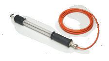


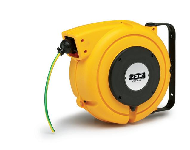
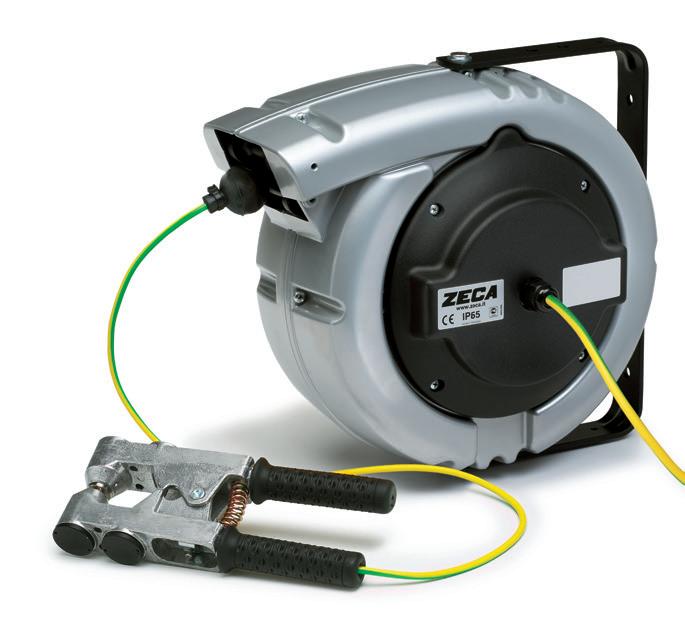
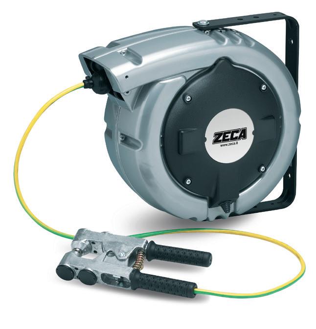
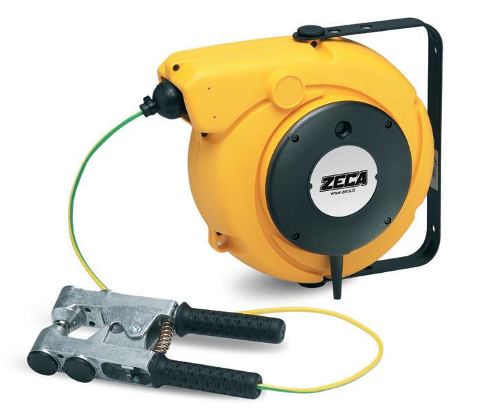
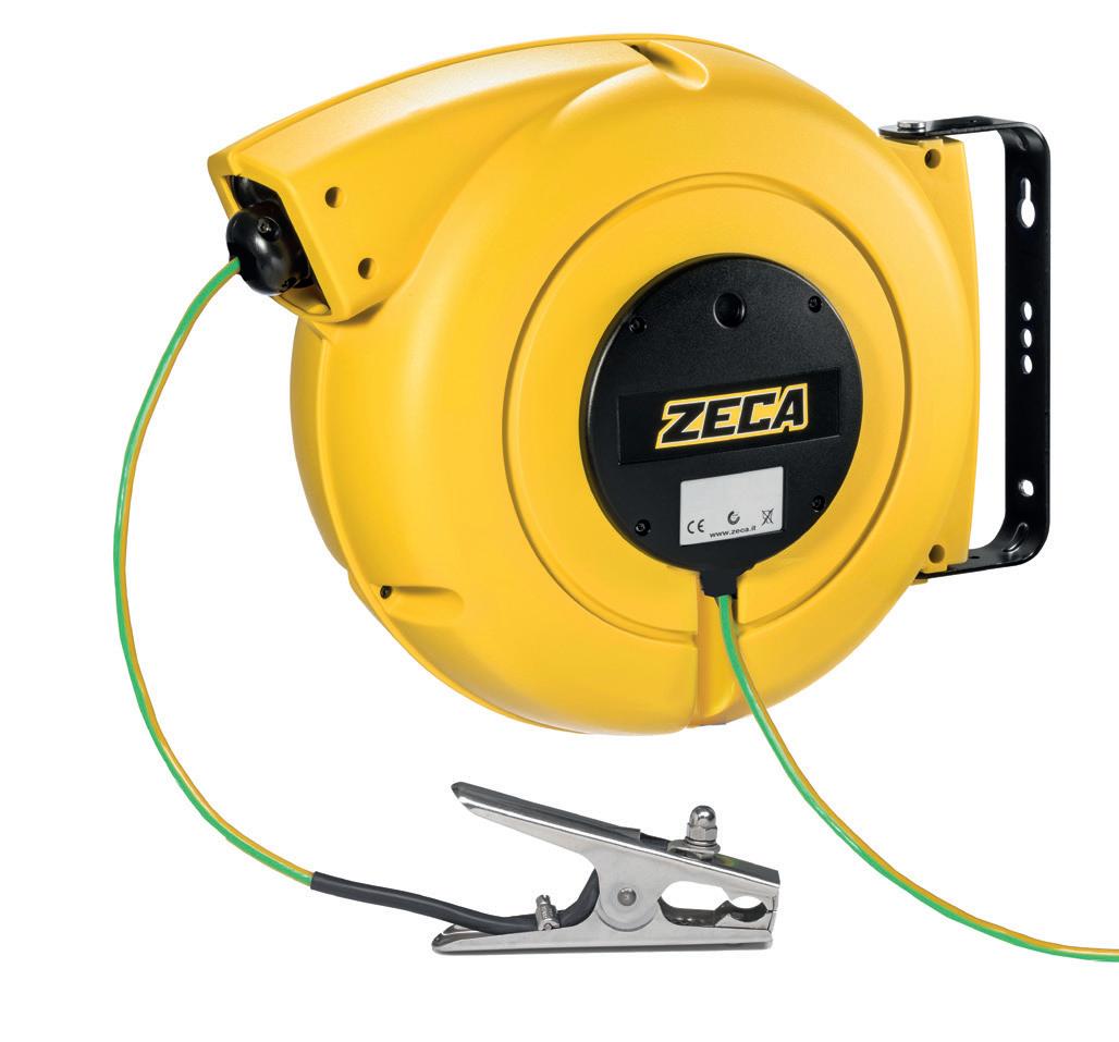
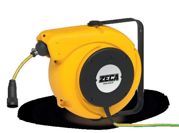
43 Reels for grounding GROUNDING CABLE REELS page 46 GROUNDING CABLE REELS WITH CLAMP page 48 GROUNDING CABLE REEL WITH EXPLOSION-PROOF CLAMP page 50 CABLE REEL FOR GROUNDING 100% ATEX page 51 ATEX PORTABLE LAMP page 52
GROUNDING CABLE REELS
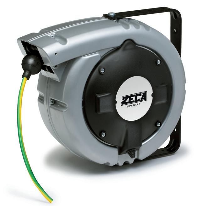
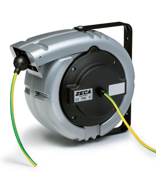
SUITABLE TO ELIMINATE THE ELECTROSTATIC LOADS
STANDARD APPLICATIONS
FIELDS OF USE
Cable reels with grounding are essential when carrying out operations involving the transfer of tanks containing flammable substances in order to avoid dangerous electrostatic charges and work in complete safety. Two installation examples are given on the next page. The choice between the cable reel models must be made by the customer based on where it will be used. The user is responsible for making sure that the model is suitable for their work environment.
ANWENDUNGSBEREICHE
Die Verwendung der Erdungskabeltrommel ist beim Umfüllen von Behältern mit brennbaren Stoffen erforderlich, um gefährliche elektrostatische Aufladungen zu vermeiden und ein sicheres Arbeiten zu gewährleisten. Auf der gegenüberliegenden Seite finden Sie zwei Installationsbeispiele. Die Wahl zwischen den verschiedenen Kabeltrommelmodellen muss vom Kunden je nach Bestimmungszweck getroffen werden.
Es liegt in der Verantwortung des Benutzers zu prüfen, ob das Modell für seine Arbeitsumgebung geeignet ist.
44 GROUNDING CABLE REELS
■
■ EN
DE WAREHOUSES
AVIATION REFINERIES
NAVAL TANKERS
45 GROUNDING CABLE REELS
Figure 1: installation diagram with cable reel mounted on the grounding pole and Clamp connected to the tanker.
Zeichnung 1: Installationsschema mit am Erdungsmast montierter Kabeltrommel und am Tankwagen angeschlossener Klemme.
Figure 2: installation diagram with cable reel mounted on the tanker and Clamp connected to the grounding pole.
■ EN ■ EN ■ DE ■ DE 1 2
Zeichnung 2: Installationsschema mit auf dem Tankwagen montierter Kabeltrommel und an den Erdungsmast angeschlossener Klemme.
GROUNDING
CABLE REELS


ART. 9006
ART. 5836/XF
ART. 5834/XF
ART. 5832/XF
ART. 4106
ART. 4116
ART. 1420
ART. 1421
ART. 6195/PRC/IP65
ART. 6193/PRC/IP65
ART. 7116
ART. 6198/PRC
ART. 6195/PRC
ART. 6193/PRC
ART. 1711
ART. 1712
46
GROUNDING CABLE REELS
QUICK FIT SEE PAGE 12
NEW
CABLE REEL FEATURES
These cable reels are fitted with a single-pole, yellow/green cable, H05 V-F
They are used to eliminate electrostatic charges (e.g. tankers transferring fuel, carbides, flammable materials, etc.).
The choice between the various models must be made by the customer based on where it will be used.
The user is responsible for making sure that the model is suitable for his work environment.
Diese Kabeltrommeln sind mit einem gelb/grünen einadrigen Kabel, H05 V-F, ausgestattet.
Sie dienen dazu, elektrostatische Aufladungen zu beseitigen (z. B. Kraftstofftransporter, Elektrocarbide, brennbare Stoffe usw.).
Die Wahl zwischen den verschiedenen Modellen muss der Kunde je nach dem vorgesehenen Bestimmungsort treffen.
Es liegt in der Verantwortung des Benutzers zu prüfen, ob das Modell für seine Arbeitsumgebung geeignet ist.
47
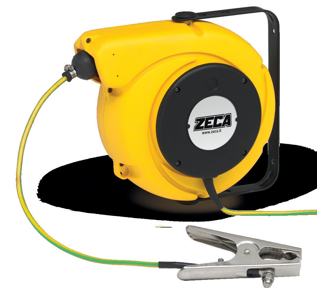
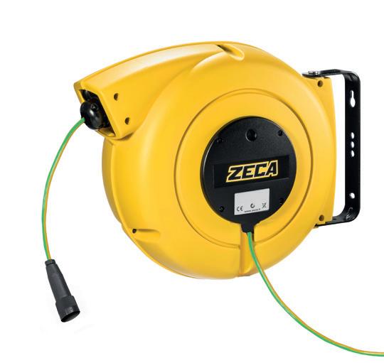
Number of conductors Conductor cross-section (mm2) cable length (m) ART. IP rating Collector capacity (A) Ø cable (mm) Current insulation Cable type 1 x 2,5 15 + 1,5 5836/XF IP42 10 5,5 2,5 KV PVC 28 + 2 6198/PRC 1 x 6 6 + 1 9006 IP42 10 5,5 2,5 KV PVC 12,5 + 1,5 5834/XF 20 15 + 1 4106 22 + 2 6195/PRC/IP65 24 + 2 6195/PRC IP65 1 x 16 8,5 + 1,5 5832/XF IP42 40 8 2,5 KV PVC 10 + 1 4116 15 + 2 6193/PRC 15 + 2 6193/PRC/IP65 IP65 20 + 2 7116 IP42 20 + 2 1420 IP65 50 30 + 2 1711 IP65 60 1 x 25 18 +2 1421 IP65 100 10 2,5 KV PVC 30 + 2 1712 IP65
MERKMALE DER KABELTROMMEL ■ EN ■ DE GROUNDING CABLE REELS
GROUNDING
CABLE REELS WITH CLAMP
ART. 9006
ART. 5836/XF
ART. 5834/XF
ART. 5832/XF
ART. 4106
ART. 4116
ART. 6195/PRC/IP65
ART. 6193/PRC/IP65
ART. 7116
ART. 6198/PRC
ART. 6195/PRC
ART. 6193/PRC
MERKMALE DER KABELTROMMEL ■ EN ■ DE
CABLE REEL FEATURES
These reels are fitted with a single-pole, yellow/green cable, H05 V-F. They are used to eliminate electrostatic charges (e.g. tankers transferring fuel, carbides, flammable materials, etc.).

The choice between the various models must be made by the customer based on where it will be used.
The user is responsible for making sure that the model is suitable for their work environment.
Diese Kabeltrommeln sind mit einem gelb/grünen einadrigen Kabel, H05 V-F, ausgestattet. Sie werden dienen dazu, elektrostatische Aufladungen zu beseitigen (z. B. Tankwagen, Elektrocarbide, brennbare Stoffe usw.). Die Wahl zwischen den verschiedenen Modellen muss der Kunde je nach dem vorgesehenen Bestimmungsort treffen.
Es liegt in der Verantwortung des Benutzers zu prüfen, ob das Modell für seine Arbeitsumgebung geeignet ist.
48
GROUNDING CABLE REELS NEW QUICK FIT SEE PAGE 12
GROUNDING CABLE REELS
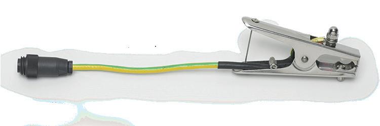
49 Type of Clamp Cable cross-section (Mm²) Length (M) Collector (A) ART. ART. 314 Black Clamp, 150A, length 176 mm 2,5 15+1,5 10 5836/XF/314 28+2 6198/PRC/314 6 6+1 10 9006/314 12,5+1,5 20 5834/XF/314 15+1,5 4106/314 22+2 6195/IP65/314 24+2 6195/PRC/314 16 8+1,5 40 5832/XF/314 10+1 4116/314 15+2 6193/PRC/314 15+2 6193/IP65/314 20+2 7116/314 ART. 925 Black Clamp, 220 A length 255mm 2,5 15+1,5 10 5836/XF/925 28+2 6198/PRC/925 6 6+1 10 9006/925 12,5+1,5 20 5834/XF/925 15+1,5 4106/925 22+2 6195/IP65/925 24+2 6195/PRC/925 16 8+1,5 40 5832/XF/925 10+1 4116/925 15+2 6193/PRC/925 15+2 6193/IP65/925 20+2 7116/925 ART. 926 N Black Clamp, 400A, length 255 mm 2,5 15+1,5 10 5836/XF/926 28+2 6198/PRC/926 6 6+1 10 9006/926 12,5+1,5 20 5834/XF/926 15+1,5 4106/926 22+2 6195/IP65/926 24+2 6195/PRC/926 16 8+1,5 40 5832/XF/926 10+1 4116/926 15+2 6193/PRC/926 15+2 6193/IP65/926 20+2 7116/926
GROUNDING
CABLE REELS WITH EXPLOSION-PROOF CLAMP
ART. 6195/PRC/723
ART. 5834/XF/723
12.5+1.5 m of cable 1x6mm2
22+2 m of cable 1x6mm2
ART. 6195/IP65/723
22+2 m of cable 1x6mm2
Protection degree IP65
THE CABLE REEL IS NOT EXPLOSION PROOF.
• Install the cable reel in a “Safe Area” in accordance with Directive 99/92/EC.
• Single-pole, yellow/green cable 1x6 mm2 H05 V-F
Clamp FEATURES
• Protection mode:
• II 2 G Ex d IIC T6 Gb.
• II 2 D Ex tb IIIC T85°C Db.
• Compliant with standards EN 60079-0: 2009, EN 60079-1: 2007, EN 60529: 1997+A1, EN 60079-31: 2009.
• CESI 03 ATEX 101X approval.
• Compliant with Directive ATEX 94/9/EC.
• Suitable for use in potentially explosive atmospheres with the presence of Group IIC gases and flammable dusts.
• Equipped with a tear-proof opening system.
• Reliable, sturdy, manageable and easy to use.
• Insulation voltage 3 KV.
• Rated current 10A.
• Weight 0.65 Kg.
• Opening (mm) 3 - 20.
• Dimensions (mm) 250 x 110 x 35.
• IP 65.
• Ambient temperature: -20°C + 55°C.
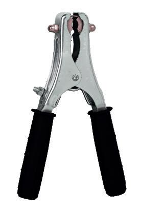
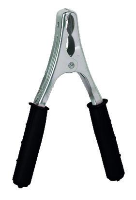
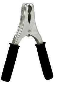
■ EXPLOSION-PROOF CLAMP 723
DIE KABELTROMMEL IST NICHT EXPLOSIONSGESCHÜTZT.
• Installieren Sie die Kabeltrommel in einer „sicheren Zone“ gemäß der Richtlinie 99/92/EG.
• Einadriges Kabel 1x6 mm2 H05 V-F gelb/grün.
EIGENSCHAFTEN ZANGE
• Schutzart:
• II 2 G Ex d IIC T6 Gb.
• II 2 D Ex tb IIIC T85 °C Db.
• Entspricht der Norm EN 60079-0: 2009, EN 60079-1: 2007, EN 60529: 1997+A1, EN 60079-31: 2009.
• Zulassung CESI 03 ATEX 101X.
• In Übereinstimmung mit der ATEX-Richtlinie 94/9/EG.
• Geeignet für den Einsatz in explosionsgefährdeten Bereichen, in denen Gase der Gruppe IIC und brennbare Stäube vorhanden sind.
• Ausgestattet mit einem reißfesten Wiederöffnungssystem.
• Zuverlässig, robust, handlich und einfach zu bedienen.
• Isolationsspannung 3 kV.
• Nennstrom 10 A.
• Gewicht 0,65 kg.
• Öffnung (mm) 3 - 20.
• Abmessungen (mm) 250 x 110 x 35.
• IP 65.
• Umgebungstemperatur: -20 °C + 55 °C.
ART 723/25 Explosion proof Clamp with 25m yellow-green cable, H05 V-F 1x6mm2
ART 723/14,5 Explosion proof Clamp with 14,5m yellow-green cable, H05 V-F 1x6mm2
ART 723/25 Explosionsgeschützte Zange mit 25 m Kabel 1x6 mm2 G-V H05 V-F. ART 723/14,5 Explosionsgeschützte Zange mit 14,5 m Kabel 1x6 mm2 G-V
50
TECHNICAL DATASHEET ON ZECA.IT
DOWNLOAD
■ EN ■ DE TECHNICAL FEATURES TECHNISCHE MERKMALE
EXPLOSION PROOF CLAMP
ATEX GROUNDING CABLE REELS WITH CLAMP
■ EN ■ DE
ZECA presents a series of ATEX products specifically designed for use in environments at risk of explosions.
For each model, you will find the main specifications; additional certificates and features are available on request from the technical department. The installation of all ATEX equipment must be carried out after checking the regulations in force in the area of installation. Whoever certifies the electrical installation is responsible for selecting the product with the correct technical features.
ZECA präsentiert eine Reihe von ATEX-Produkten, die speziell für den Einsatz in explosionsgefährdeten Umgebungen entwickelt wurden.
Für jedes Modell sind die wichtigsten Informationen angegeben, weitere Zertifizierungen und Eigenschaften sind auf Anfrage bei der technischen Abteilung erhältlich. Alle ATEXGeräte dürfen nur nach vorheriger Prüfung der am Installationsort geltenden Vorschriften installiert werden.
Die für die Bescheinigung der Ausführung der elektrischen Anlage zuständige Person ist auch für die Wahl des Produkts mit den richtigen technischen Eigenschaften verantwortlich.
CR7K series cable reel including 10 m of cable 1 x 10mm² + Clamp.
Marking according to EC Directive 94/9/EC II 2G / II 2D
EC test certificate type BVS 10 ATEX E 84.
Kabeltrommel Serie CR7K, komplett mit 10 m 1x10 mm² Kabel + Klemme. Kennzeichnung gemäß der EG-Richtlinie 94/9/EG II 2G / II 2D
EG-Baumusterprüfbescheinigung BVS 10 ATEX E 84.
SEE PAGE 12
CRXK series cable reel including 20 m of cable 1 x 10mm² + Clamp.
Marking according to EC Directive
94/9/EC II 2G / II 2D
EC test certificate type
BVS 10 ATEX E 84.
Kabeltrommel Serie CRXK, komplett mit 20 m 1x10 mm² Kabel + Klemme.
Kennzeichnung gemäß der EG-Richtlinie
94/9/EG II 2G / II 2D
EG-Baumusterprüfbescheinigung
BVS 10 ATEX E 84.
51 100% ATEX
100%
ART. 18-32000-110
ART. 18-33000-120
NEW QUICK
FIT
ATEX GROUNDING CABLE REELS
WITH CLAMP AND CONTROL UNIT
ART. 18-22003-010
CR7K series cable reel including 10 m of cable 1x4 mm² + 2x1 mm². Marking according to EC Directive 94/9/EC II 2(1)G Ex ia [ia Ga] IIC T6 Gb EC test certificate type BVS 09 ATEX E 156 X IECEx BVS 10.0024 X
Kabelaufroller Baureihe CR7K mit 10 m Kabel 1x4 mm² + 2x1 mm².
Kennzeichnung gemäß EG-Richtlinie 94/9/EG II 2(1)G Ex ia [ia Ga] IIC T6 Gb
EG-Baumusterprüfbescheinigung BVS 09 ATEX E 156 X IECEx BVS 10.0024 X
ART. 18-23003-020
CRXK series cable reel including 20 m of cable 1x4 mm² + 2x1 mm². Marking according to EC Directive 94/9/EC II 2(1)G Ex ia [ia Ga] IIC T6 Gb EC test certificate type BVS 09 ATEX E 156 X IECEx BVS 10.0024 X
Kabelaufroller Baureihe CRXK mit 20 m Kabel 1x4mm² + 2x1 mm².
Kennzeichnung gemäß EG-Richtlinie 94/9/EG II 2(1)G Ex ia [ia Ga] IIC T6 Gb
EG-Baumusterprüfbescheinigung BVS 09 ATEX E 156 X IECEx BVS 10.0024 X
ART. 18-24003-020
CRXA series cable reel including 20 m of cable 1x4 mm² + 2x1 mm². Marking according to EC Directive 94/9/EC II 2(1)G Ex ia [ia Ga] IIC T6 Gb EC test certificate type BVS 09 ATEX E 156 X IECEx BVS 10.0024 X.
Kabelaufroller Baureihe CRXA mit 20 m Kabel 1x4mm² + 2x1 mm². Kennzeichnung gemäß EG-Richtlinie 94/9/EG II 2(1)G Ex ia [ia Ga] IIC T6 Gb EGBaumusterprüfbescheinigung BVS 09 ATEX E 156 X IECEx BVS 10.0024 X. 5 m langes Eingangskabel
ART. 18-20002-000
Clamp for control unit EAD09 with connector
EAD09 earthing control unit Marking according to EC Directive 94/9/EC II 3(1)G Ex nA nC [ia Ga] IIC T4 Gc EC test certificate type BVS 09 ATEX E 156 X IECEx BVS 10.0024 X EAD09 earthing control unit Marking according to EC Directive 94/9/EC II 3(1)G Ex nA nC [ia Ga] IIC T4 Gc EC test certificate type BVS 09 ATEX E 156 X IECEx BVS 10.0024 X
N.B. the ATEX certificate is onlyvalid for an assembly consisting of a reel + Clamp + control unit.
■
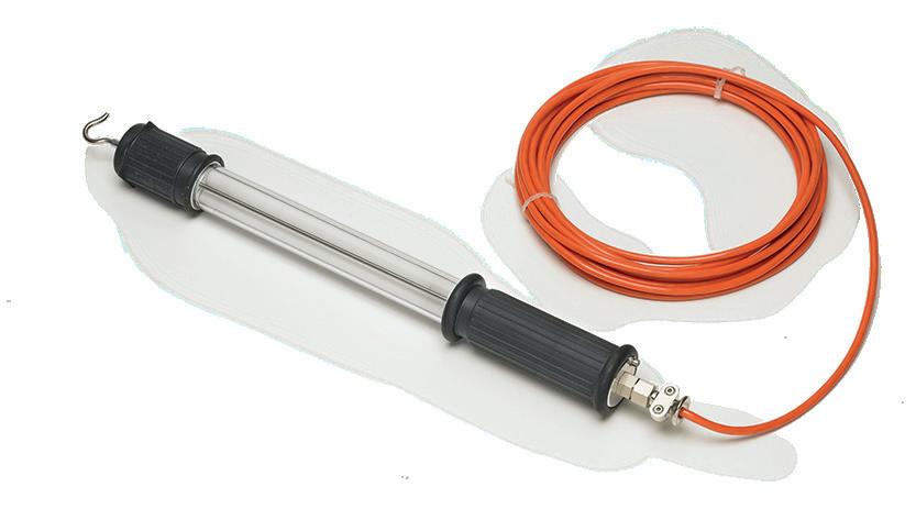
ART. 18-20001-000 ■ ATEX PORTABLE LAMP
EN ■ DE
• Supplied with 10 m of cable.
• No plug or switch.
• Retractable hook
• Category 2G (gas). Protection type: explosion-proof cover Ex d IIC, temperature class T5.
• Lieferung mit 10 m Kabel.
• Ohne Stecker und ohne Schalter.
• · Austauschbare
Leuchtstofflampe 2x8 W.
• Mit drehbarem Aufhängehaken
ART. 77-HL43LED-24 Lamp 24Vac/dc power supply
ART. 77-HL43LED-230
10W LED lamp 230Vac power supply
• Category 2D (dust). Protection type: cover Ex D A21 IP68, maximum surface temperature 95°C.
• Working temperature -20°C +40°C.
• BVS 07 ATEX E 164 X.
• IECEx BVS 08.0014 X.
• Kategorie 2G (Gas). Art des Schutzes: explosionsgeschütztes Gehäuse Ex d IIC, Temperaturklasse T5.
• Kategorie 2D (Staub). Art des Schutzes: Gehäuse Ex tD A21 IP68, maximale Oberflächentemperatur 95 °C. Betriebstemperatur -20°C +40°C.
• · BVS 07 ATEX E 164 X.
52
■ EN ■ EN ■ EN ■ EN ■ DE ■ DE ■ DE
DE
■
• · IECEx BVS 08.0014 X. 100% ATEX NEW QUICK FIT SEE PAGE 12

53
CABLE REELS FOR ELECTRIC VEHICLES page. 54 CABLE REELS FOR BATTERY CHARGERS page. 58 CABLE REELS FOR DRIVE BATTERY CHARGING page. 59 345mm 13,6in R145mm 5,7in
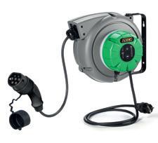
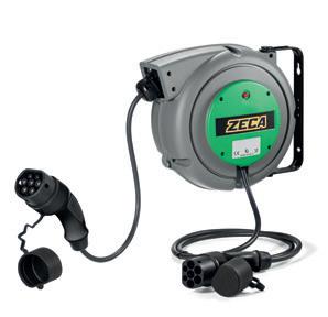
Cable reels for battery chargers
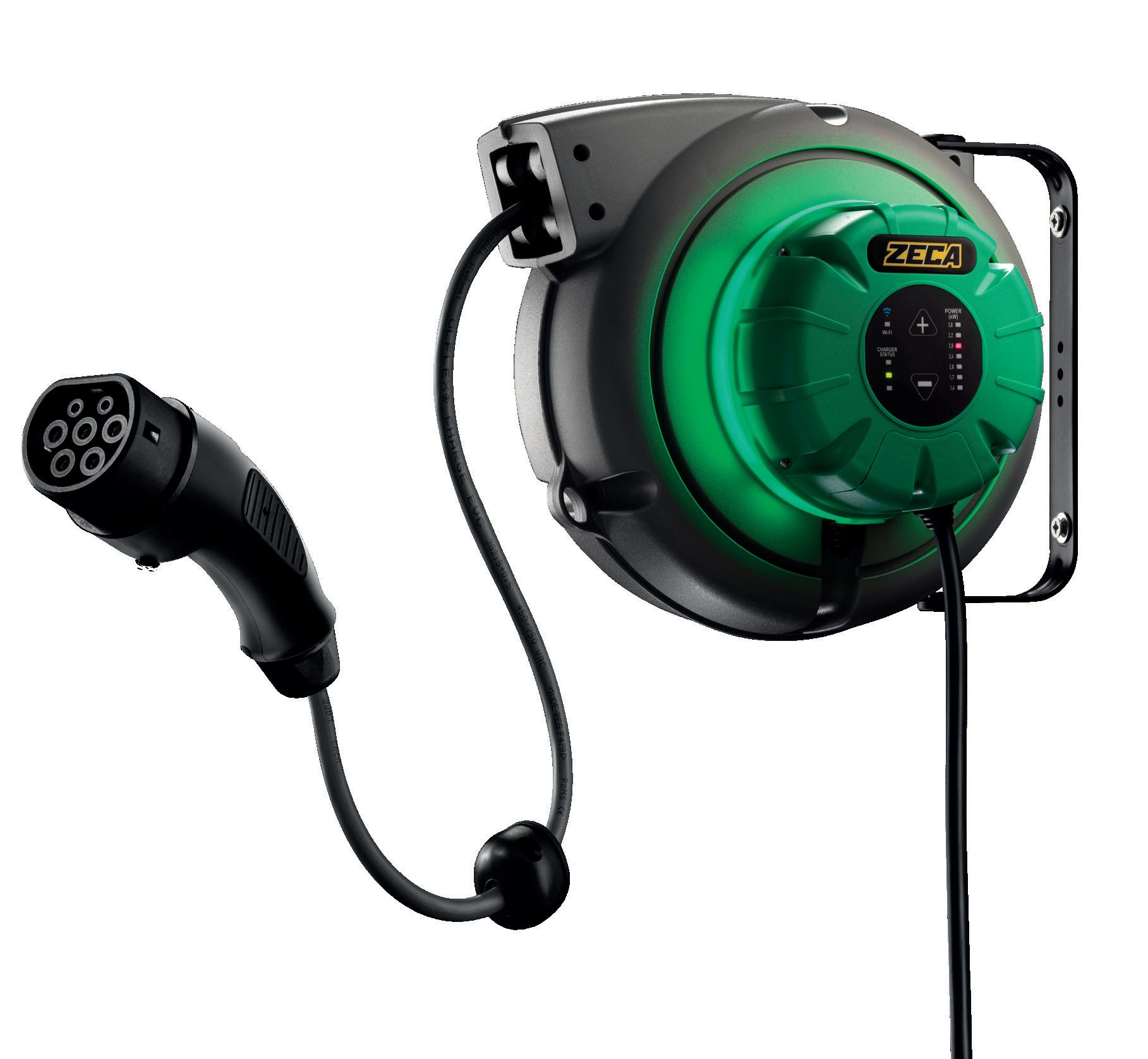
EV REELS
THE ZECA RANGE FOR CHARGING ELECTRIC VEHICLES
Cleanliness
Your hands won’t get dirty because there is no direct contact with the cable.
Safety
Cables are safely stored without the risk of getting caught
Tidiness
No more tangled cables in the way.
Time saving
Charging your car will be much simpler and quicker

If you already have a wallbox
Reel with built-in wallbox
The extension, connected to your wallbox, helps to protect the cables and keep your garage tidy.
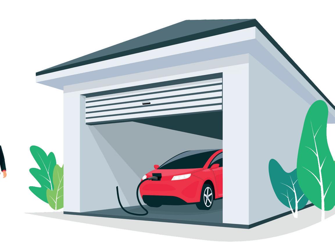
The reel with built-in wallbox combines the functionality of the wallbox with the convenience of the reel. All in a single product.
54
EV REELS YOUR WALLBOX ZECA EV REEL
REEL + WALLBOX
for charging electric vehicles
■ SOCKET GUIDE
TYPE 1
Mainly found on Japanese vehicles, Type 1 sockets allow single-phase charging only (230V) SAE J1772-2009 MAX 32A 230V
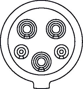
TYP 1
Vor allem bei japanischen Fahrzeugen. Typ1-Steckdosen ermöglichen nur einphasiges Laden (230V) SAE J1772-2009 MAX 32A 230V
TYPE 2
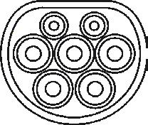
THE MOST WIDELY USED IN EUROPE Type 2 sockets allow single-phase (230V) and three-phase (400V) charging VDE-AR-E-2623-2-2
MAX 32A 230V / 32A 400V
TYP 2
DIE AM WEITESTEN VERBREITETE IN EUROPA Typ-2-Steckdosen ermöglichen einphasiges (230V) und dreiphasiges (400V) Laden VDE-AR-E-2623-2-2
MAX 32A 230V / 32A 400V
55
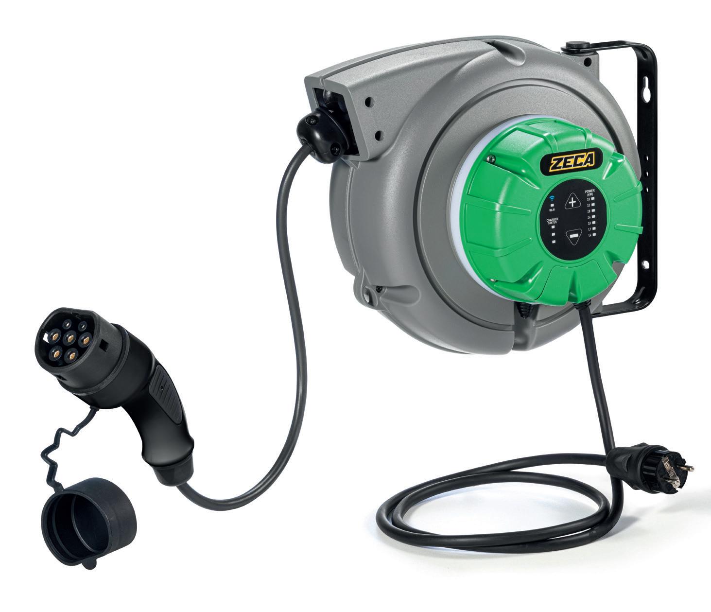
■ EN ■ EN ■ DE ■ DE EV REELS EN 61242 EN 60335-1 2014/35/UE 2006/42/UE 2011/65/UE
mm 345x300x220 Kg 4,5 22 1 ART. Cable Charger Outlet socket Cable Length IP protection rating Wi-fi EV3161WB+ 3G2,5 + 1x0,5 single phase 16A TYPE 1 5 m IP 42 EV3161WB 3G2,5 + 1x0,5 single phase 16A TYPE 1 5 m IP 42 EV3162WB+ 3G2,5 + 1x0,5 single phase 16A TYPE 2 5 m IP 42 EV3162WB 3G2,5 + 1x0,5 single phase 16A TYPE 2 5 m IP 42
EV3WB
dimensioni EV3WB 345mm 13,6in R145mm 5,7in 170mm 6,7in 7mm 0,3in 215mm 8,5in ATTENZIONEINMODIFICA EV2161 WB+WF SAT
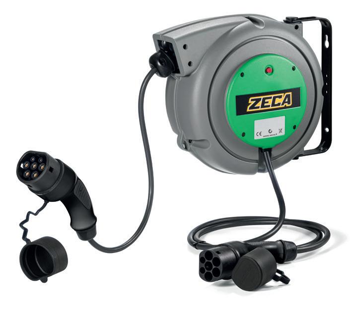
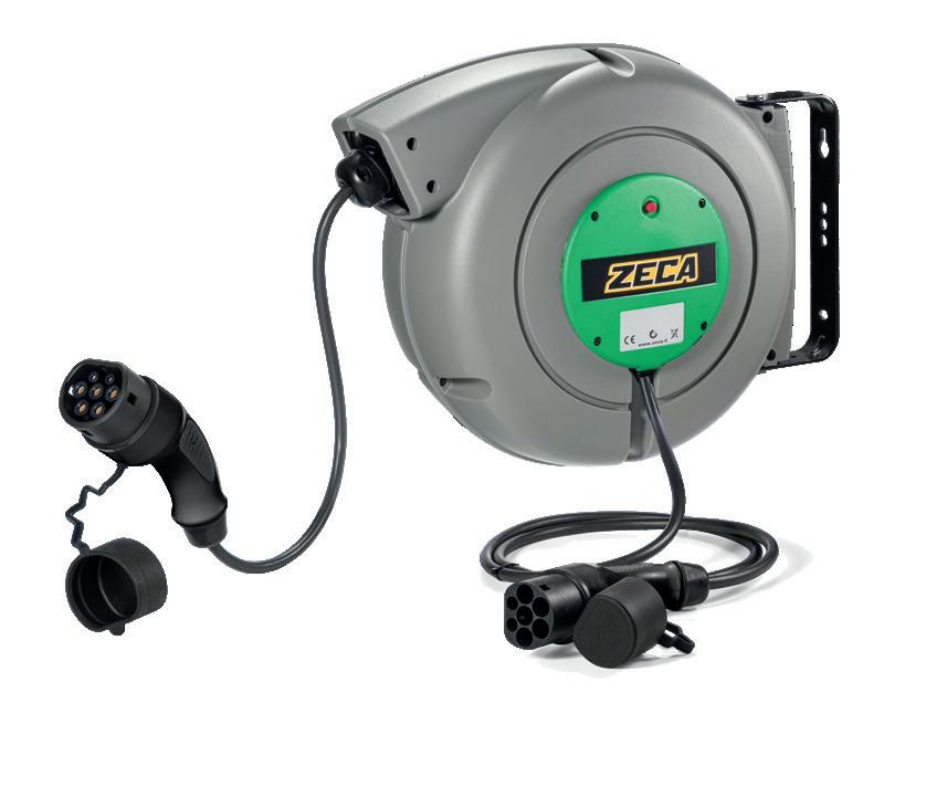
56 dimensioni EV3 7mm 0,3in 170mm 6,7in 350mm 13,8in R145mm 5,7in 160mm 6,3in 804 2023 EV3 - EV4 EN 61242 EN 60335-1 2014/35/UE 2011/65/UE 2006/42/UE mm 41x30,5x18,5 Kg 4,0 24 1 mm 430x400x210 Kg 8,0 1 EN 61242 EN 60335-1 2014/35/UE 2011/65/UE 2006/42/UE 20
ART. Cable Charger Inlet plug Outlet socket Cable length IP protection rating EV2161 3G2,5 + 1x0,5 single phase 16A TYPE 2 TYPE 1 5 m IP42 EV2162 3G2,5 + 1x0,5 single phase 16A TYPE 2 TYPE 2 5 m IP42 ART. Cable Charger Inlet plug socket length rating EV4162T 5G2,5 + 1X0,5 triple phase 16A TYPE 2 TYPE 2 6 m IP42 for
electric vehicles for charging electric vehicles 170mm 6,7in R185mm 7,3in 490mm 19,3in 4mm 0,2in 210mm 8,3in 7000/805 VERSIONE 2023 dimensions EV4 NEW QUICK FIT SEE PAGE 12 AVAILABLE FROM 4TH QUARTER 2023
EV3 EV4 REEL REEL
charging
■ OPTIONAL ACCESSORIES
ALL THESE OPTIONAL ACCESSORIES ARE SUPPLIED DISASSEMBLED
SWIVEL BRACKET ART. 1401
Only suitable for manual use. For wall installation
Nur für den manuellen Gebrauch geeignet. Für die Wandmontage
for charging electric vehicles
FIXED BRACKET ART. 1403
for wall, floor or ceiling installation.


Für die
oder Deckenmontage.
57 EV6 EN 61242 EN 60335-1 2014/35/UE 2011/65/UE 2006/42/UE mm 51x39,5x48,5 Kg 15,0 8 1
Boden-
400 360 195 220 220 251 10,5 55 105 65° 35° 400 360 195 220 220 251 10,5 55 105 65° 35° 400 360 195 220 220 251 10,5 55 105 65° 35° EV6
ART. Cable Charger Inlet plug Outlet socket Cable length IP protection rating EV6321 3G6 + 1x0,5 single phase 32A TYPE 2 TYPE 1 8 m IP44 EV6322 3G6 + 1x0,5 single phase 32A TYPE 2 TYPE 2 8 m IP44 EV6162T 5G2,5 + 1x0,5 three-phase 16A TYPE 2 TYPE2 8 m IP44 EV6322T 5G6 + 1x05 three-phase 32A TYPE 2 TYPE 2 8 m IP44 dimensions EV6
Wand-,
REEL
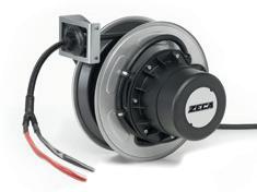
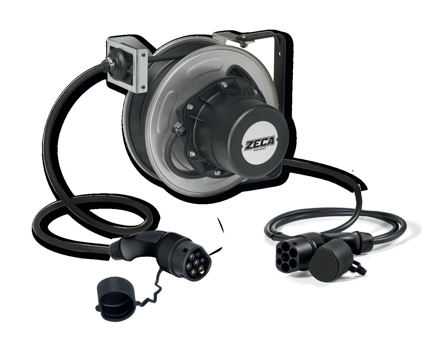
CABLE REEL
FOR BATTERY CHARGER
ART. 1425
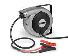
Cable reels designed to facilitate the connection between the battery charger and the battery being charged.
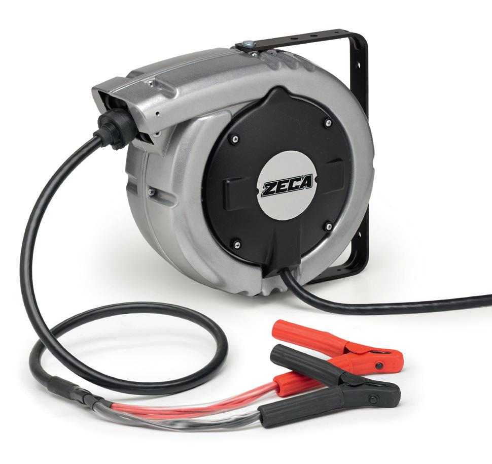
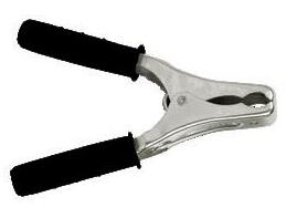
• Max voltage 48V
• All reels are provided with insulated clips, black and red, capacity 200A and length 160mm.
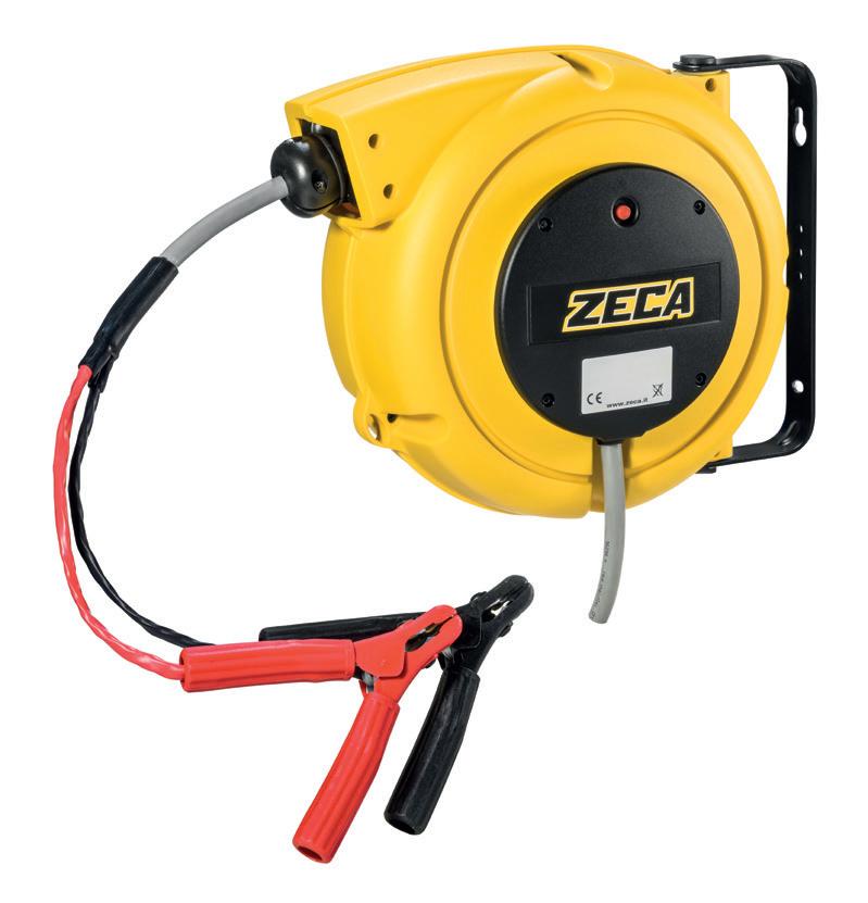
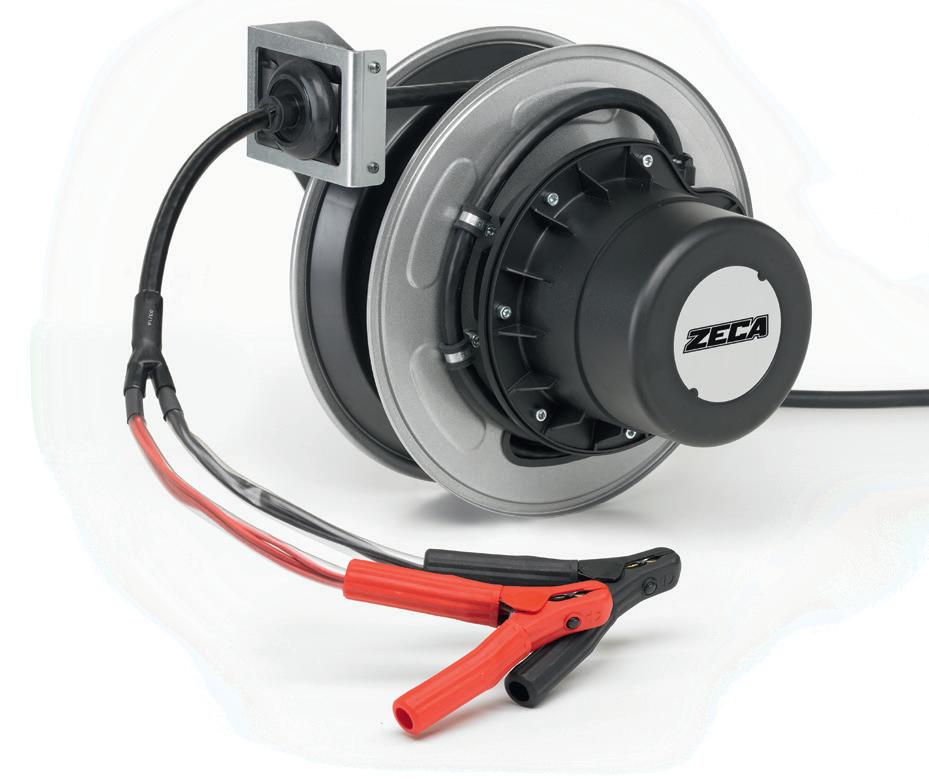
• The models Art.1424 and 1425 are provided with roller cable guide and ratchet Art. 1406
• Max Spannung 48V
• Alle Aufroller sind mit Isolierter Zange, schwarz und rot, geliefert. Kapazität 200A und Länge 160mm.
• Die Modelle Art. 1424 und 1425 sind mit Kabelführung und Arretierung Art. 1406 geliefert
* IP rating referers to reels without clips
58
ART. 6216
ART. 1424
EN 61242 EN 60335-1 2011/65/UE 2006/42/UE TECHNICAL FEATURES TECHNISCHE MERKMALE ■ EN ■ DE no. of conductors cross-section (mm²) cable length (m) ART. A A cable type Ø cable (mm) collector capacity (A) IP rating* incoming cable length (m) 2 X 9 6 4216 20 30 PVC 13 30 IP42 1 9 6216 20 30 PVC 13 30 IP42 2 15 12 1424 30 50 PVC 17,5 50 IP65 2 20 12 1425 50 100 PUR 17,5 100 IP65 2 32 17 1796 80 150 TPE 20,5 150 IP65 2
BATTERY CHARGER ART.
4216
ART. 4216 SP
CABLE REELS
FOR DRIVE BATTERY CHARGING
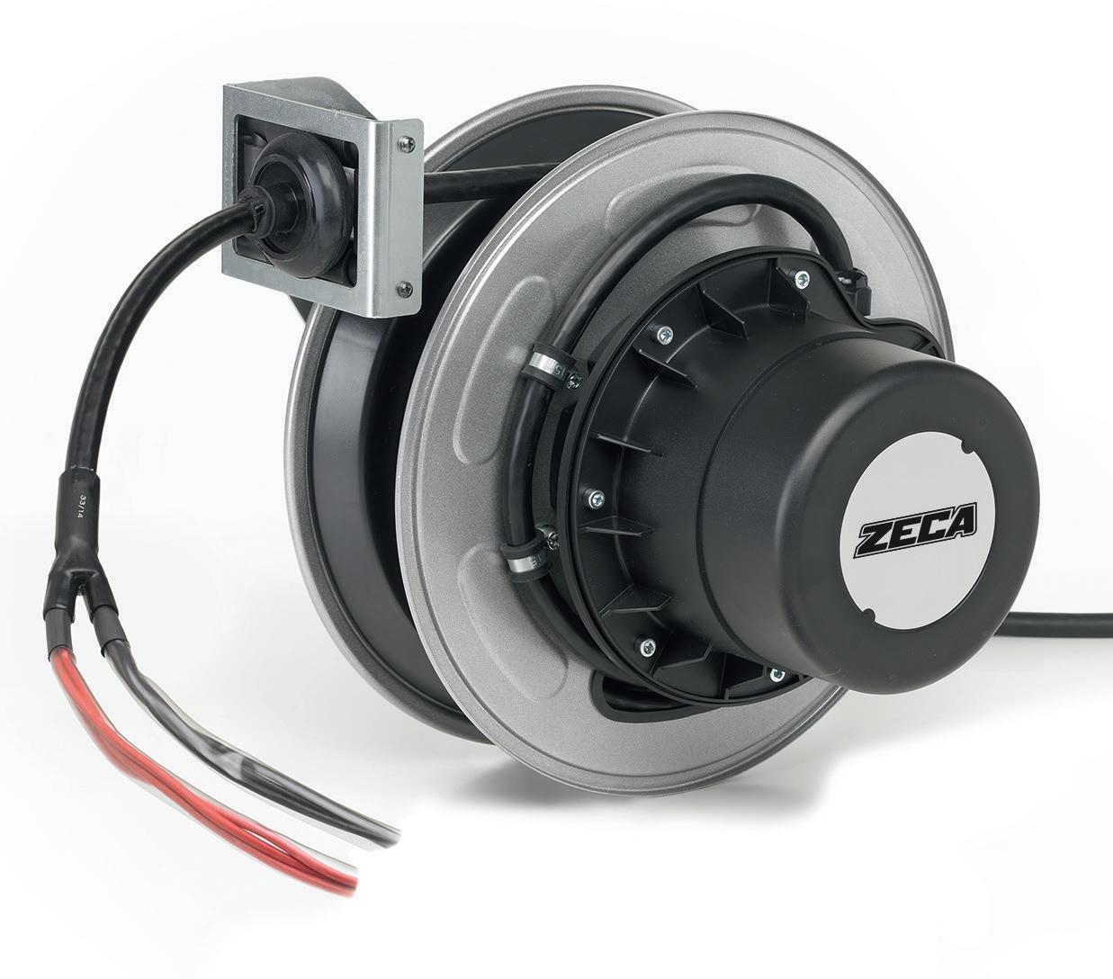
To facilitate the connection between the battery charger and the vehicle.
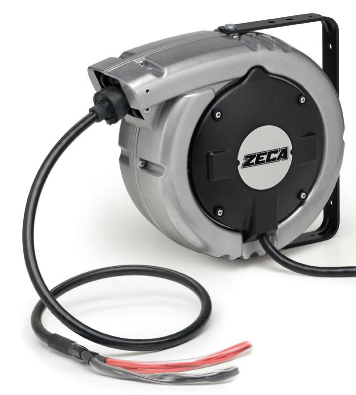

• Voltage Max 48V.
• Supplied without connector.
ART. 6216 SP
ART. 1424 SP
ART. 1425 SP
• Max. Spannung 48 V.
• Wird ohne Stecker geliefert.
59 BATTERY CHARGER
mm 360x310x185 Kg 5,00 Art. 4216 1 mm 400x370x260 Kg 13,00 Art. 6216 1 mm 400x400x400 Kg 15,00
1424
Art.
- 1425 1
■ EN ■ DE TECHNICAL FEATURES no. of conductors cross-section (mm²) cable length (m) ART. A A cable type Ø cable (mm) collector capacity (A) IP rating* incoming cable length (m) 2 X 9 6 4216 SP 20 30 PVC 13 30 IP42 1 9 6216 SP 20 30 PVC 13 30 IP42 2 15 12 1424 SP 30 50 PVC 17,5 50 IP65 2 20 12 1425 SP 50 100 PUR 17,5 100 IP65 2 32 17 1796 SP 80 150 TPE 20,5 150 IP65 2 EN 61242 EN 60335-1 2011/65/UE 2006/42/UE
BARRIERS REEL
Delimiter cable reel, temporary barriers to cordon off a specific area or signal hazardous areas. Available in 3 lengths:
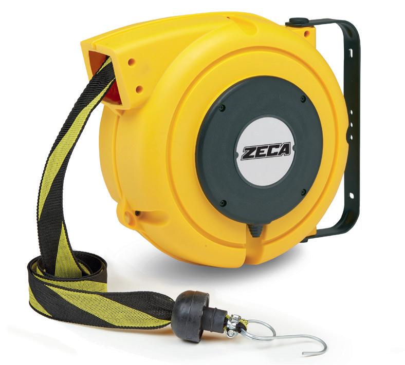
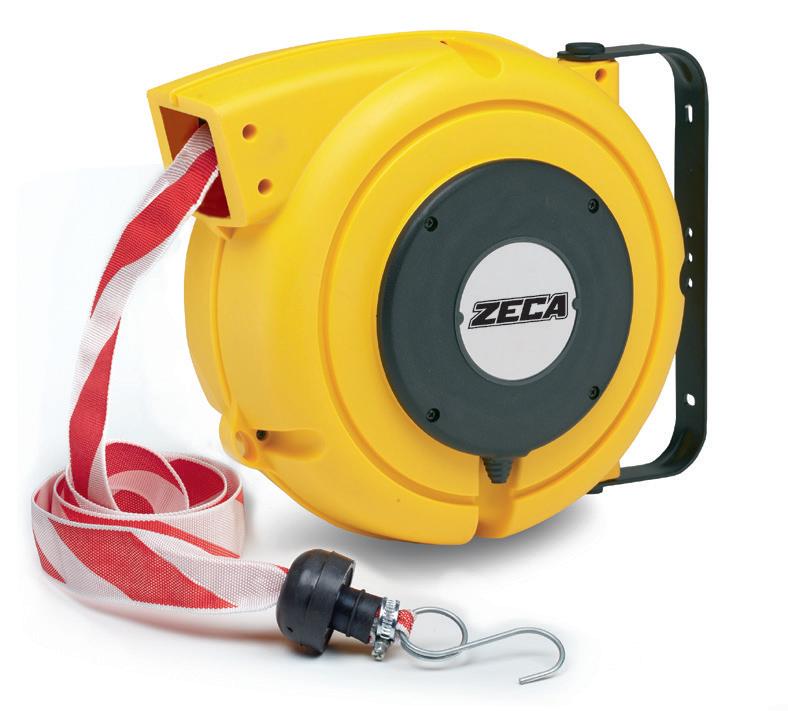

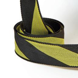
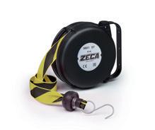
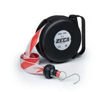
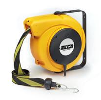
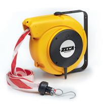
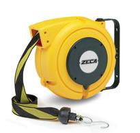
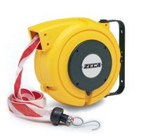
• 8 metres art. 9801
• 16 metres art. 5801
• 20 metres art. 4801
• All the tapes are made of polypropylene
• It comes complete with a metal hook for fastening.

Wickler für Abgrenzungen, temporäre Barrieren und zur Abgrenzung eines begrenzten Bereichs oder zur Signalisierung von Gefahrenzonen, erhältlich in 3 Längen.
• 8 Meter Art. 9801
• 16 Meter Art. 5801
• 20 Meter Art. 4801
• Alle Bänder sind aus Polypropylen hergestellt
• Wird komplett mit Metallhaken zur Befestigung geliefert.
60 SAFETY BARRIERS REEL
SAFETY
ART. 4801 RW 4801 BY 5801 RW 5801 BY 9801 RW 9801 BY Description Automatic cable reel with metal hook Tape length m. 20 m. 16 m. 8 Tape colour 44 60 100 1 mm 360x310x185 Kg 4,0 mm 410x305x185 Kg 4,0 mm 240x195x120 Kg 2,0 YELLOW
BLACK BY models LENGTH TAPE FROM 8 TO 20 M. RED - WHITE RW models HANDY FASTENING HOOK 4801 RW - 4801 BY 7mm 0,3in 170mm 6,7in 350mm 13,8in R145mm 5,7in 160mm 6,3in 804 2023 dimensions 200mm 7,9in 305mm 12in 8mm 0,3in 30° 45° 280mm 11in 145mm 5,7in 200mm 7,9in 305mm 12in 8mm 0,3in 280mm 11in 145mm 5,7in 5801 RW - 5801 BY dimensions 9801 RW - 9801 BY 7mm 0,3in R95mm 3,7in 100mm 3,9in 215mm 8,5in 105mm 4,1in dimensions ISO EN 1200 2006/42/EC ■ EN GENERAL FEATURES ■ DE ALLGEMEINE MERKMALE
-

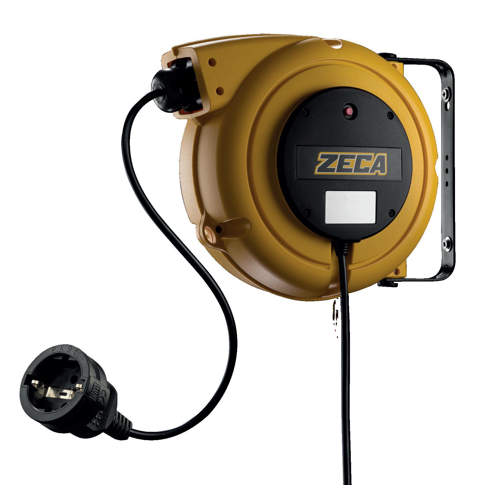
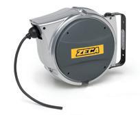
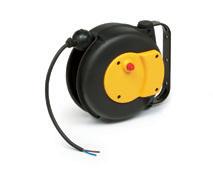
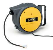
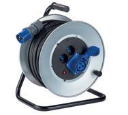
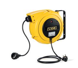
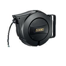
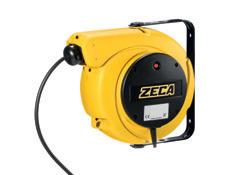
61 4000 series page. 62 AL 41 BLACK series page. 63 AL41 series page. 64 5000 series page 64 9000 series page. 65 AM40 series page. 65 3500 series page. 66
7mm 0,3in 170mm 6,7in 350mm 13,8in 160mm 6,3in 804 2023
Extension reels
4000 SERIES
15 M EXTENSION
■ 4315/S ART. GREY 4315/SGS ART. GREY 4325/15/A GS3 ART. BLUE 4315 4325/15 4315/GS 4315/GS 3 Description Extension reel Extension reel Extension reel with Schuko socket and plug Extension reel with 3 Schuko sockets and plug Cable lenght 15 m 15 m 15 m 15 m Cable type 3G1,5-PVC 3G2,5-PVC 3G1,5-PVC 3G1,5-PVC Socket, plug, incoming cable NO NO YES Schuko plug and socket YES Schuko triple plug and socket W (20°C) 1200 1900 1200 1200 W (20°C) 1800 2500 1800 1800 Thermic protection YES YES YES YES V max 500 500 500 500 44 44 44 44 1 mm 360x310x185 Kg 5 mm 360x310x185 Kg 5 mm 360x310x185 Kg 5 mm 360x310x185 Kg 5
• Swivelling bracket.
• Cable ratchet stop device.
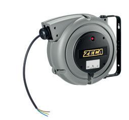
• With incorporated thermic protection
• Double earth contact.
• Working temperature: -5°/+50°C.
The complete range of reels, which can be supplied with different types of cables, is in the industrial reel section on page 10 onwards.
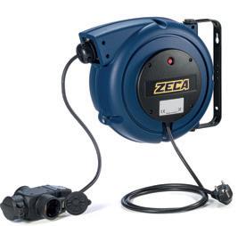

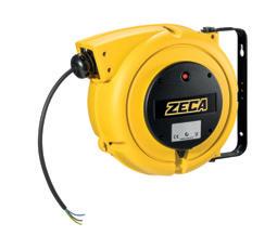
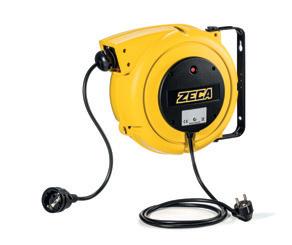
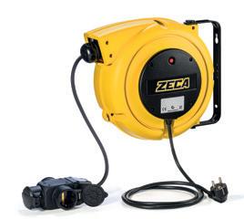
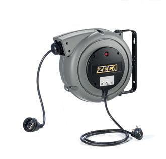
Das komplette Angebot an Kabeltrommeln mit unterschiedlichen Kabeltypen finden Sie im
■ 350mm 13,8in R145mm 5,7in
• Schwenkbare Halterung zur Befestigung.
• Zahnstangen-Kabelstopper, alle 50 cm einrastbar.
• Eingebauter Wärmeschutz.
• Doppelter Erdungskontakt.
EN Kabeltrommeln mit Federrückzug, geeignet zur Verwendung als Verlängerungskabel, zur ständigen Verfügbarkeit einer Steckdose. 230V 230V 7mm 0,3in 170mm 6,7in
• Umgebungstemperatur bei der Verwendung: -5/+50 °C.
804 2023 dimensions
DE 160mm 6,3in
EN 61242 EN 60335-1 2014/35/UE 2006/42/UE 2011/65/UE
62 4000 SERIES
Reel with spring retraction mechanism, suitable for use as extensions, allows the user to have a power supply available at all times. TECHNICAL FEATURES TECHNISCHE MERKMALE
Abschnitt Industrielle Kabeltrommeln ab Seite
10.
AL 41
TECHNICAL FEATURES
• Die-cast aluminium frame painted with black epoxy powders.
• Roller guide.
• Cable ratchet stop device.
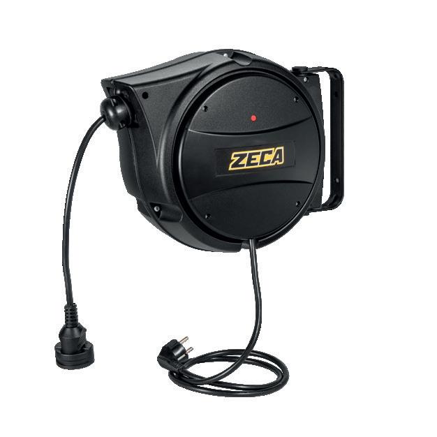
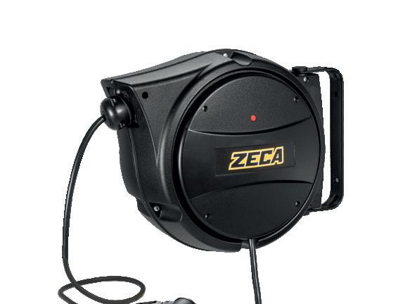
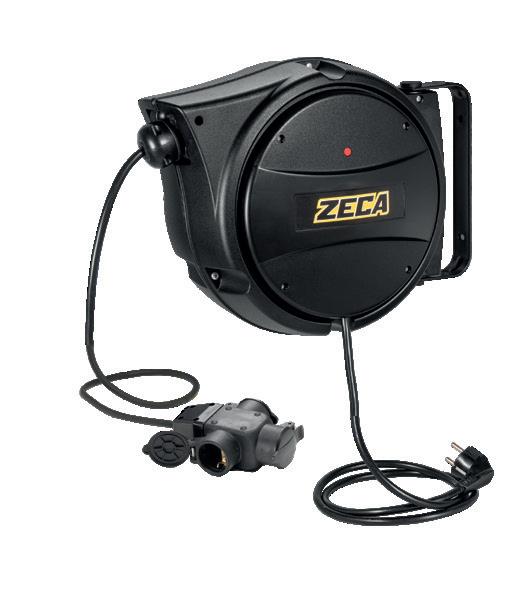
• Double earth contact.
• Collector insulation voltage 2.5 KV.
• Sliding contacts with collector ring and brushes.
• Protection rating IP42.
• Working temperature -5°C/+50°C.
• Gehäuse aus druckgegossenem Aluminium, Beschichtung mit schwarzem Epoxidpulver.
• Kabelführungsöffnung mit Rollen.
• Stoppvorrichtung
• Doppelter Erdungskontakt.
• Isolationsspannung des Kollektors 2,5 kV.
• Schleifkontakte mit Schleifring und Bürsten.

• Schutzart IP42.
• Umgebungstemperatur bei der Verwendung -5 °C/+50 °C.
63 AL BLACK SERIES
dimensions AL41 6mm 0,2in 130mm 5,1in R145mm 5,7in 375mm 14,8in 165mm 6,5in SERIES AL41 / AL47 / AL48 / AL81
BLACK SERIES 15 M EXTENSION ALUMINIUM BODY ALUMINIUM BODY
ART. AL41/315/B
AL41/315/B GS
Description Extension
Cable lenght 15 m 15 m 15 m Cable type 3G1,5-PVC 3G1,5-PVC 3G1,5-PVC Socket, plug, incoming cable NO YES Schuko plug and socket YES Schuko triple plug and socket W (20°C) 1200 1200 1200 W (20°C) 1800 1800 1800 Thermic protection YES YES YES V max 500 500 500 44 1 mm 360x310x185 - Kg 6,0 230V 230V
AL41/315/B GS3
reel Extension reel with Schuko socket and plug Extension reel with 3 Schuko sockets and plug
■ EN
TECHNISCHE MERKMALE ■ DE EN 61242 EN 60335-1 2014/35/UE 2006/42/UE 2011/65/UE
AL41 SERIES 5000 SERIES
15 M EXTENSION
Reel with spring retraction mechanism, suitable for use as extensions, allows the user to have a power supply available at all times.
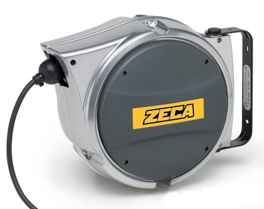
11.5 M EXTENSION
Kabeltrommeln mit Federrückzug, geeignet zur Verwendung als Verlängerungskabel, zur ständigen Verfügbarkeit einer Steckdose.
5000 SERIES
TECHNICAL FEATURES ■
• Diecast aluminium casing, undercoat paint finish.
• Swivelling bracket.
• Cable ratchet stop device.
• Double earth contact.
• Working temperature: -5°/+50°C.
TECHNISCHE
• Außengehäuse aus Aluminiumdruckguss, einbrennlackiert.
• Schwenkbarer Bügel.
• Stoppvorrichtung.
• Doppelerdungskontakte.
• Umgebungstemperatur -5°/+50°C.
TECHNICAL FEATURES
• Swivelling bracket.
• Cable ratchet stop device.
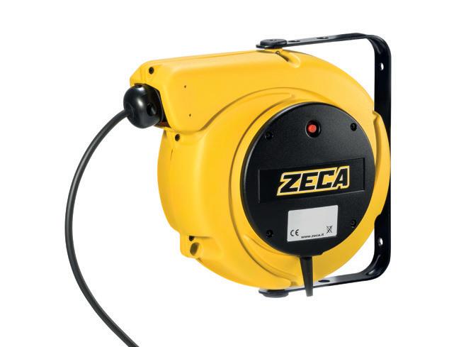
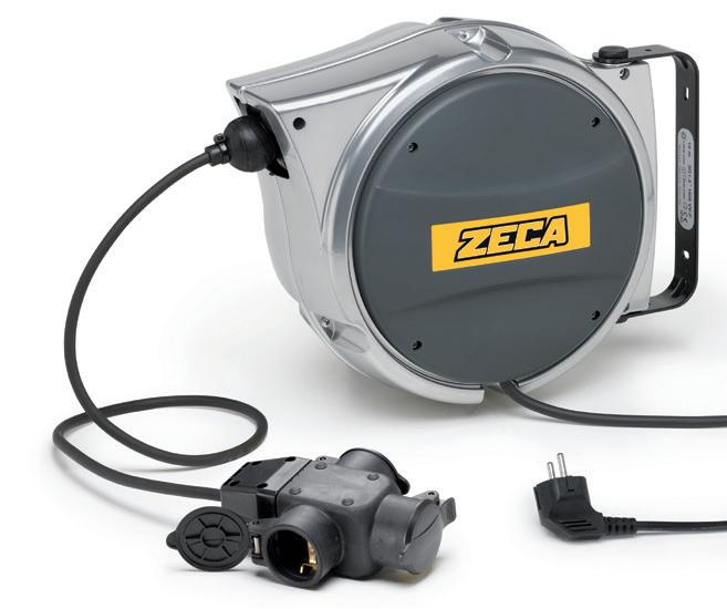
• With incorporated thermic protection
• Double earth contact.
• Working temperature: -5°/+50°C.
TECHNISCHE
• Schwenkbarer Bügel.
• Stoppvorrichtung.
• Mit Überhitzungsschutz
• Doppelerdungskontakte.
• Umgebungstemperatur -5°/+50°C.
64 AL 41 SERIES 5000 SERIES ART. AL41/315 GS3 AL41/315 5827/XF Description
Schuko sockets and plug Extension
Extension reel Cable lenght 15 m 15 m 11,5 m Cable type 3G1,5-PVC 3G1,5-PVC 3G1,5-PVC Socket, plug, incoming cable YES Schuko triple plug and socket NO NO W (20°C) 1200 1200 1200 W (20°C) 1800 1800 1800 Thermic protection YES NO YES V max 500 500 500 44 44 57 1 mm 360x310x185 Kg 5 mm 360x310x185 Kg 5 mm 310x310x170 Kg 3,5
Extension reel with 3
reel
200 R145 6 130 175 165 dimensions AL41 AL41/315 GS3 AL41/315
MERKMALE dimensions 5000 200mm 7,9in 305mm 12in 8mm 0,3in 30° 45° 280mm 11in 145mm 5,7in ■ EN
DE ALUMINIUM BODY ALUMINIUM BODY
EN ■ DE
■
■
EN
MERKMALE
DE
■
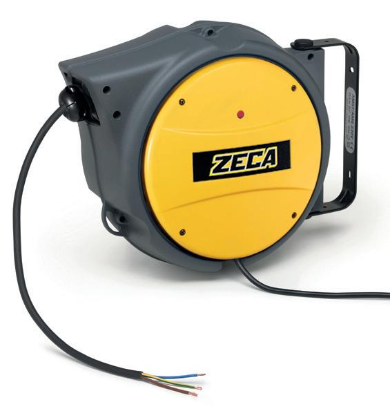
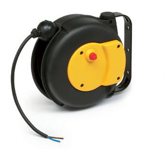
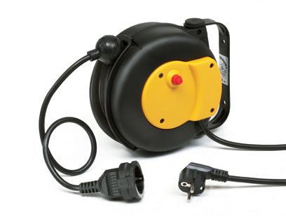
65 9000 SERIES AM SERIES ART. 9004/GS 9004 Description Extension reel with Schuko socket and plug Extension reel Cable lenght m 6 m 6 Cable type 3G1,5-PVC 3G1,5-PVC Socket, plug, incoming cable YES Schuko plug and socket NO W (20°C) 1400 1400 W (20°C) 1900 1900 Thermic protection YES YES V max 500 500 100 100 1 mm 240x195x120 Kg 2,5 mm 240x195x120 Kg 2,5
6 M EXTENSION
M EXTENSION AM SERIES 7mm 0,3in R95mm 3,7in 100mm 3,9in 215mm 8,5in 105mm 4,1in dimensions dimensions ART. AM40/315 Description Extension reel Cable lenght m 15 Cable type 3G1,5-PVC Socket, plug, incoming cable NO W (20°C) 1200 W (20°C) 1800 Thermic protection YES V max 500 44 1 mm 360x310x185 Kg 2,5 6mm 0,2in 130mm 5,1in R145mm 5,7in 375mm 14,8in 165mm 6,5in SERIES AL41 / AL47 / AL48 / AL81
9000 SERIES
15
3500 SERIES
HAND OPERATED CABLE COILERS
■ EN MANUAL CABLE REELS All the models are “CE” marked except incomplete models (without sockets and/or without cable), where “CE” marks must be placed by whom fits sockets and/or cables and puts on the market.
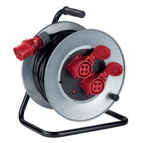
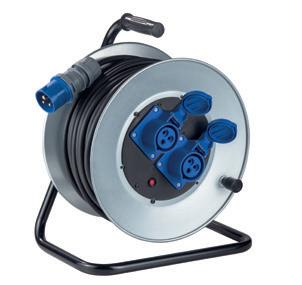
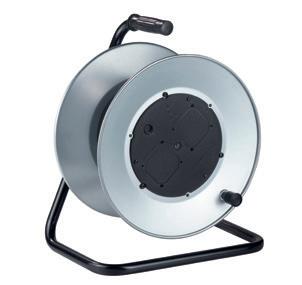
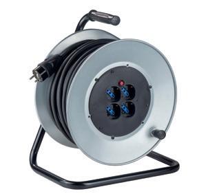
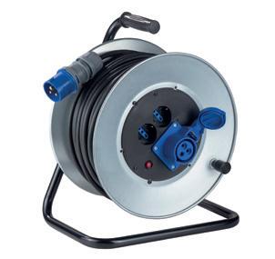
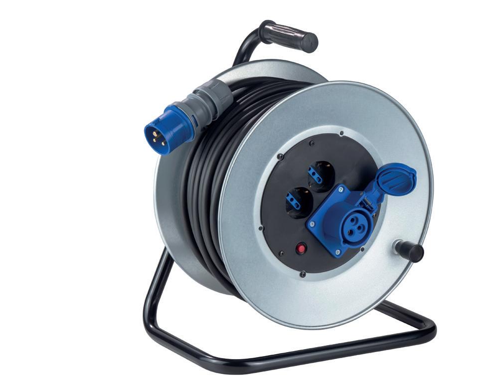
■ DE MANUELLE KABELTROMMELN
Alle Modelle sind CE gekennzeichnet, mit Ausnahme der nicht komplettierten Modelle (ohne Anschlüsse und/ oder ohne Kabel). Für diese Modelle muss der Käufer für die CE Zeichen sorgen.
REEL LOCK BRAKE
INTERNAL BODY IN PLASTIC FOR MAXIMUM SAFETY
GALVANISED FLANGE
STEEL PIPE STAND, OVEN COATED.
dimensions
66
Socket type No cable Metres of cable ART. Typecableof W Circuit breaker no sockets sans prises – NO cable 3501 – – NO 4 sockets 10/16 A 2P+T Schuko (schuko/france plug) –3G1.5 3G1.5 3G2.5 3G2.5 NO cable 25 40 25 40 3507 3508 3509 3510 3511 –PVC PVC PVC PVC –1400 1200 2100 1800 YES YES YES YES YES 2 sockets 10/16 A 2P+T Schuko 1 socket (blue) CEE 16A (plug CEE 16A 2P+T) –3G1.5 3G1.5 3G2.5 3G2.5 NO cable 25 40 25 40 3512 3513 3514 3515 3516 –PVC PVC PVC PVC –1400 1200 2100 1800 YES YES YES YES YES 2 socket (blue) CEE 16A (plug CEE 16A 2P+T) –3G1.5 3G1.5 3G2.5 3G2.5 3G2.5 NO cable 25 40 25 40 30 3517 3518 3519 3520 3521 3526 –PVC PVC PVC PVC RUBBER –1400 1200 2100 1800 1800 YES YES YES YES YES YES 2 socket (red) CEE 16A 16 A 3P+T 380V (plug CEE 16A 3P+T) –4G1.5 4G1.5 4G2.5 4G2.5 NO cable 25 40 30 30 3522 3523 3524 3525 3527 –PVC PVC PVC RUBBER –2200 1900 2500 2500 NO YES YES YES YES EN 61242 EN 60335-1 2014/35/UE 2011/65/UE 3500 SERIES

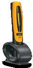
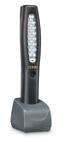
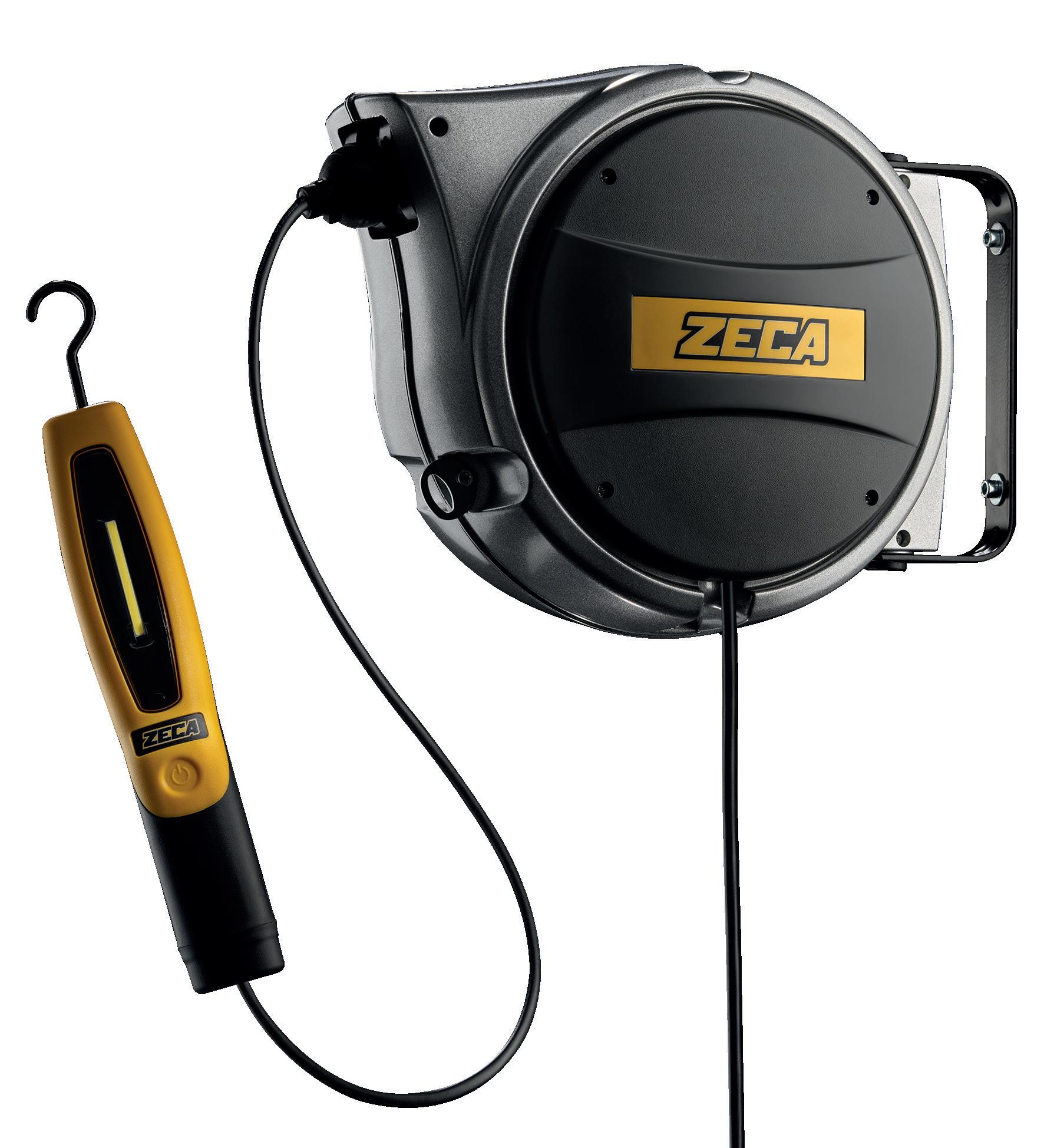
67 345 page 68 342 page 69 Lamps 110 150 105 320
COB LED
RECHARGEABLE LAMP 345
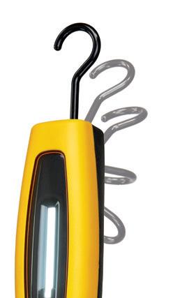
TECHNICAL FEATURES
• COB LED light source.
• Electronic control of the charge; the lamp can be kept always on the battery charger.
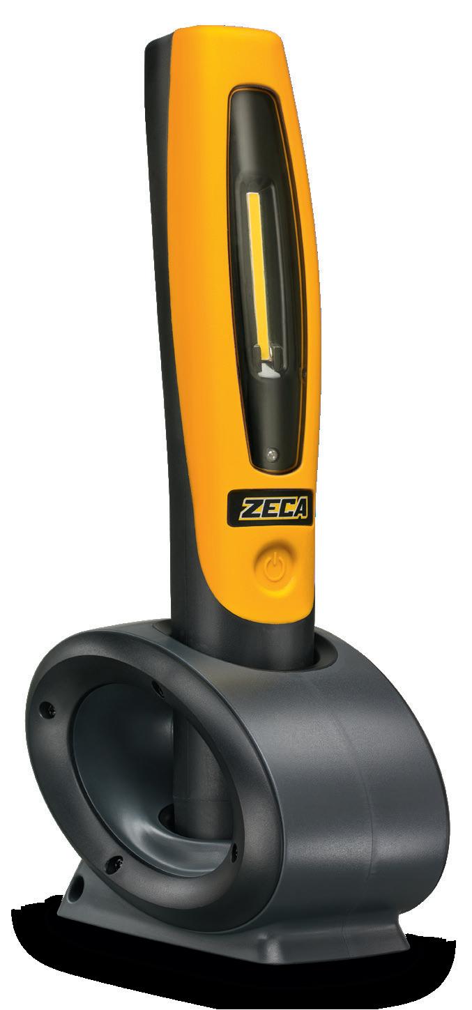
• Fixed red pilot light on the lamp: flat battery. Flashing red light: lamp in recharge.
Fixed green light: charge completed, charge maintenance function.
TECHNISCHE MERKMALE
• COB-LED-Lichtquelle.
• Elektronische Ladekontrolle; die Lampe kann immer am Ladegerät bleiben.
• Kontrollleuchte mit rotem Dauerlicht: Lampe entladen.
Rotes Blinklicht: Lampe wird geladen.
Grünes Dauerlicht: Ladevorgang abgeschlossen, Ladungspflegefunktion.
ART. 345
Rechargeable lamp + battery charger
Wiederaufladbare Lampe + Batterieladegerät
ART. 345/12
320
■ dimensions 345 110 150 105
ART. 345/VY - Transparent cover
ART. 345/L - Portable lamp only
ART. 345/C - Battery charger only
ART. 345/VY - Transparente Abdeckung
ART. 345/L - Nur tragbare Lampe
CAUTION: when the battery is almost flat, a red LED will light up on the lamp. When the switch no longer stays on, it means that the battery is flat and the lamp needs to be recharged.
ACHTUNG: Wenn der Akku schwach ist, leuchtet eine rote LED an der Lampe auf. Wenn sich der Schalter nicht mehr einschalten lässt, bedeutet dies, dass der Akku vollständig entladen ist und die Lampe wieder aufgeladen werden muss.
Complete displayer with 12 lamps art. 345 Leuchtkopf komplett mit 12 Lampen Art. 345
340x160x90 mm - 0,900 Kg
EN 60598-1 EN 60598-2-8 EN 60335-1 2014/35/UE 2011/30/UE 2011/65/UE
68 345 UPDATED VERSION 50%MORELIGHT
■ EN ■ DE ART. 345 Description COB LED rechargeable lamp Light source COB LED Power 4,5 W Lux / Lumen 900 LUX @ 50 CM - 500 LUMEN Angle 120° Battery life 2,5h standard mode 4h energy saving Charging time 3,5h Battery 3,7 V LiPo - 4400 mAh Battery charger 100/240 V (50/60 Hz) Output 5V 2A 150 1
ART. 345/C - Nur Akkuladegerät SPARE PARTS
ART. 342
Rechargeable lamp + battery charger
Wiederaufladbare Lampe + Batterieladegerät
ART. 342/9
Complete displayer with 9 lamps art. 342 Leuchtkopf komplett mit 9 Lampen Art. 342
LED
RECHARGEABLE LAMP 342
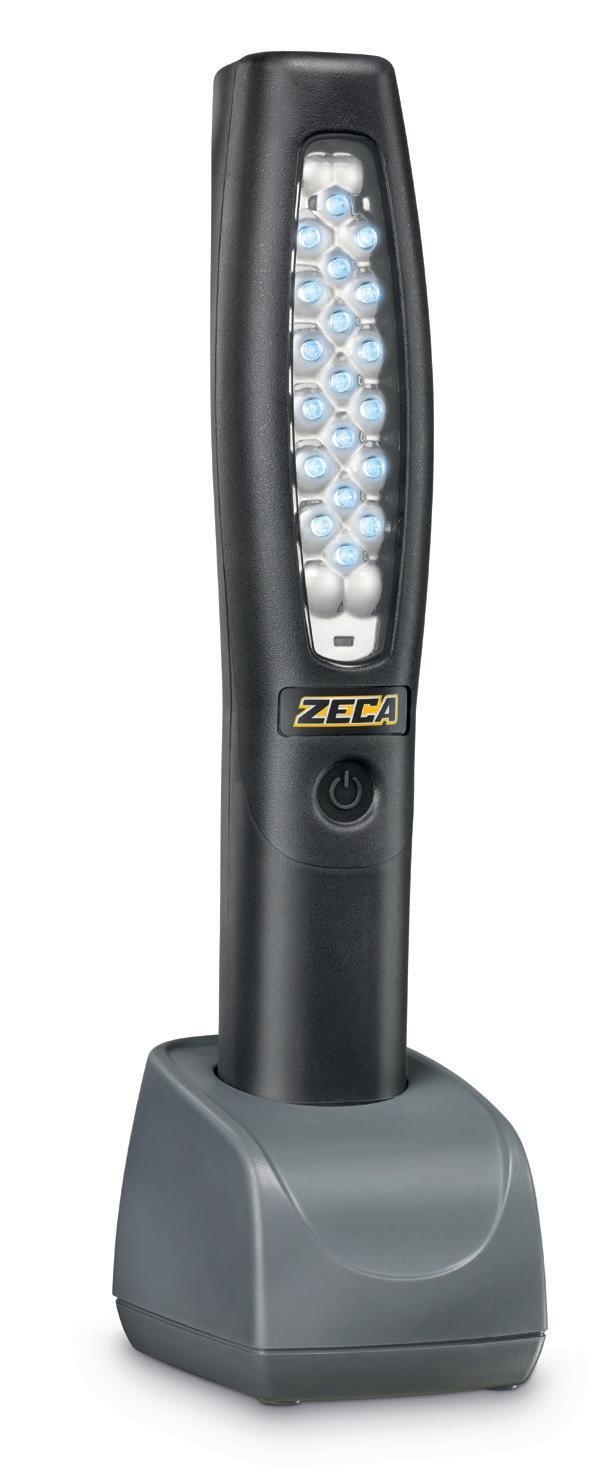
■ EN
TECHNICAL FEATURES
• 19 LED light source.
• Electronic control of the charge; the lamp can be kept always on the battery charger.
• Fixed red pilot light on the lamp: flat battery. Flashing red light: lamp in recharge.
Fixed green light: charge completed, charge maintenance function.
■ DE
TECHNISCHE MERKMALE
• Lichtquelle 19 LEDs.
• Elektronische Ladekontrolle; die Lampe kann immer am Ladegerät bleiben.
• Kontrollleuchte mit rotem Dauerlicht: Lampe entladen.
Rotes Blinklicht: Lampe wird geladen.
Grünes Dauerlicht: Ladevorgang abgeschlossen, Ladungspflegefunktion.
■ SPARE PARTS
ART. 342/VB - Transparent cover
ART. 342/L - Lamp only
ART. 342/C Charging base
ART. 342/VB - Transparente Abdeckung
ART. 342/L - Nur Lampe
ART. 342/C Ladestation
CAUTION: when the battery is almost flat, a red LED will light up on the lamp. When the switch no longer stays on, it means that the battery is flat and the lamp needs to be recharged.
ACHTUNG: Wenn der Akku schwach ist, leuchtet eine rote LED an der Lampe auf. Wenn sich der Schalter nicht mehr einschalten lässt, bedeutet dies, dass der Akku vollständig entladen ist und die Lampe wieder aufgeladen werden muss.
69 342
dimensions 342
ART. 342 Description LED rechargeable lamp Light source SMD LED Power 1,5 W Lux / Lumen 1500 LUX @ 50 CM - 160 LUMEN Angle 15° Battery life 4.5h standard mode 9h energy saving Charging time 2,5h Battery 3,7 V - 2200 mAh - Li-PO Battery charger 100/240 V (50/60 Hz) 130 1 360x120x95 mm - 1,1 Kg
Reel with lamps
Over 50 models with safety lock Cylinder head spring up to 20.000 cycles
15.5 mt of cable.
Über 50 Modelle mit automatischer Bremsvorrichtung der Kabelaufwicklung Feder für bis zu 20.000 Zyklen getestet 15 m langes Kabel.
REEL FEATURES
Spring-operated cable reel for wall mounting, equipped with inspection lamp
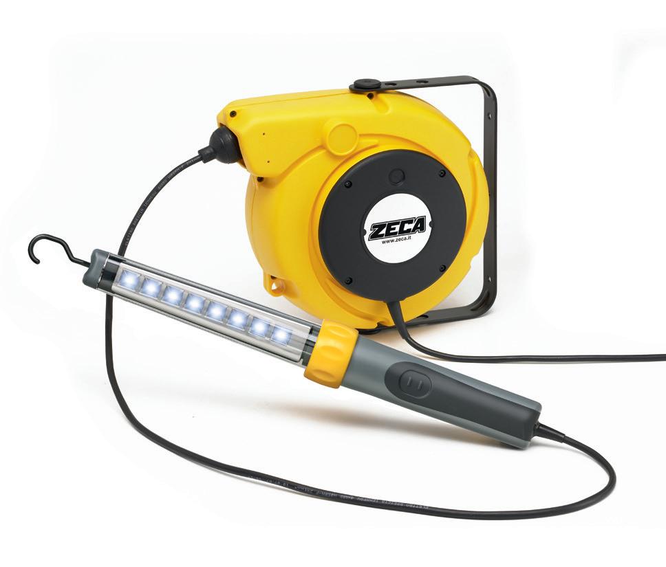
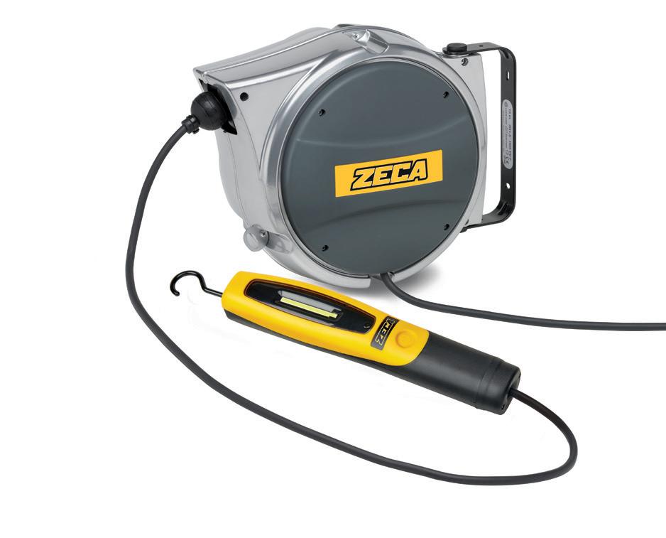
• Structural elements of cable reel in shock-resistant plastic material.
• Diecast aluminium casing, undercoat paint finish.
• Roller cable guide.
• Ratchet stop.
• Wall-mountable steel bracket.
• Rewinding cable spring at high resistance.
• Wiping contacts with collector ring and brushes.
• Working temperature: -5°C/+ 50°C.
•
TECHNISCHE MERKMATE
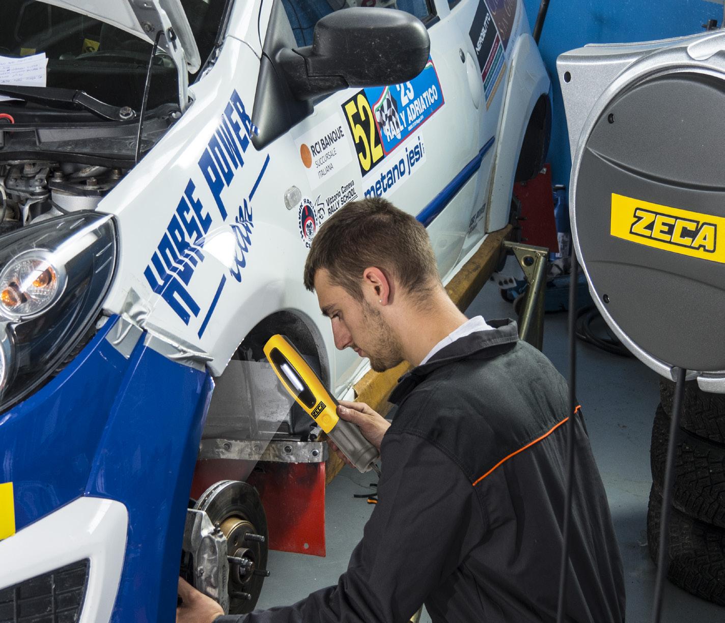
Kabelaufroller mit federantrieb, Für wand befestigung mit handlampe
• Strukturelemente aus stoßfestem Kunststoff.
• Komplett mit Schwenkbarer Bügel für die Befestigung.
• Kabelführung.
• Arretierung.
• Bügel aus Stahlblech zur Befestigung an der Wand.
• Feder aus hochfesten Stahl.
• Gleitkontakte mit Schleifring und Bürsten.
• Umgebungstemperatur: –5°C/+50°C
70
KABELTROMMEL MIT LAMPEN

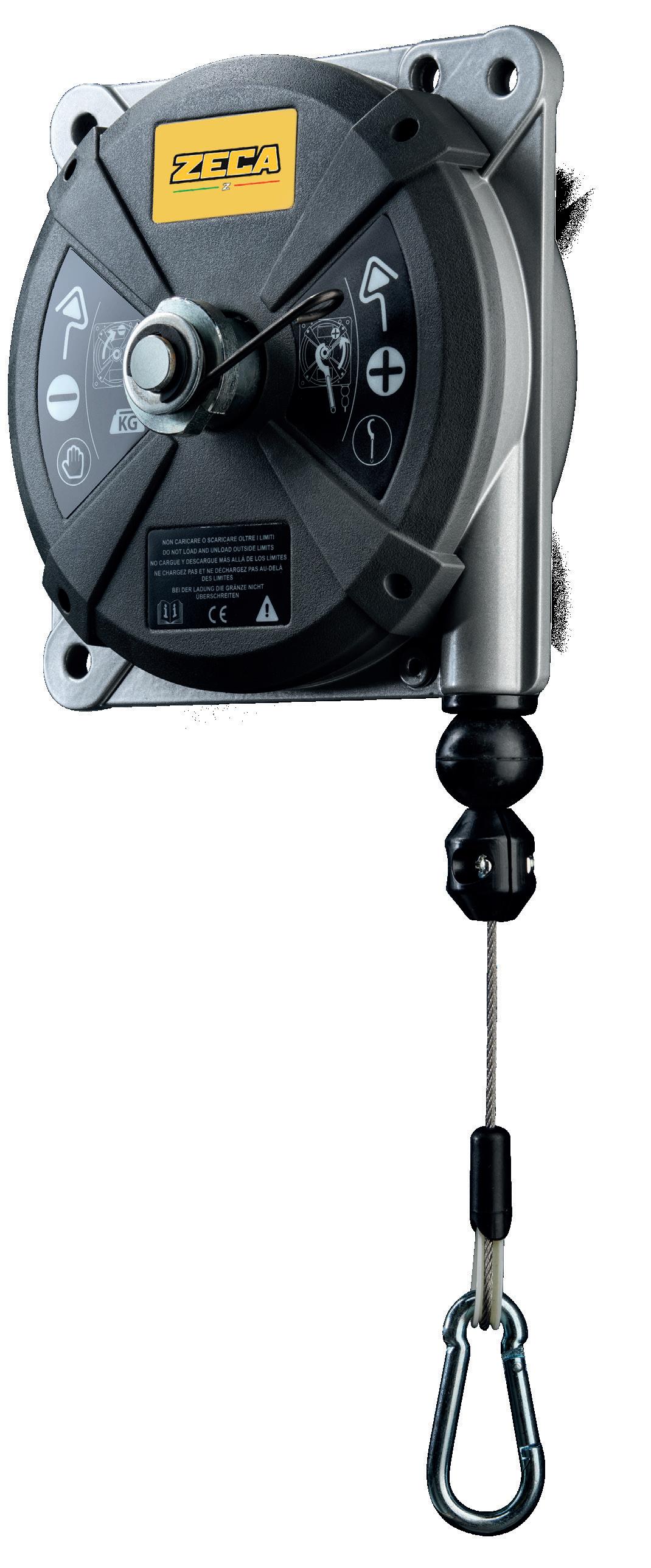
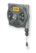
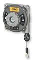
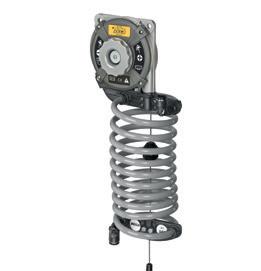
71 Balancers 62X series page 72 63X series page 72 63X AIR series page 74
BALANCERS
WITH ZECA,WORK IS EASIER.
TECHNICAL FEATURES ■ EN
Balancers to support the weight of manual tools, torque wrenches, etc. An essential aid for repetitive jobs, assembly, mass production, packaging, etc. The balancers are made of top-quality materials and withstand particularly heavy-duty work cycles. There are two different sizes.
• Die-cast aluminium case.
• Continuous load adjustment from maximum to minimum value.
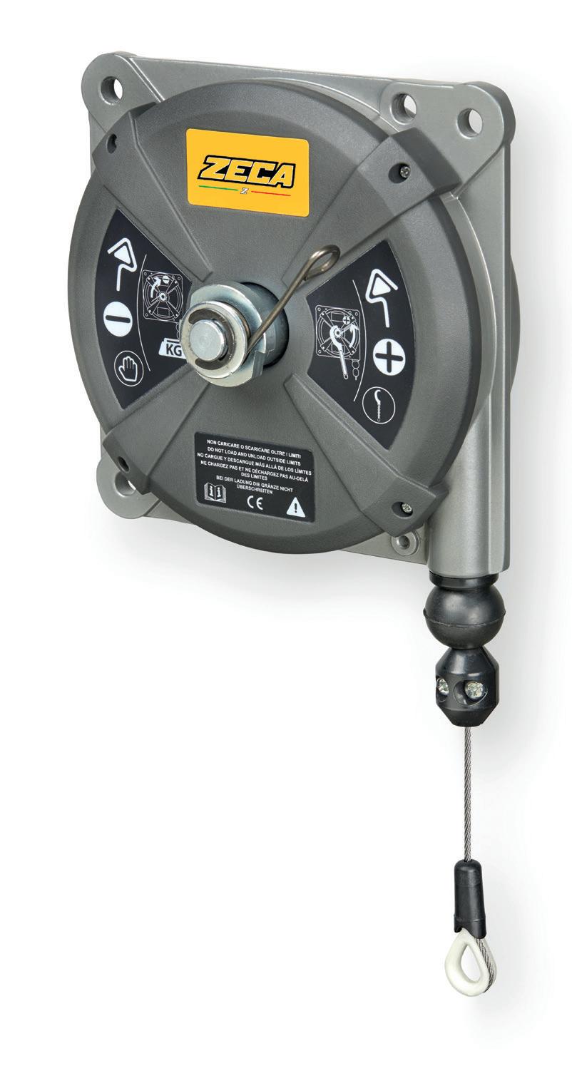
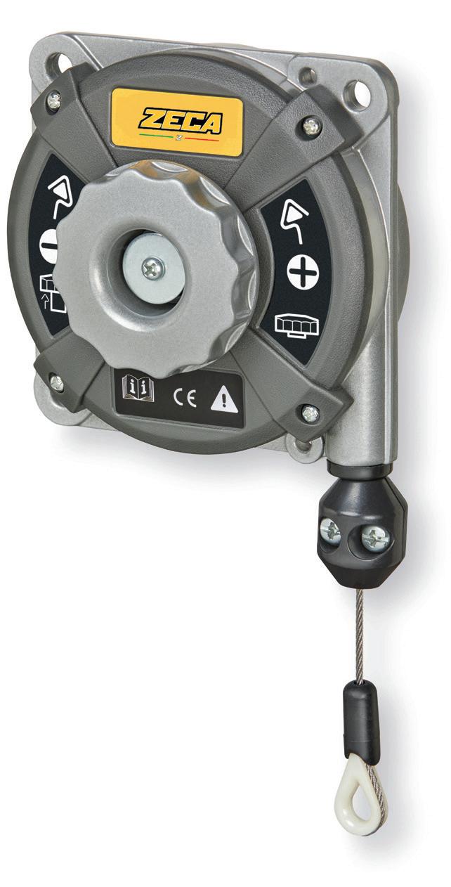
• Easily adjustable cable length to suit every need.
• Four suspension points.
• Three fastening points.
The support cable can be made of stainless steel or HT polyethylene textile fibre.
Balancers um das Gewicht von Handwerkzeugen, Schraubenziehern usw. zu tragen. Ein unentbehrliches Werkzeug für repetitive Arbeiten, Montage, Massenproduktion, Verpackung, usw.
Die Balancers bestehen aus hochwertigen Materialien und halten besonders hohen Belastungen stand. Es gibt zwei unterschiedliche Größen.
• Rahmen aus Aluminiumdruckguss.
• Kontinuierliche Einstellung der Last vom Maximal- bis zum Minimalwert.
• Einfach einstellbarer Seilhub für jeden Bedarf.
• Vier Aufhängepunkte.
• Drei Verankerungspunkte.
Das Tragseil kann aus Edelstahl oder Polyethylen-Textilfaser HT gefertigt sein.
72
DIN 15112 ISO EN 12100-1 2006/42/UE
EIGENSCHAFTEN ■ DE 620 630 621 631 622 632 2 ÷ 14 kg 0,4 ÷ 3 kg 623 633 624 634 625 635 626 636 627 637
TECHNISCHE
models with ht polyethylene textile fibre support cable models with stainless steel support cable
BALANCERS
models with ht polyethylene textile fibre support cable models with stainless steel support cable

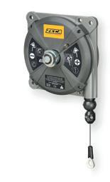
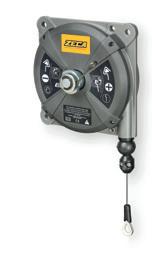
73 633.250 Rev . e BALANCERS –SAFETY INSTRUCTIONS MADE IN P .R.C. 12 1 2 3 2 load adjustment 633.250 Rev . e BALANCERS –SAFETY INSTRUCTIONS MADE IN P .R.C. 12 1 2 3 2 Description Balancer Balancer Balancer Balancer with anti-fall device Balancer with anti-fall device Balancer with anti-fall device Balancer with anti-fall device Balancer with anti-fall device ART. 620 621 622 623 624 625 626 627 Textile cable in polyethylenic fibre HT Capacity Kg 0,4 ÷ 1 1 ÷ 2 2 ÷ 3 2 ÷ 4 4 ÷ 6 6 ÷ 8 8 ÷ 10 10 ÷ 14 Travel mm 1600 1600 1600 2500 2500 2500 2500 2500 1 mm 170x125x70 Kg 0,7 mm 170x125x70 Kg 0,8 mm 170x125x70 Kg 0,9 mm 245x200x110 Kg 3,2 mm 245x200x110 Kg 3,3 mm 245x200x110 Kg 3,4 mm 245x200x110 Kg 3,5 mm 245x200x110 Kg 3,6 Description Balancer Balancer Balancer Balancer with anti-fall device Balancer with anti-fall device Balancer with anti-fall device Balancer with anti-fall device Balancer with anti-fall device ART. 630 631 632 633 634 635 636 637 Stainless steel support cable Capacity Kg 0,4 ÷ 1 1 ÷ 2 2 ÷ 3 2 ÷ 4 4 ÷ 6 6 ÷ 8 8 ÷ 10 10 ÷ 14 Travel mm 1600 1600 1600 2500 2500 2500 2500 2500 1 mm 170x125x70 Kg 0,7 mm 170x125x70 Kg 0,8 mm 170x125x70 Kg 0,9 mm 245x200x110 Kg 3,2 mm 245x200x110 Kg 3,3 mm 245x200x110 Kg 3,4 mm 245x200x110 Kg 3,5 mm 245x200x110 Kg 3,6 dimensions 113 93 15 93 8 113 30° 60 250 6 Series 630 - 631 - 632 load adjustment dimensions 162,5mm 6,4in 193mm 7,6in 162,5mm 6,4in 28mm 1,1in 192mm 7,6in 3mm 0,1in 0,4in10mm 30° 415mm 16,3in 8mm 0,3in 99,5mm 3,9in Series 633 - 634 - 635 - 636 - 637 162,5mm 6,4in 193mm 7,6in 162,5mm 6,4in 28mm 1,1in 192mm 7,6in 3mm 0,1in 0,4in10mm 30° 415mm 16,3in 8mm 0,3in 99,5mm 3,9in Series 633 - 634 - 635 - 636 - 637
BALANCERS
AIR BALANCERS
SPIRAL HOSE FOR BALANCERS
SPIRAL HOSE FOR BALANCERS
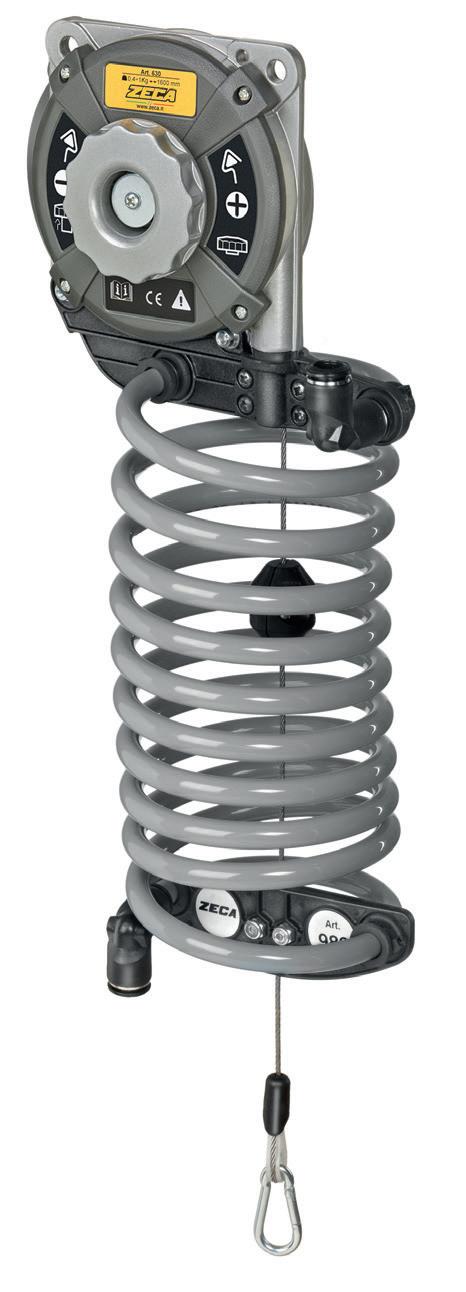
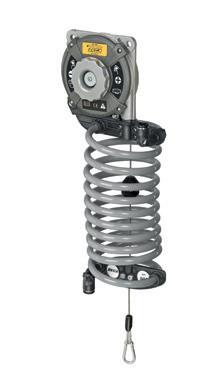
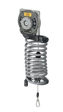
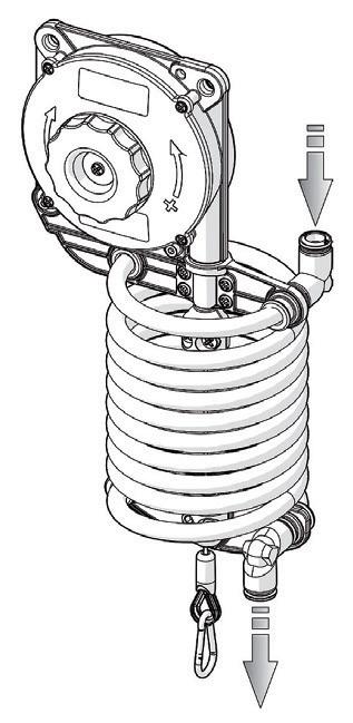
• Spiral hose (PA12) 8 x 10 for balancers.
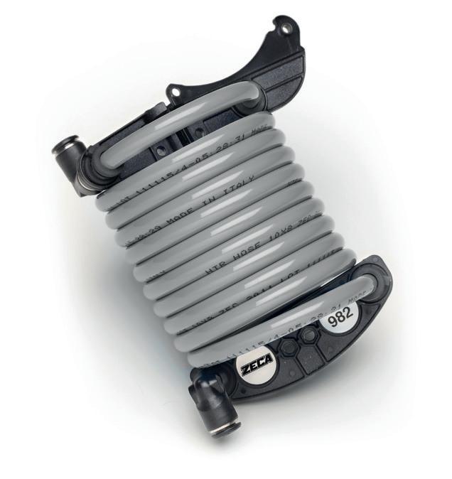
• Handy for hanging air-powered tools.
• The structure adapts to movements, increasing efficiency and productivity.
ART. 982
Spiral hose for use on balancers art. 620, 621, 622, 630, 631 and 632 Supplied with 1 m of additional hose for connection to the compressed air supply and tool. (Balancer not included).
SPIRALROHR FÜR
• Spiralrohr (PA12) 8 x 10 für Balancers Geeignet für die Aufhängung luftbetriebener Instrumente.
• Die Struktur passt sich den Bewegungen an, wodurch die Produktivität und Effizienz gesteigert werden.
ART. 982
Spiralrohr an Balancers einsetzbar Art. 620, 621, 622, 630, 631 und 632 Geliefert mit 1 m Zusatzrohr für den Anschluss an das Druckluftnetz und das Werkzeug. (Balancer nicht enthalten).
74
BALANCERS
Description Balancer + spiral hose Balancer + spiral hose Balancer + spiral hose ART. 630 AIR 631 AIR 632 AIR Stainless steel support cable Capacity Kg 0,40 ÷ 1 1 ÷ 2 2 ÷ 3 Travel mm 1600 1600 1600 Weight gr 630 670 790 1 mm 170x125x70 Kg 0,7 mm 170x125x70 Kg 0,8 mm 170x125x70 Kg 0,9 MAXIMUM PRESSURE: 10 BAR WORKING TEMPERATURE: -20° / +80° ■ EN ■ DE AIR BALANCERS

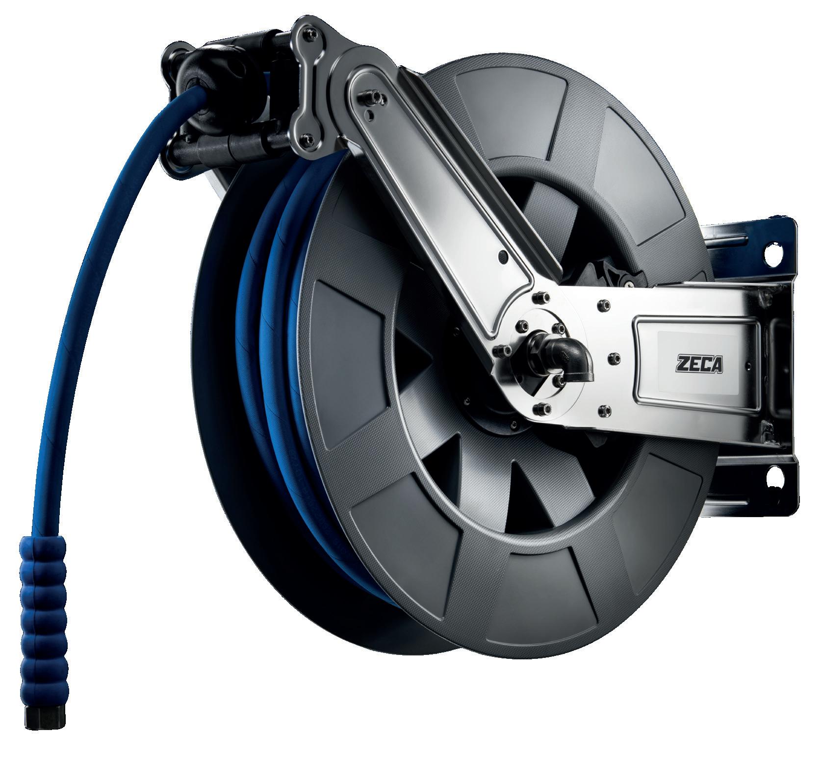
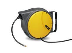
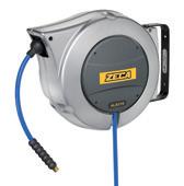
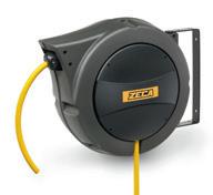
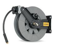
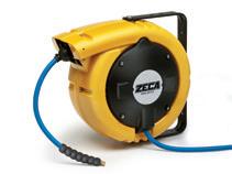
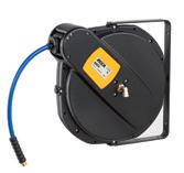
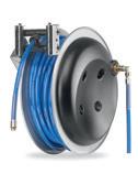
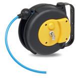
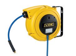
75 Hose Reels AM80 -AM85 series page 76 804 - 805 series page 78 AL series page 80 AM86 series page 82 8400 series page 85 813 series page 94 8800 series page 94 8900 series page 95 9100 series page. 95 480mm 18,9in 210mm 8,3in 225mm 8,9in 140mm 5,5in 200mm 7,9in 225mm 8,9in
NEW QUICK FIT SEE PAGE 12
SERIES AL41 / AL47 / AL48 / AL81
SERIE SERIE 375mm 14,8in 165mm 6,5in
TECHNICAL FEATURES
• Black polyurethane hose.
• Technopolymer casing.
• Complete with pivot bracket.
• Provided with hose ratchet stop device, easily removable if constant traction is required.

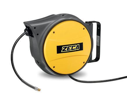
■ EN ■ DE 130mm 5,1in R145mm 5,7in
• Schwarzer Polyurethanschlauch.
• Technopolymer-Struktur
• Befestigungsbügel aus Metall, Verstellbar
• Automatische Vorrichtung zum Stoppen des Schlauchs auf der gewünschten Länge, evtl. trennbar.

FOR AM80 - ART. 949/AL41-AM40
Optional device to fasten the pivoting bracket. of AM80 reel.
Feststellvorrichtung, für die Serie AM80 als Optional lieferbar, um die Befestigungsbügel zu fixieren
FOR AM85 - ART. AL83-AM85/SR
See page / Siehe Seite 83
76 ART. AM80/8 AM85/8 AM85/10 Hose Int. Ø 8 mm (5/16”) 8 mm (5/16”) 10 mm (3/8”) Hose length 10 m 16 m 16 m Max press 15 bar 15 bar 15 bar End hose fitting 1/4” M BSP 1/4” M BSP 3/8” M BSP Temperature -5 °C/+40 °C -5 °C/+40 °C Incoming hose fitting NO NO Incoming hose 1,5 m 1,5 m Suitable for Air Air Hose type PU PU Hose color Black Black 40 20 1 mm 390x330X230 - Kg 4,5 mm 500x450x255 - Kg 8 dimensions AM80 dimensions AM85 490mm 19,3in R190mm 7,5in 170mm 6,7in 8mm 0,3in 205mm 8,1in AM85/AM70 2023 ISO EN 12100 2006/42/EU
AM80 AM80-AM85 SERIES
TECHNISCHE MERKMALE AM85 6mm 0,2in
■ OPTIONAL
KPU HOSE FLEX HOSE
KPU HOSE
Highly manageable, zero memory hose with reduced curvature. Lightweight and strong, it is ideal for all intensive uses, for conveying air or water.

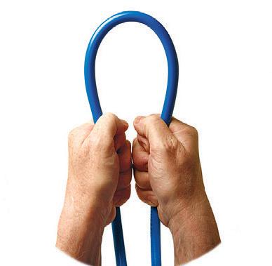
Temperature: -5 °C/+50 °C
ULTRA-FLEXIBLE HOSE FOR VEHICLE BODYWORK
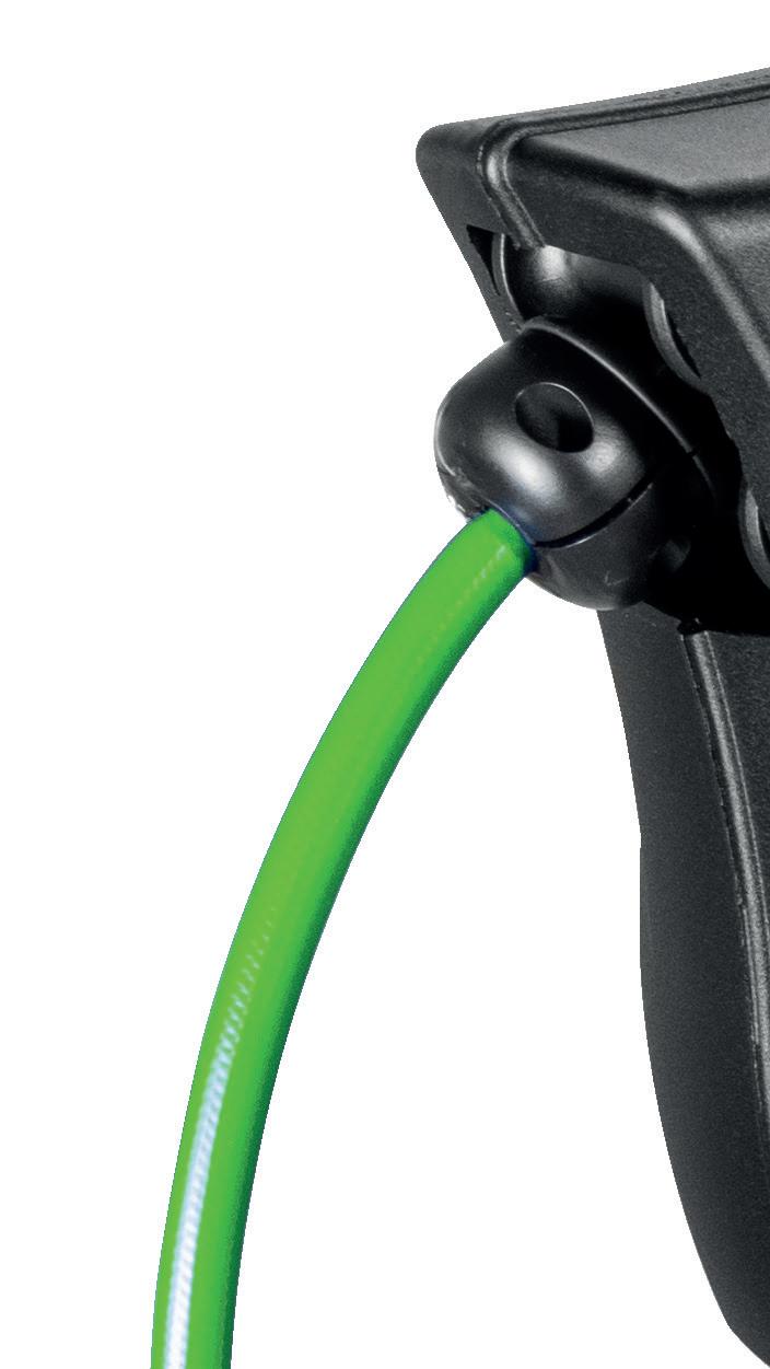
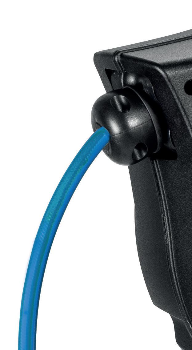
Suitable for intensive, daily use in vehicle bodywork shops and all working environments where a flexible, lightweight hose is essential. The zero memory effect minimises the risk of accidental collision with object, and the antistatic compound does not attract dust and paint particles.
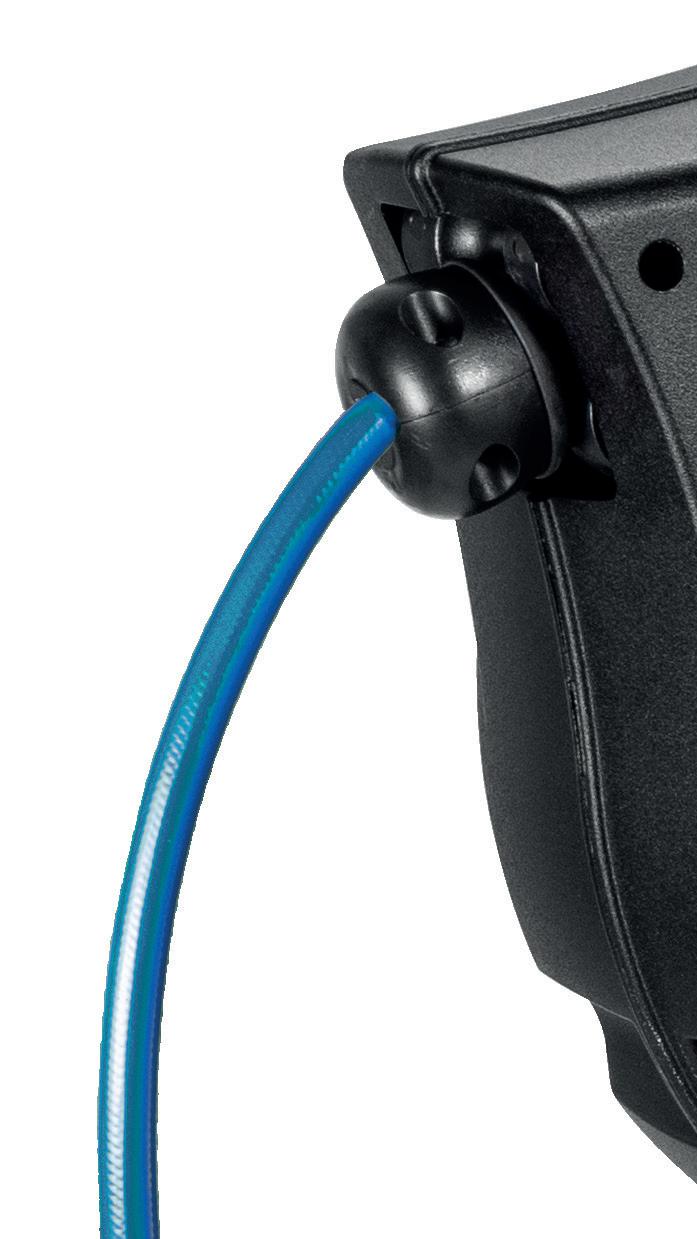
Fluids: air or water. Temperature: -5 °C/+60 °C
HIGHLY VISIBLE AND VIBRANT LIME GREEN HOSE

It stands out and can be easilydiscerned in dimlylit environments, reducingthe riskoftrippingIn situationswhere it is necessary to leave the hose unwound, it ensures order and minimises the riskofwearand damagetothe pipe.
Fluids: air or water. Temperature: -5 °C/+50 °C
77 AL BLACK SERIES
ZEROMEMORY
ANTISTATIC SILICONFREE NEW NEW KPUHOSE
SAFE HOSE
EFFECT HIGHLYVISIBLE
STAIRFLOW KPUHOSE
Art. 804 1 1 ISO EN 12100 2006/42/EU
44 mm 360x310x185 - Kg 4
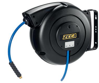
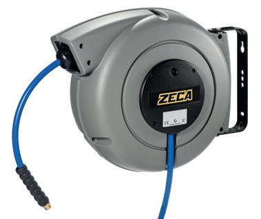
ART. 949/804-4000 ART. 949/805-7000 Art. 805 mm 430x400x210 - Kg 7
78 ART. BLACK 804/8/B 804/10/B 805/8/B 805/10/B 805/13/B ART. SILVER 804/8/S 804/10/S 805/8/S 805/10/S 805/13/S ART.YELLOW 804/8 804/10 805/8 805/10 805/13 Hose Int. Ø 8 mm (5/16”) 10 mm (3/8”) 8 mm (5/16”) 10 mm (3/8”) 12,5 mm (1/2”) Hose length 10 m 8 m 16 m 16 m 11 m Max press 15 bar End hose fitting 1/4” M BSP 3/8” M BSP 1/4” M BSP 3/8” M BSP 1/2” M BSP Temperature -5 °C/+50 °C Incomingfittinghose NO Incoming hose 1,5 m Suitable for Air - Water Hose type KPU Hose color BLU 804 - 805 SERIES
Optional device to fasten the pivoting bracket. Feststellvorrichtung, als Optional lieferbar, um die Befestigungsbügel zu fixieren. ■ OPTIONAL 20
TECHNICAL FEATURES
• Technopolymer casing.
• Complete with pivot bracket.
• Provided with hose ratchet stop device, easily removable if constant traction is required.
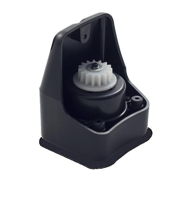
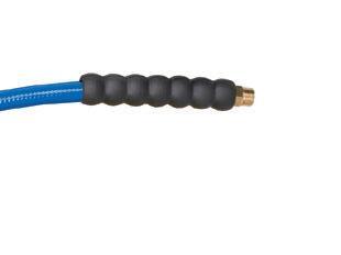

• KPU hose.
• KPU-Schlauch
• Struktur aus Technopolymer
• Austrichtbarer Befestigungsbügel aus Metall.
• Verfügbar in den Farben Gelb, Silbergrau und Schwarz.
• Automatische Vorrichtung zum Stoppen des Schlauchs auf der gewünschten Länge, evtl. trennbar.
■ OPTIONAL
ART. 805/SR
AN EXTRA GUARANTEE WITH
The Safety Return braking system slows the retraction of the hose into the case, preventing kickback should the hose accidentally slip out of the user’s hand. Safety Return is an optional braking device for the Zeca 805 series.
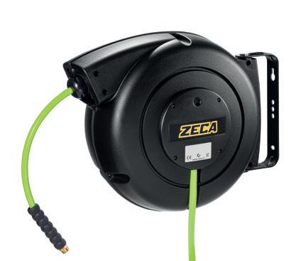
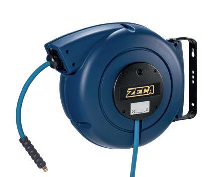
Das Safety Return-Bremssystem ermöglicht das langsame Zurückspulen des Schlauchs in das Gehäuse und vermeidet Rückschläge, wenn der Schlauch versehentlich aus der Hand des Bedieners entweicht. Safety Return ist eine optionale Bremsvorrichtung Für die Serie Zeca 805.
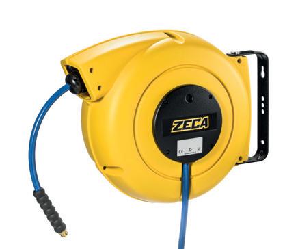
79 ART. 805/8 FLEX 805/10 FLEX 805/8/A FLEX 805/10/A FLEX 805/8/B SAFE 805/10/B SAFE Hose Int. Ø 8 mm (5/16”) 10 mm (3/8”) 8 mm (5/16”) 10 mm (3/8”) 8 mm (5/16”) 10 mm (3/8”) Hose length 15 m 15 m 15 m 15 m 16 m 16 m Max press 15 bar End hose fitting 1/4” M BSP 3/8” M BSP 1/4” M BSP 3/8” M BSP 1/4” M BSP 3/8” M BSP Temperature -5 °C/+60 °C -5 °C/+50 °C -5 °C/+50 °C Incomingfittinghose NO Incoming hose 1,5
for Air - Water Hose type FLEX KPU SAFE Hose color LIGHT BLUE LIME GREEN
804 - 805 SERIES
m Suitable
804 - 805 SERIE
TECHNISCHE MERKMALE ■ EN ■ DE KPUHOSE STAIRFLOW 3 YEARS WARRANTY BEST
SELLERS
PREVENTSRAPID RETRACTION NEW QUICK FIT SEE PAGE 12
5
AL81 SERIE ALUMINIUM BODY ALUMINIUM BODY
■ OPTIONAL
PREVENTSRAPID RETRACTION
■ EN
■ DE Safety Return slows the retraction of the hose, preventing kickback should the hose accidentally slip out of the user’s hand. Safety Return is an optional braking device for AL83 series.

DE Safety Return ermöglicht das langsame Zurückspulen des Schlauchs und vermeidet gefährliche Rückschläge, falls der Schlauch aus der Hand des Bedieners fällt. Safety Return ist eine optionale Bremsvorrichtung für die AL83-Serie.
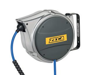
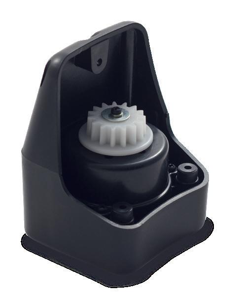
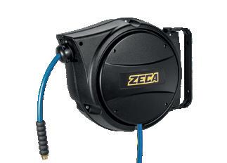

80 AL81/8 AL81/10 ART. AL81/8/B AL81/10/B AL81/8/B FLEX AL81/8/B SAFE AL81 /10/B SAFE Ø internal hose 8 mm (5/16”) 10 mm (3/8”) 8 mm (5/16”) 8 mm (5/16”) 10 mm (3/8”) Pipe.length (m) 10 m 8 m 8 m 10 m 8 m Max press. 15 bar 15 bar 15 bar 15 bar 15 bar Outlet fitting 1/4” M BSP 3/8” M BSP 1/4” M BSP 1/4” M BSP 3/8” M BSP Temperature -5 °C/+50 °C -5 °C/+60 °C -5 °C/+50 °C Incomingfittinghose NO Incoming hose 1,5 m Suitable for Air - Water Hose type KPU FLEX KPU SAFE Hose colour BLUE LIGHT BLUE LIME GREEN 44 1 mm 360x310x185 - Kg 6,0 ISO EN 12100 2006/42/EU AL SERIES
ART. AL83-AM85/SR
AN EXTRA GUARANTEE WITH YEARS WARRANTY
• Die-cast aluminium casing painted with black epoxy powders.
• Metal, adjustable fastening bracket.
• Provided with hose ratchet stop device, easily removable if constant traction is required.
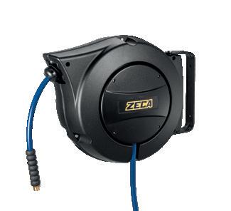
• KPU: with extra-strong hose for heavy duty environments
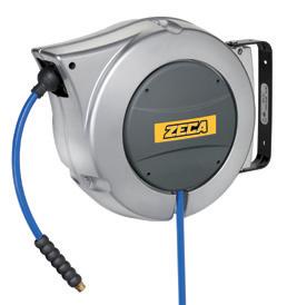
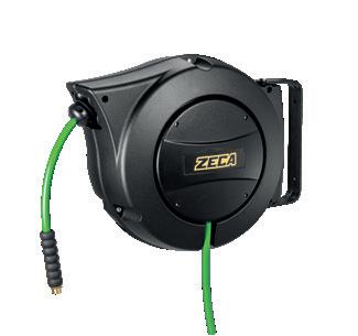
• FLEX: with ultra-flexible, antistatic and silicone-free hose
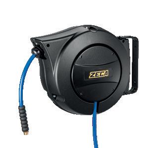
• SAFE: lime green KPU hose.
• Struktur aus lackiertem Aluminiumdruckguss mit schwarzem Epoxidpulver.
• Austrichtbarer Befestigungsbügel aus Metall.
• Automatische Vorrichtung zum Stoppen des Schlauchs auf der gewünschten Länge, die bei Bedarf getrennt werden kann
• KPU: mit widerstandsfähigem Schlauch für Heavy-Duty-Umgebungen
• FLEX: mit Schlauch ultraflexibel, antistatisch und silikonfrei
• SAFE: limettengrüner KPU-Schlauch.
81 dimensions AL83 Ø6mm Ø0,2in 160mm 6,3in 490mm 19,3in R190mm 7,5in 210mm 8,3in AL83 dimensions AL81 6mm 0,2in 130mm 5,1in R145mm 5,7in 375mm 14,8in 165mm 6,5in
AL SERIES
SERIES AL41 / AL47 / AL48 / AL81
TECHNICAL FEATURES TECHNISCHE MERKMALE ■ EN ■ DE ART. AL83/8/B AL83/10/B AL83/13 AL83/8/B FLEX AL83/10/B FLEX AL83/8/B SAFE AL83/10/B SAFE Ø internal hose 8 mm (5/16”) 10 mm (3/8”) 12,5 mm (1/2”) 8 mm (5/16”) 10 mm (3/8”) 8 mm (5/16”) 10 mm (3/8”) Pipe.length (m) 16 m 11 m 15 m 16 m Max press. 15 bar 15 bar 15 bar Outlet fitting 1/4” M BSP 3/8” M BSP 1/2” M BSP 1/4” M BSP 3/8” M BSP 1/4” M BSP 3/8” M BSP Temperature -5 °C/+50 °C -5 °C/+60 °C -5 °C/+50 °C Incomingfittinghose NO Incoming hose 1,5 m Suitable for Air - Water Hose type KPU FLEX KPU SAFE Hose colour BLUE LIGHT BLUE LIME GREEN 20 1 mm 450x390x215 - Kg 9
AL83 SERIE
Compliant with Directives 2014/34/EU
Marking
II 2 GD c IIB T4/T135° C X
Examination Certificate Number for IMQ 14 ATEX 009 X
Compliant with Standards EN 13463-1 : 2009 | EN 13463-5 : 2011
FIELDS OF USE
■ EN ■ DE
TECHNICAL FEATURES
• Metal, adjustable fastening bracket.
• Provided with hose ratchet stop device, easily removable if constant traction is required.
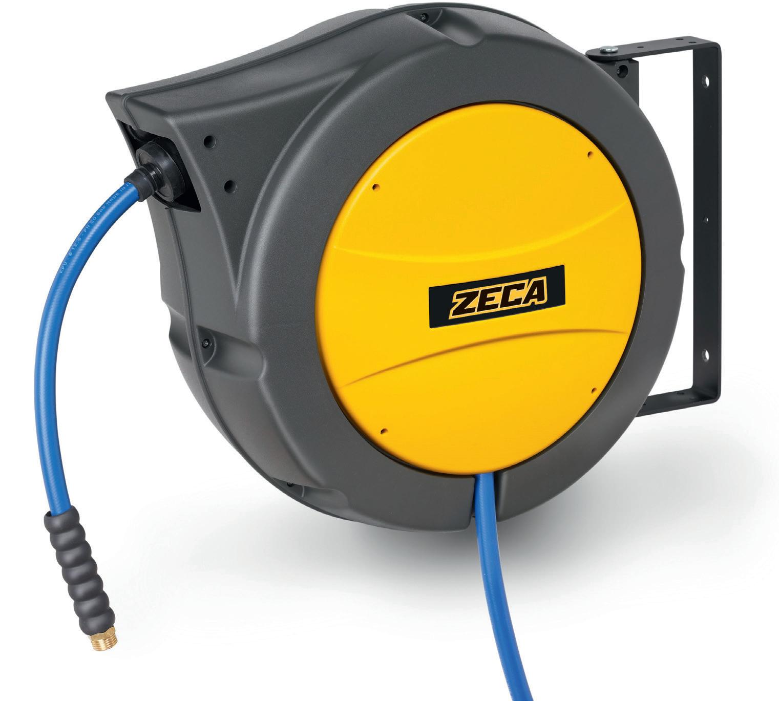
Can be supplied with:
KPU hose. Technopolymer structure.
PVC, soft touch, scuff-resistant hose
NBR (SAE 100R6) extra-strong hose.
TECHNISCHE MERKMALE
• Austrichtbarer Befestigungsbügel aus Metall.
• Automatische Schlauchhaltevorrichtung mit der gewünschten Länge, evtl. trennbar.
Kann geliefert werden mit:
KPU-Schlauch Struktur aus Technopolymer.
Abriebfester Soft-Touch
PVC-Schlauch.
NBR-Schlauch (SAE 100R6) extrem widerstandsfähig.
82 AL SERIES
AM86
I NDUSTRY
CARREPAIR WORKSHOP AGRICULTURE STAIRFLOW
ISO EN 12100 2006/42/EU
■ EN Safety Return slows the retraction of the hose, preventing dangerous kickback should the hose accidentally slip out of the user’s hand. Safety Return is an optional braking device for the AM86 series
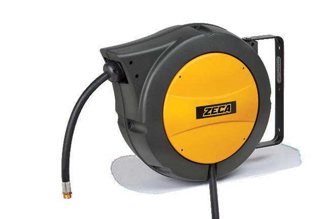
■ DE Safety Return ermöglicht das langsame Zurückspulen des Schlauchs und vermeidet gefährliche Rückschläge, falls der Schlauch aus der Hand des Bedieners fällt. Safety Return ist eine optionale Bremsvorrichtung für die gesamte AM83-Serie.
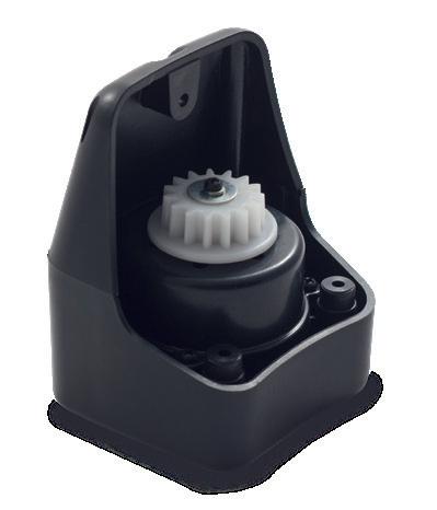
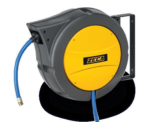
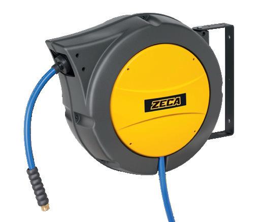
83 AM86 SERIES
dimensions AM86 ART. AM86/10 AM86/13 AM86/10 PVC AM86/13 PVC AM86/10 NBR AM86/13 NBR Hose Int. Ø 10 mm (3/8”) 12,5 mm (1/2”) 10 mm (3/8”) 12,5 mm (1/2”) 10 mm (3/8”) 12,5 mm (1/2”) Hose length 25 m 16 m 20 m 12 m 18 m 12 m Max press 15 bar 15 bar 15 bar 15 bar 15 bar 15 bar End hose fitting 3/8” M BSP 1/2” M BSP 3/8” M BSP 1/2” M BSP 3/8” M BSP 1/2” M BSP Incomingfittinghose NO NO NO Temperature -5 °C/+50 °C -5 °C/+50 °C -5 °C/+50 °C Incoming hose 1,5 m 1,5 m 1,5 m Suitable for Air - Water Air - Water Air - Water Hose type KPU PVC SAE 100R6 Hose color BLUE BLUE BLACK Atex -R230mm 9,1in 10,5mm 0,4in 565mm 22,2in 250mm 9,8in 235mm 9,3in 14 mm 550x505x270 Kg 10 1
AM86 kpu AM86 pvc AM86 nbr
■ OPTIONAL ART. AM86/SR
AM86/AGRI
■ OPTIONAL ART. AM86/FT
■ EN
Fittings kit for agricultural hoses including:
• Incoming hose fitting
• End hose fitting with “Water Stop” system
Tested up to 6 bar
■ DE
FITTINGSsatz für AgriSchläuche bestehend aus:
• Eingangsfitting
• End hose fitting mit „ Water Stop“-System Getestet bis 6 bar
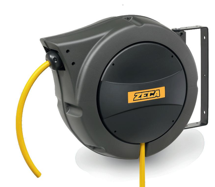
TECHNICAL FEATURES ■ EN
AGRI hose for professional agricultural sector
• Technopolymer casing.
• Metal, adjustable fastening bracket.
• Provided with hose ratchet stop device, easily removable if constant traction is required.
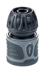
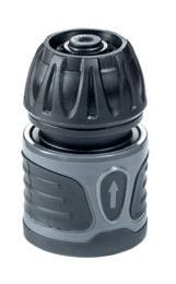
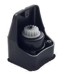
TECHNISCHE MERKMALE ■ DE
AGRI-Schlauch für den Landwirtschaftssektor
• Struktur aus Technopolymer.
• Austrichtbarer Befestigungsbügel aus Metall.
• Automatische Schlauchhaltevorrichtung mit der gewünschten Länge.Evtl. trennbar.
ART. AM86/SR
■ EN
See page 83
■ DE
Siehe Seite 83
84 AM86 FOOD
R230mm 9,1in 10,5mm 0,4in 565mm 22,2in 250mm 9,8in 235mm 9,3in dimensions AM86 ART.
Hose Int. Ø 12,5 mm (1/2”) Hose
18
End hose fitting NO Temperature +5 °C/+40 °C Incoming hose fitting NO Incoming hose 1,5 m Suitable for Water Hose type PVC Hose color YELLOW 14 1 mm 550x505x270 - Kg 10 ISO EN 12100 2006/42/EU
AM86/AGRI
length
m Max press 6 bar (0,6 Mpa)
F O R PROFESSIONAL USE
Self-lubricated ROLLER GUIDE
SERIES 8400

SWIVELING BRACKET to adapt to any type of installation
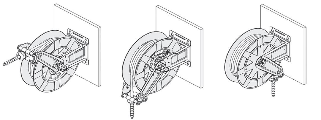
Adjustable hose stopper
RECOIL SPRING with maximo process technology.
ROTATING JOINT
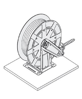
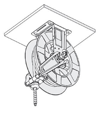
• with low friction
• without narrowing
Hose ratched stop device for the hose at the required length.
85
ABS DRUM
DRUM SUPPORTING
with
BUSHINGS made
self-lubrificating material.
Ød ØD TPE ABS SERIES 943 CODE ØD (mm) Ød (mm) Ø - HOSE (mm) CABLE 943/1 48 6 6,5 7,5 943/2 48 7,5 8 9 943/3 48 9 9,5 - 11 943/4 48 11 11,5 - 13 943/5 48 13 13,5 15 SERIES 944 944/1 61 13 13,5 15 944/2 61 14 14,5 16 944/3 61 16 16,5 18 944/4 61 18 18,5 20 944/5 61 25 25 26 ADJUSTABLE HOSE STOPPER (see p. 169) ■ INSTALLATION 225 225 20 250 250 210 225 110 225 225 20 250 250 210 225 110 ■ INSTALLATION WALL-MOUNTED CEILING-MOUNTED BENCHTOP ■ SUITABLE FOR WATER HIGH-PRESSURE WATER OIL AIR GREASE DIESEL 8400
End pipe fitting in brass/steel
Steel coil shaft
ADJUSTABLE HOSE STOPPER
ABS DRUM Brackets in steel, painted with epoxy resin powder
FPM Gasket
Steel screws and bolts
Stainless steel AISI 304 rotating shaft (in brass for low pressure models)
Brass ring nut
PTFE Rod guide ring
Compliant with Directives 2014/34/EU
Marking
II 2 GD c IIB T4/T135° C X
Examination Certificate Number for IMQ 14 ATEX 009 X
Compliant with standards EN 13463-1: 2009 | EN 13463-5: 2011
PTFE Rod guide ring
Axial roller bearing
Brass bushing incoming fitting in brass
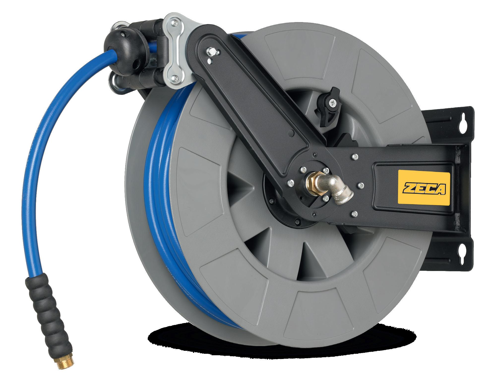
86 8400 SERIES 18 480mm 18,9in 210mm 8,3in 16,7in425mm 225mm 8,9in 110mm 4,3in 140mm 5,5in 200mm 7,9in 225mm 8,9in 185mm 7,3in
14 mm 550x505x270 Kg 10 1
ISO EN 12100 2006/42/EU
8400
dimensions 8400
■ EN
* REG. UE 1935/2004AND REG. UE 10/2011 certified hose for use inthefood industry. Not suitableforfood liquidstransfer.
■ DE
*NOTE:* Schlauch zertifiziert nach VERORD. EU 1935/2004 und VERORD. EU 10/2011, d. h. geeignetfürden Kontakt mit Lebensmitteln. NichtfürLebensmittelflüssigkeiten geeignet.
87 8400 SERIES Max press Suitable for Hose type Hose Int. Ø Hose length Art. Fluid Temperature End pipe fitting Incoming fitting 20 bar Air Water NO HOSE / / 8401 / -15°C/+50°C 1/2” F 1/2” F / / 8480 AISI 316L joint SAE 100R6 6 mm (1/4”) 20 8412 / 1/4” M 8 mm (5/16”) 20 8402 / 10 mm (3/8”) 12 8404 3/8” M 10 mm (3/8”) 18 8406 12,5 mm (1/2”) 10 8408 1/2” M 12,5 mm (1/2”) 15 8410 KPU 10 mm (3/8”) 20 8424 3/8” M 12,5 mm (1/2”) 15 8426 1/2” F 12,5 mm (1/2”) 20 8427 15 bar Water PU-FOOD QUALITY* 12,5 mm (1/2”) 12 8432 / -10°C/+60°C 1/2” M 1/2” F Diesel Oil PVC - PU 19 mm (3/4”) 8 8415 / -10°C/+60°C 3/4” F swivelling 3/4” M Ad Blue 19 mm (3/4”) 8 8482 AISI 316L joint 160 bar Oil EN 857 1SC 12,5 mm (1/2”) 10 8474 / -15°C/+120°C 1/4” F swivelling 3/8” F 200 bar Oil Water NO HOSE / / 8440 / -15°C/+130°C 1/2” F EN 857 1SC Nero 8 mm (5/16”) 20 8441 / 3/8” F swivelling 180 bar 10 mm (3/8”) 15 8442 10 mm (3/8”) 18 8443 EN 857 1SC Blu Non Marking 10 mm (3/8”) 15 8446 10 mm (3/8”) 18 8448 400 bar Oil Grease NO HOSE / / 8460 / -20°C/+120°C 1/2” F 3/8” F EN 857 2SC 6 mm (1/4”) 12 8462 / 1/4” M 18 8463 / 1/4” M
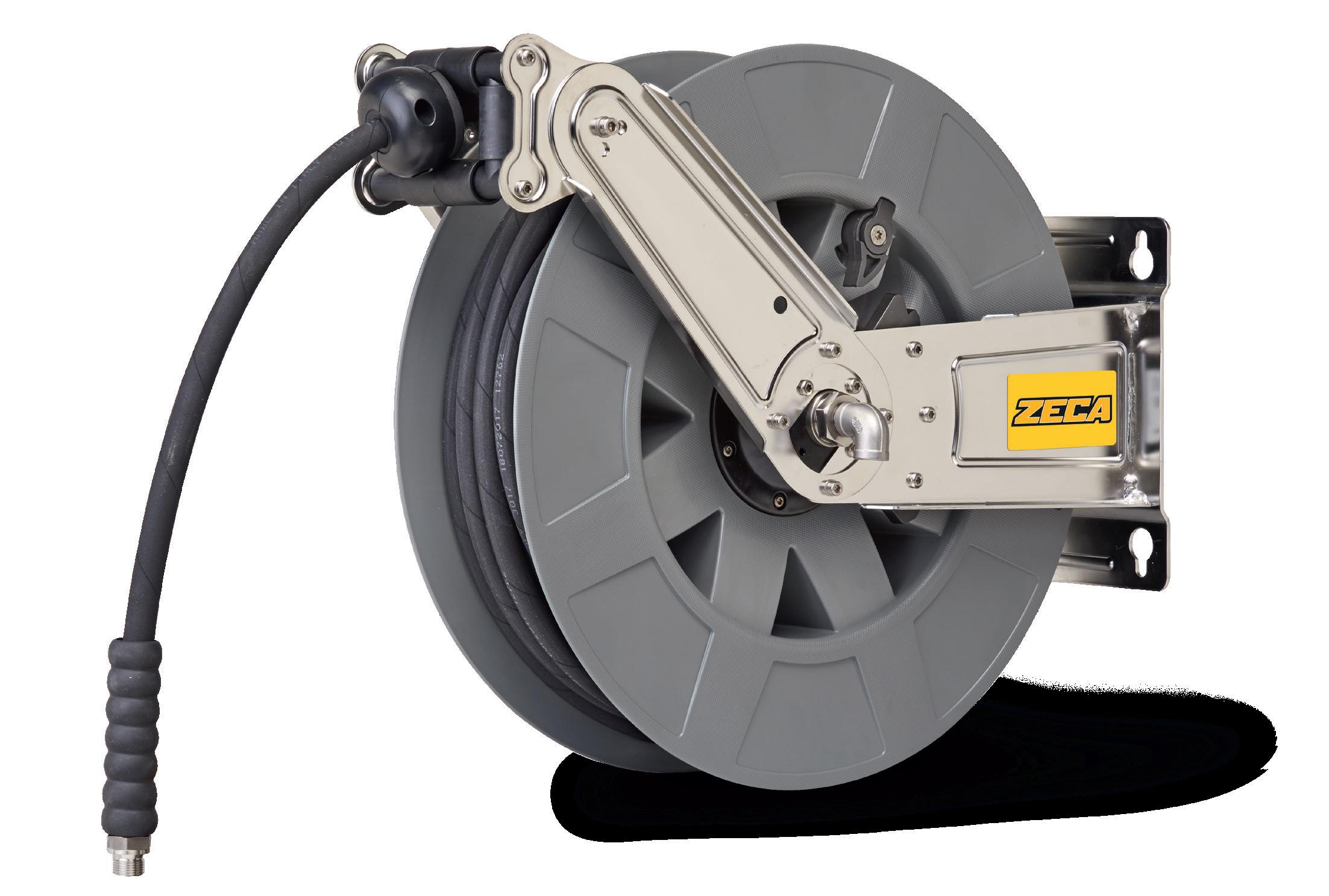
88 8400 SERIES
1 dimensions 8400 480mm 18,9in 210mm 8,3in 16,7in425mm 225mm 8,9in 110mm 4,3in 140mm 5,5in 200mm 7,9in 225mm 8,9in 185mm 7,3in ISO EN 12100 2006/42/EU
14 mm 550x505x270 Kg 10
Incoming fitting in brass
Brass ring nut
Steel coil shaft
Bracket in stainless steel AISI 304
stainless steel AISI 316L screws and bolts
End pipe fitting in brass/steel
PTFE Rod guide ring
PTFE Rod guide ring
FPM Gasket Axial roller bearing
ABS DRUM ADJUSTABLE HOSE STOPPER
Bushing in brass
8400 LIGHT INOX
Stainless steel AISI 304 rotating shaft (in brass for low pressure models)
The Light Stainless steel hose reels are suitable for different fields of application, from the food industry to the shipping and chemical sectors, aggressive work environments with corrosive atmospheres. Ideal for industrial cleaning, blowing operations and for conveying fluids like oil.
Schlauchaufroller Light EDELSTAHL eignen sich für verschiedene Einsatzbereiche, von der Lebensmittelindustrie über die Schifffahrt und Chemie bis hin zu aggressiven Arbeitsumgebungen und korrosiven Atmosphären. Ideal für die industrielle Reinigung, Blasarbeiten und den Transport von Flüssigkeiten wie z. B. Öl.
■ EN
* REG. UE 1935/2004AND REG. UE 10/2011 certified hose for use inthefood industry. Not suitableforfood liquidstransfer.
■ DE
*NOTE:* Schlauch zertifiziert nach VERORD. EU 1935/2004 und VERORD. EU 10/2011, d. h. geeignetfürden Kontakt mit Lebensmitteln. NichtfürLebensmittelflüssigkeiten geeignet.
89 8400 SERIES Max press Fluid type Hose type Hose Int. Ø Hose length Art. Fluid Temperature End pipe fitting Incoming fitting 20 bar Air Water NO HOSE / / 8401/1003 -15°C/+50°C 1/2” F 1/2” F SAE 100R6 10 mm (3/8”) 12 8404/1000 3/8” M 10 mm (3/8”) 18 8406/1000 KPU 12,5 mm (1/2”) 15 8426/1002 1/2” M 12,5 mm (1/2”) 20 8427/1002 15 bar Water PU FOOD QUALITY* 12,5 mm (1/2”) 12 8432/1001 -10°C/+60°C 1/2” M 1/2” F 180 bar Oil Water NO HOSE / / 8440/1003 -15°C/+130°C 1/2” F 3/8” F EN 857 1SC Black 10 mm (3/8”) 15 8442/1000 3/8” F swivelling 10 mm (3/8”) 18 8443/1000 EN 857 1SC Blue No Marking 10 mm (3/8”) 15 8446/1000 10 mm (3/8”) 18 8448/1000
■ EN ■ DE
TECHNICAL FEATURES TECHNISCHE MERKMALE
90 480mm 18,9in 210mm 8,3in 16,7in425mm 225mm 8,9in 110mm 4,3in 140mm 5,5in 200mm 7,9in 225mm 8,9in 185mm 7,3in 14
10 1 dimensions 8400 ISO EN 12100 2006/42/EU
mm 550x505x270 Kg
Incoming fitting in stainless steel AISI 316L
Rotating shaft in stainless steel AISI 304
Stainless steel AISI 304 ring nut
Coil shaft in stainless steel AISI 304
Bracket in stainless steel AISI 304
Screws and bolts in stainless steel AISI 316L
End pipe fitting in stainless steel AISI 316L
PTFE Rod guide ring
PTFE Rod guide ring
FPM Gasket
Axial roller bearing
ABS DRUM ADJUSTABLE HOSE STOPPER 8400 SERIES 8400
Bushing in stainless steel AISI 304
FULL INOX
TECHNICAL FEATURES
Full STAINLESS STEEL reels are the ideal for transport of fluids such as oil, AdBlue® , air and water, for industrial cleaning and blowing operations. They are perfect for different applications: food and drink industry, boating industry, chemical sector, heavy duty work environments.and corrosive atmosphere.
Schlauchaufroller Full EDELSTAHL eignen sich für verschiedene Einsatzbereiche, von der Lebensmittelindustrie über die Schifffahrt und Chemie bis hin zu aggressiven Arbeitsumgebungen und korrosiven Atmosphären. Ideal für die industrielle Reinigung, Blasarbeiten und den Transport von Flüssigkeiten wie z. B. Öl und AdBlue®
■ EN
* REG. UE 1935/2004AND REG. UE 10/2011 certified hose for use inthefood industry. Not suitableforfood liquidstransfer.
■ DE
*NOTE:* Schlauch zertifiziert nach VERORD. EU 1935/2004 und VERORD. EU 10/2011, d. h. geeignetfürden Kontakt mit Lebensmitteln. NichtfürLebensmittelflüssigkeiten geeignet.
91 Max press Suitable for Hose type Hose Int. Ø Hose length Art. Fluid Temperature End pipe fitting Incoming fitting 20 bar Air Water NO HOSE / / 8401/1113 -15°C/+50°C 1/2” F 1/2” F SAE 100R6 10 mm (3/8”) 12 8404/1111 3/8” M 10 mm (3/8”) 18 8406/1111 KPU 12,5 mm (1/2”) 15 8426/1111 1/2” M 12,5 mm (1/2”) 20 8427/1111 15 bar Water PU FOOD QUALITY* 12,5 mm (1/2”) 12 8432/1111 -10°C/+60°C 1/2” M 1/2” F 15 bar AD Blue® PVC-PU 19 mm (3/4”) 8 8482/1111 -10°C/+60°C 3/4” F swivelling 3/4” M 180 bar Oil Water NO HOSE / / 8440/1113 -15°C/+130°C 1/2” F 3/8” F EN 857 1SC Nero 10 mm (3/8”) 15 8442/1111 3/8” F swivelling 10 mm (3/8”) 18 8443/1111 EN 857 1SC Blu Non Marking 10 mm (3/8”) 15 8446/1111 10 mm (3/8”) 18 8448/1111
TECHNISCHE MERKMALE ■ EN ■ DE
8400 SERIES
OPTIONAL SERIE 8400
COIL COVER
ART. 8400/CY
■ EN Yellow coil cover
■ DE Gelbe Spulenabdeckung
ART. 8400/CB
■ EN Black coil cover
■ DE Schwarze Spulenabdeckung
SWIVEL BRACKET
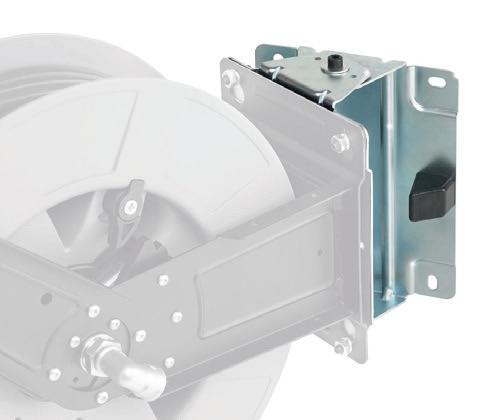
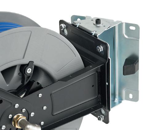
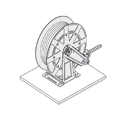
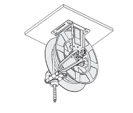
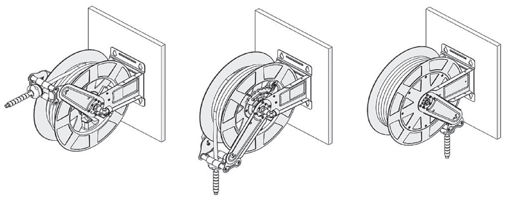
ART. 8400/SW
■ EN Swivel bracket
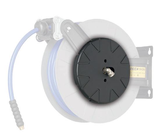
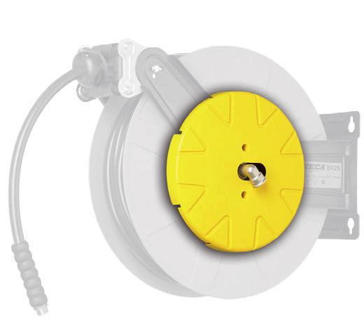
■ DE Verstellbare Halterung
ART. 8400/SWI
■ EN Stainless steel swivel bracket
■ DE Verstellbare Halterung aus Edelstahl
INLET HOSE
POSSIBLE INSTALLATION
WALL INSTALLATION
CEILING INSTALLATION
BENCH INSTALLATION
92
ART. 8400/SL Inlet hose 60 cm - 20 bar - 1/2” SAE 100 R6 - fittings 1/2” M and 1/2” F rotating ART. 8400/SK Inlet hose 60 cm - 20 bar - 1/2” KPU - fittings 1/2” M and 1/2” F rotating ART. 8400/SH Inlet hose 60 cm - 200 bar - 3/8” 1SC black - fittings 3/8” M and 3/8” F rotating 8400 SERIES
Water jet width
Low pressure water gun with adjustable spray
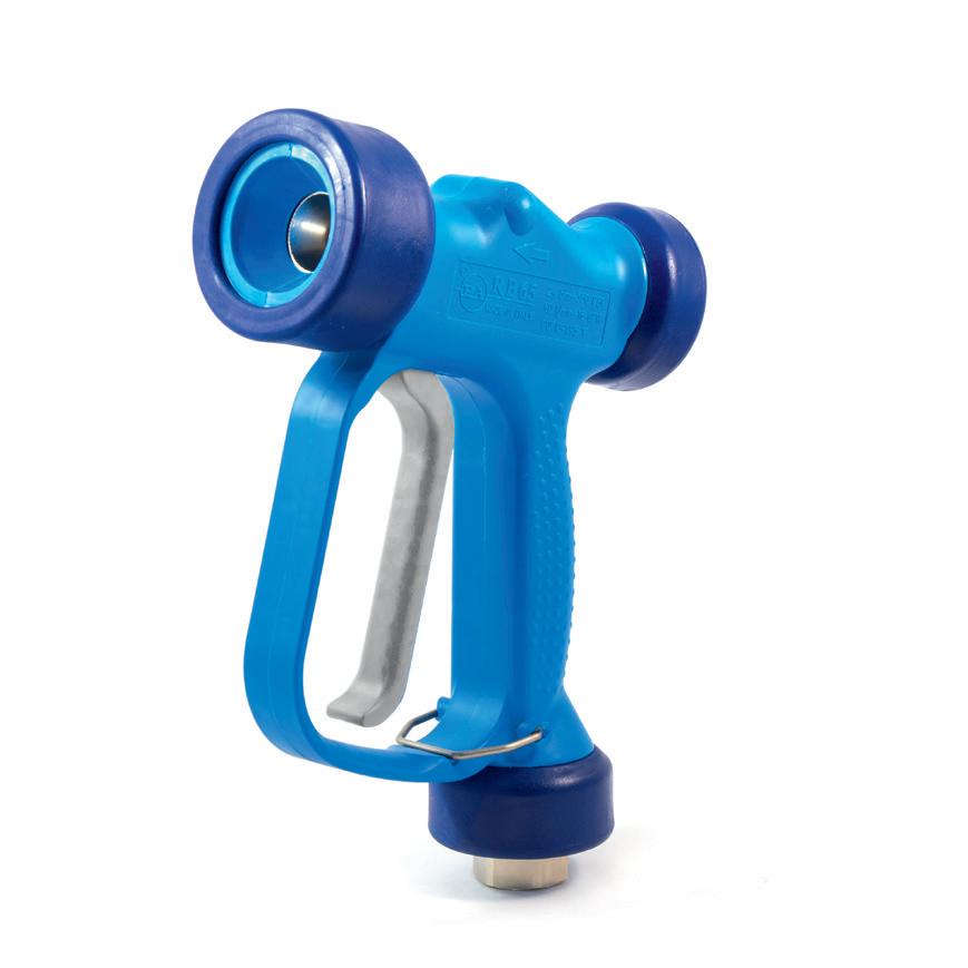

Adjustment by handle: - fully pulled lever: needle jet - lever released: 60° cone jet
Adjustment screw ranging cone width from 0° to 60° Adjustment screw ranging cone width from 0° to 60°
Automatic refueling nozzle
ART. KPE060 D Automatic refueling nozzle for gasoline 60 l/min
ART. KPE090 D Automatic refueling nozzle for gasoline 90 l/min
ART. KPE060 U Automatic refueling nozzle for AdBlue® 60 l/min
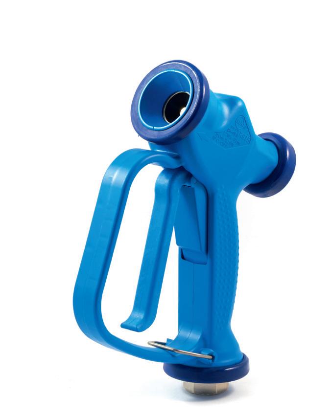
■ EN Not suitable for gas, petrol, oil, alcohol and water.
■ DE Nicht geeignet für Gas, Benzin, Öl, Alkohol und Wasser
93 KPW050 KPW060 KPW060I Material body PP + GF PP + GF PP + GF Material piston Brass Brass Inox Aisi 316 Material gasket Viton Viton Viton Max. flow rate 50 l/min 60 l/min 60 l/min Nominal pressure 12 bar / 1.2 MPa 24 bar / 2.4 MPa 24 bar / 2.4 MPa Max working temp. 50 °C /120 °F 60°C /140 °F 60°C/140 °F Incoming fitting Swivel G 1/2“F Swivel G 1/2“F Swivel G 1/2“F
ZETEK WATER GUNS
ALUMINIUM
BODY ALUMINIUM BODY
TECHNICAL FEATURES
• Hose in dual material PVC/PU, matt blue.
• Casing in die-cast aluminium with epoxy powder coating.
• Metal, adjustable fastening bracket.
• Provided with hose ratchet stop device, easily removable if constant traction is required.
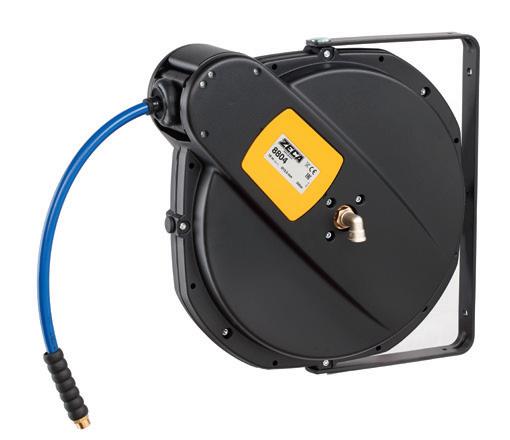
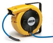
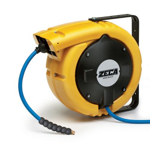
TECHNISCHE MERKMALE ■ DE
• Schlauch aus zwei Materialien PVC/PU, mattblau.
• Struktur aus lackiertem Aluminiumdruckguss mit Epoxidpulver.
• Austrichtbarer Befestigungsbügel aus Metall.
• Automatische Schlauchhaltevorrichtung mit der gewünschten Länge, evtl. trennbar.
■ OPTIONAL ART. 949/PR
■ EN Optional device to fasten the pivoting bracket.
■ DE Feststellvorrichtung, als optional lieferbar, um die Befestigungsbügel zu fixieren.
■ EN Roller-cable guide, necessary for ceiling applications.
■ DE Rollenmundstück, nötig für Deckenmontage.
■ EN
TECHNICAL FEATURES
• Hose stop device at the desired length; can be disabled.
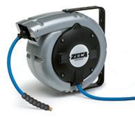
• Brass/stainless steel rotating joint.
Suitable
TECHNISCHE
MERKMALE
• Vorrichtung zum Stoppen des Schlauchs auf der gewünschten Länge, evtl. trennbar.
• Drehgelenk aus Messing/Edelstahl.
94 813 SERIES 8800 SERIES 813 dimensions 813 ART. SILVER 813/8/S 813/10/S ART. YELLOW 813/8 813/10 Hose Int. Ø 8 mm (5/16”) 10 mm (3/8”) Hose length 12 m 9 m Max press 12 bar 12 bar End hose fitting 1/4” M BSP 3/8” M BSP Temperature -5 °C/+40 °C Incomingfittinghose 1/4” M 3/8” M Incoming hose 2 m Suitable for Air - Water Hose type PVC / PU Hose color BLUE 30 1 mm 400x370x190 - Kg 10,5 ISO EN 12100 2006/42/EU
■ EN
ART. 8803 8804 Hose Int. Ø 10 mm (3/8”) 12 mm (1/2”) Hose length 21 m 16 m Max press 20 bar 20 bar End hose fitting 3/8” M BSP 1/2” M BSP Temperature -5 °C/+50 °C Incomingfittinghose 1/2” M Incoming hose NO
for Air - Water Hose type KPU Hose color BLUE 8 1 mm 565x515x295
Kg
ART. 953 12100 2006/42/EU
-
20 8800 dimensions 8800 ISO EN
• Aluminium casing epoxy-powder coating.
• Struktur aus lackiertem Aluminium mit Epoxidpulver.
ALUMINIUM
■ DE ALUMINIUM BODY
BODY
TECHNICAL FEATURES
• Aluminium and painted steel case
• Side fastening aluminium bracket with ratchet (these hose reels are delivered with disconnected ratchet, it can easily be inserted by user before the installation)
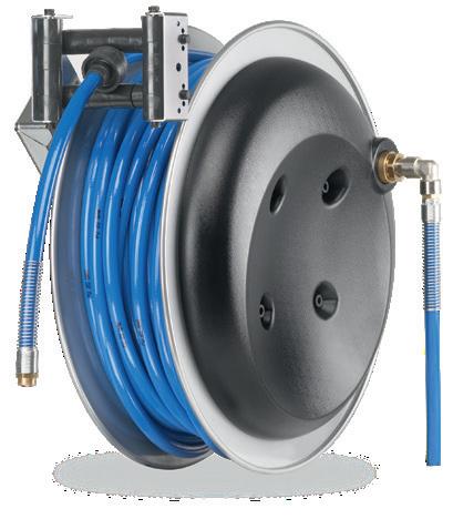
• Roller hose-guide
• Air transmission pivoting joint without slotting
• Steel springs suitable to grant the optimum hose traction and a long life
ALL THE ITEMS ARE AVAILABLE ALSO WITHOUT HOSE.
• Ausführung in heisslackiertem Aluminium und Stahl.
• Seitlicher Befestigungsflansch aus Aluminium, mit integrierter Zahnarretierung (die Zahnarretierung wird ausgeschaltet geliefert und ist von dem Benutzer leicht einzuschalten - vor Inbetriebnahme).
• Öffnung der Schlauchführung mit Rollen.
• Durchgangsgelenk für Luft ohne Stau.
• Stahlfedern, die optimalen Zug des Schlauches und eine lange Lebensdauer garantieren.
ALLE ARTIKEL SIND AUCH OHNE SCHLAUCH
■ EN Optional fastening bracket. The hose reel is standard supplied for side fastening. ■ DE Optionaler Befestigungsbügel. Die Rolle wird standardmäßig geliefert und ist für die seitliche Fixierung vorbereitet.
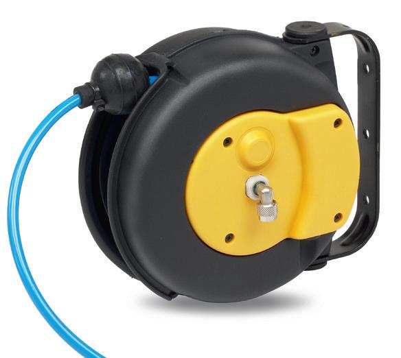
Air - Water
9100
■ EN TECHNICAL FEATURES
Mini-reel for applications in the industrial sector and for hobby.
• Monoextruded Polyurethan hose.
• Technopolymer casing.
• Provided with hose ratchet stop device, easily removable if constant traction is required.
• Working temperature: -5 °C/+40 °C.
■ DE TECHNISCHE MERKMALE
Kleiner Tischschlauchaufroller für Anwendungen in Industrie, Handwerk und Hobby.
• Blauer monoextrudierter Polyurethanschlauch.
• Struktur aus Technopolymer.
• Austrichtbarer Befestigungsbügel aus Metall.
• Automatische Vorrichtung zum Stoppen des Schlauchs auf der gewünschten Länge, evtl. trennbar.
95
8900 9100
8900 SERIES 9100 SERIES
LIEFERBAR
TECHNISCHE MERKMALE ■ EN ■ DE ART. 8911 8921 8922 8931 8932 8941 8951 Hose Int. Ø 8 mm (5/16”) 10 mm (3/8”) 10 mm (3/8”) 12,5 mm (1/2”) 12,5 mm (1/2”) 19 mm (3/4”) 25 mm (1”) Hose length 47 m 32 m 42 m 32 m 42 m 17 m 10 m Max press 20 bar 20 bar 20 bar 20 bar 20 bar 10 bar 10 bar End hose fitting 1/4” M BSP 3/8” M BSP 3/8” M BSP 1/2” M BSP 1/2” M BSP 3/4” M BSP 1” M BSP Hose type KPU PVC Hose color BLUE BLACK Temperature -5°C/+50°C -5°C/+40°C Incoming hose fitting NO Incoming hose 1 m Air YES Cold Water YES Dimensions B 160 130 160 130 160 160 C 390 360 390 360 390 390 Without hose 8911 ST 8921 ST 8922 ST 8931 ST 8932 ST 8941 ST 8951 ST dimensions 8900
■ OPTIONAL ART.
Fastening option 8900
BRACKET ART. 9100/6 Hose Int. Ø 5,5 mm Hose length 6,5 m Max press 12 bar End hose fitting 1/4” M BSP Temperature -5 °C/+40 °C Incoming hose fitting Ø 6x8 Incoming hose NO Suitable for
Hose type PU Hose color BLUE 100 1 mm 240x185x120 Kg 2 7 R 95 100 120 100 50 120 dimensions
ISO EN 12100 2006/42/EU
8901
with
1/4 ”F BRASS INSERT EINSATZ AUS MESSING 1/4 ”F
KPA055
AIR BLOW GUN DRUCKLUFT PISTOLEN
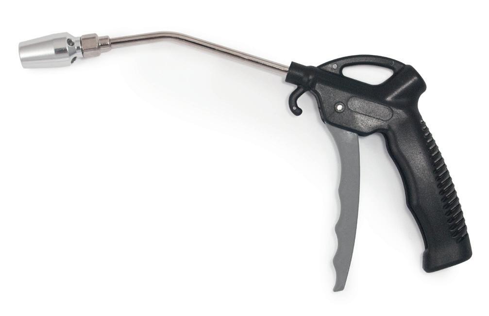
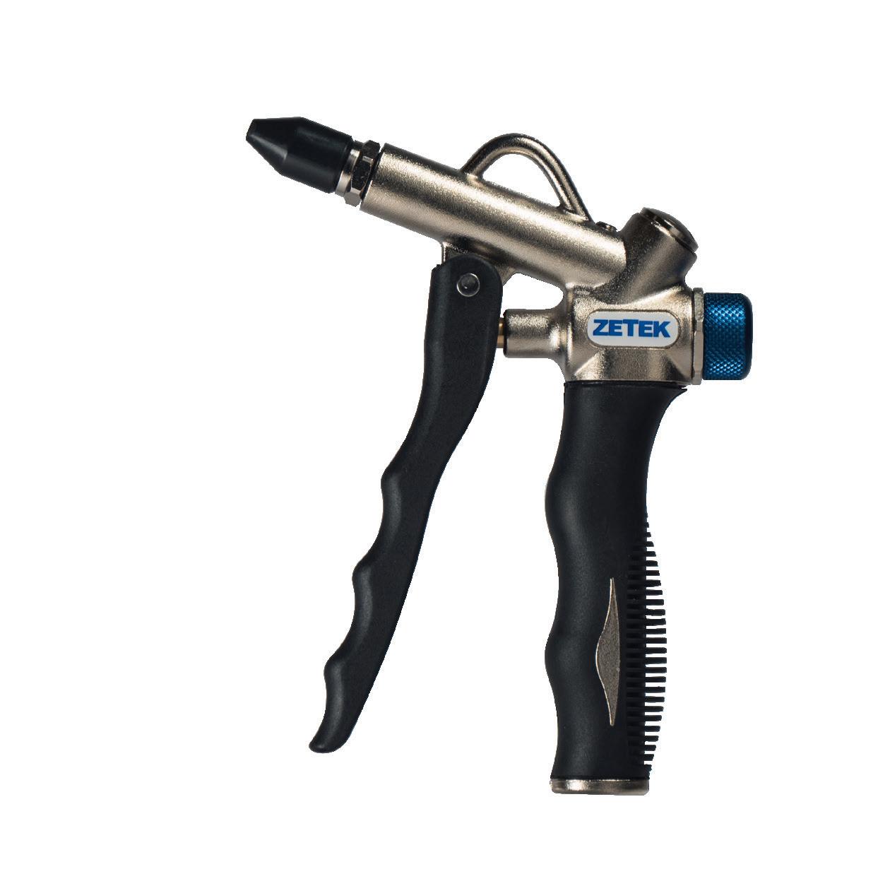
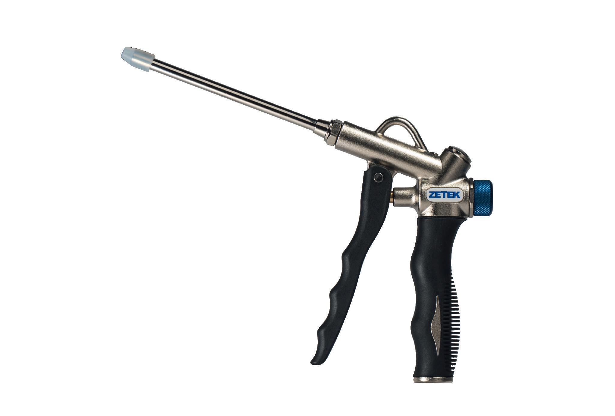
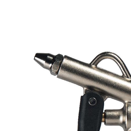
WORKING PRESSURE BETRIEBSDRUCK MAX 8 BAR
TEMPERATURE RANGE ·BETRIEBSTEMPERATUR -20° + 70°C
160mm +165% INCREASED AIR FLOW HÖHERER LUFTVOLUMENSTROM
887l/min
KPA440
FLOW REGULATION REGELUNG VOLUMENSTROM
KRATZSCHUTZ-DÜSE AUS GUMMI GERÄUSCHEMISSION
96
ERGONOMICALLY DESIGNED HANDLE WITH HANGING HOOK ERGONOMISCHER GRIFF MIT AUFHÄNGEHAKEN
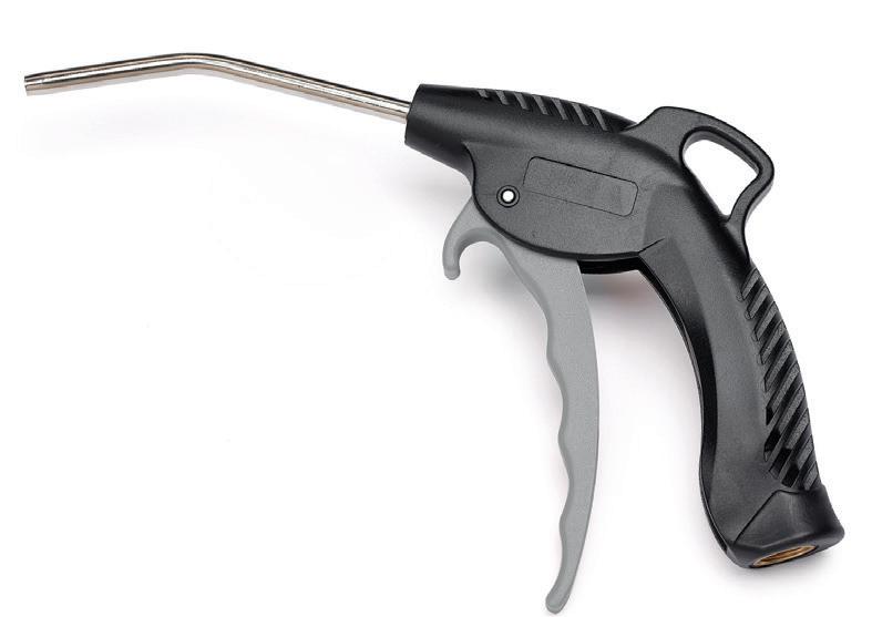
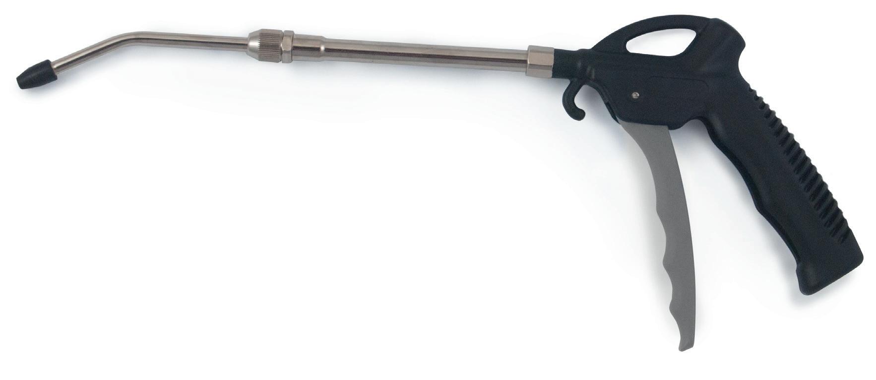
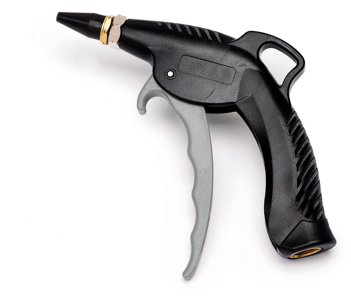
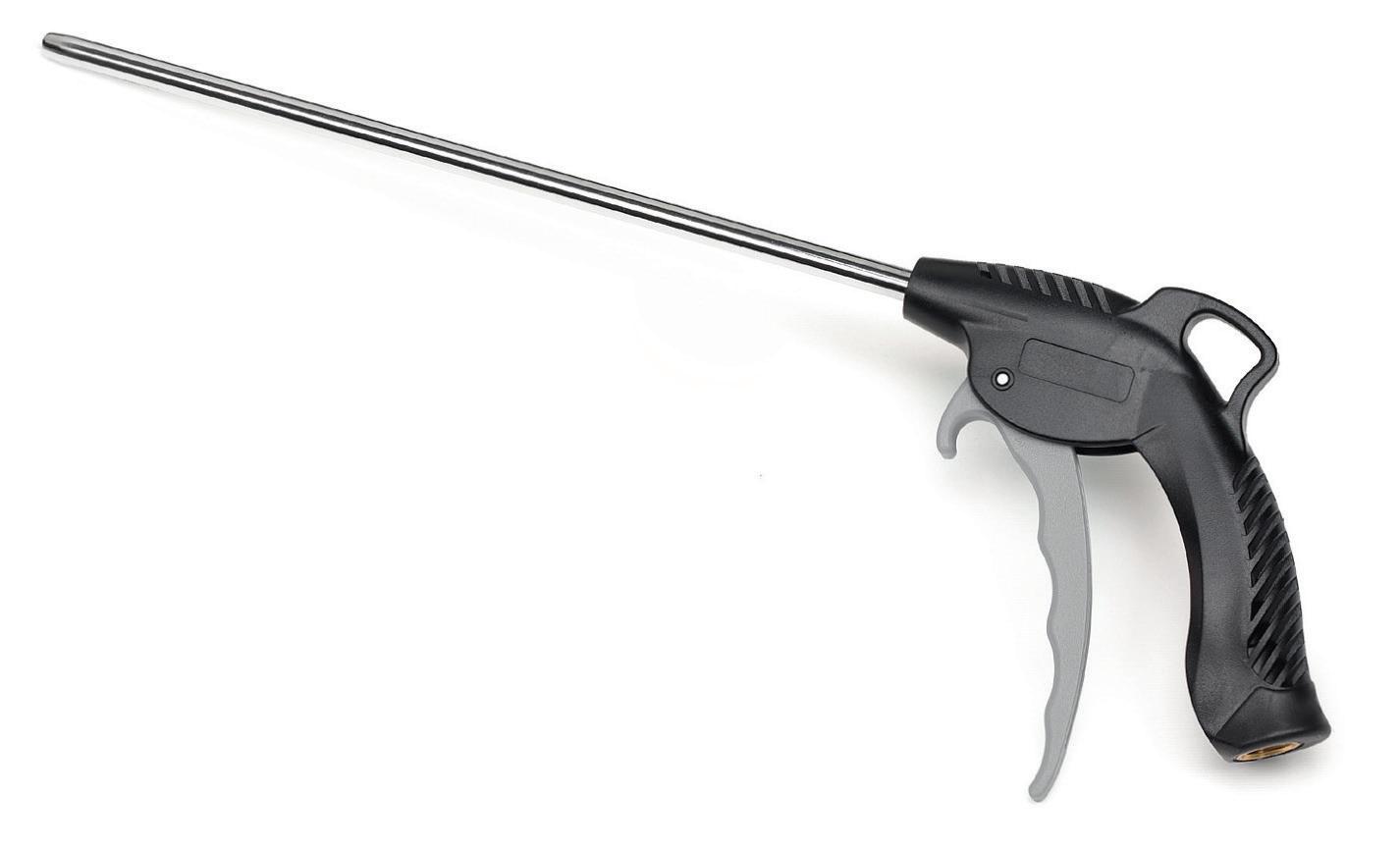
PRECISE CONTROL OF FLOW RATE PRÄZISE VOLUMENSTROMREGELUNG ZUR OPTIMIERUNG DES LUFTVERBRAUCHS

215mm / 310mm
RUBBER PROTECTION SCHUTZ AUS GUMMI
EXTENSIBLE AUSZIEHBAR KPA040/12
NON SCRATCHING RUBBER NOZZLE KRATZSCHUTZ-DÜSE AUS GUMMI
INDIVISIBILE 12 PCS DISPLAYER
INDIVISIBILE 12 PCS DISPLAYER
97
KPA015
1000mm
500mm
KPA020
KPA100
2003/10/CE 1910.95 (b)
97/23/CE 2011/65/CE ‹ 87 dBa
STEEL NOZZLE DÜSCHE AUS STAHL
KPA030/12
[OSHA]
AIR BLOW GUN DRUCKLUFT PISTOLEN
GENERAL TERMS OF SALE
Our general selling conditions, valid for all legal purposes, can be found on our website www.zeca.it
Pictures, explanations and technical details of this catalogue have only an indicative purpose. Consequently ZECA has the right to make changes, without notice, for the sake of improving the products or for any constructive or commercial requirement.
PRODUCT LIABILITY:
ZECA products are insured for “PRODUCT LIABILITY” worldwide coverage.
DIRECTIVE 2002/95/EC (1) - 27/01/2003 (ROHS): We Zeca SpA DECLARE that all our products, when affected by RoHS Directive 2011/65/UE and any further changes, meet the RoHS requirements.
WARRANTY:
· 12 months from the date of purchase, unless otherwise stated.
· The warranty of 12 months refers to defects on new products delivered by us, used in a proper way. Parts subjected to wear and tear (cables, springs, hoses, collectors, etc.) or eventually damaged by users are therefore excluded.
· Any other indemnity form remains obviously excluded.
· The warranty consists in the free of charge replacement or alternatively in the repair in our works of products subjected to malfunction caused by defective parts.
· All transport costs are at purchaser’s charge.
· The warranty will not be applied when goods have been damaged due to misuse
Our goods are packed in strong cartons. Every item has individual package ready for sales, containing directions for use, where necessary.
When effecting shipment to customers, according to order variety, each article is repacked and protected for the transport.
CAUTION: individual package is not suitable for an individual shipment. For delivery of an individual carton, it is necessary to use an additional stronger carton.
Zeca products are well known all over the world for quality and technology and strictly conforms to the rules.
Technical features are clearly shown at side of each item. Products, if required, conform to EEC rules and are regularly CE marked.
The selection of the required model should be made by customer according to the foreseen use. User has the responsability to check that the selected model is suitable for his working place.
■
ZECA achtet besonders auf eine stabile Verpackung ihrer Produkte. Jedes Produkt hat eine individuelle Verpackung für den Verkauf, in welchem die Gebrauchs- und Installationsanweisungen enthalten sind, sofern notwendig. Bei Versand werden die einzelnen Produkte je nach Auftragsart ein weiteres Mal verpackt und für den Transport geschützt.
ACHTUNG: Die Verpackung des einzelnen Produktes IST NICHT vorgesehen für Einzelversand. Im Falle von Einzelversand ist eine zusätzliche verstärkte Verpackung notwendig.
Die ZECA Produkte sind weltweit berühmt für Qualität und Technologie da sie den Normen entsprechen.
ALLGEMEINE VERKAUFSBEDINGUNGEN
UND GARANTIE:
Auf unserer Website www.zeca.it. Können Sie unsere allgemeine Verkaufsbedingungen und Garantie finden, gültig für alle rechtlichen Zwecke.
98
■ EN ■ EN ■ DE
Die technischen Daten stehen im Katalog neben dem jeweiligen Produkt. Die Produkte, entsprechen den EEC Normen und werden mit CE Markierung geliefert (sofern erforderlich). Der Kunde soll die Wahl zwischen den verschiedenen Modellen auf Grund der Verwendung vornehmen. Der Benutzer ist verantwortlich für die richtige Wahl des Gerätes für seinen Arbeitsbereich. DE
DISPLAY RACK
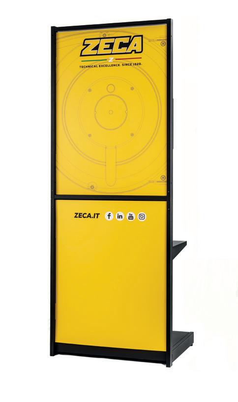
(supplied without products)
ITEM 005/06
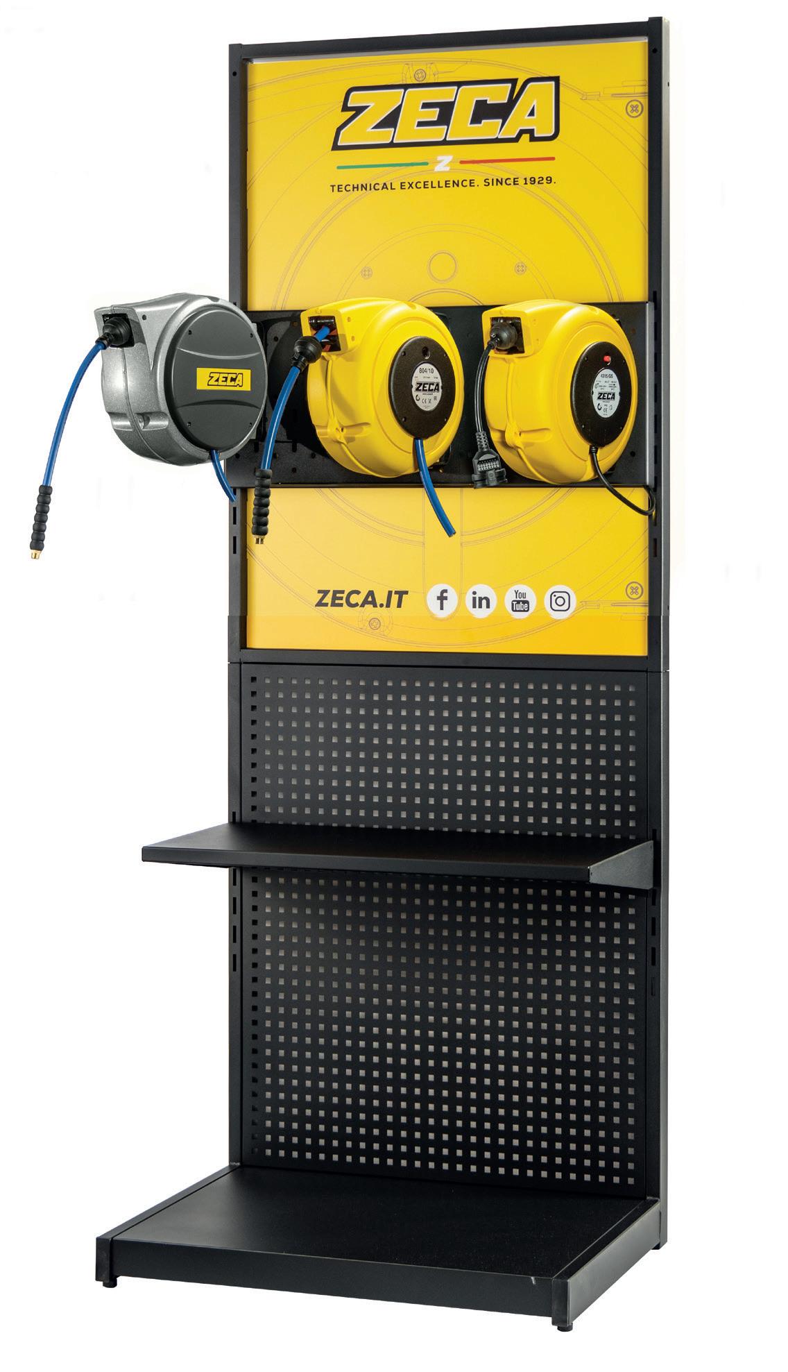
99 202 cm 77 cm 55 cm
L80 x H176 x D60
100 10,5 GF/0323/10000 010.0240 Strada della Chiara, 25 10080 Feletto Canavese (To) Italy Tel. +39 0124 499630 export@zeca.it
