
PART A:
Delft University Laboratory

New and Demountable
Building D(emountable), by Cepezed

STUDY Zachary Soong Ya Ng 20104034 CPU[ai] 2022-23 to
BUILDING CASE
1. Key Design Parameters

2. Structural Design Strategies

3. Building Fabric and Construction
Building D(emountable) is Cepezed’s prototype of office s that can be fully disassembled as per the Netherland’s legislation requiring all buildings to be fully circular by 2050. This office unit can be fully taken down to its core components and erected at a different site depending on the need.
Cepezed offices surround this prototype office as part of Cepezed’s campus of rentable office units with carparks and electrical chargers further surrounded by historic Dutch Baroque retrofitted townhouses.
The previous brownsite was a result of an obsolete Delft University laboratory and is now replaced with Building D(emountable).
Plenty of pedestrian and cyclist routes link the canal and commercial & healthcare buildings from North to South.


Evaluations
1. Sustainable Land-use and Ecology
Cepezed’s new demountable prototype prioritises building reuse for any buildings too obsolete to retrofit, and instead builds upon the existing foundation (Fig 1.10)
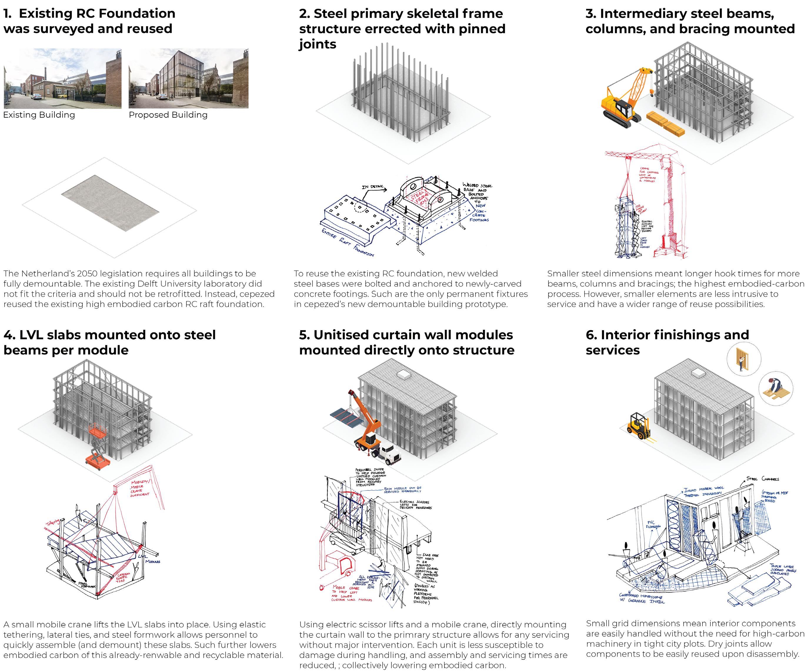

Decomissioning the old Delft University laboratory’s heavy gas and water pipes retracts the brownsite’s boundaries (Fig 1.1)
Dry joinery and locally-sourced materials reduce wastage and local pollution during diassembly and reuse phases (Fig 1.11)


2. Sustainable Connectivity and Transport
The site’s inaccessibility to car roads led Cepezed to facilitate cyclists and pedestrians links adjacent to their offices (Fig 1.1)
Carparks around Cepezed’s offices are fitted with electric vehicle chargers as all Dutch cars are to be fully electric by 2030 (Fig 1.1) Such carparks are shared by multiple offices, promoting car sharing amongst office workers with similar commutes (Fig 1.1)
3. Sustainable Communities and Social Value
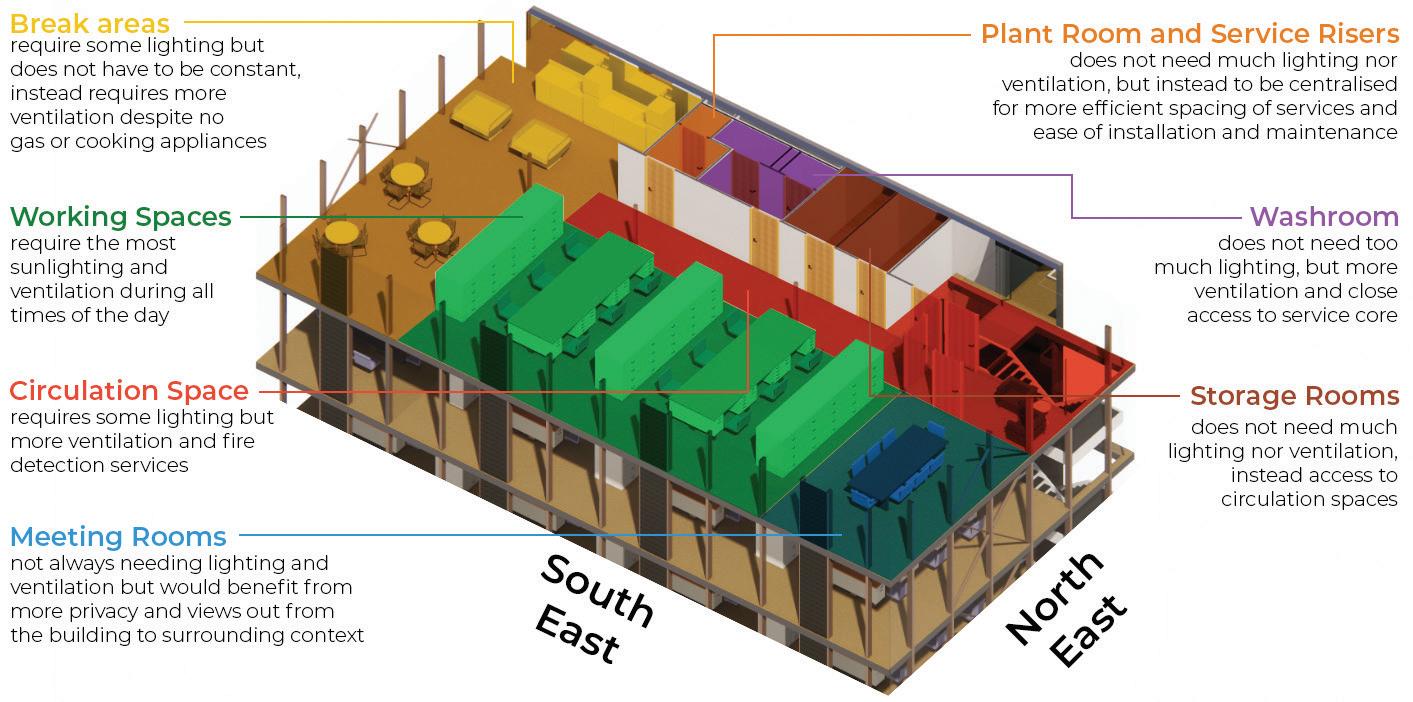
Different firms can occupy different floors, while able to arrange hotdesks and meeting rooms according to their needs (Fig 1.7) Curtain wall improves user wellbeing and promotes views facing older Dutch Baroque buildings despite being a new modern office prototype (Fig 1.1)


Internal spaces are kept open and clearly divided between work, ancillary and circulation space; allowing users to get a clear understanding of the space and the fastest way to evacuate the building (Fig 1.7)


A large number of steel structural members have smaller dimensions between to emphasise the lightweight structure with shorter spans, while benefitting from economies of scale during assembly and disassembly.

Only the service core and lift shaft have interior walls; neither interior nor exterior curtain walls are load-bearing.

Curtain walls provide unobstructued daylighting along 3 of 4 faces into main working spaces.
Passive ventilation brings in fresh air using operable ventilation flaps, while active ventilation extracts any stale air through the HVAC systems core.
Each floor contains any fire within, preventing any spread thanks to proper treatment to regulation, while smoke is exhausted through the ventilation flaps.
BA3 Technologies Part A: Building Case Study (BCS) - Sheet 1: Construction, Materials, Structure Building D(emountable), Cepezed, Delft Zachary Soong Yan Ng - 20104034 CPU[ai]
Fig 1.1: Location & Site
Fig 1.2: Climatic Context
Fig 1.3: Isometric Structure Buildup
Fig 1.10: Elemental Build-ups and Zone Details
Fig 1.11: Elemental Build-ups and Zone Details
Fig 1.7: Key Plan and South East Elevation
Fig 1.8: Ventilation
Fig 1.9: Fire Strategies
Fig 1.4: Short Section Load Paths
Fig 1.5: Long Section Load Paths
Ecological & Environmental Evaluation
Fig 1.6: CLT Module and Loads
Description & Analysis
BA3 Technologies Part A: Building Case Study (BCS) - Sheet 2: Energy and Environment
2. Environmental Design Strategies
3. Interior Environment Analysis
Maintaining a cubic form allows maximum use of space in an already-tight city plot. This also allows each building face to recieve the maximum amount of direct sunlight with a singular flat surface no matter the sun path or azimuth.
Summer and winter winds incident on these straight faces are not always funneled into interior spaces effectively, but are mitigated enough without the need from any additions to the building form.
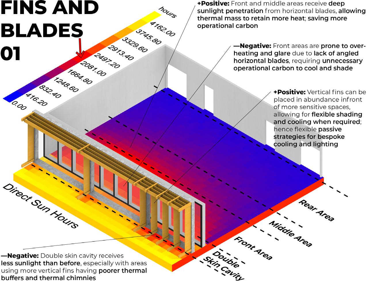
A lack of brise soleli and only implementing roller blinds means the passive daylighting strategies combatting glare and overheating are rather poor. However, this can be justified for two reasons:
The prototype is meant to be moved to different sites, and as such, cannot rely on one iteration of solar shading (but should include a modular or rearrangable shading system)
• The programme itself does not extend past evening hours, and does not need thermal comfort at night; hence only temporarily mitigating glare and overheating is just enough for the bare thermal and lighting comforts
Evaluations
1. Sustainable Water Cycle
Siphonage drainage system spaced out over the flat roof is a lowflow fitting using only one leading pipe culminating into the small service riser (Fig 2.5)
Since each floor is its own fire compartment, no sprinklers are required but only require fire detectors and alarms. Additionally, using an ASHP consumes less operational carbon than water-based radiators (Fig 2.6, 2.7)
Curtain wall is self-cleaning with rain runoff and maintains an airtight seal between each unit. Any leaks are easily detectable and can be serviced without intervention into walls or slabs
2. Good Health and Wellbeing
Individual vent flaps can be locally-operated per bay of tables depending if a bigger intake of fresh air is required. Lighting sensors are spaced out per bay of tables to save energy while providing ample lighting during limited occupancy (Fig 2.10, 2.11)

Floor-to-ceiling curtain walls come equipped with blinds to mitigate any glare and excessive thermal gains during all times of the year and any extremeties in sunlight levels (Fig 2.9, 2.15)
Hot & cold air vents and ventilation flaps align with each bay of tables, and can be controlled depending on each user’s individual thermal comfort (Fig 2.11, 2.12)


3. Net Zero Operational Carbon
Curtain walls prioritise efficient U-values using thick glass panels, meaning thermal strategies adopt a fabric first approach
This could be improved with new brise soleli and light shelves (Fig 2.10, 2.13)
ASHP does not need to be on maximum capacity thanks to passive heating and cooling strategies, instead only to be used after hours or during limited occupancy (Fig 2.12, 2.14)
With mechanical and electrical appliances alligned per bay of tables using light sensors and ventilation controls, appliances use low energy and prevents overheating and overlighting the entire floor space (Fig 2.6)
Plants rooms and service risers are aligned with the NW building face, which recieve the least sunlight. Such does not decrease useful and marktable office space.
HVAC and ASHP originate from a central point in the floor plan, distributing vents and ductworks in the most efficient layout with least interventions into floor slabs and steel construction.

Lift Services positioned next to the plant rooms and service risers help mitigate noise pollution and vibrations coming from a single origin, opposed to opposite ends of a floor plan.

Lighting Strips and motion sensors activate based on which bay of workstations are occupied. This saves operational carbon during limited occupancy.
Electrical casings and fire devices use ceiling wires running along the underside of exposed CLT slab. This allows for accessible servicing without compromising the entire system, opposed to underfloor wires.
Electrical mains from site come from under-foundation HV cables penetrating slabs at one spot. Alternatively, HV cables could enter from the side through walls, but would require an additional service core protruding onto the street.
Boiler rooms and any vibrating pipes are positioned furthest away from important working and meeting spaces. Such distancing most effectively reduces noise pollution.
Water pipes only travel as far to adjacent rooms to the service risers, thereby reducing the intervention into suspended ceilings and walls in the most efficient centralised layout.
Rainwater pipes may be distanced quite far from each other, but use a siphonage drainage system using less drain inlets. This allows the roof to adopt a clean and short parapet.
Despite closing blinds during the day, the diffused sunlight is ample enough for workplaces without any glare
Solid core wall restricts unwanted evening glare and heat Lacks any brise soleli to fully benefit from the floor-to-ceiling curtain wall
Floor-to-ceiling curtain wall on 3 out of 4 walls maximises solar penetration to all workstations during all daylight hours Active lighting strips align each bay of workstations, and can be manually activated depending on occupancy rates Lacks light shelves to still capture sunlight during gloomy days
Fig 2.12: Summer Cooling (Night)
Operable ventilation flaps allow summer winds to cross ventilate workstations and meeting rooms
Roller blinds help manually shade and reduce solar heat gains ASHP can provide additional cooling on less-windy days or when temperatures fluctuate too high
Night flushing ventilation per storey using vent flaps on three adjacent building faces; cross ventilation per storey Thermal mass is cooled as a result and ready for the next day No active cooling systems required from ASHP as building is not occupied past evening hours
Full use of ASHP, but Heat Recovery systems and manual controls per storey help save on operational carbon HVAC systems work more efficiently with more users present as humidity increases and radiant body heat is more apparent Solid core wall blocks any West and North-West frigid air drafts Some heating from limited winter sunlight incident on CLT slab


Thermal inertia of CLT slab may not be as efficient as masonry, but is sufficient enough to radiate heat for limited occupancy ASHP and Heat recovery run on lower capacity per bay of desks Heat from the day is retained as long as vent flaps are sealed shut, with any air circulation done mechanically
• Blinds help to mitigate any glare while still diffusing enough sunlight onto workdesks


A lack of reflective materials shows how poorly lit the further one moves away from the curtain walls, especially during early hours
Blinds are only employed to mitigate morning sunlight glare, but are rolled up for ample direct lighting throughout the office
• Workstations recieve constant diffused light no matter how deep into the floor plan
Blinds are also only used to block deep morning glare onto workstations, but are rolled up for the rest of the day and allow soft lighting in, though inconsistent
• Workstations cannot rely on enough sunlighting, and must use active lighting
1 2 B A C D E F G H 3 4 5 6 7 8 9 10 11 12 13 14 10 Electrical Channels with plug sockets Smoke Detectors WiFi Router Electrical Switch Electrical Looping Lines Motion Detectors Fresh Inlet Vents Stale Outlet Vents Air Handling Units Strip Lighting Pendant Lighting Lift Car guides Counter Weight guides Boiler Unit Hot Water pipes Cold Water pipes Foul Water pipes
Building D(emountable),
Zachary Soong Yan Ng - 20104034 CPU[ai]
1. Theory & Strategy
Cepezed, Delft
Fig 2.1: Overall Massing and Form
Fig 2.2: Interior Arrangement
Fig 2.3: Mechanical Systems Fig 2.4: Electrical Systems Fig 2.5: Plumbing & Drainage Systems
1PM 1PM 1PM 6PM 6PM 4:30PM 9AM 9AM 9AM
Fig 2.6: First Floor Reflected Ceiling Plan Fig 2.7: First Floor Short Section of Service Systems
Fig 2.9: Summer Lighting
Fig 2.11: Summer Cooling (Day)
Fig 2.13: Winter Heating (Day)
Fig 2.14: Winter Heating (Night)
Fig 2.15: Office Workstations during Summer Solstice
Fig 2.16: Office Workstations during Equinox
Fig 2.17: Office Workstations during Winter Solstice
Fig 2.10: Winter Lighting
Fig 2.8: Certified and regulated spacing between service components
Ecological & Environmental Evaluation Description & Analysis
Compliant with Regulation 6 of Workplace Health and Safety, HSE Compliant with Category L2 (from 1-5) Early Fire Detection system, ARUP Compliant with Regulation L2 Commercial of Lighting, Approved Doc L Service riser & void Steel Channel Support G H F E D C B A Pendant lights Strip lights Electrical channels Plug sockets Circuit Breaker Foul water pipes Outlet vents Inlet vents Hot water pipes Cold water pipes Vent spacing: Lighting Sensor spacing: Smoke Detector spacing: Compliant with Regulation 6 of Workplace Health and Safety, HSE Compliant with Category L2 (from 1-5) Early Fire Detection system, ARUP Compliant with Regulation L2 Commercial of Lighting, Approved Doc L
Vent spacing: Lighting Sensor spacing: Smoke Detector spacing:
1. Synthesis & Argument
Detailed Assembly / Building Fabric
• Minimal use of high-embodied carbon steel elements: By fixing steel angle brackets directly onto the primary structure steel z-beam, this reduces the need for a separate secondary structure to hold the curtain wall; further emphasising the ease of disassembling these robust materials in a lightweight structure. (Fig 3.10, 3.11)


Dry joinery using bolts and screws: Fixing any steel and aluminium elements together exclusively use nylon and steel bolts and screws. This further emphasises the minimal wastage of resources upon both assembly and disassembly, without requiring any welding guns (higher embodied carbon processes); pushing for cradle-to-cradle design. (Fig 3.2 - 3.9)
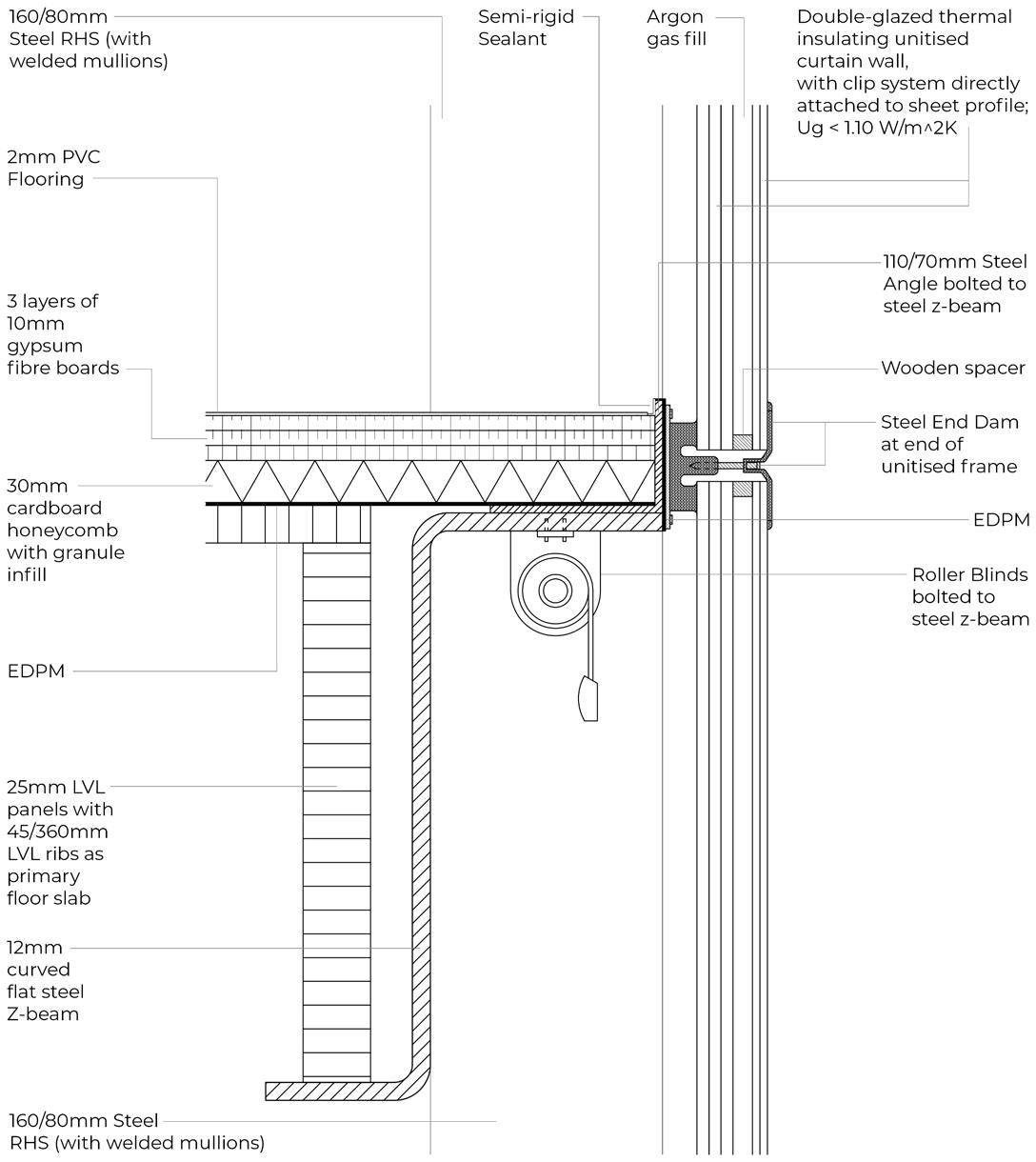

• Continuous layers of insulation and membranes: Thanks to the already-minimal wall and floor build-ups, more insulation could be justified between joints of curtain walls, roof parapets, and slabs. Such minimises cold bridging often found between joints, thereby further reducing operational carbon. (Fig 3.1)


Change Over Time
Longevity of service components and appliances: Without the use of permanent gas fixtures nor any welding of piping and drainage, each component can be disassembled to its original prefabricated specifications. Such allows for flexible reuse, not only in the same building erected elsewhere, but also other constructions. (Fig 3.1)
• Weather resilience and hardiness during transport and assembly processes: of any steel, aluminium and SIP elements may have higher embodied-carbon, but are planned to be used for the long-term well after Netherland’s 2050 legislation. With these key structural components having long lifespans, other parts of the buildup are more frequently replaced and assembled according to this demountable lightweight structural model; high-carbon cost that pays off more and more in the long run. (Fig 3.1)
• Wide range of reuse and adaptation possibilities: thanks to smaller steel dimensions and modular units of unitised curtain walls and CLT floor & roof slabs. This demountable office prototype can be errected on other sites with different foundation sizes, even in tight city plots with limited working space. Paired with the close coordiation of all MnE, CnS and contractor teams, all prefabricated elements can be erected quickly and with longterm sustainable life cycles.
(Fig 3.1, 3.12,
Evaluations
1. Net Zero Embodied Carbon
Dry joints and a lightweight construction buildup for each layer allows the building to fully disassemble back to its core manufactured parts Little to no resources are wasted when removing joinery, while each component’s embodied carbon carries on to the next application (Fig 3.1 - 3.9)
Each component may be made from high-embodied carbon materials, but are designed for longer lifespans to facilitate more reuse options over longer periods of time Any other prototypes, whether by Cepezed or other firms, adopting this demountable concept essentially create an open-sourced network of reusing and recycling each component a vision soon to materialise in 2050 and beyond. (Fig 3.1, 3.10 - 3.14)
Consider modular off-site construction systems - Main building elements (steel z-beams, RHS columns, unitised curtain walls) are modular and prefabricated by Dutch specialists offsite and assembled on site with specific screws and bolts shared between each manufacturer. This reduces assembly (and dissasembly) times, transportation times, and any high-embodied carbon processes (such as hook times on cranes); bringing down embodied carbon as a whole. (Fig 3.1 - 3.9)

2. Sustainable Life Cycle Cost
Embodied carbon is decreased by installing fewer system components thanks to effective and regulated spacing. Paired with dry joinery and the ability to reuse each component in different arrangements for other buildings there is no disposal phase at the end of each component’s life cycle (Fig 3.1, 3.10 - 3.14)
Control panels in each enclosed room measure energy costs and hel regulate the operating capacity of ASHP heating and cooling systems. As with lighting systems and sensors, the occupancy rate and the priority of use between each workspace and meeting room help to balance the operational carbon (Fig 3.1) Since all building components are prefabricated and categorised per RIBA stage of work, any maintenance required can be easily coordinated with the responsible contractor or engineer Building components are already left exposed in this lightweight structure, and any intervention into other building systems is minimal. Should the need arise, prior coordination between both parties set a precedence for the least intrusive method of servicing a particular component. (Fig 3.1, 3.10-3.14)
2. Integrated 3D Envelope Study
Steel RHS columns and Z-profile ring beams are fixed with Steel M20 bolts using easily-handled equipment
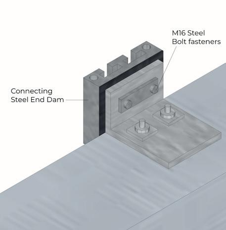
Curtain wall’s connecting brackets slide into end dams with low tolerances, and are then fixed in place with bolt anchors.
3. Junction Details
Steel angle brackets are fixed to the Z-beam with underfloor bolt anchors.


Openings for these bolts are prefabricated.
Rubber isolaters and connecting steel plates use screws to fix themselves onto each curtain wall module.
EPDM sealant uses a glue adhesive to attach itself to steel faces. An alternative would be screws in a thicker sealant.
Fixing bracket are latched onto bolt anchors, without the need for any welding like stick curtain wall systems.
Connecting end dams are fixed with bolt fasteners, and can be reused with other steel connection joints.
Lastly, cover caps are placed over all pressure plates with a latch and screw system to the manufacturer’s detail.
Building D(emountable), Cepezed, Delft Zachary Soong Yan Ng - 20104034 CPU[ai]
Ecological & Environmental Evaluation Description & Analysis BA3 Technologies Part A: Building Case Study (BCS) - Sheet 3: Detailed Envelope Study
3.13)
Fig 3.1: Isometric 3D Envelope
Fig 3.2: Steel Structural Connections
Fig 3.6: Connecting Brackets
Fig 3.3: Steel Angle Brackets Fig 3.4: EPDM Sealant Fig 3.7: Connecting Plates between Fig 3.8: Fixing Brackets above Fig 3.9: Cover caps
Fig 3.5: Connecting End Dams
Fig 3.10: Corrugated Wall to Floor Slab
Fig 3.12: Corrugated Wall to Ground Foundation
Fig 3.14: Ventilation Flaps Head & Sill
Fig 3.11: Curtain Wall to Floor Slab
Fig 3.13: Curtain Wall to Ground Foundation
Lecture Commentary Series
PART B:
1. Retrofit First
2. Timber Construction
3. Advanced Facades
4. 5 Plus Architects
Zachary Soong Ya Ng 20104034 CPU[ai] 2022-23
5. IDEAhaus
BA3 Technologies Part B: Technological Discourse - Lecture Commentary Series
1. Retrofit First 2. Timber Construction
Date: 30th January 2023
Speaker: Glenn Ombler
Position: Principal Architect
Organisation: Ombler Iwanowski Architects
3. Advanced Facades 4. 5 Plus Architects 5. IDEAhaus
Date: 6th February 2023
Speaker: Kevin P. Flanagan
Position: FRAIC
Organisation: Royal Architectural Institute of Canada
Date: 13th February 2023
Speaker: Rhodri Evans
Position: Facade Engineer
Organisation: BDA Facade Consultants

Date: 6th March 2023
Speaker: Laura Stafford
Position: Architect Associate
Organisation: 5plus Architects
Date: 13th March 2023
Speaker: Ian McHugh
Position: Architect
Organisation: Green Triangle Studio
Design Methodology & Technological Strategy
When it came to retrofitting the Zenith Office Building in Manchester, two strategies were employed: reconfiguring the interior spaces and improving the envelope and environmental control strategies.


Firstly, spatial reconfiguration of this old Royal Mail office building comprises of removing ‘soft spaces’ and unnecessary filler and non-loadbearing walls, columns and beams. This also primarily helps to appease the new proposal’s building regulations.
The new client, Zenith, was looking to build a speculative office building where office units are built for general needs as users are not finalised in a contract. As such, there are no end-users at the time of the design and handover stages. Instead, the brief was to expand each floor plan with more useful space to rent out, while splitting potential occupants for more firms per storey. Secondly, altering the envelope and environmental control systems looks to incorporate more advanced green technology and self-sufficient energy sources, as well as recycling and reuse opportunities. This plays to the bigger picture of decarbonising the energy grid from the built sector.
These strategies were also adopted by the MMU Estates Development team when repurposing and retrofitting an older building present on my 3.1 site. While not as old as the Royal Mail office, the existing building was a car showroom and repair horse tailored to a very specific programme. With MMU now occupying the plot, they decided to split up interior spaces for more office workstations, but kept the workshop and instead refitted it with more advanced environmental control systems and green technology. This is an example of being able to balance the needs of new MMU programmes without constructing a new building with a significantly higher carbon footprint than a retrofit option.
Responsibilities
The architect’s primary responsibility when retrofitting an older building is balancing the client’s demands with safely expanding and changing the building structure. With the looming alternative of constructing an entirely new building with much fewer restraints than retrofitting an older building, consulting with surveyors and engineers to tone down plans appropriately is key to communicate with the client. The Zenith Office Building’s existing RC structure did not have enough capacity for three new storeys, so engineers compromised on a steel frame structure superposed above the original building for three additional floors. Such floors were turned into a penthouse office unit as the main selling point for this new proposal.
This poses another professional and statutory responsibility the architect must juggle with the client’s demands. The Zenith client was concerned with profitability and presenting a modern image of their new office building, while architects have learnt to respect the UK’s built heritage. As older buildings lack intrinsic value compared to new and upcoming projects, architects must balance these commercial priorities of their clients by justifying the historic status of an existing building. Of course, this is much easier when said building is a listed and conversed heritage site. However, this failed to garner the interest of my CPU[ai] peers to retrofit the older car showroom, instead fancying their taller and flashier proposals built from the ground up that has become synonymous with our atelier. I too am no exception.
Compliance
External compliance still played a role in balancing the client’s priority of profitability and preserving heritage. Historic England made sure that office blocks in the city centre maintain a degree of pedigree synonymous with Manchester’s Victorian image. The British Council for Offices (BCO) set criteria of contemporary use, spatial standards and climate concerns that must still be met, whether an office is retrofitted or built from the ground up.
This impacts any risk factors of potential redevelopment and profitability after the client’s initial plans and demands are amended without their say. In a contract, this impacts the rental rates based on Grade A*** standard units (which are easier to build than to retrofit), any floor yield / plot ratios dependent on planning permission, and subsequently any projected rental (especially when business models assume a fixed occupancy rate). Such uncertainties in these following factors now amended, whether directly or indirectly, begin to sway developers towards new builds over retrofitting options.
Design Methodology & Technological Strategy
PLP Architecture’s new state-of-the-art office building ‘The Edge’ in the Netherlands employs two design methods when working with timber: The strengths and carbon offset capabilities of LVL & CLT materials and Celebrating the natural finish of composite wooden construction with massive open forms
To create massive forms and open expanses within, the height of the building scheme was best solved with CLT and LVL primary structure and floor build-ups. With a lower embodied carbon than conventional building solutions, as well as maintenance and servicing systems already beginning to incorporate timber builds, this decreases operational carbon as no new services are required (something MMU Estates is currently lacking for those looking to build with CLT in 3.1). Although fire zonage is much more strict and limiting, fire compartments per storey are smaller and more frequent (hence smaller interior spaces), but The Edge structures a programme that benefits from these interior divisions. By designing working spaces not as small individual seating nor as large collaborative spaces, adopting a hotdesking approach is most beneficial for these space constraints.
Aside from the medium-sized spaces, there are massive atriums as focal points with advanced environmental systems to complement the aesthetic and improved psychological effects of exposed wood. Adopting an ‘open hand building shape’ oriented to benefit the most from gentle North diffused sunlight creates a sense of awe and empathy by changing public perception to accept this space as a green space. Playing to economies of scale with an ‘airframe’ structure to build tall and large timber structures, this version of bio-architecture is often used to clash with more fossil-fuel-economy buildings.
Responsibilities
The architect’s responsibility lies in combatting predominant conventional fossil-economy construction options with more infant bio-architecture building solutions. Public, institutional, educational and industrial perceptions go against the use of timber and LVL options. With bias leaning towards concrete and steel industries, and even plastic and polymer options as well, Kevin emphasises how the American and Canadian architecture markets a narrative to protect their domestic concrete and steel industries. Hence, the reluctance to shift industrial and production practices on these new timber trends dominated by European and Scandinavian markets.
This is why Kevin admires how ‘The Edge’ sets a precedent of incorporating new technological advancement systems into the flexible construction of timber structures over masonry and metal structures. Another perspective would be how skyscrapers are cladded with enormous amounts of high-embodied carbon glass panels supported by another high-embodied carbon structure made of steel. By using timber structural members, it becomes the choice of a lesser of two evils (assuming timber elements spanning such high heights and long spans still require steel fixtures and plates).
Compliance
Compliance comes primarily from two parties: Habitat 3.0 mandated by Natural England, and the American Institute of Architects (AIA) Trust’s ‘Alliance to Save Energy’ working in tandem with the Climate Change Conference (COP) 26. Firstly, Habitat 3.0’s biodiversity metric encourages users to create and enhance spaces with natural habitats incorporating greenery. The irony of hosting green spaces beside steel frames is why Habitat 3.0 asks for natural material finishes that improve health, well-being and welfare. Additionally, this pushes architects to design micro to macro scale biophilic designs and net-zero life cycles; CPU[ai]’s main focus.
Secondly, AIA Trust’s ‘Alliance to Save Energy’ pushes to decrease the 50% of global CO2 contributions by focusing on the carbon footprint of contractor practices and material manufacturers. This requires the complete effort of all practices to adopt safer and more ecological practices as a collective whole; still far off from the pledged goals by 2100.
Design Methodology & Technological Strategy
The Manchester Engineering Campus Development (MECD) building employs prefabricated unitised panels of curtain walls, glazing, mullions and transoms; all of which are assembled to secondary structure frames in a controlled factory environment. Only then are they erected directly onto the site’s primary structure, requiring only a crane with little hook time and minimal human intervention. Despite being more expensive to manufacture than conventional stick curtain walling systems, unitised systems instead have reduced assembly times, ease of installation and equipment, and quicker handover to the client. My Building Case Study; a four-storey lightweight steel framed office with a unitised curtain wall specialising in low tolerances. The curtain wall remains laterally-stable despite strong shear moments on its joints. A specialist steel technician was brought in to establish very limited tolerances between each curtain wall module by liaising early in the project with curtain wall manufacturers and the main contractor.
Additionally, the MECD building tested each curtain wall model with Performance Mockups (PMUs) to ensure all tolerances between mullions, transoms and edge connections are adequate in the site’s strong winds and constant rainfall. As dynamic air and water penetration tests were conducted on a PMU of the unitised curtain wall, hairline fractures appeared across transoms. Such concluded the need for thicker pressure-equalised aluminium profiles to prevent any water from entering the joints. My BCS also simulated air infiltration, dynamic and static water penetration tests, as well as structural load tests. Using PMUs show foresight in the actual practical performance of a building in the long run, potentially saving costs in damages that would have proved detrimental to actual building handover and occupation.
Responsibilities
However, despite the long-term benefits, there are high costs and proper infrastructural barriers to entry when choosing to employ unitised curtain walls and PMUs. A long rigorous process occurs between architects, MnE, CnS and MC parties when prototyping with PMUs and signing off the correct shop drawings from each party involved. This means Professional Indemnity (PI) insurance can quickly delve into a dog-eat-dog scenario. Another possibility would be how the manufacturer’s Environmental Product Declarations (EPDs) become swayed, thanks to the prototype’s data results, and market and overcharge for a ‘deep green’ product.
On the other hand, unitised curtain walls are forced to be recycled as a whole unit. Breaking down a module into its component parts is not as carbon-friendly as completely reusing each module. This poses the challenge of designing modules that can be easily adapted to different construction projects; a challenging feat as each construction will have different dimensions (sans mass-produced prefabricated structures). Any PMUs are often only used for specific testing phases, and ensuring a holistic sustainable carbon life cycle analysis would mean recycling components into the main assembly line. These concerns are reflected in my BCS as the building concept revolves around being able to completely disassemble the entire structure. All components, especially the unitised curtain wall, can be erected again at different sites as part of different office buildings depending on demand.
Compliance
Other than the previously-mentioned PI insurances and EPDs having their own regulations for proper legal liability cases, another stage of construction was talked about. During actual construction stages, the worker’s safety and efficiency were brought into question when having to assemble larger modules (over smaller components) in shorter timeframes. To keep the construction benefits of unitised curtain walls, BDA Facade consultants regulated the use of stillages with Health and Safety Executive (HSE) Construction regulations 2015 and Building Regulations 7 Materials and Workmanship. Employing wide-scale shark at higher storeys was certified by the Building Safety Act 2022 and Construction (Design and Management) (CDM) Regulations 2015.
Design Methodology & Technological Strategy
5plus Architects presents three case studies each specialising in natural, mixed and mechanical ventilation, all of which complement CPU[ai]’s position of biophilic design. With ventilation centralised in an atrium, greenery can be introduced to these high-circulation spaces to further improve thermal comfort and air quality.
As each of the three case studies maximises the site, atriums divide the deep floor plans into smaller zones with more manageable environmental conditions. I found The Hive’s use of natural ventilation most effective given how a void suspended across all floors will continuously push stale air upwards; consistent passive stack ventilation. On the other hand, the First Choice Homes office in Oldham mitigates the effects of poor air quality outside with an airtight interior plus an atrium in the middle. However, using mechanical air conditioning means the entire space—including the void of the atrium itself—is always trying to maintain the same temperature. This may not be desired as the office is not always fully occupied, as the company dedicates this building as more of a meeting space instead of a dedicated office workplace.

Responsibilities
Throughout the three case studies, 5plus Architects sets the goal of achieving net zero carbon. Their office typologies specialise in wide-scale ventilation strategies and atriums to minimise operational carbon. These strategies are marketed to clients as part of a net-zero office scheme improving workplace well-being and occupancy comfort, all the while enforcing the sustainability side of their client’s branding.
However, the architects, developers and clients are led to compromise once cost is addressed or when the concept of a net-zero office is not as relevant to the client’s other ‘carbon offsetting’ campaigns. The client’s business model may also discourage wide-scale ventilation strategies and atriums across the entire building. Should the client’s financial forecast prioritise renting out individual offices per storey to different occupiers—instead of a single firm renting the entire building—each floor requires its own individual ventilation. Such isolated strategies mean higher operational carbon compared to an entire-building approach best specialised by 5plus Architects. This would downplay their goals of net zero carbon and degrade their standards of sustainable environmental practices. However, architects are ultimately responsible to facilitate a legal agreement that most benefit the client within their cost constraints. This inability to lower operational carbon through their specialised ventilation and atrium strategies is also prevalent in my own Studio. My scheme pushes for similar office typologies for the same reasons, but may not be favoured by my theorised MMU Faculty of Health client who is concerned with the flexibility of renting out parts of the building to non-MMU occupiers.
Compliance
Designing and constructing the most appropriate type of ventilation in atriums for offices were regulated with the BREEAM certification and BCO guide, respectively. 5plus Architects design passive or mechanical ventilation aligned with BREEAM’s ‘Indoor Air Quality Credits’, paying attention to reducing indoor air pollutants and spacing ventilation pathways per specific distances between. Architects and MnE engineers were liaising early on during procurement and project management stages, as the BCO’s ‘BIM Research & Policy’ mandates a knowledge-driven and de-risked construction process. This meant both parties could agree on bespoke ventilation strategies early in the design process. Hence, the client’s overall costs were reduced; a significant problem previously discussed.
The approval process was more attuned to LETI and UKGBC consultations. All three case studies’ annual operational carbon is measured and independently verified as per LETI’s ‘Net Zero 1-Pager’. On the other hand, UKGBC’s ‘Net Zero Carbon – Operational Energy (1.2) Module B6’ regulates each office to reduce inhouse energy demand and prioritise on-site renewables.
Design Methodology & Technological Strategy
The current UK housing scene, in both commissioned developments and the housing designs themselves, is not designed for climate change. Industrialisation itself within the housing assembly process is still underemployed and could benefit from greater economies of scale. IDEAhaus looks to conceptualise both: Mitigating climate change and Adapting to climate change.
With the gradual increase of temperatures constantly fluctuating any pre-existing metric such as Passivehaus and other temperature-reliant frameworks, architecture is poised with either regulating how much it contributes to greenhouse gas emissions (mitigating climate change) or directly altering technologies and construction designs to best work in tandem with the eventual rise of temperatures (adapting to climate change). IDEAhaus pushes for passive cooling principles focused on solar shading, insulation fabric first approach, and internal gains while being able to dissipate heat from night ventilation and ground cooling strategies. Such is to take shape in mass-produced flexibly-arranged passive housing designs, that are climate resilient and industrialised to benefit most from existing UK industry practices to produce on a mass scale.
Responsibilities
Architects must be able to balance bespoke, traditional and vernacular craftsmanship with mass-produced industrialised construction techniques that are often much cheaper and more efficient to construct. Such was the same responsibility of architects swaying over towards brutalism to best meet the population’s demands during post-war austerity. Regardless of which option is chosen, both sides must deliver on constrained timeframes and consistent manufacturing quality.
Although industrial construction techniques are inherently more reliant on predictable cost & delivery while benefitting from economies of scale, more vernacular methods would then be drafted out unless designers look for something bespoke and an independent idea. These benefits of vernacular craftsmanship do not best transfer over to the current housing crisis and need for as many houses in as little time as possible. Instead, the proposed IDEAhaus notions of spacious and individualised spaces boil down to interior finishings built upon a strong backbone of efficient thermal, lighting and ventilation passive strategies.
Compliance
‘ProCliP’ diagrams by the Chartered Institution of Building Services Engineers show the range of temperatures across different weathering scenarios. Based on possible fluctuations between high and low temperatures, this sets a metric for risk assessments when using IDEAHaus to alter and confirm design choices.
The Climate Change Risk Assessment (CCRA) prioritises looking at weather over climate. Rain levels, wind levels and temperature fluctuations are the primary metrics for flooding risks, overheating risks and extreme wind projections and what the necessary safety margins are for future designs.
Zachary Soong Yan Ng - 20104034 CPU[ai]
Overview of Building and the focused technical fragment
Climate
With CPU[ai]’s primary focus of biophilic design, my building is centred around an atrium bringing in greenery as a focal point of the building’s programme. As such, any enclosed spaces are located at the edge. Given how polluted the site is from a massive highway facing the focused fragment, the key to this building is being able to supply fresh air while keeping stale polluted air out.
Passive ventilation strategies are plagued with the issue of headwinds drawing polluted air from the highway inwards to the site. Hence, any passive ventilation methods should be tasked with expelling stale air, while it is inevitable for mechanical systems (with filters) to draw in outside air.

Structural Bay Climate strategies
ETFE wall systems and a unitised curtain wall make for the most effective combination to retain heat within a double skin facade. Less high-embodied glass is used by replacing the typical outer layer with more sustainble and recycled ETFE pillows. Additionally, the concrete thermal mass helps retain as much heat for any passive heating strategies, a favourable pay-off for its higher embodied carbon.
RIBA sustainable outcomes
Net Zero Operational Carbon:
2. A fabric first approach is shown by utilising the wide-footprint double skin facade to mitigate most overheating or generated most of the passive cooling. Additionally, glazings with proper brise soleil reflect the same ambition.
3. Mechanical systems only help fine tune any internal environments first warmed, cooled or lit up with passive strategies


Good Health and Well-being:
4. Interior spaces are designed with good indoor air quality
6. Adaptive thermal comfort standards met with brise soleil and operable overrides
Building & Life Safety
Double-skin facade and outlet vents at top helping to regulate stale air extraction
B: Rainscreen wall
With that said, employing a double skin facade will celebrate the headwinds bringing in polluted air from the highway on the left. As long as winds and pressures can keep a constant airflow, this polluted air can be used as either a thermal buffer to retain heat or a thermal chimney to expel hot air. It should be noted that none of this air is bring introduced to the occupants directly. Instead, all fresh air is generated from the inside thanks to heavy vegetation within the central atrium.
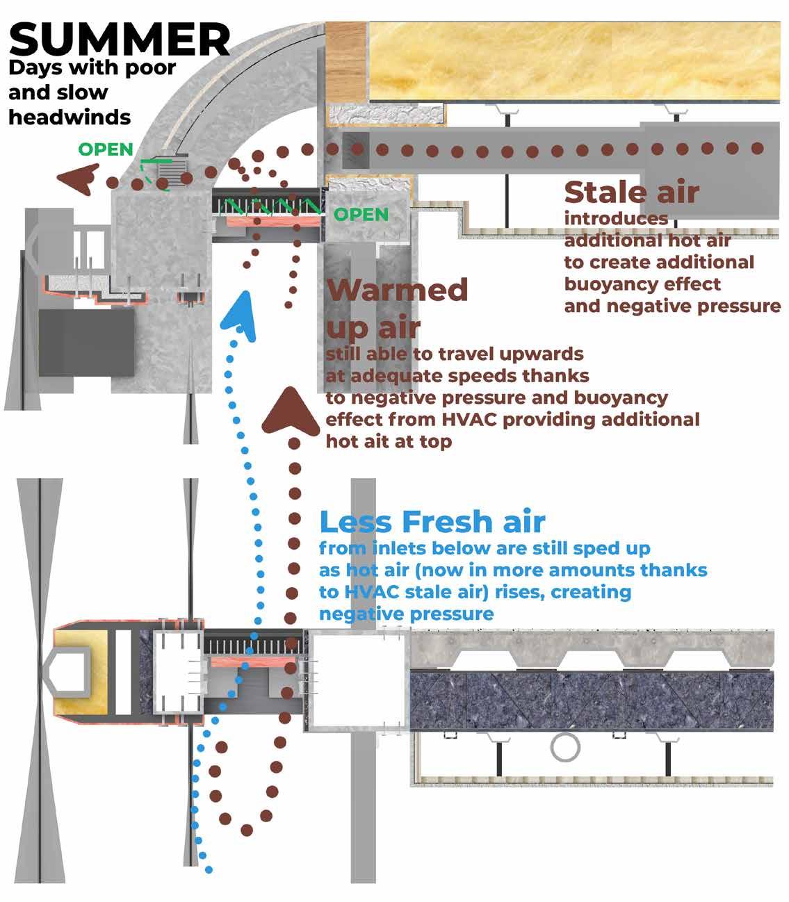
This poses the issue of extracting stale air from occupants without relying too much on a mechanical active system. That is why vent outlets at the top of the Double Skin facade help to draw out stale air from the building’s HVAC system. By using wind channels within the Double Skin facade’s cavity, any stale warm air from occupants is not only easily expelled outside, but can also be recucled within to either heat the building or help cool the building.


Additionally, the lack of any high-rise buildings nearby the site is both an advantage and disadvantage. No doubt will the double skin facade recieve plenty of passive heating and lighting for it to work, but will also have the same issue of overheating during summer months. As such, brise soleil will have to be tested to determine what works as the best compromise.
C: Intermediate composite metal decking slab

Left: Building loads
Above: Reinforcing steel members for lateral loads
ABOVE: Structural stability relies on RC slabs spanning between steel structures and ties & bracings helping with lateral stability. Using proper shear studs and cleated connections help convert any torsional stress into more-workable vertical and horizontal stress.


All elements, with the exception of RC cast in-situ, are fully dismantable with their dry connections, allowing for the most optimal chance of reuse and recycling with minimal wastage of resources.

BELOW: Fire safety within the fragment relies on fire stops in joints between the facade, walls, and floors to prevent any fire from spreading between different compartments. Ties and ‘Top Hat’ beams help to decrease any chance of internal wall or ceiling collapsing should fires ever jump room to room.


Fire stops in Curtain wall
Fire stops in Rainscreen Fire ties in slabs and columns
D: Double Skin Facade wall
Autoclaved
Constructability
Off-site prefabrication of different modules for various building systems help to decrease on-site construction times by limiting these stages to only assembly steps.


This also helps decrease net zero embodied carbon by prioritising reuse and recyclability potential of each separate module. Additionally, less construction wastage is diverted to a landfill since all modules and components are measured and produced in factories; minimal onsite wastage.

Hence, all parts can be fully dismantled into their core components, emphasising a circular economy life-cycle.
Construction vehicles were chosen for their minimal intervention and lowest possible embodied carbon. No tower cranes or massive pile drivers are required for this two-storey building. Instead, all machinery can fit on a truckbed, thus allowing multiple vehicles to enter the site at once. With telescoping mobile cranes and cement mixers working on different building masses simultaneously, this decreases construction time.
Curtain wall sourcing
The chosen option of Ultra-High Performance Concrete with natural stone veneer was a result of reducing each of the three option’s individual disadvantages by combining their advantages into one system. Using engineered concrete as a base was more beneficial than a natural masonry base, but said natural material was a more advantageous finish than the engineered concrete exterior faces.


Choosing glazing options was prioritised for the best reuse opportunities (without recycling as a ‘compromise’), thereby justifying the normalised high-embodied carbon in this market; cradle-to-cradle life cycle
Materials Tools

RIGHT: Handtools and tethers are the majority of all assembly tools. Only demountable elastic scissor lifts and telescopic mobile cranes are the most intrusive tools needed to lift larger parts in place.


This showcases minimal construction processes with high embodied carbon impacts.
Additionally, these same tools are used to dismantle building parts, and do not require heavy carbon-footprint machinery.
Any maintenance processes rely on the same tools and can be done from either the inside or outside. Such less intrusive methods mean building parts are serviced instead of replaced, thereby designing for long life and robust life cycles.
Tools and equipment for installation and maintenance
BELOW: Dry joints are prioritised between these micro connections to further enforce a cradle-to-cradle life cycle. The only exception to this would be the RC cast in-situ, which would have already offset its own carbon cost thanks to the invaluable thermal mass it provided over its lifespan.
ETFE cushions typically rely on an inflation unit to keep up the ‘Fabric first’ approach of passive heating strategies. Pairing this unit with a heat exchanger linked back to the water mains mean air supplied into these cushions are more sustainable despite requiring heating. Such heating always still contributes to strengthening the thermal barrier.
Steel to Concrete and Polymer joints Steel to Steel joints Operating ETFE cushions Green roof life cycle
Process
While the selected building components are typically seen to have a high-embodied carbon footprint, sourcing the production with recycled materials helps offset the carbon cost. Additionally, each module can be deconstructed back to its core materials and reused either in its entirety, or recycled and made into other building parts.
A: Green Roof slabLightweight Concrete Panels Lightweight concrete panels with unitised curtain wall ETFE wall system Polycarbonate wall system Glass-fibre reinforced concrete panels Terracotta Rainscreen panels
ETFE wall sourcing Double-skin facade end of life cycle
+: High load-bearing capacity +: Weather and corrosion resistance -: High-embodied carbon -: Requires wide-spread use to really benefit from economies of scale +: Plenty of reuse and recyclability options +: Strong weather resistance -: High weight requires heavy structural footprintembodied carbon -: High embodied carbon from international transportation (not available in the UK) +: High load-bearing capacity +: High tensile strength, less prone to shear deformation -: Too pale of a finish, hence poorer weathering and corrosion resistance -: Overly-hight embodied carbon to produce such a thickness
TECHNOLOGIES POSITION 01
Left: Prefabricated steel structure, green roof and double-skin facade Right: On-site assembly of rainscreen and interior elements Below: Using multiple vehicles, especially mobile cranes, for faster construction
THERMAL BRIDGING


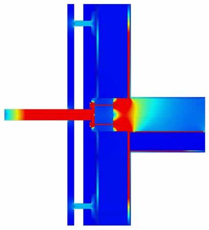


Brise Soleil connection within Double-Skin facade buildup
No thermal break may have a lighter and less intrusive construction, but fails to eliminate any cold bridges.


A thermal break halfway into the original insulation layer leads to a partial elimination of cold bridges. However, the T-Bracket plate is still close enough to the RC slab to garner some thermal transfer.
A thermal break through the entire original insulation layer better eliminates cold bridges by further spacing away the T-bracket from the RC slab.

Brise Soleil connection before Double-Skin facade buildup
Placing the thermal break well before the original insulation layer provides the same benefits of stopping cold bridges while being a much less intrusive construction technique.


This does not disrupt any prefabrication of any panels, layers or ETFE clamps.
The further the screws are from the original steel structural member and slab, the better the reduction of any cold bridges. Additionally, the thickness of the thermal break, whether it covers the cavity or not, barely has any impact on the cold bridging itself.

Brise Soleil connection within Rainscreen facade buildup
A thermal break before the insulation and within the cavity shows promising results of reducing any cold bridges while being the least intrusive to the original prefabricated module.
A thermal break on the edge of the concrete slab still has thermal bridging and is still intrusive into the original layer of insulation

A thermal break halfway into the concrete slab has better cold bridging reduction than the last interation, but is an unrealistic construction given how much it penetrates into the slab and is simply not load-bearing at all.

Reflections on Building Life & Safety

01: Vertical Fins 02: Horizontal Blades 03: Vertical and Horizontal No thermal break Thermal break before insulation Thermal break halfway into insulation Thermal break on edge of concrete slab Thermal break through entire insulation Thermal break halfway into concrete slab
BRISE SOLEIL ITERATIONS DIRECT SUN HOUR ANALYSIS
Above: Altering the position of the thermal break (TB) within the ventilation cavity Below (Left to Right): TB before insulation layer, TB filling cavity width, TB with screws further away PROTOTYPING 02
Reflections on Constructability
PASSIVE CLIMATE STRATEGY WITH DOUBLE-SKIN FACADE

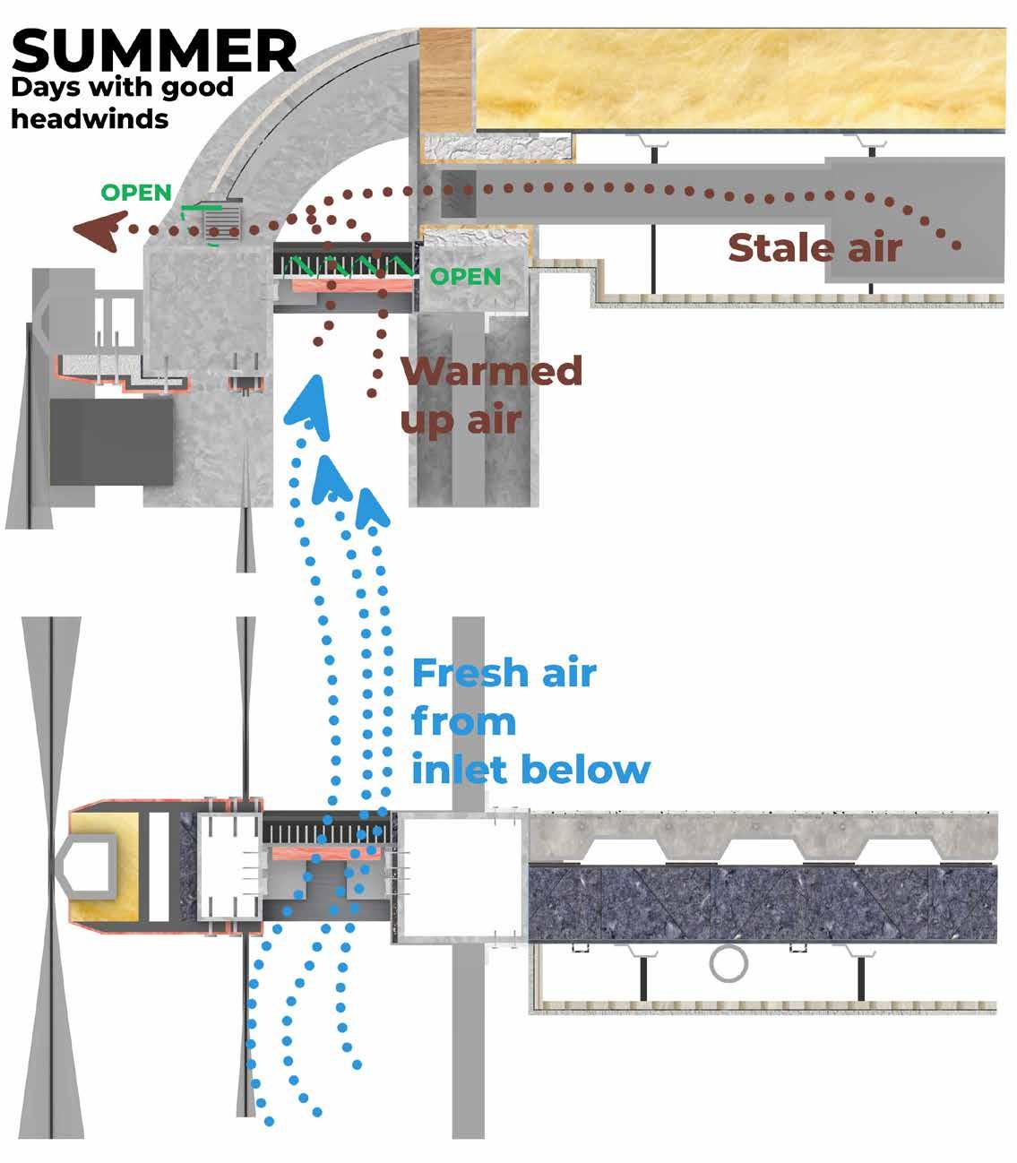


01: Summer days with ample headwinds
CONNECTION NODES
02: Summer days with poor and slow headwinds
03: Winter days with ample heating from sunlight
04: Winter days with poor and lacking heating from sunlight
Reflection on Technologies Position
With CPU[ai]’s primary focus of biophilic design, this double skin facade only provides even more climatic control of facilitating greenery within. Paired with a green roof and brise soleil, the double skin facade is made even more thermally-sound thanks to the introduction of thermal breaks, fire proofing stops and a climatic control system that utilises both passive and active systems in harmony.
RIBA Sustainable Goals Reflection
Net Zero Operational Carbon:

2. Fabric first approach is further developed through brise soleil and thermal breaks preventing cold bridging
4. Local controls can help users override automatic building heating and daylighting systems should there be any overheating or glare.
Net Embodied Carbon:
5. Materials with high embodied carbon is minimised thanks to strong reuse and recyclability potential; cradle-to-cradle design
Purpose and benefits of each bolts, shear studs, gaskets, and brackets
10. All elements are designed to be fully disassembled for a circular economy.
MAIN FRAGMENT